US4101041A - Prefillable, hermetically sealed container adapted for use with a humidifier or nebulizer head - Google Patents
Prefillable, hermetically sealed container adapted for use with a humidifier or nebulizer headDownload PDFInfo
- Publication number
- US4101041A US4101041AUS05/820,641US82064177AUS4101041AUS 4101041 AUS4101041 AUS 4101041AUS 82064177 AUS82064177 AUS 82064177AUS 4101041 AUS4101041 AUS 4101041A
- Authority
- US
- United States
- Prior art keywords
- container
- humidifier
- closed
- nebulizer
- head
- Prior art date
- Legal status (The legal status is an assumption and is not a legal conclusion. Google has not performed a legal analysis and makes no representation as to the accuracy of the status listed.)
- Expired - Lifetime
Links
- 239000006199nebulizerSubstances0.000titleclaimsabstractdescription24
- 239000007788liquidSubstances0.000claimsdescription9
- 239000012530fluidSubstances0.000claimsdescription6
- 229920001169thermoplasticPolymers0.000claimsdescription5
- 239000004416thermosoftening plasticSubstances0.000claimsdescription5
- 238000004891communicationMethods0.000claimsdescription4
- XLYOFNOQVPJJNP-UHFFFAOYSA-NwaterChemical compoundOXLYOFNOQVPJJNP-UHFFFAOYSA-N0.000description7
- 239000007789gasSubstances0.000description6
- -1polyethylenePolymers0.000description3
- 238000007789sealingMethods0.000description3
- 241000124008MammaliaSpecies0.000description2
- 239000000443aerosolSubstances0.000description2
- QVGXLLKOCUKJST-UHFFFAOYSA-Natomic oxygenChemical compound[O]QVGXLLKOCUKJST-UHFFFAOYSA-N0.000description2
- 238000011109contaminationMethods0.000description2
- 239000012153distilled waterSubstances0.000description2
- 239000003814drugSubstances0.000description2
- 229940079593drugDrugs0.000description2
- 238000002483medicationMethods0.000description2
- 239000001301oxygenSubstances0.000description2
- 229910052760oxygenInorganic materials0.000description2
- 239000004698PolyethyleneSubstances0.000description1
- 239000004743PolypropyleneSubstances0.000description1
- 238000000071blow mouldingMethods0.000description1
- 238000010276constructionMethods0.000description1
- 239000000356contaminantSubstances0.000description1
- 239000000850decongestantSubstances0.000description1
- 238000005485electric heatingMethods0.000description1
- 238000010438heat treatmentMethods0.000description1
- 239000000463materialSubstances0.000description1
- 230000013011matingEffects0.000description1
- 229940075473medical gasesDrugs0.000description1
- 238000000034methodMethods0.000description1
- 239000000203mixtureSubstances0.000description1
- 229920001748polybutylenePolymers0.000description1
- 229920000573polyethylenePolymers0.000description1
- 239000002952polymeric resinSubstances0.000description1
- 229920001155polypropylenePolymers0.000description1
- 238000002360preparation methodMethods0.000description1
- 229920005989resinPolymers0.000description1
- 239000011347resinSubstances0.000description1
- 230000000630rising effectEffects0.000description1
- 229920003002synthetic resinPolymers0.000description1
- 230000008016vaporizationEffects0.000description1
Images


Classifications
- B—PERFORMING OPERATIONS; TRANSPORTING
- B65—CONVEYING; PACKING; STORING; HANDLING THIN OR FILAMENTARY MATERIAL
- B65D—CONTAINERS FOR STORAGE OR TRANSPORT OF ARTICLES OR MATERIALS, e.g. BAGS, BARRELS, BOTTLES, BOXES, CANS, CARTONS, CRATES, DRUMS, JARS, TANKS, HOPPERS, FORWARDING CONTAINERS; ACCESSORIES, CLOSURES, OR FITTINGS THEREFOR; PACKAGING ELEMENTS; PACKAGES
- B65D1/00—Rigid or semi-rigid containers having bodies formed in one piece, e.g. by casting metallic material, by moulding plastics, by blowing vitreous material, by throwing ceramic material, by moulding pulped fibrous material or by deep-drawing operations performed on sheet material
- B65D1/02—Bottles or similar containers with necks or like restricted apertures, designed for pouring contents
Definitions
- the inventionconcerns prefillable, hermetically sealed containers and more particularly concerns fluid containers useful in association with humidifiers and nebulizers.
- the inventioncomprises a unitary, prefillable, hermetically sealed, thermoplastic container adapted for use with a humidifier or a nebulizer head, which comprises; a thermoplastic body having a closed first end and a closed removable second end, said body defining an interior chamber for holding a fluid, means for removing said second end attached to said body; a conduit providing communication between a point within said chamber adjacent said closed first end and a point within said chamber adjacent said closed second end, said conduit having frusto-conical shaped sidewalls at the point adjacent said second end; support means for said conduit, connected to said body; and means for attaching a humidifier or nebulizer head to said body upon removal of said closed, second end.
- the containers of the inventionmay be prefilled with distilled water, medications and the like and hermetically sealed.
- the removable closed endmay be quickly removed and replaced with a conventional humidifier or nebulizer head.
- the containerprovides for rapid and efficient set-up of a humidifier or nebulizer.
- FIG. 1is an isometric view of an embodiment container of the invention.
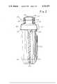
- FIG. 2is a cross-sectional side elevation of the embodiment seen in FIG. 1.
- FIG. 3is a cross-sectional front elevation of the embodiment seen in FIG. 1.
- FIG. 4is an enlarged cross-sectional in part side elevation of the removable end of the embodiment container of FIG. 1.
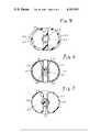
- FIG. 5is a cross-sectional view along line 5--5 of FIG. 1.
- FIG. 6is a cross-sectional view along line 6--6 of FIG. 1.
- FIG. 7is a cross-sectional view along line 7--7 of FIG. 1.
- FIG. 8is an enlarged view of the removable portion of the container seen in FIG. 1, with a means for removing.
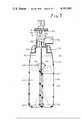
- FIG. 9is a cross-sectional side elevation of the embodiment of FIG. 1 but after replacement of the removable end with a nebulizer head.
- FIG. 10is a cross-sectional front elevation of the embodiment of FIG. 1 but after replacing the removable end with a humidifier head.
- FIG. 1an isometric view of an embodiment container 10 of the invention shows body walls 12 and a removable end 14.
- End 14includes a cap 15, a finger engaging hub 16 and a retainer strap 18 over cap 15.
- Body 12may be fabricated from any convenient material conventionally employed to fabricate thermoplastic containers.
- body 12is fabricated from a synthetic polymeric resin such as polyethylene, polypropylene, polybutylene and like resins.
- the body 12is advantageously blow-molded to provide a unitary, generally cylindrical upper portion 12A and a bifurcated lower portion comprising stems 12B and 12C.
- the two stems 12B and 12Care joined together by a common wall 20 and terminate at closed end 13.
- the upper end of wall 20terminates in an integrally molded section having the configuration of one-half of a funnel.
- This section 21together with its other half on the reverse side forms a funnel 28 (not seen in FIG. 1) on the interior wall of the container 10. The purpose of this funnel 28 configuration will be discussed in greater detail hereinafter.
- FIG. 2a cross-sectional side elevation of the container 12 as viewed in FIG. 1, it is seen that the common wall 20 separates the two stems 12B and 12C of the lower portion of container 10 to define separate wells 22 and 24 inside the container 12.
- a bore 26traverses the length of wall 20 and provides open communication between the bottom of each wall 22 and 24 through the respective apertures 40 and 42.
- the bore 26communicates at its upper end with the cavity defined by the walls of the upper portion 12A of container 12.
- the wells 22 and 24also communicate openly with the cavity defined by walls 12 of the upper portion 12A of container 10.
- the upper portion 28 of wall 20angles away from the centerline of the container 10 so that bore 26 takes on a frusto-conical shape forming an integral funnel 28 at the upper end of wall 20.
- the purpose of funnel 28is to receive a dip tube component of a nebulizer or humidifier head and direct it into sealing engagement with the bore 26 as will be described hereinafter in greater detail.
- FIG. 3is a cross-sectional front elevation of the container 10 shown in FIG. 1 and shows the stem 12C of the container 10.
- FIG. 3shows particularly that the wall 20, including funnel 28 and its upper end is an integral and continuous part of body 12.
- the rest of the container 10 structureis an integral, one piece, blow-molded unit.
- the symbol 41shows the interior cavity of container 12 above well 24.
- the removable closed end 14can also be seen to consist of cap 15 integrally molded and connected to walls 12 by neck 30.
- Neck 30has a weak, ready fracturable zone 34 just below cap 15.
- FIG. 5a cross-sectional view along line 5--5 of FIG. 1, the spacial relationship of the wall 20, wells 22 and 24 and funnel 28 are more clearly observed.
- FIG. 6a cross-sectional view along line 6--6 of FIG. 1, the base portion of the container 10 is clearly seen and shows again the relationship of the stems 12C and 12B to wall 20 and the bore 26 within wall 20.
- the apertures 40 and 42respectively, provide communication between the wells 22, 24.
- FIG. 7a cross-sectional view along line 7--7 of FIG. 1, the relationship of the stems 12C and 12B to each other wherein they are commonly joined by wall 20 is clearly shown.
- the container 10includes a hermetically sealed but removable end 14.
- Removable end 14includes a cap 15 which is an integrally molded part of wall 12, joined thereto by neck 30.
- Neck 30has helical threads 32 which are integrally molded on neck 30 of container body 12.
- a finger grasping or grasp facilitating hub 16is screw mounted on neck 30 by threads 32 engaging helical grooves 33. As shown in FIG. 4, the hub 16 has been partially removed by unscrewing.
- FIG. 8is an enlarged view of the removable portion of the container 10 after fracture and removal of hub 16 with cap 15 held against wedges 37 by retainer strap 18.
- the unique construction of the container 10permits its efficient use in association with a nebulizer or humidifier head.
- Conventional humidifier headshave a dip tube component designed to be placed in a column of water for moisturization i.e.; increasing the water vapor content of the gas prior to its administration to a mammal.
- Nebulizer heads for vaporizing a liquidare similarly constructed, with a dip tube placed in the liquid.
- the integrally molded "dip tube" and the guide means (funnel 28) associated with the container 10 of the inventionis ideally suited for rapid and efficient connection with the dip tube member of the conventional nebulizer or humidifier head.
- the container embodiment 10is employed by prefilling and hermetically sealing a liquid such as distilled water, a decongestant or like fluid medications in the wells 22 and 24 at the time the container is blow-molded.
- a liquidsuch as distilled water, a decongestant or like fluid medications
- the techniqueis well known; see for example U.S. Pat. Nos. 3,597,793 and 3,919,374.
- the prefilled container 10may be stored safely until its use is desired.
- removable end 14is removed and replaced with a conventional humidifier or nebulizer head as desired.
- the humidifier or nebulizer headmay be screwed on to the threads 32 of neck 30 of the container 10 and employed in a conventional manner well known to those skilled in the art.
- the containermay also be filled after blow-molding if so desired.
- FIG. 9there is seen a cross-sectional side elevation of the embodiment shown in FIG. 1 but after replacing severable end 14 with a conventional nebulizer head.
- the head 60has been mounted on neck 30 by taking advantage of the threads 32 and screwing head 60 thereon.
- Dip tube 62is a component part of the nebulizer 60.
- the dip tube 62is inserted into funnel 28.
- dip tube 62is pressed downward and guided by funnel 28 into hermetic sealing engagement with the bore 26 as shown in the FIG. 9.
- nebulizer head 60With the mating of tube 62 and bore 26, a continuous, uninterrupted, connection is established between the air, oxygen or other medical gas which will be introduced into head 60.
- a medical gasis conventionally directed through nebulizer head 60 (ultimately through orifice "B" of nozzle "A” which is connected to dip tube 62).
- the vacuum produceddraws liquid from wells 22 and 24 through respective apertures 40 and 42 through bore 26 and out orifice "C.” Due to the symmetry of bore 26 and the discharge apertures 40, 42 substantially equal volumes of liquid are drawn from each of the wells 22 and 24.
- the liquidfor example water, is nebulized.
- the aerosol, after entering chamber 41is usually mixed with a preparation of air as shown entering the nebulizer head through portal 70. After mixture with air, the aerosol found in chamber 41 is administered to a patient by exhaustion through portal 72.
- FIG. 10there is seen a cross-sectional front elevation of the embodiment container 10 shown in FIG. 1 but after replacing the severable end 14 with a humidifier head 65.
- the humidifier head 65is mounted in the same manner described above for nebulizer head 60.
- the dip tube 67 component of humidifier head 65mates by virtue of its guidance through funnel 28 with bore 26.
- Medical gasessuch as oxygen directed into head 65 are ultimately conveyed by dip tube 67 into the bore 26.
- the gasesare carried by bore 26 into the wells 22 and 24 holding water (well 22 not shown in FIG. 10).
- the gasultimately reaches chamber 41 after increasing its water vapor content by rising naturally through liquid filled wells 22 and 24, and is discharged through conduit 80 for administration to a mammal.
- the prefillable, hermetically sealed container of applicant's inventionis advantageously employed in association with a conventional humidifier or nebulizer head.
- the integrally molded, "dip tube" within the body of the container of applicant's inventionenables one to form a continuous path between the gas to be vaporized or moisturized and the bottom of a column of moisturant.
- the integrally molded "dip tube” of the container of the inventionenables one to rapidly mount the nebulizer or humidifier head with a minimum of exposure of the contained fluids to contamination by the atmosphere.
- the hub 16may be snap-fitted to neck 30 instead of being screw mounted.
- the container 10has been described as having a bifurcated body for forming two chambers for containing liquids, a single chamber container may be provided and the conduit 26 attached to a sidewall thereof.
- the conduit 26may also be bifurcated so that one branch reaches the point adjacent the closed end of the chamber by a different course or route than the other branch.
- a diffusermay be attached to the end of the conduit 26.
- the container 10 with its bifurcated bodyis particularly advantageous for use with humidifiers or nebulizers wherein one wishes to heat the contents of the container 10.
- the bifurcationprovides a greater container surface area for the container 10, to which a heating means such as an electric heating mantle may be applied.
Landscapes
- Engineering & Computer Science (AREA)
- Ceramic Engineering (AREA)
- Mechanical Engineering (AREA)
- Details Of Rigid Or Semi-Rigid Containers (AREA)
- Containers And Packaging Bodies Having A Special Means To Remove Contents (AREA)
Abstract
Description
Claims (6)
Priority Applications (1)
| Application Number | Priority Date | Filing Date | Title |
|---|---|---|---|
| US05/820,641US4101041A (en) | 1977-08-01 | 1977-08-01 | Prefillable, hermetically sealed container adapted for use with a humidifier or nebulizer head |
Applications Claiming Priority (1)
| Application Number | Priority Date | Filing Date | Title |
|---|---|---|---|
| US05/820,641US4101041A (en) | 1977-08-01 | 1977-08-01 | Prefillable, hermetically sealed container adapted for use with a humidifier or nebulizer head |
Publications (1)
| Publication Number | Publication Date |
|---|---|
| US4101041Atrue US4101041A (en) | 1978-07-18 |
Family
ID=25231357
Family Applications (1)
| Application Number | Title | Priority Date | Filing Date |
|---|---|---|---|
| US05/820,641Expired - LifetimeUS4101041A (en) | 1977-08-01 | 1977-08-01 | Prefillable, hermetically sealed container adapted for use with a humidifier or nebulizer head |
Country Status (1)
| Country | Link |
|---|---|
| US (1) | US4101041A (en) |
Cited By (29)
| Publication number | Priority date | Publication date | Assignee | Title |
|---|---|---|---|---|
| US4331239A (en)* | 1979-02-13 | 1982-05-25 | Societe Stendhal S.A. | Package for cosmetics and perfumes |
| US4402417A (en)* | 1981-12-28 | 1983-09-06 | Baxter Travenol Laboratories, Inc. | Bottle opening ring having shock absorbing means |
| US4620638A (en)* | 1983-10-07 | 1986-11-04 | Milupa Aktiengesellschaft | Cap for opening and extracting the contents of a vessel |
| US5242066A (en)* | 1988-11-16 | 1993-09-07 | Whitbread & Company Plc | Plastic bottles and similar containers having internal spiders |
| WO2002074374A1 (en)* | 2001-03-20 | 2002-09-26 | Aerogen, Inc. | Fluid filled ampoules and methods for their use in aerosolizers |
| US6948491B2 (en)* | 2001-03-20 | 2005-09-27 | Aerogen, Inc. | Convertible fluid feed system with comformable reservoir and methods |
| US6978941B2 (en) | 2001-05-02 | 2005-12-27 | Aerogen, Inc. | Base isolated nebulizing device and methods |
| US7040549B2 (en) | 1991-04-24 | 2006-05-09 | Aerogen, Inc. | Systems and methods for controlling fluid feed to an aerosol generator |
| US7066398B2 (en) | 1999-09-09 | 2006-06-27 | Aerogen, Inc. | Aperture plate and methods for its construction and use |
| US7174888B2 (en) | 1995-04-05 | 2007-02-13 | Aerogen, Inc. | Liquid dispensing apparatus and methods |
| US7201167B2 (en) | 2004-04-20 | 2007-04-10 | Aerogen, Inc. | Method and composition for the treatment of lung surfactant deficiency or dysfunction |
| US20070209659A1 (en)* | 1995-04-05 | 2007-09-13 | Aerogen, Inc. | Liquid dispensing apparatus and methods |
| US7290541B2 (en) | 2004-04-20 | 2007-11-06 | Aerogen, Inc. | Aerosol delivery apparatus and method for pressure-assisted breathing systems |
| US7322349B2 (en) | 2000-05-05 | 2008-01-29 | Aerogen, Inc. | Apparatus and methods for the delivery of medicaments to the respiratory system |
| US7331339B2 (en) | 2000-05-05 | 2008-02-19 | Aerogen, Inc. | Methods and systems for operating an aerosol generator |
| US7360536B2 (en) | 2002-01-07 | 2008-04-22 | Aerogen, Inc. | Devices and methods for nebulizing fluids for inhalation |
| US7600511B2 (en) | 2001-11-01 | 2009-10-13 | Novartis Pharma Ag | Apparatus and methods for delivery of medicament to a respiratory system |
| US7628339B2 (en) | 1991-04-24 | 2009-12-08 | Novartis Pharma Ag | Systems and methods for controlling fluid feed to an aerosol generator |
| US7677467B2 (en) | 2002-01-07 | 2010-03-16 | Novartis Pharma Ag | Methods and devices for aerosolizing medicament |
| US7771642B2 (en) | 2002-05-20 | 2010-08-10 | Novartis Ag | Methods of making an apparatus for providing aerosol for medical treatment |
| US7946291B2 (en) | 2004-04-20 | 2011-05-24 | Novartis Ag | Ventilation systems and methods employing aerosol generators |
| US7971588B2 (en) | 2000-05-05 | 2011-07-05 | Novartis Ag | Methods and systems for operating an aerosol generator |
| US8336545B2 (en) | 2000-05-05 | 2012-12-25 | Novartis Pharma Ag | Methods and systems for operating an aerosol generator |
| US8616195B2 (en) | 2003-07-18 | 2013-12-31 | Novartis Ag | Nebuliser for the production of aerosolized medication |
| US8742048B2 (en) | 2010-09-15 | 2014-06-03 | Henkel IP & Holding GmbH | Two-part, cyanoacrylate /cationically curable adhesive systems |
| US9108211B2 (en) | 2005-05-25 | 2015-08-18 | Nektar Therapeutics | Vibration systems and methods |
| US20160331922A1 (en)* | 2013-12-23 | 2016-11-17 | John W. Holaday | Disposable container for air hydration |
| US10124357B2 (en) | 2011-03-15 | 2018-11-13 | Silgan Dispensing Systems Corporation | Dip tube connectors and pump systems using the same |
| US11571703B2 (en) | 2010-09-16 | 2023-02-07 | The Clorox Company | Trigger dispenser |
Citations (3)
| Publication number | Priority date | Publication date | Assignee | Title |
|---|---|---|---|---|
| US781053A (en)* | 1904-04-25 | 1905-01-31 | Henry B De Vore | Paste-receptacle. |
| FR1063387A (en)* | 1952-09-17 | 1954-05-03 | Bottle | |
| US3923178A (en)* | 1974-07-25 | 1975-12-02 | American Home Prod | Container |
- 1977
- 1977-08-01USUS05/820,641patent/US4101041A/ennot_activeExpired - Lifetime
Patent Citations (3)
| Publication number | Priority date | Publication date | Assignee | Title |
|---|---|---|---|---|
| US781053A (en)* | 1904-04-25 | 1905-01-31 | Henry B De Vore | Paste-receptacle. |
| FR1063387A (en)* | 1952-09-17 | 1954-05-03 | Bottle | |
| US3923178A (en)* | 1974-07-25 | 1975-12-02 | American Home Prod | Container |
Cited By (40)
| Publication number | Priority date | Publication date | Assignee | Title |
|---|---|---|---|---|
| US4331239A (en)* | 1979-02-13 | 1982-05-25 | Societe Stendhal S.A. | Package for cosmetics and perfumes |
| US4402417A (en)* | 1981-12-28 | 1983-09-06 | Baxter Travenol Laboratories, Inc. | Bottle opening ring having shock absorbing means |
| US4620638A (en)* | 1983-10-07 | 1986-11-04 | Milupa Aktiengesellschaft | Cap for opening and extracting the contents of a vessel |
| US5242066A (en)* | 1988-11-16 | 1993-09-07 | Whitbread & Company Plc | Plastic bottles and similar containers having internal spiders |
| US7628339B2 (en) | 1991-04-24 | 2009-12-08 | Novartis Pharma Ag | Systems and methods for controlling fluid feed to an aerosol generator |
| US7040549B2 (en) | 1991-04-24 | 2006-05-09 | Aerogen, Inc. | Systems and methods for controlling fluid feed to an aerosol generator |
| US8561604B2 (en) | 1995-04-05 | 2013-10-22 | Novartis Ag | Liquid dispensing apparatus and methods |
| US20070209659A1 (en)* | 1995-04-05 | 2007-09-13 | Aerogen, Inc. | Liquid dispensing apparatus and methods |
| US7174888B2 (en) | 1995-04-05 | 2007-02-13 | Aerogen, Inc. | Liquid dispensing apparatus and methods |
| US20070023547A1 (en)* | 1999-09-09 | 2007-02-01 | Aerogen, Inc. | Aperture plate and methods for its construction and use |
| US8398001B2 (en) | 1999-09-09 | 2013-03-19 | Novartis Ag | Aperture plate and methods for its construction and use |
| US7066398B2 (en) | 1999-09-09 | 2006-06-27 | Aerogen, Inc. | Aperture plate and methods for its construction and use |
| US8336545B2 (en) | 2000-05-05 | 2012-12-25 | Novartis Pharma Ag | Methods and systems for operating an aerosol generator |
| US7748377B2 (en) | 2000-05-05 | 2010-07-06 | Novartis Ag | Methods and systems for operating an aerosol generator |
| US7971588B2 (en) | 2000-05-05 | 2011-07-05 | Novartis Ag | Methods and systems for operating an aerosol generator |
| US7331339B2 (en) | 2000-05-05 | 2008-02-19 | Aerogen, Inc. | Methods and systems for operating an aerosol generator |
| US7322349B2 (en) | 2000-05-05 | 2008-01-29 | Aerogen, Inc. | Apparatus and methods for the delivery of medicaments to the respiratory system |
| US7195011B2 (en) | 2001-03-20 | 2007-03-27 | Aerogen, Inc. | Convertible fluid feed system with comformable reservoir and methods |
| WO2002074374A1 (en)* | 2001-03-20 | 2002-09-26 | Aerogen, Inc. | Fluid filled ampoules and methods for their use in aerosolizers |
| US7100600B2 (en)* | 2001-03-20 | 2006-09-05 | Aerogen, Inc. | Fluid filled ampoules and methods for their use in aerosolizers |
| US6948491B2 (en)* | 2001-03-20 | 2005-09-27 | Aerogen, Inc. | Convertible fluid feed system with comformable reservoir and methods |
| US7032590B2 (en) | 2001-03-20 | 2006-04-25 | Aerogen, Inc. | Fluid filled ampoules and methods for their use in aerosolizers |
| US8196573B2 (en) | 2001-03-20 | 2012-06-12 | Novartis Ag | Methods and systems for operating an aerosol generator |
| US6978941B2 (en) | 2001-05-02 | 2005-12-27 | Aerogen, Inc. | Base isolated nebulizing device and methods |
| US7104463B2 (en) | 2001-05-02 | 2006-09-12 | Aerogen, Inc. | Base isolated nebulizing device and methods |
| US7600511B2 (en) | 2001-11-01 | 2009-10-13 | Novartis Pharma Ag | Apparatus and methods for delivery of medicament to a respiratory system |
| US8539944B2 (en) | 2002-01-07 | 2013-09-24 | Novartis Ag | Devices and methods for nebulizing fluids for inhalation |
| US7677467B2 (en) | 2002-01-07 | 2010-03-16 | Novartis Pharma Ag | Methods and devices for aerosolizing medicament |
| US7360536B2 (en) | 2002-01-07 | 2008-04-22 | Aerogen, Inc. | Devices and methods for nebulizing fluids for inhalation |
| US7771642B2 (en) | 2002-05-20 | 2010-08-10 | Novartis Ag | Methods of making an apparatus for providing aerosol for medical treatment |
| US8616195B2 (en) | 2003-07-18 | 2013-12-31 | Novartis Ag | Nebuliser for the production of aerosolized medication |
| US7290541B2 (en) | 2004-04-20 | 2007-11-06 | Aerogen, Inc. | Aerosol delivery apparatus and method for pressure-assisted breathing systems |
| US7267121B2 (en) | 2004-04-20 | 2007-09-11 | Aerogen, Inc. | Aerosol delivery apparatus and method for pressure-assisted breathing systems |
| US7946291B2 (en) | 2004-04-20 | 2011-05-24 | Novartis Ag | Ventilation systems and methods employing aerosol generators |
| US7201167B2 (en) | 2004-04-20 | 2007-04-10 | Aerogen, Inc. | Method and composition for the treatment of lung surfactant deficiency or dysfunction |
| US9108211B2 (en) | 2005-05-25 | 2015-08-18 | Nektar Therapeutics | Vibration systems and methods |
| US8742048B2 (en) | 2010-09-15 | 2014-06-03 | Henkel IP & Holding GmbH | Two-part, cyanoacrylate /cationically curable adhesive systems |
| US11571703B2 (en) | 2010-09-16 | 2023-02-07 | The Clorox Company | Trigger dispenser |
| US10124357B2 (en) | 2011-03-15 | 2018-11-13 | Silgan Dispensing Systems Corporation | Dip tube connectors and pump systems using the same |
| US20160331922A1 (en)* | 2013-12-23 | 2016-11-17 | John W. Holaday | Disposable container for air hydration |
Similar Documents
| Publication | Publication Date | Title |
|---|---|---|
| US4101041A (en) | Prefillable, hermetically sealed container adapted for use with a humidifier or nebulizer head | |
| US3001524A (en) | Aerosol dispensing apparatus | |
| USRE37734E1 (en) | Dispensing bulb | |
| ES2222430T3 (en) | DISPENSER WITH DRILLING NEEDLE FOR MATERIALS TO MIX DURING DISTRIBUTION. | |
| US3012555A (en) | Dispensing package for material under pressure | |
| US3361306A (en) | Aerosol unit dispensing uniform amounts of a medically active ingredient | |
| US4154369A (en) | Non-refillable dispensing container | |
| KR0142416B1 (en) | Aerosol dispenser | |
| JPH037162A (en) | Ampoule | |
| EP0195778A4 (en) | Liquid container dispensing cap structure. | |
| JP2001524384A (en) | Dispenser with manually operable ejection device | |
| EP0327397A3 (en) | Ampoules | |
| KR890701159A (en) | Powdered Pharmaceutical Reagent Containers | |
| US3104062A (en) | Nebulizing dispenser | |
| ZA817475B (en) | Containers and holders thereof for use in electrostatic spraying | |
| KR0109269Y1 (en) | Single use spray dispensing assembly | |
| EP0443192A3 (en) | Discharge head for fluids | |
| KR870008626A (en) | Spray cap assembly | |
| US4083496A (en) | Atomizer | |
| KR860008405A (en) | Containers for liquid gases | |
| IT202000009088A1 (en) | DEVICE AND KIT FOR DELIVERY OF A NEBULIZED SUBSTANCE | |
| US4471886A (en) | Device for spraying medicinal liquid | |
| US2686696A (en) | Atomizer | |
| US642211A (en) | Atomizer. | |
| GB2328876A (en) | Eye medication spray dispenser |
Legal Events
| Date | Code | Title | Description |
|---|---|---|---|
| AS | Assignment | Owner name:DART INDUSTRIES, INC., 2211 SANDERS ROAD, NORTHBRO Free format text:ASSIGNMENT OF ASSIGNORS INTEREST.;ASSIGNOR:BECTON, DICKINSON AND COMPANY;REEL/FRAME:004257/0066 Effective date:19840229 | |
| AS | Assignment | Owner name:PROFESSIONAL MEDICAL PRODUCTS, INC., 525 NORTH EME Free format text:ASSIGNMENT OF ASSIGNORS INTEREST.;ASSIGNOR:DART INDUSTRIES INC., A DE CORP;REEL/FRAME:004659/0818 Effective date:19861027 Owner name:PROFESSIONAL MEDICAL PRODUCTS, INC., A DE CORP,SOU Free format text:ASSIGNMENT OF ASSIGNORS INTEREST;ASSIGNOR:DART INDUSTRIES INC., A DE CORP;REEL/FRAME:004659/0818 Effective date:19861027 | |
| AS | Assignment | Owner name:GENERAL ELECTRIC CREDIT CORPORATION, A CORP. OF N. Free format text:ASSIGNMENT OF ASSIGNORS INTEREST.;ASSIGNOR:PROFESSIONAL MEDICAL PRODUCTS, INC.;REEL/FRAME:004665/0944 Effective date:19860915 | |
| AS | Assignment | Owner name:PROFESSIONAL MEDICAL PRODUCTS, INC., SOUTH CAROLIN Free format text:RELEASED BY SECURED PARTY;ASSIGNOR:GENERAL ELECTRIC CAPITAL CORPORATION, F/K/A GENERAL ELECTRIC CREDIT CORPORATION;REEL/FRAME:005300/0821 Effective date:19900328 | |
| AS | Assignment | Owner name:TYCO INTERNATIONAL (US) INC., NEW HAMPSHIRE Free format text:CHANGE OF NAME;ASSIGNOR:TYCO INTERNATIONAL LTD.;REEL/FRAME:008604/0376 Effective date:19970702 Owner name:KENDALL COMPANY, THE, MASSACHUSETTS Free format text:MERGER;ASSIGNOR:PROFESSIONAL MEDICAL PRODUCTS, INC.;REEL/FRAME:008604/0366 Effective date:19960531 Owner name:TYCO INTERNATIONAL LTD., NEW HAMPSHIRE Free format text:MERGER;ASSIGNOR:KENDALL COMPANY, THE;REEL/FRAME:008604/0384 Effective date:19961231 |