US4100398A - Laminated electrically heatable window with electrical connectors - Google Patents
Laminated electrically heatable window with electrical connectorsDownload PDFInfo
- Publication number
- US4100398A US4100398AUS05/790,042US79004277AUS4100398AUS 4100398 AUS4100398 AUS 4100398AUS 79004277 AUS79004277 AUS 79004277AUS 4100398 AUS4100398 AUS 4100398A
- Authority
- US
- United States
- Prior art keywords
- electrically conductive
- electrically
- conductive lead
- electrical
- combination according
- Prior art date
- Legal status (The legal status is an assumption and is not a legal conclusion. Google has not performed a legal analysis and makes no representation as to the accuracy of the status listed.)
- Expired - Lifetime
Links
Images

Classifications
- B—PERFORMING OPERATIONS; TRANSPORTING
- B32—LAYERED PRODUCTS
- B32B—LAYERED PRODUCTS, i.e. PRODUCTS BUILT-UP OF STRATA OF FLAT OR NON-FLAT, e.g. CELLULAR OR HONEYCOMB, FORM
- B32B17/00—Layered products essentially comprising sheet glass, or glass, slag, or like fibres
- B32B17/06—Layered products essentially comprising sheet glass, or glass, slag, or like fibres comprising glass as the main or only constituent of a layer, next to another layer of a specific material
- B32B17/10—Layered products essentially comprising sheet glass, or glass, slag, or like fibres comprising glass as the main or only constituent of a layer, next to another layer of a specific material of synthetic resin
- B32B17/10005—Layered products essentially comprising sheet glass, or glass, slag, or like fibres comprising glass as the main or only constituent of a layer, next to another layer of a specific material of synthetic resin laminated safety glass or glazing
- B32B17/10165—Functional features of the laminated safety glass or glazing
- B32B17/10293—Edge features, e.g. inserts or holes
- B32B17/10302—Edge sealing
- B—PERFORMING OPERATIONS; TRANSPORTING
- B32—LAYERED PRODUCTS
- B32B—LAYERED PRODUCTS, i.e. PRODUCTS BUILT-UP OF STRATA OF FLAT OR NON-FLAT, e.g. CELLULAR OR HONEYCOMB, FORM
- B32B17/00—Layered products essentially comprising sheet glass, or glass, slag, or like fibres
- B32B17/06—Layered products essentially comprising sheet glass, or glass, slag, or like fibres comprising glass as the main or only constituent of a layer, next to another layer of a specific material
- B32B17/10—Layered products essentially comprising sheet glass, or glass, slag, or like fibres comprising glass as the main or only constituent of a layer, next to another layer of a specific material of synthetic resin
- B32B17/10005—Layered products essentially comprising sheet glass, or glass, slag, or like fibres comprising glass as the main or only constituent of a layer, next to another layer of a specific material of synthetic resin laminated safety glass or glazing
- B32B17/10009—Layered products essentially comprising sheet glass, or glass, slag, or like fibres comprising glass as the main or only constituent of a layer, next to another layer of a specific material of synthetic resin laminated safety glass or glazing characterized by the number, the constitution or treatment of glass sheets
- B32B17/10036—Layered products essentially comprising sheet glass, or glass, slag, or like fibres comprising glass as the main or only constituent of a layer, next to another layer of a specific material of synthetic resin laminated safety glass or glazing characterized by the number, the constitution or treatment of glass sheets comprising two outer glass sheets
- B—PERFORMING OPERATIONS; TRANSPORTING
- B32—LAYERED PRODUCTS
- B32B—LAYERED PRODUCTS, i.e. PRODUCTS BUILT-UP OF STRATA OF FLAT OR NON-FLAT, e.g. CELLULAR OR HONEYCOMB, FORM
- B32B17/00—Layered products essentially comprising sheet glass, or glass, slag, or like fibres
- B32B17/06—Layered products essentially comprising sheet glass, or glass, slag, or like fibres comprising glass as the main or only constituent of a layer, next to another layer of a specific material
- B32B17/10—Layered products essentially comprising sheet glass, or glass, slag, or like fibres comprising glass as the main or only constituent of a layer, next to another layer of a specific material of synthetic resin
- B32B17/10005—Layered products essentially comprising sheet glass, or glass, slag, or like fibres comprising glass as the main or only constituent of a layer, next to another layer of a specific material of synthetic resin laminated safety glass or glazing
- B32B17/10165—Functional features of the laminated safety glass or glazing
- B32B17/10174—Coatings of a metallic or dielectric material on a constituent layer of glass or polymer
- B32B17/10183—Coatings of a metallic or dielectric material on a constituent layer of glass or polymer being not continuous, e.g. in edge regions
- B—PERFORMING OPERATIONS; TRANSPORTING
- B32—LAYERED PRODUCTS
- B32B—LAYERED PRODUCTS, i.e. PRODUCTS BUILT-UP OF STRATA OF FLAT OR NON-FLAT, e.g. CELLULAR OR HONEYCOMB, FORM
- B32B17/00—Layered products essentially comprising sheet glass, or glass, slag, or like fibres
- B32B17/06—Layered products essentially comprising sheet glass, or glass, slag, or like fibres comprising glass as the main or only constituent of a layer, next to another layer of a specific material
- B32B17/10—Layered products essentially comprising sheet glass, or glass, slag, or like fibres comprising glass as the main or only constituent of a layer, next to another layer of a specific material of synthetic resin
- B32B17/10005—Layered products essentially comprising sheet glass, or glass, slag, or like fibres comprising glass as the main or only constituent of a layer, next to another layer of a specific material of synthetic resin laminated safety glass or glazing
- B32B17/1055—Layered products essentially comprising sheet glass, or glass, slag, or like fibres comprising glass as the main or only constituent of a layer, next to another layer of a specific material of synthetic resin laminated safety glass or glazing characterized by the resin layer, i.e. interlayer
- B32B17/10761—Layered products essentially comprising sheet glass, or glass, slag, or like fibres comprising glass as the main or only constituent of a layer, next to another layer of a specific material of synthetic resin laminated safety glass or glazing characterized by the resin layer, i.e. interlayer containing vinyl acetal
- B—PERFORMING OPERATIONS; TRANSPORTING
- B32—LAYERED PRODUCTS
- B32B—LAYERED PRODUCTS, i.e. PRODUCTS BUILT-UP OF STRATA OF FLAT OR NON-FLAT, e.g. CELLULAR OR HONEYCOMB, FORM
- B32B2367/00—Polyesters, e.g. PET, i.e. polyethylene terephthalate
- H—ELECTRICITY
- H05—ELECTRIC TECHNIQUES NOT OTHERWISE PROVIDED FOR
- H05B—ELECTRIC HEATING; ELECTRIC LIGHT SOURCES NOT OTHERWISE PROVIDED FOR; CIRCUIT ARRANGEMENTS FOR ELECTRIC LIGHT SOURCES, IN GENERAL
- H05B3/00—Ohmic-resistance heating
- H05B3/84—Heating arrangements specially adapted for transparent or reflecting areas, e.g. for demisting or de-icing windows, mirrors or vehicle windshields
- H05B3/86—Heating arrangements specially adapted for transparent or reflecting areas, e.g. for demisting or de-icing windows, mirrors or vehicle windshields the heating conductors being embedded in the transparent or reflecting material
- H—ELECTRICITY
- H05—ELECTRIC TECHNIQUES NOT OTHERWISE PROVIDED FOR
- H05B—ELECTRIC HEATING; ELECTRIC LIGHT SOURCES NOT OTHERWISE PROVIDED FOR; CIRCUIT ARRANGEMENTS FOR ELECTRIC LIGHT SOURCES, IN GENERAL
- H05B2203/00—Aspects relating to Ohmic resistive heating covered by group H05B3/00
- H05B2203/013—Heaters using resistive films or coatings
- H—ELECTRICITY
- H05—ELECTRIC TECHNIQUES NOT OTHERWISE PROVIDED FOR
- H05B—ELECTRIC HEATING; ELECTRIC LIGHT SOURCES NOT OTHERWISE PROVIDED FOR; CIRCUIT ARRANGEMENTS FOR ELECTRIC LIGHT SOURCES, IN GENERAL
- H05B2203/00—Aspects relating to Ohmic resistive heating covered by group H05B3/00
- H05B2203/016—Heaters using particular connecting means
Definitions
- This inventionrelates to laminated electrically heatable windows, and more particularly to an improved bus bar termination for making electrical contact between an electrically conductive layer in the window and a supply of electric current.
- One type of electrically heatable windowincludes a very thin conductive metal film on a carrier film of transparent plastic embedded in the window and extending over most of the area of the window.
- the metal filmis so thin it is transparent to light, and when an electrical current is passing between its opposite edges, the metal acts as a sheet resistor.
- the metal filmcarries enough current to heat the windshield to inhibit condensation of fog or frost and remove accumulations of ice or snow.
- the thin film of conductive metalis vacuum-deposited on a thin carrier film of plastic such as polyethylene terephthalate, commercially available as Du Pont's "Mylar".
- the carrier filmis sandwiched between a pair of transparent sheets of interlayer material typically polyvinyl butyral which are, in turn, sandwiched between exterior face sheets of glass.
- Electrically conductive bus barstypically made of thin copper foil, are laminated into the heatable window between the vacuum coated side of the carrier film and the adjacent interlayer so they are in electrical contact with the thin conductive film.
- Electric current applied between the conductive bus bars along opposite edges of conductive areas within the windowassures uniform heating over the area of the window.
- the ends of the conductive bus barsare typically extended beyond the edge of the window for making electrical connection to a harness cable leading to the automobile alternator for supplying electric current to the window.
- the ends of the foil bus bars extending beyond the edge of the windoware substantially completely embedded in a flat, projecting laminated tab comprising relatively thin face sheets of plastic. The tab has small exposed areas above each bus bar for providing electrical contact between the bus bars and the harness cable.
- Such electrically heatable windows for automobilesare normally manufactured by initially forming a "prelaminate" which includes the conductive carrier film, the plastic interlayers heat-bonded to opposite sides of the carrier film, and the bus bars embedded between the interlayers and the conductive film.
- the prelaminatesthen undergo a laminating process in which face sheets of glass are applied to the opposite sides of the prelaminate.
- the glasstypically is applied by evacuating excess air out of the laminate and applying heat and pressure, such as by infrared heating or in an autoclave or by use of nip rolls, to tackify the interlayers to aid in bonding them to the glass.
- the end-product from the laminating processcomprises the laminated electrically heatable window having terminal connections for the embedded bus bars extending from a corner of the window in the projecting plactic tab described above.
- the windowis then shipped to the automobile assembly plant where the window is installed in the automobile.
- the terminal contacts of the bus barsare then connected to a harness cable for supplying electric current to the window heating element from the automobile alternator or generator.
- the contact on the end of the harness cableis a relatively complicated fitting which includes spring metal electrical contacts encased in an electrically insulated housing having a hinged closure.
- the bus bar tab at the corner of the windowis fitted into the housing so the exposed areas of the contacts overlie the bus bars.
- the closureis then snapped to a closed position over the tab to apply pressure for holding the bus bars against the electrical contacts in the fitting.
- the harness terminalsmay be applied at the windshield laminating plant and shipped pre-assembled to the assembly plant.
- connection between the harness cable and the bus barleads be in a waterproof seal, because this terminal connection, when installed in the automobile, is normally on the weather-side of the automobile firewall.
- the harness cable fitting described aboverelies on a sealing gasket and may be only partially waterproof.
- bus bar terminationIt is also desirable for the bus bar termination to satisfy such requirements as (1) low cost, (2) good electrical contact after being subjected to the laminating process, (3) simplicity of attachment to the electrical cable harness, (4) minimal autoclave oil penetration which would disrupt the electrical contact, (5) adequate "pull" strength to resist tearing or separation of the bus bars, and (6) permitting the connector joint to be extended a substantial distance from the windshield, if desired.
- the harness cable fitting described abovehas adequate pull strength, but only partially satisfies these other requirements.
- the present inventionprovides an improved bus bar termination which is completely waterproof and also meets all the requirements enumerated above.
- a preferred embodiment of the present inventionincludes a bus bar termination for a laminated electrically heatable window in which the window includes an electric resistive element embedded in the window, and an electrically conductive bus bar lead extending from an edge of the window.
- the bus bar leadis electrically connected to a cable for conducting electrical current to the resistive element of the window.
- the cablecan be the harness cable leading from the alternator or generator.
- Each bus bar terminationincludes separate electrical contacts on the ends of the bus bar lead and the harness cable for forming a cooperating pin and socket connection.
- An electrically insulating protective sleeveis sealed around the cooperating pin and socket connection to make a hermetically sealed, completely waterproof enclosure for the electrical contact.
- the bus bar termination of this inventionpermits quick, low labor content assembly of the cable and bus bar contacts.
- the cooperating pin and socketcan be easily fitted together in a pressure fit which makes a reliable connection.
- the protective sleeveis an initially loose-fitting section of a heat shrinkable tubing. After the pin and socket are connected, the heat shrinkable tubing is slipped over the connection and heat treated so it shrinks to a tight hermetic seal around the connection.
- the steps of connecting the contacts and heat-shrinking the protective sleevecan be performed after final lamination by the glass laminator, so that finished windows can be stored and then shipped to the automobile assembly plants with the harness cables attached. Windows using this bus bar termination can be completely inspected for electrical integrity before sealing the contact, so that rejects from the glass laminating processing do not include the cost of electrical terminal parts and the labor for connecting them. Prelaminates are also similarly readily inspected.
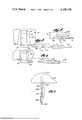
- FIG. 1is a schematic view showing a typical laminated electrically heatable windshield constructed in accordance with principles of this invention
- FIG. 2is a fragmentary schematic cross-section elevation view taken on line 2--2 of FIG. 1 and showing a detail of the bus bar termination of this invention, this view being greatly exaggerated and having some elements proportionately different in size from their actual size for the purpose of clarity;
- FIG. 3is a fragmentary, partly exploded, plan view enlarged to show the portion of the bus bar termination within the circle 3 of FIG. 1;
- FIG. 4is a fragmentary, partly exploded plan view, partly broken away, illustrating an alternate embodiment of electrical termination
- FIG. 5is a fragmentary plan view illustrating the completed bus bar termination after the components of FIG. 3 are assembled and sealed.
- FIG. 6is a fragmentary, partly exploded plan view, illustrating a further alternate embodiment of the electrical termination.
- FIG. 1illustrates a typical electrically heatable automobile windshield 10 constructed according to the principles of this invention.
- the windshieldis transparent throughout most of its area and includes an electrically conductive or resistive layer of vacuum-deposited metal embedded in it for electrically heating the window to remove ice or frost, for example.
- the conductive layer of metalis sufficiently thin to be transparent.
- the inventionalso is useful with other types of conductive layers in the windshield, such as metal oxide, fine conductive wire, or frit type resistive elements.
- the bus bar 12is embedded in the window at a location just slightly inboard the top edge of the window, and the bus bar extends substantially the entire width of the window.
- a lead portion 14 of the bus bar 12extends down along one edge of the window.
- the lead portion 14 of the bus bar 12includes a terminal portion 16 which extends beyond the bottom edge of the window and is shown in greater detail in FIGS. 2 and 3.
- the extension beyond the glass edgeis exaggerated for clarity in these figures.
- the bus bar terminationis almost adjacent the glass edge.
- the bus bar and its exterior terminal portioncan be a continuous conductive strip, or the terminal portion of the bus bar can be a separate conductive tab, such as that described in greater detail below.
- a second bus bar 18extends along the bottom edge of the window and terminates in an electrical terminal identical in construction to terminal 16, which also extends beyond the bottom edge of the window.
- the bus bar 18makes a slight downward jog at the mid-line of the window to form a lower extension 19 extending half-way across the window.
- a third bus bar 20extending approximately half-way across the window is embedded along the lower edge of the window immediately above the lower extension 19 of the bus bar 18.
- the third bus bar 20also has an electrical terminal lead extending beyond the bottom edge of the window which is identical in construction to the terminal leads for the other two bus bars.
- the bus barsmake electrical contact to the conductive layer. There is no electrical continuity between the parallel sections of bus bars 19 and 20.
- An electrical isolation line 22extends vertically across the window and divides the embedded conductive film into two conductive areas 24 and 26.
- the electrical isolation lineis an extremely fine scribe line which interrupts the electrically conductive film in the window, and typically this line is almost invisible. Additional isolation lines (not shown) may be provided between adjacent bus bars and along the leads to the bus bars for limiting current flow between the bus bars.
- the current through the two conductive areas 24 and 26is applied in two phases from a three phase alternator 28 which distributes electric current in a circuit which includes a power supply 30, such as the automobile storage battery.
- the third phaseis typically applied to the back window of the automobile.
- Other power sourcesmay be D.C. or single phase A.C. and require corresponding changes in the bus bar configuration, with the elimination of the isolation line 22. If a three phase power source is used for the windshield only, then two such isolation lines would be present and would divide the windshield into three approximately equal areas with appropriate reconfiguration of the bus bars.
- FIG. 2illustrates the detailed construction of the electrical termination 16 for transmitting electric current to the resistive areas of the windshield.
- the windshield 10has two exterior face plies 32 of glass.
- a pair of transparent plastic interlayers 34 and 35preferably made of polyvinyl butyral, are bonded to and between the sheets of glass.
- a carrier film 36 of transparent plasticsuch as polyethylene terephthalate is sandwiched between the interlayers 34 and 35 over most of the area of the window and is bonded to both interlayers.
- the carrier film 36has an extremely thin layer 38 of a conductive metal on at least one of its surfaces (shown greatly exaggerated in thickness in FIG. 2).
- the conductive metal layer 38is applied to the carrier film 36 preferably by vacuum deposition techniques.
- the interlayers 34 and 35typically are bonded to the metal coated surface of the carrier film, or to the carrier film itself, by conventional heat and pressure lamination in a manner well known in the art and referred to in U.S. Pat. No. 3,718,535.
- a prelaminatecomprising the interlayers 34 and 35 and the sandwiched carrier film 36 and conductive layer 38 are made by subjecting the prelaminate to pressures of from 150 to 200 psi at elevated temperatures, say 200° F., for approximately 2 hours.
- the prelaminatealso includes the bus bars 12, 14, 18, 19 and 20 sandwiched between the carrier film 36 and the prelaminate 34 overlying the carrier film so that one side of each bus bar is in direct electrical contact with the conductive metal layer 38, and the other side of each bus bar is bonded to the adjacent interlayer 34.
- FIGS. 2 and 3illustrate one embodiment of a bus bar termination according to this invention.
- the end portions of the bus bar extensions 14, 19 and 20extend to a lower corner of the windshield 10, as shown in FIG. 1, and then extend beyond the bottom edge of the windshield to provide terminal connections for electrically connecting the bus bars to an electric harness cable 40 which conducts electric current to the resistive elements of the windshield.
- the harness cable 40can be a conventional insulated conductor wire extending from the terminal connection of the bus bars to a junction box (not shown) in the automobile. Connections to the junction box then lead to the three-phase power source.
- the terminal end of the harness cable 40includes a tubular receptacle clip 44 or socket (preferably about 1/16 inch I.D. by 1/2 inch long) electrically connected to the end of the harness cable. As shown in FIG. 3, the longitudinal axis of the tubular receptacle 44 is collinear with the longitudinal axis of the cable 40.
- the terminal connection 16also includes a male electrical contact which comprises an elongated cylindrical-shaped solid metal shank 46 having a male end pin 48 of smaller diameter which is sized for a snug reliable pressure fit into the receptacle tube 44.
- the solid cylindrical shank portion 46 of the male end pinhas an outside diameter which matches the outside diameter of the receptacle 44.
- the shank 46 of the male end pinis attached to, or continuous with, a conductive metal tab 50 which is attached to the terminal portion of the bus bar 14 at its opposite end.
- a major portion of the conductive tab 50is embedded in an edge portion of the window.
- the remaining portion of the conductive tab 50extends outside the edge of the window for for connection to the male terminal contact pin.
- the embedded portion of the tab 50includes a bare metal section 52 in electrical contact with the end of the bus bar 14, the two being attached by spot welding or soldering (not shown).
- the remaining embedded portion of the tab 50 and the portion of the tab which extends outside the edge of the windoware coated with a layer 54 of suitable electrical insulator such as a baked-on ceramic or lacquer.
- the coated portion of the tab which is located immediately inboard the edge of the windowis bonded to the top and bottom interlayers 34 and 35 to insure a waterproof vinyl seal against the tab 50.
- the area of the carrier film 36 coincident with the tabis precut away to form a void for receiving the tab to avoid a thickness build up between the sheets of glass.
- the outer surface of the cylindrical shank 46also includes an outer coating of the electrically insulating material 54.
- the conductive tab 50is preferably a thin metal strip (the dimension typically being 0.005 inch in thickness by 1/4 inch in width by 1 inch in length).
- the axis of the male electrical contactis preferably perpendicular to the long dimension of the tab 50 to minimize the projected length beyond the glass edge in order to facilitate final lamination of the windshield. This also enables easy manufacture by wrapping the flat tab around the shank 46 and soldering if the pin, shank and flat strip are not formed integrally.
- the connector on the end of the tabis located immediately adjacent the edge of the window, preferably being spaced from the window by a distance less that the diameter of the tab. This construction minimizes damage to the tab during the customary tacking by nip rollers prior to autoclave lamination.
- the male contactpreferably is located so that a substantial portion of the length of the shank 46 extends beyond the edge of the tab 50 (typically the shank extends approximately 1/4 inch away from the edge of the tab 50).
- the shank of the connectorincludes electrical insulation and the pin is bare.
- the tab 50is made from a material, such as phosphor bronze, or brass, having a greater strength and shear modulus than the bus bar. This construction provides good resistance to shear of the tab at the edge of the window when the terminal connection is subjected to pull in a direction which would tend to tear the exterior portion of the tab adjacent the edge of the window or prelaminate.
- FIG. 4shows an alternate form of the invention in which the male and female parts of the terminal connection shown in FIG. 3 are interchanged to form a connection in which a tubular electrical receptacle 144 is integral with the projecting end portion of the tab 50, and a male end pin 148 extends outwardly from the end of a harness cable 140 for supplying electric current to the resistive element of the window.
- the tubular socket 144projects away from the edge of the tab 50 in a manner similar to the male connector shown in FIG. 3, and the male end pin 148 makes the same snug, reliable pressure fit in the socket 144.
- the terminal contacts for the bus bar 20 and the bus bar extension 19are constructed in a manner identical to that shown in FIGS. 3 and 4.
- the prelaminate which includes the embedded bus barsalso includes the projecting portions of the tabs 50 and the electrical contacts attached to the ends of the tabs, whether they be the male contact shown in FIG. 3, or the female contact shown in FIG. 4.
- these prelaminatesare typically laminated with the face plies 32 of glass in a process which includes applying heat by an oil medium in an autoclave to bond the glass face plies to the plastic interlayers.
- the laminatorthen can assemble the bus bar terminal connections in the manner shown in FIGS. 3 or 4.
- the present inventionallows these terminal connections to be assembled by inserting the male electrical pin into the female electrical socket to form a snug pressure fit.
- the contactscan be soldered after insertion if desired.
- a loose-fitting protective sleeve 56comprising a section of conventional heat shrinkable tubing which is slipped over the mating electric joint so that both the end of the electrical harness cable 40 and the projecting portion of the insulated shank 46 are covered by the tubing.
- the tubingis then heat treated so it shrinks to a tight hermetic seal around the opposite ends of the electrical connection. Since the diameters of the shank 46 and socket 44 are the same, a smooth connection is present on the inside of the heat shrink tubing. This assures secure electric insulation and a seal against weather. Further, the heat shrink tubing grips the connection to help prevent accidental dislodging making the harness cable essentially a permanent part of the window.
- the completed sealed connectionis illustrated in FIG. 5.
- the terminal connection shown in FIG. 4includes a loose-fitting, heat-shrinkable protective sleeve 156 which is slipped over the mating electrical joint so the projecting portion of the receptacle 144 and the end of the cable 140 are covered. The sleeve is then heat treated so it forms a tight hermetic seal around the electrical connection.
- FIG. 6shows a further alternate form of the invention in which a terminal connection 246 extends collinear with the elongate extent of the tab 250 and the bus bar 214.
- the bus bar 214 and tab 250are in electrical contact with one another and embedded in the laminated electrically heatable window 224.
- the terminal connection 216includes a male contact having a metal shank 246 and projecting male end pin 248.
- the shank 246is connected to the end of the tab 250 so the male end pin 248 extends generally perpendicular to the edge of the window 224.
- the longitudinal axis of the pin 248is collinear with the longitudinal axes of the tab 250 and bus bar 214.
- the shank 246is either soldered to the end of the tab 250 to form an electrical connection between the two, or the tab and shank can be formed integrally.
- the exterior portion of the tab 250 and the outer surface of the shank 246are coated with an electrically insulative layer.
- a portion of the tab located inboard of the edge of the windowalso is coated with an electrically insulative material and is bonded to the top and bottom interlayers of the window 224 to provide a waterproof vinyl seal against the tab.
- the projecting male end pin 248is bare and makes a pressure fit in the electrical receptacle 244 which is electrically connected to the end of the cable 240.
- the heat shrinkable sleeve 256is then slipped over the terminal pin-and-socket connection and heat shrunk to hermetically seal the connection.
- the male and female contacts of the terminal connection shown in FIG. 6can be interchanged to form a connection in which the tubular electrical receptacle 244 is integral with the projecting end portion of the tab 250, and the male end pin 248 and shank 246 are connected to the end of the cable 240.
- the inventionallows the glass laminator to make up the electrical connections and hermetically seal them after final lamination, so that windshields which are shipped to the automobile assembly plants for further assembly can have the electrical harness cable attached to them. Windshields made with the electrical terminal contacts of this invention can be completely inspected before inserting and sealing the harness cable so that rejects from the laminating process do not include the cost and labor content of these items.
- One important advantage of the embodiment shown in FIG. 3is that the use of a solid metal male electrical contact at the end of the bus bar avoids the risk of damage from mechanical crushing during pre-autoclave tacking, or the receptacle filling with autoclave oil during lamination which would then require careful degreasing before a reliable electrical joint can be established.
- the terminal connection of this inventionis only a fraction of an inch from the edge of the window as compared with the prior tab that was 6 inches or more in length. It is lightweight and gives reliable connections without springs or pressure contacts. The cost of components is greatly lower than the prior flat tab or other termination means involving soldering and caulking, and installation costs are also reduced.
- the connectorbecomes integral with the window and the lead wires can be taken a considerable distance to a convenient terminal point for connection into the automobile's electrical system. In the prior tab the electrical system was essentially brought to the tab and the terminal point was near the window.
Landscapes
- Resistance Heating (AREA)
Abstract
Description
This is a division of application Ser. No. 608,091, filed Aug. 27, 1975, now U.S. Pat. No. 4,029,942.
This invention relates to laminated electrically heatable windows, and more particularly to an improved bus bar termination for making electrical contact between an electrically conductive layer in the window and a supply of electric current.
Recently, electrically heatable windows have been used for defrosting or defogging windshields and back windows of automobiles. One type of electrically heatable window includes a very thin conductive metal film on a carrier film of transparent plastic embedded in the window and extending over most of the area of the window. The metal film is so thin it is transparent to light, and when an electrical current is passing between its opposite edges, the metal acts as a sheet resistor. The metal film carries enough current to heat the windshield to inhibit condensation of fog or frost and remove accumulations of ice or snow.
Typically, the thin film of conductive metal is vacuum-deposited on a thin carrier film of plastic such as polyethylene terephthalate, commercially available as Du Pont's "Mylar". The carrier film is sandwiched between a pair of transparent sheets of interlayer material typically polyvinyl butyral which are, in turn, sandwiched between exterior face sheets of glass. Electrically conductive bus bars, typically made of thin copper foil, are laminated into the heatable window between the vacuum coated side of the carrier film and the adjacent interlayer so they are in electrical contact with the thin conductive film.
Electric current applied between the conductive bus bars along opposite edges of conductive areas within the window assures uniform heating over the area of the window. The ends of the conductive bus bars are typically extended beyond the edge of the window for making electrical connection to a harness cable leading to the automobile alternator for supplying electric current to the window. In a typical prior arrangement, the ends of the foil bus bars extending beyond the edge of the window are substantially completely embedded in a flat, projecting laminated tab comprising relatively thin face sheets of plastic. The tab has small exposed areas above each bus bar for providing electrical contact between the bus bars and the harness cable.
Such electrically heatable windows for automobiles are normally manufactured by initially forming a "prelaminate" which includes the conductive carrier film, the plastic interlayers heat-bonded to opposite sides of the carrier film, and the bus bars embedded between the interlayers and the conductive film. The prelaminates then undergo a laminating process in which face sheets of glass are applied to the opposite sides of the prelaminate. The glass typically is applied by evacuating excess air out of the laminate and applying heat and pressure, such as by infrared heating or in an autoclave or by use of nip rolls, to tackify the interlayers to aid in bonding them to the glass. Thereafter, the assembly is put into an autoclave where heat and pressure are applied by an oil medium to complete bonding the interlayers to the glass sheets. The end-product from the laminating process comprises the laminated electrically heatable window having terminal connections for the embedded bus bars extending from a corner of the window in the projecting plactic tab described above.
The window is then shipped to the automobile assembly plant where the window is installed in the automobile. The terminal contacts of the bus bars are then connected to a harness cable for supplying electric current to the window heating element from the automobile alternator or generator. Typically, the contact on the end of the harness cable is a relatively complicated fitting which includes spring metal electrical contacts encased in an electrically insulated housing having a hinged closure. The bus bar tab at the corner of the window is fitted into the housing so the exposed areas of the contacts overlie the bus bars. The closure is then snapped to a closed position over the tab to apply pressure for holding the bus bars against the electrical contacts in the fitting. The harness terminals may be applied at the windshield laminating plant and shipped pre-assembled to the assembly plant.
It is important that the connection between the harness cable and the bus bar leads be in a waterproof seal, because this terminal connection, when installed in the automobile, is normally on the weather-side of the automobile firewall. The harness cable fitting described above relies on a sealing gasket and may be only partially waterproof.
It is also desirable for the bus bar termination to satisfy such requirements as (1) low cost, (2) good electrical contact after being subjected to the laminating process, (3) simplicity of attachment to the electrical cable harness, (4) minimal autoclave oil penetration which would disrupt the electrical contact, (5) adequate "pull" strength to resist tearing or separation of the bus bars, and (6) permitting the connector joint to be extended a substantial distance from the windshield, if desired. The harness cable fitting described above has adequate pull strength, but only partially satisfies these other requirements.
The present invention provides an improved bus bar termination which is completely waterproof and also meets all the requirements enumerated above.
Briefly, a preferred embodiment of the present invention includes a bus bar termination for a laminated electrically heatable window in which the window includes an electric resistive element embedded in the window, and an electrically conductive bus bar lead extending from an edge of the window. The bus bar lead is electrically connected to a cable for conducting electrical current to the resistive element of the window. When using the window in automobiles, the cable can be the harness cable leading from the alternator or generator. Each bus bar termination includes separate electrical contacts on the ends of the bus bar lead and the harness cable for forming a cooperating pin and socket connection. An electrically insulating protective sleeve is sealed around the cooperating pin and socket connection to make a hermetically sealed, completely waterproof enclosure for the electrical contact.
The bus bar termination of this invention permits quick, low labor content assembly of the cable and bus bar contacts. The cooperating pin and socket can be easily fitted together in a pressure fit which makes a reliable connection. In a preferred form of the invention, the protective sleeve is an initially loose-fitting section of a heat shrinkable tubing. After the pin and socket are connected, the heat shrinkable tubing is slipped over the connection and heat treated so it shrinks to a tight hermetic seal around the connection. When using the window in automobiles, the steps of connecting the contacts and heat-shrinking the protective sleeve can be performed after final lamination by the glass laminator, so that finished windows can be stored and then shipped to the automobile assembly plants with the harness cables attached. Windows using this bus bar termination can be completely inspected for electrical integrity before sealing the contact, so that rejects from the glass laminating processing do not include the cost of electrical terminal parts and the labor for connecting them. Prelaminates are also similarly readily inspected.
These and other aspects of the invention will be more fully understood by referring to the following detailed description and the accompanying drawings in which:
FIG. 1 is a schematic view showing a typical laminated electrically heatable windshield constructed in accordance with principles of this invention;
FIG. 2 is a fragmentary schematic cross-section elevation view taken online 2--2 of FIG. 1 and showing a detail of the bus bar termination of this invention, this view being greatly exaggerated and having some elements proportionately different in size from their actual size for the purpose of clarity;
FIG. 3 is a fragmentary, partly exploded, plan view enlarged to show the portion of the bus bar termination within the circle 3 of FIG. 1;
FIG. 4 is a fragmentary, partly exploded plan view, partly broken away, illustrating an alternate embodiment of electrical termination;
FIG. 5 is a fragmentary plan view illustrating the completed bus bar termination after the components of FIG. 3 are assembled and sealed; and
FIG. 6 is a fragmentary, partly exploded plan view, illustrating a further alternate embodiment of the electrical termination.
FIG. 1 illustrates a typical electricallyheatable automobile windshield 10 constructed according to the principles of this invention. The windshield is transparent throughout most of its area and includes an electrically conductive or resistive layer of vacuum-deposited metal embedded in it for electrically heating the window to remove ice or frost, for example. The conductive layer of metal is sufficiently thin to be transparent. The invention also is useful with other types of conductive layers in the windshield, such as metal oxide, fine conductive wire, or frit type resistive elements.
A thin generally planar and relatively flexible elongated copper foil bus bar 12, such as one made according to the disclosure in U.S. Pat. No. 3,612,745, extends along the upper edge of the windshield. The bus bar 12 is embedded in the window at a location just slightly inboard the top edge of the window, and the bus bar extends substantially the entire width of the window. Alead portion 14 of the bus bar 12 extends down along one edge of the window. Thelead portion 14 of the bus bar 12 includes aterminal portion 16 which extends beyond the bottom edge of the window and is shown in greater detail in FIGS. 2 and 3. The extension beyond the glass edge is exaggerated for clarity in these figures. In practice the bus bar termination is almost adjacent the glass edge. The bus bar and its exterior terminal portion can be a continuous conductive strip, or the terminal portion of the bus bar can be a separate conductive tab, such as that described in greater detail below.
Asecond bus bar 18 extends along the bottom edge of the window and terminates in an electrical terminal identical in construction toterminal 16, which also extends beyond the bottom edge of the window. Thebus bar 18 makes a slight downward jog at the mid-line of the window to form a lower extension 19 extending half-way across the window. A third bus bar 20 extending approximately half-way across the window is embedded along the lower edge of the window immediately above the lower extension 19 of thebus bar 18. The third bus bar 20 also has an electrical terminal lead extending beyond the bottom edge of the window which is identical in construction to the terminal leads for the other two bus bars. The bus bars make electrical contact to the conductive layer. There is no electrical continuity between the parallel sections of bus bars 19 and 20.
Anelectrical isolation line 22 extends vertically across the window and divides the embedded conductive film into twoconductive areas
During operation of the electrically heatable window, current is passed between the first bus bar 12 and the lower bus bar 20 for heating theresistive area 24. Current is separately passed between the top bus bar 12 and the portion of the secondlower bus bar 18 beyond the end of the shorter lower bus bar 20 for electrically heating the secondresistive area 26 of the windshield. Typically, the current through the twoconductive areas phase alternator 28 which distributes electric current in a circuit which includes apower supply 30, such as the automobile storage battery. The third phase is typically applied to the back window of the automobile. Other power sources may be D.C. or single phase A.C. and require corresponding changes in the bus bar configuration, with the elimination of theisolation line 22. If a three phase power source is used for the windshield only, then two such isolation lines would be present and would divide the windshield into three approximately equal areas with appropriate reconfiguration of the bus bars.
FIG. 2 illustrates the detailed construction of theelectrical termination 16 for transmitting electric current to the resistive areas of the windshield. Thewindshield 10 has two exterior face plies 32 of glass. A pair of transparentplastic interlayers carrier film 36 of transparent plastic such as polyethylene terephthalate is sandwiched between theinterlayers carrier film 36 has an extremelythin layer 38 of a conductive metal on at least one of its surfaces (shown greatly exaggerated in thickness in FIG. 2). Theconductive metal layer 38 is applied to thecarrier film 36 preferably by vacuum deposition techniques. Theinterlayers
Typically, a prelaminate comprising theinterlayers carrier film 36 andconductive layer 38 are made by subjecting the prelaminate to pressures of from 150 to 200 psi at elevated temperatures, say 200° F., for approximately 2 hours. The prelaminate also includes the bus bars 12, 14, 18, 19 and 20 sandwiched between thecarrier film 36 and theprelaminate 34 overlying the carrier film so that one side of each bus bar is in direct electrical contact with theconductive metal layer 38, and the other side of each bus bar is bonded to theadjacent interlayer 34.
FIGS. 2 and 3 illustrate one embodiment of a bus bar termination according to this invention. The end portions of thebus bar extensions 14, 19 and 20 extend to a lower corner of thewindshield 10, as shown in FIG. 1, and then extend beyond the bottom edge of the windshield to provide terminal connections for electrically connecting the bus bars to anelectric harness cable 40 which conducts electric current to the resistive elements of the windshield. Typically, theharness cable 40 can be a conventional insulated conductor wire extending from the terminal connection of the bus bars to a junction box (not shown) in the automobile. Connections to the junction box then lead to the three-phase power source.
The terminal end of theharness cable 40 includes atubular receptacle clip 44 or socket (preferably about 1/16 inch I.D. by 1/2 inch long) electrically connected to the end of the harness cable. As shown in FIG. 3, the longitudinal axis of thetubular receptacle 44 is collinear with the longitudinal axis of thecable 40. Theterminal connection 16 also includes a male electrical contact which comprises an elongated cylindrical-shapedsolid metal shank 46 having amale end pin 48 of smaller diameter which is sized for a snug reliable pressure fit into thereceptacle tube 44. The solidcylindrical shank portion 46 of the male end pin has an outside diameter which matches the outside diameter of thereceptacle 44.
Preferably, theshank 46 of the male end pin is attached to, or continuous with, aconductive metal tab 50 which is attached to the terminal portion of thebus bar 14 at its opposite end. As shown best in FIG. 2, a major portion of theconductive tab 50 is embedded in an edge portion of the window. The remaining portion of theconductive tab 50 extends outside the edge of the window for for connection to the male terminal contact pin. The embedded portion of thetab 50 includes abare metal section 52 in electrical contact with the end of thebus bar 14, the two being attached by spot welding or soldering (not shown). The remaining embedded portion of thetab 50 and the portion of the tab which extends outside the edge of the window are coated with alayer 54 of suitable electrical insulator such as a baked-on ceramic or lacquer. The coated portion of the tab which is located immediately inboard the edge of the window is bonded to the top andbottom interlayers tab 50. As shown best in FIG. 2, the area of thecarrier film 36 coincident with the tab is precut away to form a void for receiving the tab to avoid a thickness build up between the sheets of glass. The outer surface of thecylindrical shank 46 also includes an outer coating of the electrically insulatingmaterial 54.
Theconductive tab 50 is preferably a thin metal strip (the dimension typically being 0.005 inch in thickness by 1/4 inch in width by 1 inch in length). The axis of the male electrical contact is preferably perpendicular to the long dimension of thetab 50 to minimize the projected length beyond the glass edge in order to facilitate final lamination of the windshield. This also enables easy manufacture by wrapping the flat tab around theshank 46 and soldering if the pin, shank and flat strip are not formed integrally. Moreover, the connector on the end of the tab is located immediately adjacent the edge of the window, preferably being spaced from the window by a distance less that the diameter of the tab. This construction minimizes damage to the tab during the customary tacking by nip rollers prior to autoclave lamination. The male contact preferably is located so that a substantial portion of the length of theshank 46 extends beyond the edge of the tab 50 (typically the shank extends approximately 1/4 inch away from the edge of the tab 50). The shank of the connector includes electrical insulation and the pin is bare.
Thetab 50 is made from a material, such as phosphor bronze, or brass, having a greater strength and shear modulus than the bus bar. This construction provides good resistance to shear of the tab at the edge of the window when the terminal connection is subjected to pull in a direction which would tend to tear the exterior portion of the tab adjacent the edge of the window or prelaminate.
FIG. 4 shows an alternate form of the invention in which the male and female parts of the terminal connection shown in FIG. 3 are interchanged to form a connection in which a tubularelectrical receptacle 144 is integral with the projecting end portion of thetab 50, and amale end pin 148 extends outwardly from the end of aharness cable 140 for supplying electric current to the resistive element of the window. In this form of the invention, thetubular socket 144 projects away from the edge of thetab 50 in a manner similar to the male connector shown in FIG. 3, and themale end pin 148 makes the same snug, reliable pressure fit in thesocket 144.
The terminal contacts for the bus bar 20 and the bus bar extension 19 are constructed in a manner identical to that shown in FIGS. 3 and 4.
The prelaminate which includes the embedded bus bars also includes the projecting portions of thetabs 50 and the electrical contacts attached to the ends of the tabs, whether they be the male contact shown in FIG. 3, or the female contact shown in FIG. 4. As described above, these prelaminates are typically laminated with the face plies 32 of glass in a process which includes applying heat by an oil medium in an autoclave to bond the glass face plies to the plastic interlayers. After the laminated window is completed, the laminator then can assemble the bus bar terminal connections in the manner shown in FIGS. 3 or 4. The present invention allows these terminal connections to be assembled by inserting the male electrical pin into the female electrical socket to form a snug pressure fit. The contacts can be soldered after insertion if desired. The bus bar terminal connection shown in FIG. 3 also includes a loose-fittingprotective sleeve 56 comprising a section of conventional heat shrinkable tubing which is slipped over the mating electric joint so that both the end of theelectrical harness cable 40 and the projecting portion of the insulatedshank 46 are covered by the tubing. The tubing is then heat treated so it shrinks to a tight hermetic seal around the opposite ends of the electrical connection. Since the diameters of theshank 46 andsocket 44 are the same, a smooth connection is present on the inside of the heat shrink tubing. This assures secure electric insulation and a seal against weather. Further, the heat shrink tubing grips the connection to help prevent accidental dislodging making the harness cable essentially a permanent part of the window. The completed sealed connection is illustrated in FIG. 5.
Similarly, the terminal connection shown in FIG. 4 includes a loose-fitting, heat-shrinkableprotective sleeve 156 which is slipped over the mating electrical joint so the projecting portion of thereceptacle 144 and the end of thecable 140 are covered. The sleeve is then heat treated so it forms a tight hermetic seal around the electrical connection.
FIG. 6 shows a further alternate form of the invention in which aterminal connection 246 extends collinear with the elongate extent of thetab 250 and thebus bar 214. In this form of the invention, as in the others described above for FIGS. 3 and 4, thebus bar 214 andtab 250 are in electrical contact with one another and embedded in the laminated electricallyheatable window 224. The terminal connection 216 includes a male contact having ametal shank 246 and projectingmale end pin 248. Theshank 246 is connected to the end of thetab 250 so themale end pin 248 extends generally perpendicular to the edge of thewindow 224. In the form illustrated in FIG. 6, the longitudinal axis of thepin 248 is collinear with the longitudinal axes of thetab 250 andbus bar 214. Theshank 246 is either soldered to the end of thetab 250 to form an electrical connection between the two, or the tab and shank can be formed integrally. The exterior portion of thetab 250 and the outer surface of theshank 246 are coated with an electrically insulative layer. A portion of the tab located inboard of the edge of the window also is coated with an electrically insulative material and is bonded to the top and bottom interlayers of thewindow 224 to provide a waterproof vinyl seal against the tab. The projectingmale end pin 248 is bare and makes a pressure fit in theelectrical receptacle 244 which is electrically connected to the end of thecable 240. The heat shrinkablesleeve 256 is then slipped over the terminal pin-and-socket connection and heat shrunk to hermetically seal the connection.
As in FIGS. 3 and 4 above, the male and female contacts of the terminal connection shown in FIG. 6 can be interchanged to form a connection in which the tubularelectrical receptacle 244 is integral with the projecting end portion of thetab 250, and themale end pin 248 andshank 246 are connected to the end of thecable 240.
Thus, the invention allows the glass laminator to make up the electrical connections and hermetically seal them after final lamination, so that windshields which are shipped to the automobile assembly plants for further assembly can have the electrical harness cable attached to them. Windshields made with the electrical terminal contacts of this invention can be completely inspected before inserting and sealing the harness cable so that rejects from the laminating process do not include the cost and labor content of these items.
One important advantage of the embodiment shown in FIG. 3 is that the use of a solid metal male electrical contact at the end of the bus bar avoids the risk of damage from mechanical crushing during pre-autoclave tacking, or the receptacle filling with autoclave oil during lamination which would then require careful degreasing before a reliable electrical joint can be established.
The terminal connection of this invention is only a fraction of an inch from the edge of the window as compared with the prior tab that was 6 inches or more in length. It is lightweight and gives reliable connections without springs or pressure contacts. The cost of components is greatly lower than the prior flat tab or other termination means involving soldering and caulking, and installation costs are also reduced. The connector becomes integral with the window and the lead wires can be taken a considerable distance to a convenient terminal point for connection into the automobile's electrical system. In the prior tab the electrical system was essentially brought to the tab and the terminal point was near the window.
Claims (21)
1. A laminated electrically heatable window comprising:
a pair of transparent face plies,
a transparent laminate between the face plies, the transparent laminate including an electrically resistive heating element,
an electrically conductive lead in contact with the resistive element, a portion of the electrically conductive lead extending outside an edge of the face plies,
an electrical cable for conducting electric current to the resistive element,
first electrical connector means comprising a first electrical contact means on the end of the portion of the electrically conductive lead extending outside said edge of the face plies, and second electrical contact means on the end of the cable,
the first and second electrical contact means being engageable as a cooperating electrically conductive pin-and-socket connection for conducting electric current to the resistive element, the electrical contact means including means cooperating to form an electrically insulated exterior surrounding the engaged pin-and-socket connection,
means electrically insulating the portion of the electrical lead extending outside said edge of the face plies and at least a portion of the electrically conductive lead embedded between the face plies near said edge of the face plies,
means forming a seal around the electrically insulated embedded portion of the electrically conductive lead, and
second electrical connector means for making electrical contact with said electrically resistive heating element.
2. The combination according to claim 1 including an electrically insulating sleeve encasing the electrically insulated exterior formed by the cooperating first and second electrical contact means to form a hermetic seal around the engaged contacts.
3. The combination according to claim 1 in which the electrically conductive lead comprises a flat, sheet-like conductor.
4. The combination according to claim 3 in which the first and second electrical contact means are arranged on the electrically conductive lead and on the cable, respectively, so the cooperating pin-and-socket connection projects away from the electrically conductive lead and extends substantially parallel to said edge of the face plies.
5. The combination according to claim 1 in which the first and second electrical contact means are arranged on the electrically conductive lead and on the cable, respectively, so the cooperating pin-and-socket connection projects away from the electrically conductive lead and extends substantially parallel to said edge of the face plies.
6. The combination according to claim 1 in which the electrically resistive heating element includes an embedded carrier having an electrically conductive element in contact with the electrically conductive lead; and including a cut-away portion of the carrier adjacent said edge of the face plies, a portion of the electrical lead being disposed in the cut-away portion of the carrier.
7. The combination according to claim 6 in which the portion of the transparent laminate in which the electrically conductive lead is embedded comprises plastic interlayers on opposite sides of the embedded conductive lead; and in which the portion of the electrically conductive lead in the cut-away section of the carrier comprises a separate conductive tab in electrical contact with the embedded resistive heating element and having a portion thereof projecting outside said edge of the face plies; and including a layer of electrical insulation on the portion of the tab located in said cut-away section, the interlayers being bonded to the insulated portion of the tab.
8. The combination according to claim 1 in which the first electrical contact means includes an elongated electrical pin, and the second electrical contact means includes an electrical socket for receiving the pin in a pressure fit to form an electrical connection.
9. The combination according to claim 8 in which the first and second electrical contact means are arranged on the electrically conductive lead and on the cable, respectively, so the cooperating pin-and-socket connection projects away from the electrically conductive lead and extends substantially parallel to said edge of the face plies.
10. The combination according to claim 9 in which the first electrical contact means extends normal to the length of the electrically conductive lead and includes an elongated shank having an electrically insulative exterior projecting away from the conductive lead, an electrically conductive pin on the end of the shank remote from the electrically conductive lead for engagement with the socket on the end of the cable.
11. The combination according to claim 2 in which the socket is collinear with the axis of the cable, and in which the electrically insulating sleeve is sealed around the socket.
12. The combination according to claim 11 in which the electrically insulating sleeve comprises a heat-shrinkable material having a loose fit around the cooperating pin-and-socket connection during assembly, and a tight sealing fit after heat shrinking.
13. The combination according to claim 11 in which the shank portion of the connector on the electrically conductive lead and the socket connector on the cable have outside diameters of substantially the same size.
14. The combination according to claim 1 including an electrically insulating sleeve for encasing the electrically insulated exterior formed by the cooperating first and second electrical contact means to form a hermetic seal around the engaged contacts, and in which the electrically insulating sleeve comprises a heat shrinkable material having a loose fit around the cooperating pin-and-socket connection during assembly, and a tight sealing fit after heat shrinking.
15. The combination according to claim 1 in which the portion of the transparent laminate in which the electrically conductive lead is embedded comprises plastic interlayers on opposite sides of the embedded insulated portion of the electrically conductive lead; the interlayers being bonded to the embedded insulated portion of the electrically conductive lead.
16. The combination according to claim 1 in which the electrical connection formed by the cooperating electrical contacts is spaced from said edge of the face plies by a distance less than about the width of the electrically conductive lead.
17. The combination according to claim 1 in which the electrically conductive contacts are arranged on the electrical lead and on the cable so the cooperating pin-and-socket connection extends in a direction generally parallel to the elongate extent of the electrically conductive lead.
18. The combination according to claim 7 in which the conductive tab has a higher strength and shear modulus than the electrically conductive lead.
19. The combination according to claim 1 in which the embedded portion of the electrically conductive lead comprises a bus bar in electrical contact with the resistive heating element, and a conductive tab in contact with the bus bar, a portion of the tab projecting outside said edge of the face plies; and in which the conductive tab has a strength and shear modulus greater than the bus bar.
20. The combination according to claim 1 including an electrically insulating sleeve encasing the electrically insulated exterior formed by the cooperating first and second electrical contact means to form a hermetic seal around the engaged contacts; in which the first and second electrical contact means are engaged to form said electrically conductive connection; and in which the electrically insulated exterior formed by the engaged first and second electrical contact means in sealed in the electrically insulating sleeve.
21. The combination according to claim 20 in which the electrically insulating sleeve comprises a heat-shrinkable material having a loose fit around the cooperating pin-and-socket connection durin assembly, and a tight sealing fit after heat shrinking.
Priority Applications (1)
| Application Number | Priority Date | Filing Date | Title |
|---|---|---|---|
| US05/790,042US4100398A (en) | 1975-08-27 | 1977-04-22 | Laminated electrically heatable window with electrical connectors |
Applications Claiming Priority (2)
| Application Number | Priority Date | Filing Date | Title |
|---|---|---|---|
| US05/608,091US4029942A (en) | 1975-08-27 | 1975-08-27 | Transparent prelaminate with electrical connectors |
| US05/790,042US4100398A (en) | 1975-08-27 | 1977-04-22 | Laminated electrically heatable window with electrical connectors |
Related Parent Applications (1)
| Application Number | Title | Priority Date | Filing Date |
|---|---|---|---|
| US05/608,091DivisionUS4029942A (en) | 1975-08-27 | 1975-08-27 | Transparent prelaminate with electrical connectors |
Publications (1)
| Publication Number | Publication Date |
|---|---|
| US4100398Atrue US4100398A (en) | 1978-07-11 |
Family
ID=27085669
Family Applications (1)
| Application Number | Title | Priority Date | Filing Date |
|---|---|---|---|
| US05/790,042Expired - LifetimeUS4100398A (en) | 1975-08-27 | 1977-04-22 | Laminated electrically heatable window with electrical connectors |
Country Status (1)
| Country | Link |
|---|---|
| US (1) | US4100398A (en) |
Cited By (41)
| Publication number | Priority date | Publication date | Assignee | Title |
|---|---|---|---|---|
| US4820902A (en)* | 1987-12-28 | 1989-04-11 | Ppg Industries, Inc. | Bus bar arrangement for an electrically heated transparency |
| US4940884A (en)* | 1987-12-28 | 1990-07-10 | Ppg Industries, Inc. | Dual bus bar arrangement for an electrically heatable transparency |
| US5099104A (en)* | 1989-11-09 | 1992-03-24 | Saint Gobain Vitrage International | Electrically heatable laminated glass plates having an electrically conductive surface coating |
| EP0524113A1 (en)* | 1991-07-18 | 1993-01-20 | Societe De Cablages Prefabriques Et Electroniques - Socaprel | Connection element for a wiring harness with an electric conductor embedded in an insulating layer |
| US5208444A (en)* | 1990-11-01 | 1993-05-04 | Ppg Industries, Inc. | Electrical connectors for electrically heated vehicle windows |
| US5543601A (en)* | 1990-11-01 | 1996-08-06 | Ppg Industries Inc. | Multiple connection terminal assembly for an electrically heated transparency |
| EP0711097A3 (en)* | 1994-11-07 | 1996-12-27 | Saint Gobain Vitrage | Electrical connector for heated air window |
| EP0720253A3 (en)* | 1994-12-27 | 1997-07-30 | Ppg Industries Inc | Electrical connector |
| US5670966A (en)* | 1994-12-27 | 1997-09-23 | Ppg Industries, Inc. | Glass antenna for vehicle window |
| EP0619691B1 (en)* | 1993-04-08 | 2000-02-23 | Saint-Gobain Vitrage | Window with connecting element |
| US6426489B1 (en)* | 1998-08-10 | 2002-07-30 | Manfred Elsasser | Flat resistance heating element |
| US6472636B1 (en)* | 2001-03-26 | 2002-10-29 | Guardian Industries Corp. | Bus bar arrangement for heatable vehicle window |
| US20030127452A1 (en)* | 2001-10-26 | 2003-07-10 | Gerhardinger Peter F. | Electrically conductive heated glass panel assembly, control system, and method for producing panels |
| US20030148114A1 (en)* | 2001-12-27 | 2003-08-07 | Solutia, Inc. | Glass lamination process |
| EP1346823A1 (en)* | 2002-03-17 | 2003-09-24 | Döppner Bauelemente GmbH & Co. KG | Transparent element, in particular laminated glazing |
| US6638075B2 (en)* | 2002-02-27 | 2003-10-28 | James R. Spaulding | Electrical connection to windshield/backglass |
| WO2004009350A1 (en)* | 2002-07-24 | 2004-01-29 | Ppg Industries Ohio, Inc. | Edge sealing of a laminated transparency |
| US20040065651A1 (en)* | 2002-10-03 | 2004-04-08 | Voeltzel Charles S. | Heatable article having a configured heating member |
| WO2004062908A3 (en)* | 2003-01-10 | 2004-09-10 | Glaverbel | Glazing comprising electronic elements |
| WO2004080712A1 (en) | 2003-03-07 | 2004-09-23 | Döppner Bauelemente GmbH & Co. KG | Transparent element, especially a composite glass element |
| WO2004106056A1 (en)* | 2003-05-28 | 2004-12-09 | Döppner Bauelemente GmbH & Co. KG | Method and device for producing composite elements, and resulting composite element |
| WO2004050442A3 (en)* | 2002-12-03 | 2004-12-16 | Ppg Ind Ohio Inc | Moisture detection system and method of use thereof |
| US20050045700A1 (en)* | 2003-08-29 | 2005-03-03 | Winter John A. | Method of soldering and solder compositions |
| US20050115308A1 (en)* | 2002-12-03 | 2005-06-02 | Koram Kwaku K. | Windshield moisture detector |
| US20060016802A1 (en)* | 2004-07-20 | 2006-01-26 | Denso Corporation | Sealing structure of ceramic heater |
| DE102004039883B3 (en)* | 2004-08-17 | 2006-06-14 | Schott Ag | Transparent element comprises primary and secondary transparent plates, and an intermediate electrical consumer |
| US20060174476A1 (en)* | 2005-02-04 | 2006-08-10 | Visteon Global Technologies, Inc. | Method of manufacturing a heated windshield |
| US20060272397A1 (en)* | 2004-10-11 | 2006-12-07 | Hawk Allan R | Multi-layer windshield moisture detector |
| US20060283084A1 (en)* | 2005-06-07 | 2006-12-21 | Johnson Steven X | Warm Window System |
| US20070044542A1 (en)* | 2002-12-03 | 2007-03-01 | Pascal Barguirdjian | Temperature compensated windshield moisture detector |
| WO2008047164A1 (en)* | 2006-10-20 | 2008-04-24 | Pilkington Group Limited | Vehicle glazing |
| US20080268672A1 (en)* | 2007-04-26 | 2008-10-30 | Jonathan Sargent | Mechanical attachment of electrical terminals to plastic glazings |
| US20080280503A1 (en)* | 2007-05-07 | 2008-11-13 | Van Der Meulen Eric F J M | Electrical Connections for Plastic Panels Having Conductive Grids |
| FR2931308A1 (en)* | 2008-05-16 | 2009-11-20 | Saint Gobain | DEVICE FOR ELECTRICALLY CONNECTING LAMINATED GLAZING WITH OUT-GLAZED EQUIPMENT, METHOD FOR ASSEMBLING A GLAZING WITH SUCH A CONNECTION DEVICE, AND GLAZING THUS OBTAINED |
| US20110056924A1 (en)* | 2009-09-10 | 2011-03-10 | Benjamin Park Townsend | Solar defrost panels |
| US20110203653A1 (en)* | 2010-02-23 | 2011-08-25 | Johnson Steven X | Photovoltaic buss bar system |
| GB2511585A (en)* | 2013-03-07 | 2014-09-10 | Ford Global Tech Llc | An electrical connector for a laminated window |
| US20150340799A1 (en)* | 2013-01-02 | 2015-11-26 | Robert Bosch Limitada | Connector for connecting motor vehicle wiring harnesses to terminals through a flange |
| US20170006664A1 (en)* | 2015-07-03 | 2017-01-05 | Ndt Engineering & Aerospace Co., Ltd. | Wet-use plane heater using ptc constant heater-ink polymer |
| US10324479B2 (en)* | 2016-10-25 | 2019-06-18 | Kepco Engineering & Construction Company, Inc. | Portable plant instrument freezing and bursting prevention device using non-directional serial connector |
| US11813821B2 (en) | 2017-11-30 | 2023-11-14 | Agp America S.A. | Invisible edge solid substrate compensation layer for automotive glazing |
Citations (9)
| Publication number | Priority date | Publication date | Assignee | Title |
|---|---|---|---|---|
| US2625640A (en)* | 1950-08-05 | 1953-01-13 | Libbey Owens Ford Glass Co | Multiple glass sheet glazing unit |
| US3113284A (en)* | 1960-10-06 | 1963-12-03 | Cutler Hammer Inc | Electrical heater terminal and connector seals and methods of making the same |
| US3166371A (en)* | 1962-09-13 | 1965-01-19 | Elastic Stop Nut Corp | Waterproof electrical connector |
| DE1196330B (en)* | 1960-01-13 | 1965-07-08 | Kinon Glas Spiegel | Laminated glass pane with resistance wires embedded in an organic intermediate layer |
| US3403368A (en)* | 1967-03-10 | 1968-09-24 | Deltrol Corp | Waterproof heating assembly |
| US3790752A (en)* | 1973-03-26 | 1974-02-05 | Ford Motor Co | Heatable laminated windshield construction |
| US3794809A (en)* | 1972-12-29 | 1974-02-26 | Ford Motor Co | Vehicle windshield |
| US3947618A (en)* | 1972-10-31 | 1976-03-30 | General Electric Company | Electrically heated transparent panel |
| US4029942A (en)* | 1975-08-27 | 1977-06-14 | The Sierracin Corporation | Transparent prelaminate with electrical connectors |
- 1977
- 1977-04-22USUS05/790,042patent/US4100398A/ennot_activeExpired - Lifetime
Patent Citations (9)
| Publication number | Priority date | Publication date | Assignee | Title |
|---|---|---|---|---|
| US2625640A (en)* | 1950-08-05 | 1953-01-13 | Libbey Owens Ford Glass Co | Multiple glass sheet glazing unit |
| DE1196330B (en)* | 1960-01-13 | 1965-07-08 | Kinon Glas Spiegel | Laminated glass pane with resistance wires embedded in an organic intermediate layer |
| US3113284A (en)* | 1960-10-06 | 1963-12-03 | Cutler Hammer Inc | Electrical heater terminal and connector seals and methods of making the same |
| US3166371A (en)* | 1962-09-13 | 1965-01-19 | Elastic Stop Nut Corp | Waterproof electrical connector |
| US3403368A (en)* | 1967-03-10 | 1968-09-24 | Deltrol Corp | Waterproof heating assembly |
| US3947618A (en)* | 1972-10-31 | 1976-03-30 | General Electric Company | Electrically heated transparent panel |
| US3794809A (en)* | 1972-12-29 | 1974-02-26 | Ford Motor Co | Vehicle windshield |
| US3790752A (en)* | 1973-03-26 | 1974-02-05 | Ford Motor Co | Heatable laminated windshield construction |
| US4029942A (en)* | 1975-08-27 | 1977-06-14 | The Sierracin Corporation | Transparent prelaminate with electrical connectors |
Cited By (75)
| Publication number | Priority date | Publication date | Assignee | Title |
|---|---|---|---|---|
| US4820902A (en)* | 1987-12-28 | 1989-04-11 | Ppg Industries, Inc. | Bus bar arrangement for an electrically heated transparency |
| US4940884A (en)* | 1987-12-28 | 1990-07-10 | Ppg Industries, Inc. | Dual bus bar arrangement for an electrically heatable transparency |
| US5099104A (en)* | 1989-11-09 | 1992-03-24 | Saint Gobain Vitrage International | Electrically heatable laminated glass plates having an electrically conductive surface coating |
| US5208444A (en)* | 1990-11-01 | 1993-05-04 | Ppg Industries, Inc. | Electrical connectors for electrically heated vehicle windows |
| US5543601A (en)* | 1990-11-01 | 1996-08-06 | Ppg Industries Inc. | Multiple connection terminal assembly for an electrically heated transparency |
| EP0524113A1 (en)* | 1991-07-18 | 1993-01-20 | Societe De Cablages Prefabriques Et Electroniques - Socaprel | Connection element for a wiring harness with an electric conductor embedded in an insulating layer |
| FR2679384A1 (en)* | 1991-07-18 | 1993-01-22 | Preficable | CONNECTION ELEMENT OF AN ELECTRIC BEAM WITH AN ELECTRICAL CONDUCTOR INCORPORATED IN AN INSULATING SURFACE. |
| EP0619691B1 (en)* | 1993-04-08 | 2000-02-23 | Saint-Gobain Vitrage | Window with connecting element |
| KR100312084B1 (en)* | 1993-04-08 | 2001-12-28 | 에스.르바그레즈 | Pane with connecting elements, manufacturing method and execution device thereof |
| EP0711097A3 (en)* | 1994-11-07 | 1996-12-27 | Saint Gobain Vitrage | Electrical connector for heated air window |
| EP0720253A3 (en)* | 1994-12-27 | 1997-07-30 | Ppg Industries Inc | Electrical connector |
| US5670966A (en)* | 1994-12-27 | 1997-09-23 | Ppg Industries, Inc. | Glass antenna for vehicle window |
| US6426489B1 (en)* | 1998-08-10 | 2002-07-30 | Manfred Elsasser | Flat resistance heating element |
| US6472636B1 (en)* | 2001-03-26 | 2002-10-29 | Guardian Industries Corp. | Bus bar arrangement for heatable vehicle window |
| US20030127452A1 (en)* | 2001-10-26 | 2003-07-10 | Gerhardinger Peter F. | Electrically conductive heated glass panel assembly, control system, and method for producing panels |
| US8461495B2 (en) | 2001-10-26 | 2013-06-11 | Engineered Glass Products, Llc. | Heated glass panel frame with electronic controller and triac |
| US7265323B2 (en)* | 2001-10-26 | 2007-09-04 | Engineered Glass Products, Llc | Electrically conductive heated glass panel assembly, control system, and method for producing panels |
| US20050269312A1 (en)* | 2001-10-26 | 2005-12-08 | Engineered Glass Products, Llc. | Heated glass panel frame with electronic controller and triac |
| US20030148114A1 (en)* | 2001-12-27 | 2003-08-07 | Solutia, Inc. | Glass lamination process |
| US7704342B2 (en) | 2001-12-27 | 2010-04-27 | Solutia, Inc. | Glass lamination process |
| US6638075B2 (en)* | 2002-02-27 | 2003-10-28 | James R. Spaulding | Electrical connection to windshield/backglass |
| EP1346823A1 (en)* | 2002-03-17 | 2003-09-24 | Döppner Bauelemente GmbH & Co. KG | Transparent element, in particular laminated glazing |
| WO2004009350A1 (en)* | 2002-07-24 | 2004-01-29 | Ppg Industries Ohio, Inc. | Edge sealing of a laminated transparency |
| US6791065B2 (en)* | 2002-07-24 | 2004-09-14 | Ppg Industries Ohio, Inc. | Edge sealing of a laminated transparency |
| US20050023264A1 (en)* | 2002-07-24 | 2005-02-03 | Bartrug Bruce A. | Edge sealing of a laminated transparency |
| US20040016738A1 (en)* | 2002-07-24 | 2004-01-29 | Bartrug Bruce A. | Edge sealing of a laminated transparency |
| US6953911B2 (en) | 2002-07-24 | 2005-10-11 | Ppg Industries Ohio, Inc. | Edge sealing of a laminated transparency |
| US20040065651A1 (en)* | 2002-10-03 | 2004-04-08 | Voeltzel Charles S. | Heatable article having a configured heating member |
| CN1685765B (en)* | 2002-10-03 | 2010-11-03 | Ppg工业俄亥俄公司 | Heatable article having a configured heating member |
| WO2004032569A3 (en)* | 2002-10-03 | 2004-06-24 | Ppg Ind Ohio Inc | Heatable article having a configured heating member |
| US7132625B2 (en) | 2002-10-03 | 2006-11-07 | Ppg Industries Ohio, Inc. | Heatable article having a configured heating member |
| WO2004050442A3 (en)* | 2002-12-03 | 2004-12-16 | Ppg Ind Ohio Inc | Moisture detection system and method of use thereof |
| US20050115308A1 (en)* | 2002-12-03 | 2005-06-02 | Koram Kwaku K. | Windshield moisture detector |
| US7204130B2 (en) | 2002-12-03 | 2007-04-17 | Ppg Industries Ohio, Inc. | Windshield moisture detector |
| US20070044542A1 (en)* | 2002-12-03 | 2007-03-01 | Pascal Barguirdjian | Temperature compensated windshield moisture detector |
| US7296461B2 (en) | 2002-12-03 | 2007-11-20 | Ppg Industries Ohio, Inc. | Temperature compensated windshield moisture detector |
| US20060275599A1 (en)* | 2003-01-10 | 2006-12-07 | Hugues Lefevre | Glazing comprising electronics elements |
| WO2004062908A3 (en)* | 2003-01-10 | 2004-09-10 | Glaverbel | Glazing comprising electronic elements |
| US7745838B2 (en) | 2003-01-10 | 2010-06-29 | Agc Glass Europe | Glazing comprising electronics elements |
| US20060272227A1 (en)* | 2003-03-07 | 2006-12-07 | Christoph Doeppner | Transparent element, especially a composite glass element |
| WO2004080712A1 (en) | 2003-03-07 | 2004-09-23 | Döppner Bauelemente GmbH & Co. KG | Transparent element, especially a composite glass element |
| EP1952978A1 (en) | 2003-05-28 | 2008-08-06 | Döppner Bauelemente GmbH & Co. KG | Method and device for the manufacture of composite elements and composite element |
| WO2004106056A1 (en)* | 2003-05-28 | 2004-12-09 | Döppner Bauelemente GmbH & Co. KG | Method and device for producing composite elements, and resulting composite element |
| EP2025510A1 (en) | 2003-05-28 | 2009-02-18 | Döppner Bauelemente GmbH & Co. KG | Method for producing compound elements and compound element |
| US20070154705A1 (en)* | 2003-05-28 | 2007-07-05 | Christoph Doeppner | Method and device for producing composite elements and composite element |
| US7159756B2 (en)* | 2003-08-29 | 2007-01-09 | Ppg Industries Ohio, Inc. | Method of soldering and solder compositions |
| US20050045700A1 (en)* | 2003-08-29 | 2005-03-03 | Winter John A. | Method of soldering and solder compositions |
| US20060016802A1 (en)* | 2004-07-20 | 2006-01-26 | Denso Corporation | Sealing structure of ceramic heater |
| US7309848B2 (en)* | 2004-07-20 | 2007-12-18 | Denso Corporation | Sealing structure of ceramic heater |
| DE102004039883B3 (en)* | 2004-08-17 | 2006-06-14 | Schott Ag | Transparent element comprises primary and secondary transparent plates, and an intermediate electrical consumer |
| US7263875B2 (en)* | 2004-10-11 | 2007-09-04 | Ppg Industries Ohio, Inc. | Multi-layer windshield moisture detector |
| US20060272397A1 (en)* | 2004-10-11 | 2006-12-07 | Hawk Allan R | Multi-layer windshield moisture detector |
| US7200921B2 (en) | 2005-02-04 | 2007-04-10 | Automotive Components Holdings, Llc | Method of manufacturing a heated windshield |
| US20060174476A1 (en)* | 2005-02-04 | 2006-08-10 | Visteon Global Technologies, Inc. | Method of manufacturing a heated windshield |
| US9516701B2 (en) | 2005-06-07 | 2016-12-06 | Energized Glass, Llc | Warm window buss bar system and safety mechanism |
| US8530793B2 (en) | 2005-06-07 | 2013-09-10 | Energized Glass, Llc | Warm window buss bar system and safety mechanism |
| US20080135543A1 (en)* | 2005-06-07 | 2008-06-12 | Johnson Steven X | Warm window buss bar system and safety mechanism |
| US20060283084A1 (en)* | 2005-06-07 | 2006-12-21 | Johnson Steven X | Warm Window System |
| US7728260B2 (en) | 2005-06-07 | 2010-06-01 | Johnson Steven X | Warm window system |
| WO2008047164A1 (en)* | 2006-10-20 | 2008-04-24 | Pilkington Group Limited | Vehicle glazing |
| US9018564B2 (en) | 2007-04-26 | 2015-04-28 | Exatec Llc | Mechanical attachment of electrical terminals to plastic glazings |
| US20080268672A1 (en)* | 2007-04-26 | 2008-10-30 | Jonathan Sargent | Mechanical attachment of electrical terminals to plastic glazings |
| US20080280503A1 (en)* | 2007-05-07 | 2008-11-13 | Van Der Meulen Eric F J M | Electrical Connections for Plastic Panels Having Conductive Grids |
| US20110132888A1 (en)* | 2008-05-16 | 2011-06-09 | Saint-Gobain Glass France | Device for electrically connecting laminated glazing to an apparatus outside the glazing, method for assembling glazing provided with one such connection device, and resulting glazing |
| FR2931308A1 (en)* | 2008-05-16 | 2009-11-20 | Saint Gobain | DEVICE FOR ELECTRICALLY CONNECTING LAMINATED GLAZING WITH OUT-GLAZED EQUIPMENT, METHOD FOR ASSEMBLING A GLAZING WITH SUCH A CONNECTION DEVICE, AND GLAZING THUS OBTAINED |
| WO2009150354A3 (en)* | 2008-05-16 | 2010-02-18 | Saint-Gobain Glass France | Device for electrically connecting laminated glazing to an apparatus outside the glazing, method for assembling glazing provided with one such connection device and resulting glazing |
| US20110056924A1 (en)* | 2009-09-10 | 2011-03-10 | Benjamin Park Townsend | Solar defrost panels |
| US20110203653A1 (en)* | 2010-02-23 | 2011-08-25 | Johnson Steven X | Photovoltaic buss bar system |
| US20150340799A1 (en)* | 2013-01-02 | 2015-11-26 | Robert Bosch Limitada | Connector for connecting motor vehicle wiring harnesses to terminals through a flange |
| GB2511585A (en)* | 2013-03-07 | 2014-09-10 | Ford Global Tech Llc | An electrical connector for a laminated window |
| GB2511585B (en)* | 2013-03-07 | 2017-09-20 | Ford Global Tech Llc | An electrically heated laminated windshield |
| US20170006664A1 (en)* | 2015-07-03 | 2017-01-05 | Ndt Engineering & Aerospace Co., Ltd. | Wet-use plane heater using ptc constant heater-ink polymer |
| US9668301B2 (en)* | 2015-07-03 | 2017-05-30 | Ndt Engineering & Aerospace Co., Ltd. | Wet-use plane heater using PTC constant heater-ink polymer |
| US10324479B2 (en)* | 2016-10-25 | 2019-06-18 | Kepco Engineering & Construction Company, Inc. | Portable plant instrument freezing and bursting prevention device using non-directional serial connector |
| US11813821B2 (en) | 2017-11-30 | 2023-11-14 | Agp America S.A. | Invisible edge solid substrate compensation layer for automotive glazing |
Similar Documents
| Publication | Publication Date | Title |
|---|---|---|
| US4100398A (en) | Laminated electrically heatable window with electrical connectors | |
| US4029942A (en) | Transparent prelaminate with electrical connectors | |
| US4918288A (en) | Electrical lead arrangement for a heatable transparency | |
| US5168124A (en) | Waterproof seal construction for wire harness | |
| CN102947086B (en) | Laminated glass pane with electrical function and connection element | |
| US5208444A (en) | Electrical connectors for electrically heated vehicle windows | |
| US5543601A (en) | Multiple connection terminal assembly for an electrically heated transparency | |
| CN104507675B (en) | There is the composite sheet of electrical contacts | |
| US8932074B2 (en) | Contact making arrangement for conductors provided on flat structures, namely panes of glass | |
| US20040159645A1 (en) | Heated pane | |
| GB1413717A (en) | Electrical heating transparent panels | |
| KR20090039671A (en) | Window glass with soldered electrical terminal connections | |
| JPH03208840A (en) | Laminated glass plate capable of heating and its manufacture | |
| US20030042239A1 (en) | Connector structure for bus bars in heatable vehicle window | |
| EP0893938B1 (en) | Heated laminated windshield, in particular for aircraft cockpit | |
| JP2597452Y2 (en) | Heatable transparent body | |
| EP2982507B1 (en) | An electrically heated laminated window | |
| JP4069513B2 (en) | Lead wire and solar panel to which the lead wire is connected | |
| KR20200003269A (en) | Suppression of static discharge noise by conduction between hierarchical metal elements of the glazing unit and the wiring system | |
| CN116194280A (en) | Terminal assembly with composite glass plate and flat ribbon cable | |
| JP3700267B2 (en) | Cord switch | |
| JP2024537983A (en) | Ribbon cable for break detection, connection assembly with laminated pane, break detection method, and use of ribbon cable | |
| FR2390882A1 (en) | Prelaminate for electrically heated window - having electrical contacts pressure fitted and hermetically sealed in protective sleeve | |
| JPH0449155Y2 (en) | ||
| US12064942B2 (en) | Method for busbar hiding of a laminated glazing |
Legal Events
| Date | Code | Title | Description |
|---|---|---|---|
| AS | Assignment | Owner name:CALIFORNIA FEDERAL BANK, CALIFORNIA Free format text:SECURITY INTEREST;ASSIGNOR:SIERRACIN CORPORATION, A DE CORP.;REEL/FRAME:005315/0871 Effective date:19900309 | |
| AS | Assignment | Owner name:SHAWMUT CAPITAL CORPORATION, CALIFORNIA Free format text:ASSIGNMENT OF SECURITY INTEREST;ASSIGNOR:BARCLAYS BUSINESS CREDIT, INC.;REEL/FRAME:007338/0050 Effective date:19950131 | |
| AS | Assignment | Owner name:FLEET CAPITAL CORPORATION, CALIFORNIA Free format text:CHANGE OF NAME AND AMENDMENT;ASSIGNOR:SIERRACIN CORPORATION;REEL/FRAME:012252/0333 Effective date:20010831 | |
| AS | Assignment | Owner name:SIERRACIN CORPORATION, CALIFORNIA Free format text:RELEASE BY SECURED PARTY;ASSIGNOR:FLEET CAPITAL CORPORATION;REEL/FRAME:017105/0011 Effective date:20021210 |