US4098962A - Metal-hydrogen secondary battery system - Google Patents
Metal-hydrogen secondary battery systemDownload PDFInfo
- Publication number
- US4098962A US4098962AUS05/787,666US78766677AUS4098962AUS 4098962 AUS4098962 AUS 4098962AUS 78766677 AUS78766677 AUS 78766677AUS 4098962 AUS4098962 AUS 4098962A
- Authority
- US
- United States
- Prior art keywords
- hydrogen
- vessel
- cells
- modules
- improved system
- Prior art date
- Legal status (The legal status is an assumption and is not a legal conclusion. Google has not performed a legal analysis and makes no representation as to the accuracy of the status listed.)
- Expired - Lifetime
Links
- 239000001257hydrogenSubstances0.000titleclaimsabstractdescription46
- 229910052739hydrogenInorganic materials0.000titleclaimsabstractdescription46
- UFHFLCQGNIYNRP-UHFFFAOYSA-NHydrogenChemical compound[H][H]UFHFLCQGNIYNRP-UHFFFAOYSA-N0.000claimsabstractdescription32
- 238000001816coolingMethods0.000claimsabstractdescription14
- 230000003134recirculating effectEffects0.000claimsabstract2
- PXHVJJICTQNCMI-UHFFFAOYSA-NNickelChemical compound[Ni]PXHVJJICTQNCMI-UHFFFAOYSA-N0.000claimsdescription13
- KWYUFKZDYYNOTN-UHFFFAOYSA-MPotassium hydroxideChemical group[OH-].[K+]KWYUFKZDYYNOTN-UHFFFAOYSA-M0.000claimsdescription9
- 230000002093peripheral effectEffects0.000claimsdescription7
- 229910052759nickelInorganic materials0.000claimsdescription6
- 239000003054catalystSubstances0.000claimsdescription5
- BASFCYQUMIYNBI-UHFFFAOYSA-NplatinumChemical compound[Pt]BASFCYQUMIYNBI-UHFFFAOYSA-N0.000claimsdescription4
- BFDHFSHZJLFAMC-UHFFFAOYSA-Lnickel(ii) hydroxideChemical compound[OH-].[OH-].[Ni+2]BFDHFSHZJLFAMC-UHFFFAOYSA-L0.000claimsdescription3
- 229910052697platinumInorganic materials0.000claims1
- 239000007921spraySubstances0.000description6
- XLYOFNOQVPJJNP-UHFFFAOYSA-NwaterSubstancesOXLYOFNOQVPJJNP-UHFFFAOYSA-N0.000description5
- 239000002826coolantSubstances0.000description3
- 239000003792electrolyteSubstances0.000description3
- 229910052751metalInorganic materials0.000description3
- 239000002184metalSubstances0.000description3
- 238000012546transferMethods0.000description3
- RYGMFSIKBFXOCR-UHFFFAOYSA-NCopperChemical compound[Cu]RYGMFSIKBFXOCR-UHFFFAOYSA-N0.000description2
- 229910000831SteelInorganic materials0.000description2
- 238000007792additionMethods0.000description2
- 230000004075alterationEffects0.000description2
- 239000010425asbestosSubstances0.000description2
- 238000006243chemical reactionMethods0.000description2
- 239000000498cooling waterSubstances0.000description2
- 229910052802copperInorganic materials0.000description2
- 239000010949copperSubstances0.000description2
- 238000007599dischargingMethods0.000description2
- 230000000694effectsEffects0.000description2
- 238000012986modificationMethods0.000description2
- 230000004048modificationEffects0.000description2
- 239000000843powderSubstances0.000description2
- 238000005086pumpingMethods0.000description2
- 229910052895riebeckiteInorganic materials0.000description2
- 239000010959steelSubstances0.000description2
- BFKJFAAPBSQJPD-UHFFFAOYSA-NtetrafluoroetheneChemical groupFC(F)=C(F)FBFKJFAAPBSQJPD-UHFFFAOYSA-N0.000description2
- VYZAMTAEIAYCRO-UHFFFAOYSA-NChromiumChemical compound[Cr]VYZAMTAEIAYCRO-UHFFFAOYSA-N0.000description1
- 239000004677NylonSubstances0.000description1
- BQCADISMDOOEFD-UHFFFAOYSA-NSilverChemical compound[Ag]BQCADISMDOOEFD-UHFFFAOYSA-N0.000description1
- 239000011149active materialSubstances0.000description1
- 230000002411adverseEffects0.000description1
- QVGXLLKOCUKJST-UHFFFAOYSA-Natomic oxygenChemical compound[O]QVGXLLKOCUKJST-UHFFFAOYSA-N0.000description1
- 230000005465channelingEffects0.000description1
- 229910052804chromiumInorganic materials0.000description1
- 239000011651chromiumSubstances0.000description1
- 229910017052cobaltInorganic materials0.000description1
- 239000010941cobaltSubstances0.000description1
- GUTLYIVDDKVIGB-UHFFFAOYSA-Ncobalt atomChemical compound[Co]GUTLYIVDDKVIGB-UHFFFAOYSA-N0.000description1
- 239000004020conductorSubstances0.000description1
- 230000007797corrosionEffects0.000description1
- 238000005260corrosionMethods0.000description1
- 238000013461designMethods0.000description1
- 230000002349favourable effectEffects0.000description1
- 239000002657fibrous materialSubstances0.000description1
- 238000007710freezingMethods0.000description1
- 230000008014freezingEffects0.000description1
- 150000002431hydrogenChemical class0.000description1
- 238000009434installationMethods0.000description1
- 239000012212insulatorSubstances0.000description1
- 239000011133leadSubstances0.000description1
- 238000012423maintenanceMethods0.000description1
- WPBNNNQJVZRUHP-UHFFFAOYSA-Lmanganese(2+);methyl n-[[2-(methoxycarbonylcarbamothioylamino)phenyl]carbamothioyl]carbamate;n-[2-(sulfidocarbothioylamino)ethyl]carbamodithioateChemical compound[Mn+2].[S-]C(=S)NCCNC([S-])=S.COC(=O)NC(=S)NC1=CC=CC=C1NC(=S)NC(=O)OCWPBNNNQJVZRUHP-UHFFFAOYSA-L0.000description1
- 239000000463materialSubstances0.000description1
- QSHDDOUJBYECFT-UHFFFAOYSA-NmercuryChemical compound[Hg]QSHDDOUJBYECFT-UHFFFAOYSA-N0.000description1
- 229910052753mercuryInorganic materials0.000description1
- 239000000203mixtureSubstances0.000description1
- 238000012544monitoring processMethods0.000description1
- 239000012811non-conductive materialSubstances0.000description1
- 229920001778nylonPolymers0.000description1
- 239000001301oxygenSubstances0.000description1
- 229910052760oxygenInorganic materials0.000description1
- 230000000737periodic effectEffects0.000description1
- 230000003863physical functionEffects0.000description1
- 239000004033plasticSubstances0.000description1
- 229910052709silverInorganic materials0.000description1
- 239000004332silverSubstances0.000description1
- 201000009032substance abuseDiseases0.000description1
Images

Classifications
- H—ELECTRICITY
- H01—ELECTRIC ELEMENTS
- H01M—PROCESSES OR MEANS, e.g. BATTERIES, FOR THE DIRECT CONVERSION OF CHEMICAL ENERGY INTO ELECTRICAL ENERGY
- H01M12/00—Hybrid cells; Manufacture thereof
- H01M12/04—Hybrid cells; Manufacture thereof composed of a half-cell of the fuel-cell type and of a half-cell of the primary-cell type
- H01M12/06—Hybrid cells; Manufacture thereof composed of a half-cell of the fuel-cell type and of a half-cell of the primary-cell type with one metallic and one gaseous electrode
- H01M12/065—Hybrid cells; Manufacture thereof composed of a half-cell of the fuel-cell type and of a half-cell of the primary-cell type with one metallic and one gaseous electrode with plate-like electrodes or stacks of plate-like electrodes
- H—ELECTRICITY
- H01—ELECTRIC ELEMENTS
- H01M—PROCESSES OR MEANS, e.g. BATTERIES, FOR THE DIRECT CONVERSION OF CHEMICAL ENERGY INTO ELECTRICAL ENERGY
- H01M10/00—Secondary cells; Manufacture thereof
- H01M10/04—Construction or manufacture in general
- H01M10/0413—Large-sized flat cells or batteries for motive or stationary systems with plate-like electrodes
- H—ELECTRICITY
- H01—ELECTRIC ELEMENTS
- H01M—PROCESSES OR MEANS, e.g. BATTERIES, FOR THE DIRECT CONVERSION OF CHEMICAL ENERGY INTO ELECTRICAL ENERGY
- H01M10/00—Secondary cells; Manufacture thereof
- H01M10/04—Construction or manufacture in general
- H01M10/0463—Cells or batteries with horizontal or inclined electrodes
- H—ELECTRICITY
- H01—ELECTRIC ELEMENTS
- H01M—PROCESSES OR MEANS, e.g. BATTERIES, FOR THE DIRECT CONVERSION OF CHEMICAL ENERGY INTO ELECTRICAL ENERGY
- H01M10/00—Secondary cells; Manufacture thereof
- H01M10/34—Gastight accumulators
- H01M10/345—Gastight metal hydride accumulators
- H—ELECTRICITY
- H01—ELECTRIC ELEMENTS
- H01M—PROCESSES OR MEANS, e.g. BATTERIES, FOR THE DIRECT CONVERSION OF CHEMICAL ENERGY INTO ELECTRICAL ENERGY
- H01M10/00—Secondary cells; Manufacture thereof
- H01M10/60—Heating or cooling; Temperature control
- H01M10/61—Types of temperature control
- H01M10/613—Cooling or keeping cold
- H—ELECTRICITY
- H01—ELECTRIC ELEMENTS
- H01M—PROCESSES OR MEANS, e.g. BATTERIES, FOR THE DIRECT CONVERSION OF CHEMICAL ENERGY INTO ELECTRICAL ENERGY
- H01M10/00—Secondary cells; Manufacture thereof
- H01M10/60—Heating or cooling; Temperature control
- H01M10/64—Heating or cooling; Temperature control characterised by the shape of the cells
- H01M10/643—Cylindrical cells
- H—ELECTRICITY
- H01—ELECTRIC ELEMENTS
- H01M—PROCESSES OR MEANS, e.g. BATTERIES, FOR THE DIRECT CONVERSION OF CHEMICAL ENERGY INTO ELECTRICAL ENERGY
- H01M10/00—Secondary cells; Manufacture thereof
- H01M10/60—Heating or cooling; Temperature control
- H01M10/65—Means for temperature control structurally associated with the cells
- H01M10/656—Means for temperature control structurally associated with the cells characterised by the type of heat-exchange fluid
- H01M10/6561—Gases
- H01M10/6563—Gases with forced flow, e.g. by blowers
- H—ELECTRICITY
- H01—ELECTRIC ELEMENTS
- H01M—PROCESSES OR MEANS, e.g. BATTERIES, FOR THE DIRECT CONVERSION OF CHEMICAL ENERGY INTO ELECTRICAL ENERGY
- H01M10/00—Secondary cells; Manufacture thereof
- H01M10/60—Heating or cooling; Temperature control
- H01M10/65—Means for temperature control structurally associated with the cells
- H01M10/656—Means for temperature control structurally associated with the cells characterised by the type of heat-exchange fluid
- H01M10/6567—Liquids
- H01M10/6568—Liquids characterised by flow circuits, e.g. loops, located externally to the cells or cell casings
- H—ELECTRICITY
- H01—ELECTRIC ELEMENTS
- H01M—PROCESSES OR MEANS, e.g. BATTERIES, FOR THE DIRECT CONVERSION OF CHEMICAL ENERGY INTO ELECTRICAL ENERGY
- H01M50/00—Constructional details or processes of manufacture of the non-active parts of electrochemical cells other than fuel cells, e.g. hybrid cells
- H01M50/50—Current conducting connections for cells or batteries
- H—ELECTRICITY
- H01—ELECTRIC ELEMENTS
- H01M—PROCESSES OR MEANS, e.g. BATTERIES, FOR THE DIRECT CONVERSION OF CHEMICAL ENERGY INTO ELECTRICAL ENERGY
- H01M10/00—Secondary cells; Manufacture thereof
- H01M10/60—Heating or cooling; Temperature control
- H01M10/65—Means for temperature control structurally associated with the cells
- H01M10/655—Solid structures for heat exchange or heat conduction
- H01M10/6551—Surfaces specially adapted for heat dissipation or radiation, e.g. fins or coatings
- H—ELECTRICITY
- H01—ELECTRIC ELEMENTS
- H01M—PROCESSES OR MEANS, e.g. BATTERIES, FOR THE DIRECT CONVERSION OF CHEMICAL ENERGY INTO ELECTRICAL ENERGY
- H01M6/00—Primary cells; Manufacture thereof
- H01M6/42—Grouping of primary cells into batteries
- Y—GENERAL TAGGING OF NEW TECHNOLOGICAL DEVELOPMENTS; GENERAL TAGGING OF CROSS-SECTIONAL TECHNOLOGIES SPANNING OVER SEVERAL SECTIONS OF THE IPC; TECHNICAL SUBJECTS COVERED BY FORMER USPC CROSS-REFERENCE ART COLLECTIONS [XRACs] AND DIGESTS
- Y02—TECHNOLOGIES OR APPLICATIONS FOR MITIGATION OR ADAPTATION AGAINST CLIMATE CHANGE
- Y02E—REDUCTION OF GREENHOUSE GAS [GHG] EMISSIONS, RELATED TO ENERGY GENERATION, TRANSMISSION OR DISTRIBUTION
- Y02E60/00—Enabling technologies; Technologies with a potential or indirect contribution to GHG emissions mitigation
- Y02E60/10—Energy storage using batteries
- Y—GENERAL TAGGING OF NEW TECHNOLOGICAL DEVELOPMENTS; GENERAL TAGGING OF CROSS-SECTIONAL TECHNOLOGIES SPANNING OVER SEVERAL SECTIONS OF THE IPC; TECHNICAL SUBJECTS COVERED BY FORMER USPC CROSS-REFERENCE ART COLLECTIONS [XRACs] AND DIGESTS
- Y02—TECHNOLOGIES OR APPLICATIONS FOR MITIGATION OR ADAPTATION AGAINST CLIMATE CHANGE
- Y02P—CLIMATE CHANGE MITIGATION TECHNOLOGIES IN THE PRODUCTION OR PROCESSING OF GOODS
- Y02P70/00—Climate change mitigation technologies in the production process for final industrial or consumer products
- Y02P70/50—Manufacturing or production processes characterised by the final manufactured product
Definitions
- the present inventiongenerally relates to power systems and more particularly to an improved system utilizing metal-hydrogen secondary batteries.
- the foregoing objectshave now been satisfied by the improved metal-hydrogen secondary battery system of the present invention.
- the systemis uniquely adapted for use in leveling power demands from an electric power generating source, but is also useful for other purposes.
- the systemis substantially as set forth in the Abstract above.
- the systemincludes a plurality of series connected power modules which may be located near to or remote from the power generating source.
- Each moduleis a sealed pressure vessel containing a relatively large volume of hydrogen and a plurality of batteries connected in parallel and stacked in a removable rack.
- Each batteryconsists of a pile of series connected metal-hydrogen cells.
- Hydrogenis continuously circulated around and through each of the cells by means of a blower system disposed in the hydrogen flow path in the vessel. Cooling means either within or outside of the vessel cool the hydrogen in the flow path.
- the flow pathincludes a central passageway formed by central openings in the stacked piles of cells and a peripheral passageway around the rack, the two passageways being interconnected by transverse passageways between the individual cells which expose the anodic surfaces of each cell to hydrogen.
- Each cellpreferably is disc-shaped and includes a suitable cathode, for example a porous sintered nickel cathode containing nickel hydroxide in the interstices thereof, an anodic surface formed, for example, from a screen covered with porous tetrafluoroethylene, upon which is deposited a film of finely divided platinum black powder catalyst or the like, and a separator between the cathode and anode.
- the separatorcomprises, for example, asbestos, or paper or the like which bears aqueous potassium hydroxide as the electrolyte.
- a metal grid in the form of corrugated expanded metalis disposed between the anodic surface of one cell and the cathode of the adjoining cell and is used as a series connector for the cells as well as means for channeling hydrogen to the anodic surface and to the central passageway.
- each vesselcontains its own cooling system utilizing heat exchanger tubes, coolant and pumping means.
- each moduleis in the form of an elongated cylinder with a closed bottom and a removable top cover to which the rack containing batteries disposed in shelves thereof is secured.
- the rackcan be withdrawn by lifting the cover so that the individual batteries can be inspected, replaced, repaired, etc.
- the described systemis capable of generating, for example, about 1000 amps at 62.5 volts from each module. Sixteen of such modules in series are capable of discharging a thousand amps at a thousand volts at a ten-hour rate.
- Various other power requirementscan be met utilizing the present system.
- the systemcan be operated over a large number of charge-discharge cycles, as many as 5,000 to 10,000 or more, with no more than periodic monitoring of electrical and physical functions. Its cells are very durable and efficient. Maintenance is low or nonexistent.
- the systemis therefore ideally adapted for leveling of power requirements. Further features of the invention are set forth in the following detailed description and drawings.
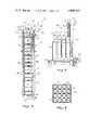
- FIG. 1is a schematic front elevation, partly broken away, of a preferred embodiment of one of the power modules of the improved secondary battery system of the present invention
- FIG. 2is a schematic side elevation, partly broken away and partly in section, of a plurality of the modules of FIG. 1 disposed within a rack and subjected to cooling by a spray tower, a battery-containing rack also being shown during lifting thereof from one of said modules;
- FIG. 3is a schematic top plan view of the modules of FIG. 2 assembled in the rack thereof;
- FIG. 4is a schematic side elevation, partly in cross-section, showing the upper and lower portions of a pile of metal-hydrogen cells constituting a single battery within a shelf in the rack within the module of FIG. 1.
- a module 10which comprises a sealed pressure vessel 12, preferably of generally cylindrical configuration, and having a bottom wall 14, side wall 16 and a removable top cover 18.
- Vessel 12is hollow and is provided with a conduit 20 for the introduction thereinto of hydrogen gas.
- vessel 10is filled with hydrogen gas.
- Vessel 12has disposed therein an elongated, preferably vertical, rack 22 containing a plurality of shelves 24.
- the lower end of rack 22is centered by a projection 25 through plate 26 while the upper end of rack 22 is secured by links 28 to an insulated support bracket 30 connected to the underside of top cover 18.
- Each shelf 24, as more particularly shown in FIG. 4has a central opening 32 therein fitted with a compressible hollow bellows 34 which compresses a pile 35 of cells 36 stacked together within shelf 24 to form battery 38 of said shelf.
- the lower end of bellows 34is positioned within the aligned central openings 40 and 42 of, respectively, an insulator plate 44 and an electrical terminal plate 46 and over the aligned central openings 48 in the stacked pile 35 of cells 36.
- bellows 34together with openings 32, 40, 42 and 48 for the various shelves 24 form a continuous central passageway 50 extending from plate 26 to the upper end 52 of rack 22.
- the intake end 54 of a blower 56is connected to passageway 50.
- Blower 56may include a motor 58 and rotor shaft 60 connected to a fan 62 (FIG. 2) and may be electrically powered as by a conduit 64 extending through cover 18. Blower 56 may be secured to top cover 18, as by a plate 65, or the like.
- FIG. 4a pile of cells 36 is shown within shelf 24 of rack 22 compressed together by bellows 34.
- insulative plate 44for example, of plastic, or the like.
- plate 44an electric terminal plate 46 of nickel, copper, etc.
- cells 36 and plates 44 and 46are generally circular in outline.
- rack 22, as particularly shown in FIG. 1,is spaced inwardly of side wall 16 in vessel 12 so as to provide a peripheral passageway 66 between rack 22 and side wall 16.
- Each cell 36 within pile 35 in shelf 24is spaced from the next adjacent cells 36 by a grid 68 which provides a series of transverse passageways 70 between peripheral passageway 66 and central passageway 50.
- Each grid 64is so arranged that hydrogen can freely pass there through and intimately contact anodic surface 72 of each cell 36 while also acting as a coolant.
- Grids 64have the additional function of electrically interconnecting in series all the cells 36 in pile 35.
- Each cell 36may be formed of any suitable materials which provide an efficient metal-hydrogen cell.
- cathode 74 of each cell 36may comprise a plate formed of nickel powder which has been compressed and sintered to a porous self-supporting condition, and the interstices of which contain active nickel hydroxide.
- the cathode 74 of each cell 36is separated from the anodic surface 72 of that cell by a separator 76 which may comprise a sheet or the like of suitable non-conductive material such as asbestos, or paper or other celluosic fiber material or the like which bears or is impregnated with aqueous potassium hydroxide or other suitable metal-hydrogen electrolyte.
- each cell 36may comprise a metallic (such as nickel) or a non-metallic (such as nylon) screen which has been covered with tetrafluorethylene to leave it in a porous condition and upon which has been deposited a suitable catalyst such as finely divided platinum black powder catalyst as a film or the like.
- a metallicsuch as nickel
- a non-metallicsuch as nylon
- a suitable catalystsuch as finely divided platinum black powder catalyst as a film or the like.
- the hydrogenitself is the true anode while the anodic component 72 provides the catalyst for the reaction.
- Grid 68which is disposed between adjacent cells 36 may comprise any suitable electrically conductive material, for example, corrugated, expanded nickel or other metal, preferably one which is corrosion resistant.
- nickel-hydrogen cells 36are preferred and have been described above, other metal-hydrogen cells known within the art, for example, oxides and oxide mixtures of cobalt, copper, silver, mercury, manganese, chromium and lead, could be used in batteries 38.
- pile 35 of cells 36 within each shelf 24 and constituting a single battery 38is divided into two halves, an upper half above a central terminal plate 78 and a lower half below central terminal plate 78.
- the lower end of pile 35also abuts an electric terminal plate 80 on an insulative plate 82.
- Terminal plates 46 and 80have the same polarity, which polarity is opposite that of central terminal plate 78.
- the cell stacking sequence within the upper half of pile 35 in each shelf 24is opposite to the cell stacking sequence within the lower half of that pile 35, as shown in FIG. 4, so that single central terminal plate 78 can service both halves of pile 35.
- each central terminal plate 78extends to and interconnects with an electrical conduit 84 running outside of rack 22 within vessel 12 along the length thereof and extending outside of vessel 12 through a fitting 86.
- All terminal plates 46 and 80extend to and interconnect with an electrical conduit 88 outside of and running the length of rack 22 in vessel 12 and extending out from vessel 12 through fitting 90.
- modules 10are shown assembled together to form the improved secondary battery system 86 of the present invention.
- the modulespreferably are series connected (not shown).
- Modules 10are disposed within a rack 94 which rests on a water-filled cooling basin 96 provided with a pump 98, suction line 100 and water spray conduit 102 for the application of cooling water spray to the exterior of each vessel 12 in rack 94.
- FIG. 2also shows a rack 22 of a module 10 being lifted out from the top of that module with cover 18 thereof by lines 104 connected to hooks or grommets 106 on cover 18.
- batteries 38 within rack 22can be readily removed, inspected, repaired, replaced, etc.
- blower 56continuously recirculates hydrogen along the desired path in vessel 12.
- Such pathis defined by peripheral passageway 66, transverse passageways 70 and central passageway 50.
- This continuous recirculation of hydrogencauses a heat transfer between cells 36 and the hydrogen and between the hydrogen and the shell (walls 14, 16 and 18) of vessel 12 so as to cool the hydrogen and cells 36. It also sweeps hydrogen continuously into contact with anodic surfaces 72 so as to optimize the operation of cells 36.
- the shell of vessel 12can act as the only cooling means for the hydrogen, by dissipating heat to the atmosphere. However, this cooling effect preferably is amplified through the use of a spray of water on the shell of each vessel 12, as by the operation of pump 98 and conduits 100 and 102 (FIG. 2).
- an internal cooling systemcould be provided within each module 10 (not shown). Such system could include, for example, cooling coils within which a heat transfer medium could be recirculated, as by pumping or the like.
- the improved secondary battery system of the present inventionprovides an optimum design and arrangement for exploiting the valuable properties of metal-hydrogen cells, particularly nickel-hydrogen cells. With this arrangement, each cell 36 is placed in the most favorable environment for its performance. Moreover, the modular system of the present invention allows for indefinite enlargement and expansion of the number of modules so as to be able to accommodate a wide variety of energy demands.
- All active materials of cells 36are recycled indefinitely.
- Each vesselis sealed and of sufficient volume to contain the full charge of hydrogen. Hydrogen is superior to oxygen as a heat transfer and cooling medium. This fact, together with the high efficiency of cells 36, may allow cooling through the vessel shell in place of an internal heat exchanger.
- the temperature of the hydrogenis kept within about 60° F. of that of the atmosphere, preferably by means of the cooling water spray on the exterior of each vessel. It will be noted that cells 36 cannot be overheated or otherwise damaged by overcharge or overdischarge. Moreover, the pressure of the hydrogen in each vessel 12 is a reliable measure of the state of charge. High and low pressure limits can be measured and set to control charging to and discharging from each vessel. Chemically, each cell 36 is stable and not liable to unwanted reactions. The hydrogen in each vessel 12 can circulate freely around the wetted nickel cathodes without adverse effect. Each cell is subject to a low rate of discharge and each battery is relatively immune to atmospheric conditions. The only low temperature cut-off point for the batteries is the freezing point of the electrolyte, usually about minus 40° F. Each cell normally operates at a substantially higher temperature such as 160° F. Modules 10 normally need no weather protection.
- Each battery within each modulemay have 48 cells, each cell operating to produce, for example, 1.304 volts, for a total of 62.5 volts. Each cell may be, for example 28 inches O.D. ⁇ 8.5 inches I.D.
- the cells within each batteryare arranged in series and the 16 modules are series connected to yield a total of 1,000 amps at 1,000 volts. The current output of each battery is 62.5 amps. The output of each module is therefore 1,000 amps at 62.5 volts.
- the improved secondary battery system of the present inventionis suitable for various purposes, as will be apparent. Other advantages of the present system are as set forth in the foregoing.
Landscapes
- Chemical & Material Sciences (AREA)
- Chemical Kinetics & Catalysis (AREA)
- Electrochemistry (AREA)
- General Chemical & Material Sciences (AREA)
- Engineering & Computer Science (AREA)
- Manufacturing & Machinery (AREA)
- Secondary Cells (AREA)
- Hybrid Cells (AREA)
- Battery Mounting, Suspending (AREA)
Abstract
Description
Claims (10)
Priority Applications (10)
| Application Number | Priority Date | Filing Date | Title |
|---|---|---|---|
| US05/787,666US4098962A (en) | 1977-04-14 | 1977-04-14 | Metal-hydrogen secondary battery system |
| GB956178AGB1548557A (en) | 1977-04-14 | 1978-03-10 | Metal-bydrogen secondary battery system |
| IL5444578AIL54445A (en) | 1977-04-14 | 1978-04-04 | Metal-hydrogen secondary battery system |
| CA300,598ACA1111101A (en) | 1977-04-14 | 1978-04-06 | Metal-hydrogen secondary battery system |
| IT4882878AIT1102582B (en) | 1977-04-14 | 1978-04-10 | IMPROVEMENT IN SECONDARY METAL-HYDROGEN BATTERIES |
| BR7802260ABR7802260A (en) | 1977-04-14 | 1978-04-12 | PERFECTED SECONDARY METAL-HYDROGEN BATTERY SYSTEM |
| MX173100AMX149011A (en) | 1977-04-14 | 1978-04-13 | IMPROVED HYDROGEN AND METAL ACCUMULATOR SYSTEM |
| FR7810900AFR2387525A1 (en) | 1977-04-14 | 1978-04-13 | METAL-HYDROGEN ACCUMULATOR ELECTRICAL SUPPLY |
| DE2816054ADE2816054B2 (en) | 1977-04-14 | 1978-04-13 | Metal-hydrogen secondary battery |
| JP53043411AJPS5846833B2 (en) | 1977-04-14 | 1978-04-14 | Metal↓−Hydrogen secondary battery device |
Applications Claiming Priority (1)
| Application Number | Priority Date | Filing Date | Title |
|---|---|---|---|
| US05/787,666US4098962A (en) | 1977-04-14 | 1977-04-14 | Metal-hydrogen secondary battery system |
Publications (1)
| Publication Number | Publication Date |
|---|---|
| US4098962Atrue US4098962A (en) | 1978-07-04 |
Family
ID=25142210
Family Applications (1)
| Application Number | Title | Priority Date | Filing Date |
|---|---|---|---|
| US05/787,666Expired - LifetimeUS4098962A (en) | 1977-04-14 | 1977-04-14 | Metal-hydrogen secondary battery system |
Country Status (10)
| Country | Link |
|---|---|
| US (1) | US4098962A (en) |
| JP (1) | JPS5846833B2 (en) |
| BR (1) | BR7802260A (en) |
| CA (1) | CA1111101A (en) |
| DE (1) | DE2816054B2 (en) |
| FR (1) | FR2387525A1 (en) |
| GB (1) | GB1548557A (en) |
| IL (1) | IL54445A (en) |
| IT (1) | IT1102582B (en) |
| MX (1) | MX149011A (en) |
Cited By (24)
| Publication number | Priority date | Publication date | Assignee | Title |
|---|---|---|---|---|
| US4159367A (en)* | 1978-06-29 | 1979-06-26 | Yardney Electric Corporation | Hydrogen electrochemical cell and rechargeable metal-hydrogen battery |
| US4215187A (en)* | 1977-09-23 | 1980-07-29 | Varta Batterie Aktiengesellschaft | Gas-tight galvanic cell |
| US4327158A (en)* | 1980-08-15 | 1982-04-27 | Eic Laboratories, Inc. | Metal/gas battery |
| US4411970A (en)* | 1981-11-16 | 1983-10-25 | Ford Aerospace & Communications Corporation | Equalizing battery cell busbar |
| US4420545A (en)* | 1981-11-05 | 1983-12-13 | Ford Aerospace & Communications Corporation | Lightweight metal-gas battery |
| EP0140463A1 (en)* | 1983-08-24 | 1985-05-08 | Eagle-Picher Industries, Inc. | Lightweight metal-hydrogen cell with improved plate stack supporting means |
| EP0114484A3 (en)* | 1983-01-21 | 1985-07-31 | Yardney Electric Corporation | Improved rechargeable lead-hydrogen electrical cell |
| WO1985004287A1 (en)* | 1984-03-12 | 1985-09-26 | Hughes Aircraft Company | Nickel-hydrogen bipolar battery |
| US4565749A (en)* | 1984-12-26 | 1986-01-21 | Ford Aerospace & Communications Corporation | Lightweight bipolar metal-gas battery |
| US4578324A (en)* | 1984-10-05 | 1986-03-25 | Ford Aerospace & Communications Corporation | Active cooling system for electrochemical cells |
| US4614025A (en)* | 1984-12-26 | 1986-09-30 | Ford Aerospace & Communications Corporation | Method for making a lightweight bipolar metal-gas battery |
| EP0136769A3 (en)* | 1983-10-03 | 1986-10-08 | Eagle-Picher Industries, Inc. | Metal-gas cell with electrolyte reservoir |
| EP0384945A1 (en)* | 1989-02-28 | 1990-09-05 | Matsushita Electric Industrial Co., Ltd. | Sealed alkaline storage battery and method of producing negative electrode thereof |
| US5071652A (en)* | 1990-12-11 | 1991-12-10 | Globe-Union Inc. | Metal oxide hydrogen battery having improved heat transfer properties |
| US5082754A (en)* | 1990-05-24 | 1992-01-21 | Globe-Union Inc. | Pressure vessel construction for a metal oxide-hydrogen battery |
| EP0449511A3 (en)* | 1990-03-30 | 1992-05-27 | Communications Satellite Corporation | Battery |
| US5354630A (en)* | 1992-12-10 | 1994-10-11 | Comsat | Ni-H2 battery having improved thermal properties |
| US5395708A (en)* | 1994-01-14 | 1995-03-07 | Space Systems/Loral, Inc. | Bimodal electric vehicle battery system |
| USD427964S (en)* | 1999-08-23 | 2000-07-11 | Eveready Battery Company, Inc. | Electrochemical cell |
| US20030008205A1 (en)* | 2001-07-04 | 2003-01-09 | Nissan Motor Co., Ltd. | Battery system with excellent controllability for temperature |
| US20090136853A1 (en)* | 1997-07-22 | 2009-05-28 | Blacklight Power, Inc. | Hydride battery |
| US7966945B1 (en)* | 2008-08-05 | 2011-06-28 | Bnsf Railway Company | Isolation and support structures for hydrogen hybrid locomotives and hydrogen hybrid locomotives using the same |
| CN111602264A (en)* | 2018-01-17 | 2020-08-28 | 西门子股份公司 | Method of assembling an energy storage system |
| US20240072338A1 (en)* | 2022-08-29 | 2024-02-29 | EnerVenue Inc. | Nickel-Hydrogen Battery Configurations for Grid-Scale Energy Storage |
Families Citing this family (1)
| Publication number | Priority date | Publication date | Assignee | Title |
|---|---|---|---|---|
| DE3520855C1 (en)* | 1985-06-11 | 1986-09-04 | Deutsche Automobilgesellschaft Mbh, 3000 Hannover | Galvanic cell with press contact |
Citations (6)
| Publication number | Priority date | Publication date | Assignee | Title |
|---|---|---|---|---|
| US3544375A (en)* | 1967-05-22 | 1970-12-01 | Samuel Ruben | Rechargeable fuel cell |
| US3669744A (en)* | 1971-02-25 | 1972-06-13 | Tsenter Boris I | Hermetically sealed nickel-hydrogen storage cell |
| US3834944A (en)* | 1973-09-10 | 1974-09-10 | Yardney International Corp | Multi-cell metal-fluid battery |
| US3850694A (en)* | 1972-11-27 | 1974-11-26 | Communications Satellite Corp | Low pressure nickel hydrogen cell |
| US3867199A (en)* | 1972-06-05 | 1975-02-18 | Communications Satellite Corp | Nickel hydrogen cell |
| US3990910A (en)* | 1972-05-31 | 1976-11-09 | Tyco Laboratories, Inc. | Nickel-hydrogen battery |
Family Cites Families (4)
| Publication number | Priority date | Publication date | Assignee | Title |
|---|---|---|---|---|
| JPS5110340Y2 (en)* | 1971-12-10 | 1976-03-19 | ||
| JPS50161649A (en)* | 1974-06-18 | 1975-12-27 | ||
| US4000350A (en)* | 1975-03-17 | 1976-12-28 | Hughes Aircraft Company | Battery design |
| US3975210A (en)* | 1975-03-27 | 1976-08-17 | The United States Of America As Represented By The Secretary Of The Air Force | Metal-gas battery with axial reactant gas storage cavity |
- 1977
- 1977-04-14USUS05/787,666patent/US4098962A/ennot_activeExpired - Lifetime
- 1978
- 1978-03-10GBGB956178Apatent/GB1548557A/ennot_activeExpired
- 1978-04-04ILIL5444578Apatent/IL54445A/enunknown
- 1978-04-06CACA300,598Apatent/CA1111101A/ennot_activeExpired
- 1978-04-10ITIT4882878Apatent/IT1102582B/enactive
- 1978-04-12BRBR7802260Apatent/BR7802260A/enunknown
- 1978-04-13FRFR7810900Apatent/FR2387525A1/enactiveGranted
- 1978-04-13DEDE2816054Apatent/DE2816054B2/ennot_activeCeased
- 1978-04-13MXMX173100Apatent/MX149011A/enunknown
- 1978-04-14JPJP53043411Apatent/JPS5846833B2/ennot_activeExpired
Patent Citations (6)
| Publication number | Priority date | Publication date | Assignee | Title |
|---|---|---|---|---|
| US3544375A (en)* | 1967-05-22 | 1970-12-01 | Samuel Ruben | Rechargeable fuel cell |
| US3669744A (en)* | 1971-02-25 | 1972-06-13 | Tsenter Boris I | Hermetically sealed nickel-hydrogen storage cell |
| US3990910A (en)* | 1972-05-31 | 1976-11-09 | Tyco Laboratories, Inc. | Nickel-hydrogen battery |
| US3867199A (en)* | 1972-06-05 | 1975-02-18 | Communications Satellite Corp | Nickel hydrogen cell |
| US3850694A (en)* | 1972-11-27 | 1974-11-26 | Communications Satellite Corp | Low pressure nickel hydrogen cell |
| US3834944A (en)* | 1973-09-10 | 1974-09-10 | Yardney International Corp | Multi-cell metal-fluid battery |
Cited By (31)
| Publication number | Priority date | Publication date | Assignee | Title |
|---|---|---|---|---|
| US4215187A (en)* | 1977-09-23 | 1980-07-29 | Varta Batterie Aktiengesellschaft | Gas-tight galvanic cell |
| FR2430102A1 (en)* | 1978-06-29 | 1980-01-25 | Yardney Electric Corp | ELECTRIC ACCUMULATOR AND ACCUMULATOR BATTERY |
| US4159367A (en)* | 1978-06-29 | 1979-06-26 | Yardney Electric Corporation | Hydrogen electrochemical cell and rechargeable metal-hydrogen battery |
| US4327158A (en)* | 1980-08-15 | 1982-04-27 | Eic Laboratories, Inc. | Metal/gas battery |
| US4420545A (en)* | 1981-11-05 | 1983-12-13 | Ford Aerospace & Communications Corporation | Lightweight metal-gas battery |
| US4411970A (en)* | 1981-11-16 | 1983-10-25 | Ford Aerospace & Communications Corporation | Equalizing battery cell busbar |
| EP0114484A3 (en)* | 1983-01-21 | 1985-07-31 | Yardney Electric Corporation | Improved rechargeable lead-hydrogen electrical cell |
| EP0140463A1 (en)* | 1983-08-24 | 1985-05-08 | Eagle-Picher Industries, Inc. | Lightweight metal-hydrogen cell with improved plate stack supporting means |
| EP0136769A3 (en)* | 1983-10-03 | 1986-10-08 | Eagle-Picher Industries, Inc. | Metal-gas cell with electrolyte reservoir |
| WO1985004287A1 (en)* | 1984-03-12 | 1985-09-26 | Hughes Aircraft Company | Nickel-hydrogen bipolar battery |
| US4567119A (en)* | 1984-03-12 | 1986-01-28 | Hughes Aircraft Company | Nickel-hydrogen bipolar battery |
| US4578324A (en)* | 1984-10-05 | 1986-03-25 | Ford Aerospace & Communications Corporation | Active cooling system for electrochemical cells |
| US4565749A (en)* | 1984-12-26 | 1986-01-21 | Ford Aerospace & Communications Corporation | Lightweight bipolar metal-gas battery |
| US4614025A (en)* | 1984-12-26 | 1986-09-30 | Ford Aerospace & Communications Corporation | Method for making a lightweight bipolar metal-gas battery |
| EP0384945A1 (en)* | 1989-02-28 | 1990-09-05 | Matsushita Electric Industrial Co., Ltd. | Sealed alkaline storage battery and method of producing negative electrode thereof |
| US4994334A (en)* | 1989-02-28 | 1991-02-19 | Matsushita Electric Industrial Co., Ltd. | Sealed alkaline storage battery and method of producing negative electrode thereof |
| EP0449511A3 (en)* | 1990-03-30 | 1992-05-27 | Communications Satellite Corporation | Battery |
| US5082754A (en)* | 1990-05-24 | 1992-01-21 | Globe-Union Inc. | Pressure vessel construction for a metal oxide-hydrogen battery |
| US5071652A (en)* | 1990-12-11 | 1991-12-10 | Globe-Union Inc. | Metal oxide hydrogen battery having improved heat transfer properties |
| US5354630A (en)* | 1992-12-10 | 1994-10-11 | Comsat | Ni-H2 battery having improved thermal properties |
| US5395708A (en)* | 1994-01-14 | 1995-03-07 | Space Systems/Loral, Inc. | Bimodal electric vehicle battery system |
| US20090136853A1 (en)* | 1997-07-22 | 2009-05-28 | Blacklight Power, Inc. | Hydride battery |
| USD427964S (en)* | 1999-08-23 | 2000-07-11 | Eveready Battery Company, Inc. | Electrochemical cell |
| US7264902B2 (en)* | 2001-07-04 | 2007-09-04 | Nissan Motor Co., Ltd. | Battery system with excellent controllability for temperature |
| US20030008205A1 (en)* | 2001-07-04 | 2003-01-09 | Nissan Motor Co., Ltd. | Battery system with excellent controllability for temperature |
| US7966945B1 (en)* | 2008-08-05 | 2011-06-28 | Bnsf Railway Company | Isolation and support structures for hydrogen hybrid locomotives and hydrogen hybrid locomotives using the same |
| CN111602264A (en)* | 2018-01-17 | 2020-08-28 | 西门子股份公司 | Method of assembling an energy storage system |
| US11417919B2 (en)* | 2018-01-17 | 2022-08-16 | Siemens Energy AS | Method of assembling an energy storage system |
| CN111602264B (en)* | 2018-01-17 | 2023-04-07 | 西门子能源有限责任公司 | Method of assembling an energy storage system |
| US20240072338A1 (en)* | 2022-08-29 | 2024-02-29 | EnerVenue Inc. | Nickel-Hydrogen Battery Configurations for Grid-Scale Energy Storage |
| US12107249B2 (en)* | 2022-08-29 | 2024-10-01 | EnerVenue Inc. | Nickel-hydrogen battery configurations for grid-scale energy storage |
Also Published As
| Publication number | Publication date |
|---|---|
| BR7802260A (en) | 1979-02-13 |
| JPS5846833B2 (en) | 1983-10-19 |
| IT7848828A0 (en) | 1978-04-10 |
| DE2816054A1 (en) | 1978-10-26 |
| CA1111101A (en) | 1981-10-20 |
| IL54445A (en) | 1981-01-30 |
| DE2816054B2 (en) | 1981-04-16 |
| IL54445A0 (en) | 1978-07-31 |
| FR2387525B1 (en) | 1981-12-24 |
| JPS53128734A (en) | 1978-11-10 |
| GB1548557A (en) | 1979-07-18 |
| IT1102582B (en) | 1985-10-07 |
| MX149011A (en) | 1983-08-08 |
| FR2387525A1 (en) | 1978-11-10 |
Similar Documents
| Publication | Publication Date | Title |
|---|---|---|
| US4098962A (en) | Metal-hydrogen secondary battery system | |
| US20240145827A1 (en) | Rolling diaphragm seal | |
| US3338746A (en) | Low-temperature fuel cell in combination with a power accumulator | |
| Öjefors et al. | An iron—air vehicle battery | |
| EP1428272B1 (en) | A bipolar battery and a biplate assembly | |
| US3359136A (en) | Rechargeable energy conversion system | |
| WO2007080456A2 (en) | Electrochemical cell for hybrid electric vehicle applications | |
| US4957830A (en) | Rechargeable metal oxide-hydrogen battery | |
| US3834944A (en) | Multi-cell metal-fluid battery | |
| US20170062884A1 (en) | Energy storage device with reduced temperature variability between cells | |
| EP2869383A1 (en) | Large-capacity power storage device | |
| EP3422454A1 (en) | Bipolar battery | |
| US8748052B2 (en) | Reversible fuel cell | |
| EP3249731A1 (en) | Subsea uninterruptible power supply | |
| EP4354690A1 (en) | Electricity storage system | |
| JP3474919B2 (en) | Stacked sealed nickel-hydride battery | |
| US3463673A (en) | Electrochemical coulometer and method of forming same | |
| CN211700449U (en) | Box type flow battery unit | |
| US20100207570A1 (en) | Rapid charge transportation battery | |
| CN1178398A (en) | Cooling method of batteries | |
| US10511044B2 (en) | Alkaline hybrid redox flow battery with high energy density | |
| CN222620055U (en) | Battery connection structure capable of realizing multistage parallel use | |
| Gutzeit | Batteries for telecommunications systems powered by solar energy | |
| JP3573892B2 (en) | Assembled battery | |
| EP3561930B1 (en) | Redox flow battery |
Legal Events
| Date | Code | Title | Description |
|---|---|---|---|
| AS | Assignment | Owner name:WHITTAKER TECHNICAL PRODUCTS, INC. Free format text:CHANGE OF NAME;ASSIGNOR:YARDNEY CORPORATION;REEL/FRAME:005390/0314 Effective date:19870416 Owner name:YARDNEY CORPORATION Free format text:CHANGE OF NAME;ASSIGNOR:YARDNEY ELECTRIC CORPORATION;REEL/FRAME:005390/0321 Effective date:19830428 | |
| AS | Assignment | Owner name:WHITTAKER TECHNICAL PRODUCTS, INC. Free format text:CHANGE OF NAME;ASSIGNOR:YARDNEY CORPORATION;REEL/FRAME:005264/0184 Effective date:19870416 | |
| AS | Assignment | Owner name:SECURITY PACIFIC NATIONAL BANK Free format text:SECURITY INTEREST;ASSIGNOR:WHITTAKER TECHNICAL PRODUCTS, INC.;REEL/FRAME:005152/0027 Effective date:19890628 | |
| AS | Assignment | Owner name:YARDNEY CORPORATION Free format text:CHANGE OF NAME;ASSIGNOR:YARDNEY ELECTRIC CORPORATION;REEL/FRAME:005268/0469 Effective date:19830428 | |
| AS | Assignment | Owner name:YARDNEY TECHNICAL PRODUCTS, INC., A CORP. OF DE., Free format text:ASSIGNMENT OF ASSIGNORS INTEREST.;ASSIGNOR:WHITTAKER TECHNICAL PRODUCTS, INC., A CORP. OF NY.;REEL/FRAME:005323/0383 Effective date:19900511 | |
| AS | Assignment | Owner name:BANK OF NEW YORK, THE Free format text:SECURITY INTEREST;ASSIGNOR:YARDNEY TECHNICAL PRODUCTS, INC., A CORP. OF DE.;REEL/FRAME:005390/0067 Effective date:19900511 Owner name:WHITTAKER TECHNICAL PRODUCTS, INC., A NY CORP. Free format text:RELEASED BY SECURED PARTY;ASSIGNOR:SECURITY PACIFIC NATIONAL BANK;REEL/FRAME:005390/0084 Effective date:19900511 | |
| AS | Assignment | Owner name:WHITTAKER TECHNICAL PRODUCTS, INC., CALIFORNIA Free format text:RELEASED BY SECURED PARTY;ASSIGNOR:SECURITY PACIFIC NATIONAL BANK;REEL/FRAME:005456/0751 Effective date:19900605 |