US4087781A - Electromagnetic lithosphere telemetry system - Google Patents
Electromagnetic lithosphere telemetry systemDownload PDFInfo
- Publication number
- US4087781A US4087781AUS05/682,417US68241776AUS4087781AUS 4087781 AUS4087781 AUS 4087781AUS 68241776 AUS68241776 AUS 68241776AUS 4087781 AUS4087781 AUS 4087781A
- Authority
- US
- United States
- Prior art keywords
- signal
- oil well
- signals
- combination
- earth
- Prior art date
- Legal status (The legal status is an assumption and is not a legal conclusion. Google has not performed a legal analysis and makes no representation as to the accuracy of the status listed.)
- Expired - Lifetime
Links
- 239000003129oil wellSubstances0.000claimsabstractdescription42
- 230000005540biological transmissionEffects0.000claimsabstractdescription25
- 230000010363phase shiftEffects0.000claimsabstractdescription4
- 238000005259measurementMethods0.000claimsdescription17
- 238000000034methodMethods0.000claimsdescription6
- 230000035699permeabilityEffects0.000claimsdescription3
- 230000003213activating effectEffects0.000claimsdescription2
- 230000004044responseEffects0.000claimsdescription2
- 230000000977initiatory effectEffects0.000claims6
- 230000005670electromagnetic radiationEffects0.000claims3
- 238000005553drillingMethods0.000abstractdescription54
- 230000003247decreasing effectEffects0.000abstract1
- 239000010410layerSubstances0.000description12
- 239000003990capacitorSubstances0.000description5
- 230000003111delayed effectEffects0.000description5
- 238000010586diagramMethods0.000description5
- 230000004048modificationEffects0.000description5
- 238000012986modificationMethods0.000description5
- 230000008878couplingEffects0.000description4
- 238000010168coupling processMethods0.000description4
- 238000005859coupling reactionMethods0.000description4
- 230000008929regenerationEffects0.000description4
- 238000011069regeneration methodMethods0.000description4
- 229910000831SteelInorganic materials0.000description3
- 239000004020conductorSubstances0.000description3
- 239000010959steelSubstances0.000description3
- 238000013500data storageMethods0.000description2
- 230000006870functionEffects0.000description2
- 230000006698inductionEffects0.000description2
- 230000010355oscillationEffects0.000description2
- 238000012545processingMethods0.000description2
- 230000009467reductionEffects0.000description2
- 239000004576sandSubstances0.000description2
- XLYOFNOQVPJJNP-UHFFFAOYSA-NwaterSubstancesOXLYOFNOQVPJJNP-UHFFFAOYSA-N0.000description2
- RYGMFSIKBFXOCR-UHFFFAOYSA-NCopperChemical compound[Cu]RYGMFSIKBFXOCR-UHFFFAOYSA-N0.000description1
- 230000004913activationEffects0.000description1
- 230000004075alterationEffects0.000description1
- 230000003321amplificationEffects0.000description1
- 230000008901benefitEffects0.000description1
- 230000015572biosynthetic processEffects0.000description1
- 238000004364calculation methodMethods0.000description1
- 230000008859changeEffects0.000description1
- 238000006243chemical reactionMethods0.000description1
- 238000010276constructionMethods0.000description1
- 239000000356contaminantSubstances0.000description1
- 230000007423decreaseEffects0.000description1
- 230000005672electromagnetic fieldEffects0.000description1
- 238000001914filtrationMethods0.000description1
- 239000012530fluidSubstances0.000description1
- 238000005755formation reactionMethods0.000description1
- 238000003199nucleic acid amplification methodMethods0.000description1
- 238000004806packaging method and processMethods0.000description1
- 239000011435rockSubstances0.000description1
- 230000035945sensitivityEffects0.000description1
- 239000002689soilSubstances0.000description1
- 238000013517stratificationMethods0.000description1
- 239000000758substrateSubstances0.000description1
- 239000002344surface layerSubstances0.000description1
- 230000001960triggered effectEffects0.000description1
- 238000004804windingMethods0.000description1
Images


Classifications
- E—FIXED CONSTRUCTIONS
- E21—EARTH OR ROCK DRILLING; MINING
- E21B—EARTH OR ROCK DRILLING; OBTAINING OIL, GAS, WATER, SOLUBLE OR MELTABLE MATERIALS OR A SLURRY OF MINERALS FROM WELLS
- E21B47/00—Survey of boreholes or wells
- E21B47/12—Means for transmitting measuring-signals or control signals from the well to the surface, or from the surface to the well, e.g. for logging while drilling
- E21B47/13—Means for transmitting measuring-signals or control signals from the well to the surface, or from the surface to the well, e.g. for logging while drilling by electromagnetic energy, e.g. radio frequency
Definitions
- the inventionrelates to telemetry of information through the earth's lithosphere. It is particularly adapted for telemetry of information from the bottom of an oil well to the surface of the earth during oil well drilling operations.
- the information telemeteredmay include but is not limited to the parameters of pressure, temperature, salinity, direction and deviation of the well bore, bit conditions, and logging data including resistivity of the various layers, sonic density, porosity, induction, self potential, and pressure gradients.
- the earthitself formed the other conductor.
- the conductivity of the earthis unpredictable and is frequently too low to make such a system practical at typical oil well depths.
- Both types of such systemssuffered the additional common problem that the conductivity between pipe sections is greatly affected by the presence of contaminants on the pipe joints. Frequently the resistance of the pipe joints was too high to permit telemetry using any practical power levels.
- a telemetry systemin which the relevant parameters are measured by sensors located in the vicinity of the drill bit in a well bottom telemetry station. The outputs of the sensors are digitized and stored until transmission is triggered by a signal arriving via lithospheric propagation from a surface station. Transmission from well bottom to surface of telemetry data is normally performed during the pauses of the drilling string rotation. However, selected narrow-band emergency messages such as "Alarm of impending blow-out" can be automatically transmitted from the well bottom without the need of a triggering signal from the surface station, and while full rotation of the drilling string is underway. Transmission uses an ELF (3-3000 Hz) or ULF (0.03-3 Hz) carrier, preferably in the range of 1-30 Hz.
- Phase shift modulationis preferred.
- the electromagnetic carrierpropagates via lithospheric paths.
- Repeater stationsare located along the length of the drill pipe as required. In a preferred embodiment, 1 kilometer spacing is used between stations.
- a transceiverincluding a transmitter and receiver operating preferably upon the same frequency as the well bottom station transmitter.
- the signal to be relayed by the repeater stationis received, delayed by one or more bit time periods to prevent regeneration with the well bottom station and other repeater stations.
- the signalis retransmitted upon the same frequency.
- the well bottom and repeater stationsare located in specially modified drill pipe sections which mechanically couple to the other drill pipe sections without special modifications to the other drill pipe sections.
- antennaspreferably with high permeability core are used for both transmitting and receiving. These are also located inside the special drilling pipe sections.
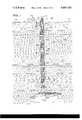
- FIG. 1is a cross-sectional view of an oil well embodying a telemetry system in accordance with the present invention
- FIG. 2is a cross-sectional view of a repeater section
- FIG. 3is a cross-sectional view taken along the drill pipe section of FIG. 3 showing the preferred mounting of the antennas;
- FIG. 4is a block diagram of the well bottom telemetry station.
- FIG. 5is a block diagram of a repeater station.
- FIG. 1a cross-sectional view of an oil well and surrounding lithospheric layers through which oil well 100 is drilled.
- Oil well 100may pass, for example, through top soil layer 102, first shale layer 104, gravel layer 106, first sand layer 108, second shale layer 110, and second sand layer 112.
- Oil well pool 116 towards which oil well 100 is aimedis located beneath third shale layer 114.
- Drilling pipe assembly 125is made up of numerous drilling pipe sections 124 which are screwed together with tool joints and assembled one-by-one as the oil well progresses downward.
- Casing pipe assembly 121is used to keep the surrounding layers from caving into the oil well hole and to prevent unwanted water and other fluids from entering the well.
- Casing pipe assembly 121is made up of individual casing sections 122 which are screwed together and pushed downward surrounding drilling pipe assembly 125. Both casing sections 122 and drilling pipe sections 124 are made of high strength steel. The same type of casing sections and drilling pipe sections are used with the present invention as have previously been used. No modifications are required for the present invention to function properly.
- Drilling mud 130lubricates drilling bit 132 and conveys drilled away debris upwards to the surface in the space between drilling pipe assembly 125 and casing pipe assembly 121.
- different types of drilling mudare used. In some oil well situations it has been found advantageous to employ water rather than mud.
- well-bottom station 140including therein parameter sensors, digitizing circuitry, and telemetry transmitter. There is one sensor present in well bottom station 140 for each parameter to be measured. These parameters include but are not limited to pressure, temperature, salinity, direction and deviation of well bore, bit conditions and logging data including resistivity, sonic density, porosity, induction, self potential and pressure gradients. With knowledge of these parameters one skilled in the art is able to make numerous determinations about the oil well.
- a triggering signalis transmitted to the bottom of oil well 100 and received at well bottom station 140 through antenna 142.
- a single turn loop 120 surrounding oil well 100is activated with a signal in the ELF/ULF range of 1-30 Hz.
- the activating signalis produced at surface station 150.
- the activation of single turn loop 120produces an electromagnetic field as indicated by field lines 148.
- the triggering signalreaches the bottom of oil well 100 without amplification by intervening repeater stations because of the relative ease in obtaining higher power levels on the surface and because the level of noise present in the lithosphere generally decreases with depth in the earth.
- the stored digitized sensor outputsare transmitted upon a ELF/ULF carrier in the range of 1-30 Hz.
- the sensor datais transmitted one bit at a time in serial fashion. For example, if the output of one of the sensors in digital form is made up of six bits, those six bits are transmitted one at a time until all six have been transmitted. Phase shift modulation is preferred although other types of modulation may be used as well.
- An identifying codecan be transmitted before the start of data transmission from each of the sensors to indicate which of the parameters is then being transmitted.
- Such an encoding schemeincludes one wherein the desired parameter to be transmitted is determined by the number of cycles of the triggering signals sent from the surface.
- transmissionis accomplished during times in which the drill bit is not rotating.
- the drill bitwas stopped periodically for 2 minute transmission intervals. It was found that bit rates from one to 10 bits per second were attainable. With these bit rates it is possible in the 2 minute interval to transmit 120 to 1200 bits respectively. If, for example, the total number of bits stored for all sensor outputs is 300, three such intervals are more than sufficient for transmission of the entire 300 bits at the one bit per second rate. Only one 2 minute interval is required for bit rates of 2.5 bits per second or greater.
- Solenoidal antennas 142have the same structure as those shown in FIGS. 2 and 3 in conjunction with the discussion below of repeater sections 126.
- Repeater sections 126 including therein repeater stations 144are spaced at predetermined intervals along the drilling pipe. Repeater sections 126 mate at each end with drilling pipe sections 124 and form an integral part of drilling pipe assembly 125. Drilling mud 130 flows through and around repeater sections 126 the same as through and around drilling pipe sections 124.
- the interval between repeater sections 126will of course be determined by the electromagnetic characteristics of the formations encountered and the transmitting power and receiver sensitivity of each section. In the preferred embodiment, a spacing of 1 kilometer using a transmitter power of 100 watts has been found to be satisfactory for most values of the layer conductivity expected in the drilled stratification.
- the total number of repeater stations usedwill of course depend upon the overall depth of the well, only one repeater section 126 being shown in FIG. 1 for clarity.
- Repeater section 126performs three basic functions. First, it receives and amplifies the signals transmitted from the station next below it whether that station be another repeater station 144 or well bottom station 140. Secondly, the received and amplified signal is delayed by one or more bit period times to insure against regeneration or oscillation between repeater sections. Thirdly, repeater section 126 retransmits the received, amplified and delayed signal to the next station above.
- the signals reaching the surface layer 102are intercepted by surface station antenna 152 and coupled therefrom to surface station 150.
- the received signalsare demodulated and converted to a preferred form for further processing.
- Surface station 150may include data storage and computer circuitry for performing calculations upon the received and demodulated signals.
- surface station 150can include data storage circuitry such as a digital magnetic tape recorder so that the received data may be recorded and transported elsewhere for further processing.
- FIG. 2is shown a cross sectional view of a repeater section 126.
- Repeater section 126is constructed of high strength steel casing 200 including therein cavity 202 which contains repeater station 144.
- Repeater section 144includes three major components: solenoid antenna 146, transceiver 145 and batteries 204.
- Access cover 210is provided on the outer surface of casing 200 above batteries 204 to permit access to and replacement of batteries 204.
- the type of steel used and the wall thicknesses employed around cavity 202are chosen so that the overall mechanical strength of repeater section 126 will be the same as its adjacent sections of drilling pipe 124. This may result in some reduction of internal and external spaces available for flow of drilling mud. However, since the reduction will be modest and since the repeater stations are spaced as far apart as 1 kilometer or more, the total added resistance to the flow of drilling mud by the addition of repeater sections 126 will be minimal.
- Antenna 146is constructed of a number of parallel long high permeability rods around which is wrapped a number of turns of copper wire. In the preferred embodiment shown in cross-sectional view of FIG. 3, six of these rods are used although in practice any number could be employed. In the preferred embodiment, each rod is approximately 1 inch thick, 2 inches in width, and 20 feet in length. Winding 206 is coupled at each end to transceiver 145.
- FIG. 5is shown a block diagram of a preferred version of transceiver 144.
- Antenna 146is connected in series with capacitor 504, the combination resonating at the chosen transmitting and receiving frequency of the system.
- antenna 146 and resonating capacitor 504are coupled through double-pole double-throw switch 506 to receiver 508.
- receiver 508amplifies the signal on its input leads and couples the amplified signal to delay circuit 510.
- receiver 508first amplifies the signal then demodulates it to its original digital form and assembles the bits to a complete message.
- the assembled messageis then digitally "recognized” by comparison with a number of stored pre-coded messages, there being one such message for every possible message transmitted.
- a number of stored pre-coded messagesthere being one such message for every possible message transmitted.
- any number of different “recognition” schemescan be used, depending upon the expected quality of the intercepted signals and the required overall reliability of message transmission from well bottom to surface.
- the output of receiver 508is delayed by delay circuit 510 to prevent regeneration or oscillation between repeater stations 144 or well bottom station 128 or surface station 150.
- the delayed outputmodulates the signal from local oscillator 516 at modulator 514.
- local oscillator 516operates at the same frequency as each of the other repeater stations 144 and well bottom station 140.
- One advantage in operating each section at the same transmitting frequencyis that identical repeater sections can be used along the oil well. Adjustments and frequency changes need not be made for each individual section. However, it is possible to construct a system in accordance with the present invention using different frequencies at each station.
- Transmitter 512amplifies the modulated signal from modulator 514. During transmission times switch 506 couples antenna 146 to the output terminals of transmitter 512.
- Batteries 210supply operating power to all circuits within repeater station 144. Batteries 210 are preferably of the lithium-organic compound type although any battery type capable of supplying sufficient power over the required time period of the temperature encountered in the oil well will suffice as well. Batteries 210 may be tested and replaced if necessary each time the oil well drilling pipe is removed from the well to change the drilling bit.
- FIG. 4is shown a block diagram of a preferred embodiment of the electronics portion of well bottom section 128.
- Sensors 402-1 through 402-Nare provided one for each desired parameter set forth above. These parameters are sensed during full rotation of the drilling string.
- Analog-to-digital converters 404are coupled to each output of sensors 402-1 to 402-N. The analog to digital conversion is carried out to as many binary bits as necessary to obtain the desired measurement accuracy of the relevant parameters.
- the digitized measurementsare stored in digital storage register 406 prior to transmission.
- double-pole double-throw switch 420couples antenna 142 and series resonating capacitor 422 to the input terminals of receiver 414.
- the series combination of resonating capacitor 422 and antenna 142resonates at the predetermined operating frequency of the system.
- Receiver 414detects and amplifies the triggering signal sent from the surface. The demodulated output of receiver 414 causes decoder 412 to begin advancing.
- Multiplexer 408responds to the count input by coupling a corresponding input bit line to its output. Each digitized parameter measurement corresponds to a predetermined sequence of adjacent counts. If the triggering signal is encoded to indicate which parameter measurement is to be transmitted, decoder 412 produces as its output a binary number corresponding to the first bit of the desired measurement. A count sequence is commenced with this binary number which continues until the last bit of the measurement has been transmitted. Multiplexer 408 operates in response to the output of decoder 412 to couple the digital outputs of register 406 to the input of modulator 416. Each digitized measurement is coupled in sequence one bit at a time. An identifying code may be attached to and transmitted before the transmission of each digitized message.
- Local oscillator 415, modulator 416, and transmitter 418operate the same as the equivalent circuitry of repeater section 126 as shown in FIG. 5. During transmission times the output terminals of transmitter 418 are coupled through switch 420 to resonating capacitor 422 and antenna 142. Transmission of the telemetry data takes place during the drilling pauses.
- a repeater stationremains in the receiving mode while the station next below is transmitting one or more message bits. That repeater station switches to the transmitting mode as soon as the station next below has completed transmission of the message bits and retransmits the same message bits before the station next below transmits further message bits in the sequence.
- the packaging of well bottom repeater section circuitryis the same or similar to that done for repeater section 126.
- the same type of pipe section with cavity providedmay be used to package repeater section 128.
- the same antenna constructionmay be used.
- other types of well bottom transmission schemescould be used as well, the circuitry of the block diagram of FIG. 4 being by way of illustration only. For example, each measured parameter could be transmitted separately upon a different frequency.
- an internal power generatormay be used which derives its operating force from the flow of drilling mud.
Landscapes
- Engineering & Computer Science (AREA)
- Physics & Mathematics (AREA)
- Mining & Mineral Resources (AREA)
- Remote Sensing (AREA)
- Life Sciences & Earth Sciences (AREA)
- Geology (AREA)
- Geophysics (AREA)
- Environmental & Geological Engineering (AREA)
- Fluid Mechanics (AREA)
- Electromagnetism (AREA)
- General Life Sciences & Earth Sciences (AREA)
- Geochemistry & Mineralogy (AREA)
- Arrangements For Transmission Of Measured Signals (AREA)
Abstract
Description
This is a continuation of application Ser. No. 484,638, filed July 1, 1974, now abandoned.
1. Field of the Invention
The invention relates to telemetry of information through the earth's lithosphere. It is particularly adapted for telemetry of information from the bottom of an oil well to the surface of the earth during oil well drilling operations. The information telemetered may include but is not limited to the parameters of pressure, temperature, salinity, direction and deviation of the well bore, bit conditions, and logging data including resistivity of the various layers, sonic density, porosity, induction, self potential, and pressure gradients.
2. Description on the Prior Art
In previous oil well telemetry systems when it was desired to make measurements of important parameters at the bottom of the oil well, it was first necessary to pull up the drilling pipe section by section including the drilling bit to completely vacate the drilled hole. Sensors were then lowered down to the bottom of the well on a connected wire, the measurements were taken, the sensors and wire removed, and finally the bit and drilling pipe reassembled and put back into the hole. Obviously, such procedures were extremely expensive and time consuming since drilling operations had to be ceased each time measurements were to be made.
These problems have led to numerous attempts at oil well telemetry in which the drilling pipe and bit do not have to be removed from the well before measurements are made. Attempts have been made to telemeter data by means of sonic waves traveling through either the drilling pipe or through the drilling mud present both inside and surrounding the drilling pipe. Unfortunately, the drilling mud proved to be a strong sonic damper which destroyed the sonic waves before they could travel very far. Total depth attainable for telemetry with such systems was much smaller than minimally needed in a practical system.
Further attempts included installing a bifilar electric line either inside or outside of the drilling pipe or the casing pipe. Unfortunately, the mechanical stresses inside the well and the rocks and other debris brought up from the bottom of the well frequently destroyed the wire.
Another attempted system included a conductor inside of each section of drill pipe with transformer coupling between sections of pipe. Besides requiring expensive modifications to the drill pipe these systems proved unreliable in that magnetic coupling between sections was frequently hindered by mechanical misalignment between drill pipe sections and because of the attendant difficulty of aligning coupling coils with one another.
Still further attempts included one in which either the drilling pipe or casing pipe was used as one of the conductors in an electrical transmission system. In one such system, the earth itself formed the other conductor. Unfortunately, the conductivity of the earth is unpredictable and is frequently too low to make such a system practical at typical oil well depths. Still further such systems included a single wire along the casing pipe or drilling pipe. Such systems suffered from the problems discussed above with the bifilar type wire system. Both types of such systems suffered the additional common problem that the conductivity between pipe sections is greatly affected by the presence of contaminants on the pipe joints. Frequently the resistance of the pipe joints was too high to permit telemetry using any practical power levels.
Accordingly, it is an object of the present invention to provide an oil well telemetry system in which the drilling pipe and drilling bit need not be removed from the oil well each time parameter measurements are to be made.
Furthermore, it is an object of the present invention to provide a system in which telemetry from the bottom of an oil well can be accomplished reliably unaffected by the resistance of the drilling pipe and casing pipe.
Moreover, it is an object of the present invention to provide an oil well telemetry system which operates within a wide range of values of the resistivity of the various layers of earth through which the oil well is bored.
Also, it is an object of the present invention to provide an oil well telemetry system which does not require modifications to every section of drilling pipe.
These as well as other objects may be met by a telemetry system in which the relevant parameters are measured by sensors located in the vicinity of the drill bit in a well bottom telemetry station. The outputs of the sensors are digitized and stored until transmission is triggered by a signal arriving via lithospheric propagation from a surface station. Transmission from well bottom to surface of telemetry data is normally performed during the pauses of the drilling string rotation. However, selected narrow-band emergency messages such as "Alarm of impending blow-out" can be automatically transmitted from the well bottom without the need of a triggering signal from the surface station, and while full rotation of the drilling string is underway. Transmission uses an ELF (3-3000 Hz) or ULF (0.03-3 Hz) carrier, preferably in the range of 1-30 Hz.
Phase shift modulation is preferred. The electromagnetic carrier propagates via lithospheric paths. Repeater stations are located along the length of the drill pipe as required. In a preferred embodiment, 1 kilometer spacing is used between stations. At each repeater station there is located a transceiver including a transmitter and receiver operating preferably upon the same frequency as the well bottom station transmitter.
The signal to be relayed by the repeater station is received, delayed by one or more bit time periods to prevent regeneration with the well bottom station and other repeater stations. The signal is retransmitted upon the same frequency.
In the preferred embodiment, the well bottom and repeater stations are located in specially modified drill pipe sections which mechanically couple to the other drill pipe sections without special modifications to the other drill pipe sections. Also in the preferred embodiment, antennas preferably with high permeability core are used for both transmitting and receiving. These are also located inside the special drilling pipe sections.
FIG. 1 is a cross-sectional view of an oil well embodying a telemetry system in accordance with the present invention;
FIG. 2 is a cross-sectional view of a repeater section;
FIG. 3 is a cross-sectional view taken along the drill pipe section of FIG. 3 showing the preferred mounting of the antennas;
FIG. 4 is a block diagram of the well bottom telemetry station; and
FIG. 5 is a block diagram of a repeater station.
In FIG. 1 is shown a cross-sectional view of an oil well and surrounding lithospheric layers through which oil well 100 is drilled. Oil well 100 may pass, for example, throughtop soil layer 102,first shale layer 104,gravel layer 106, first sand layer 108,second shale layer 110, andsecond sand layer 112.Oil well pool 116 towards which oil well 100 is aimed is located beneaththird shale layer 114.
The actual drilling is performed bydrill bit 132 located at the end ofdrilling pipe assembly 125.Drilling pipe assembly 125 is made up of numerousdrilling pipe sections 124 which are screwed together with tool joints and assembled one-by-one as the oil well progresses downward.
Drilling mud from an external supply, not shown, is forced downward through the hole in the center ofdrilling pipe assembly 125 to the bottom of the oil well and to the region surroundingdrilling bit 132.Drilling mud 130 lubricatesdrilling bit 132 and conveys drilled away debris upwards to the surface in the space betweendrilling pipe assembly 125 andcasing pipe assembly 121. Depending upon the types of formatons encountered, different types of drilling mud are used. In some oil well situations it has been found advantageous to employ water rather than mud.
At the bottom ofoil well 100 in the drilling pipe section attached todrilling bit 132 is located well-bottom station 140 including therein parameter sensors, digitizing circuitry, and telemetry transmitter. There is one sensor present in wellbottom station 140 for each parameter to be measured. These parameters include but are not limited to pressure, temperature, salinity, direction and deviation of well bore, bit conditions and logging data including resistivity, sonic density, porosity, induction, self potential and pressure gradients. With knowledge of these parameters one skilled in the art is able to make numerous determinations about the oil well. These include the speed at which the well should be drilled, the type of drilling mud to be employed, the length of time remaining before the drilling bit needs to be changed, the direction at which the well is being drilled, as well as the present likelihood of striking oil as indicated by the parameters of the surrounding substrates. Moreover, the speed at which these parameters are obtained is a large factor in determining the overall cost of the drilling of the oil well. It will be demonstrated that with the present invention the speed at which these parameters may be obtained by one on the surface is much faster than has hitherto been obtainable with prior art telemetry systems.
When it is desired to initiate transmission of data from the bottom ofoil well 100, a triggering signal is transmitted to the bottom ofoil well 100 and received at wellbottom station 140 throughantenna 142. To transmit the triggering signal asingle turn loop 120 surroundingoil well 100 is activated with a signal in the ELF/ULF range of 1-30 Hz. The activating signal is produced atsurface station 150. The activation ofsingle turn loop 120 produces an electromagnetic field as indicated byfield lines 148. The triggering signal reaches the bottom ofoil well 100 without amplification by intervening repeater stations because of the relative ease in obtaining higher power levels on the surface and because the level of noise present in the lithosphere generally decreases with depth in the earth.
Upon reception of the triggering signal transmitted from the surface, the stored digitized sensor outputs are transmitted upon a ELF/ULF carrier in the range of 1-30 Hz. The sensor data is transmitted one bit at a time in serial fashion. For example, if the output of one of the sensors in digital form is made up of six bits, those six bits are transmitted one at a time until all six have been transmitted. Phase shift modulation is preferred although other types of modulation may be used as well.
An identifying code can be transmitted before the start of data transmission from each of the sensors to indicate which of the parameters is then being transmitted. Alternatively, it is possible to encode the triggering signal from the surface so that only a specific one or group of the stored parameters is transmitted for the particular code then present upon the triggering signal. Such an encoding scheme includes one wherein the desired parameter to be transmitted is determined by the number of cycles of the triggering signals sent from the surface.
In the preferred embodiment transmission is accomplished during times in which the drill bit is not rotating. In one preferred embodiment operating with a carrier frequency of 24 Hz, the drill bit was stopped periodically for 2 minute transmission intervals. It was found that bit rates from one to 10 bits per second were attainable. With these bit rates it is possible in the 2 minute interval to transmit 120 to 1200 bits respectively. If, for example, the total number of bits stored for all sensor outputs is 300, three such intervals are more than sufficient for transmission of the entire 300 bits at the one bit per second rate. Only one 2 minute interval is required for bit rates of 2.5 bits per second or greater.
Transmission and reception is accomplished at wellbottom station 140 throughsolenoidal antennas 142.Solenoidal antennas 142 have the same structure as those shown in FIGS. 2 and 3 in conjunction with the discussion below ofrepeater sections 126.
The signals reaching thesurface layer 102 are intercepted bysurface station antenna 152 and coupled therefrom tosurface station 150. Atsurface station 150 the received signals are demodulated and converted to a preferred form for further processing.Surface station 150 may include data storage and computer circuitry for performing calculations upon the received and demodulated signals. Of course,surface station 150 can include data storage circuitry such as a digital magnetic tape recorder so that the received data may be recorded and transported elsewhere for further processing.
In FIG. 2 is shown a cross sectional view of arepeater section 126.Repeater section 126 is constructed of highstrength steel casing 200 including thereincavity 202 which containsrepeater station 144.Repeater section 144 includes three major components:solenoid antenna 146,transceiver 145 andbatteries 204.Access cover 210 is provided on the outer surface ofcasing 200 abovebatteries 204 to permit access to and replacement ofbatteries 204. The type of steel used and the wall thicknesses employed aroundcavity 202 are chosen so that the overall mechanical strength ofrepeater section 126 will be the same as its adjacent sections ofdrilling pipe 124. This may result in some reduction of internal and external spaces available for flow of drilling mud. However, since the reduction will be modest and since the repeater stations are spaced as far apart as 1 kilometer or more, the total added resistance to the flow of drilling mud by the addition ofrepeater sections 126 will be minimal.
In FIG. 5 is shown a block diagram of a preferred version oftransceiver 144.Antenna 146 is connected in series withcapacitor 504, the combination resonating at the chosen transmitting and receiving frequency of the system. During periods of reception,antenna 146 and resonatingcapacitor 504 are coupled through double-pole double-throw switch 506 toreceiver 508. In a simple embodiment,receiver 508 amplifies the signal on its input leads and couples the amplified signal to delaycircuit 510. However, in the preferred embodiment,receiver 508 first amplifies the signal then demodulates it to its original digital form and assembles the bits to a complete message. The assembled message is then digitally "recognized" by comparison with a number of stored pre-coded messages, there being one such message for every possible message transmitted. Of course, any number of different "recognition" schemes can be used, depending upon the expected quality of the intercepted signals and the required overall reliability of message transmission from well bottom to surface.
In any case, the output ofreceiver 508 is delayed bydelay circuit 510 to prevent regeneration or oscillation betweenrepeater stations 144 or wellbottom station 128 orsurface station 150. The delayed output modulates the signal fromlocal oscillator 516 atmodulator 514. In the preferred embodiment,local oscillator 516 operates at the same frequency as each of theother repeater stations 144 and wellbottom station 140. One advantage in operating each section at the same transmitting frequency is that identical repeater sections can be used along the oil well. Adjustments and frequency changes need not be made for each individual section. However, it is possible to construct a system in accordance with the present invention using different frequencies at each station. In that case, it is necessary to provide input filtering or mixing before eachreceiver 508 and to tune the receiver to the frequency of the signal transmitted from the section next below. If differing frequencies are used among repeater stations, a delay circuit need not be used since there will then be no regeneration between repeater sections. However care must be exerted in installing the repeaters in the drilling string by observing the right sequence. In another embodiment, two different operating frequencies are used, the frequency being alternated from one repeater section to the next. A delay circuit need not be used if the spacing between repeater sections in the latter case is sufficient to prevent the signal from a repeater section from reaching the second repeater section above or below it which is operating at the same frequency.
Transmitter 512 amplifies the modulated signal frommodulator 514. During transmission times switch 506couples antenna 146 to the output terminals of transmitter 512.
In FIG. 4 is shown a block diagram of a preferred embodiment of the electronics portion of wellbottom section 128. Sensors 402-1 through 402-N are provided one for each desired parameter set forth above. These parameters are sensed during full rotation of the drilling string. Analog-to-digital converters 404 are coupled to each output of sensors 402-1 to 402-N. The analog to digital conversion is carried out to as many binary bits as necessary to obtain the desired measurement accuracy of the relevant parameters. The digitized measurements are stored indigital storage register 406 prior to transmission.
While awaiting and during reception of a triggering signal double-pole double-throw switch 420couples antenna 142 andseries resonating capacitor 422 to the input terminals of receiver 414. As in the case of the repeater section, the series combination of resonatingcapacitor 422 andantenna 142 resonates at the predetermined operating frequency of the system. Receiver 414 detects and amplifies the triggering signal sent from the surface. The demodulated output of receiver 414 causesdecoder 412 to begin advancing.
In one embodiment, a repeater station remains in the receiving mode while the station next below is transmitting one or more message bits. That repeater station switches to the transmitting mode as soon as the station next below has completed transmission of the message bits and retransmits the same message bits before the station next below transmits further message bits in the sequence.
The packaging of well bottom repeater section circuitry is the same or similar to that done forrepeater section 126. The same type of pipe section with cavity provided may be used to packagerepeater section 128. The same antenna construction may be used. Of course, other types of well bottom transmission schemes could be used as well, the circuitry of the block diagram of FIG. 4 being by way of illustration only. For example, each measured parameter could be transmitted separately upon a different frequency. Instead of batteries, an internal power generator may be used which derives its operating force from the flow of drilling mud.
Although preferred embodiments of the invention have been described numerous modifications and alterations thereto would be apparent to one skilled in the art without departing from the spirit and scope of the present invention.
Claims (16)
1. A system for telemetry of parameter measurements from the bottom of an oil well to the surface of the earth comprising in combination:
means for measuring physical parameters in an oil well bore hole;
means for digitizing mesurements of said physical parameters;
means for transmitting said digitized measurements upon a carrier signal, said transmitting means comprising a first solenoidal antenna;
one or more means for receiving signals transmitted by said transmitting means, said receiving means being located between said oil well bottom and said surface;
one or more means for retransmitting received signals, one of said retransmitting means being coupled to each of said receiving means;
one or more second solenoidal antennas, one of said second solenoidal antennas being coupled to said receiving and retransmitting means;
means for receiving retransmitted signals at the surface of the earth; and
said signals transmitted by said transmitting means and said retransmitted signals comprising electromagnetic radiation fields having a frequency below 30 Hz.
2. The combination of claim 1 further comprising means for delaying received signals and wherein each of said retransmitting means retransmits said signals at the same frequency at which they were originally transmitted.
3. The combination of claim 2 further comprising means for initiating transmission of said parameters, said initiating means being located in the region of said surface of the earth.
4. The combination of claim 3 wherein said initiating means transmits a triggering signal from said surface to said oil well bottom.
5. The combination of claim 4 wherein said triggering signal is encoded to initiate transmission of a predetermined one or more of said parameters.
6. The combination of claim 1 wherein said first and second solenoidal antennas each comprise:
a plurality of high permeability rods; and
a plurality of turns of wire wrapped around all of said rods.
7. The combination of claim 1 wherein said transmitting means comprises:
means for phase shift modulating said carrier signal.
8. In combination:
first means for transmitting a first signal comprising electromagnetic radiation fields having a frequency below 30 Hz, said first transmitting means being located in the region of the surface of the earth;
means for receiving said first signal, said receiving means being located below the surface of the earth in the region of a bore hole, said receiving means comprising a solenoidal antenna;
said first transmitting means comprising a loop antenna having a diameter substantially greater than the diameter of said bore hole; and
means for activating actuating means in response to the received first signal.
9. The combination of claim 8 wherein said first signal is digitally encoded.
10. The combination of claim 9 wherein said actuating means comprises second means for initiating transmission of a second signal from said region of said bore hole.
11. The combination of claim 10 wherein said second signal is encoded to represent predetermined parameters.
12. A method for telemetering measurements from the bottom of an oil well to the surface of the earth comprising the steps of:
measuring physical parameters in an oil well bore hole;
digitizing measurements of said physical parameters
transmitting the digitized measurements upon a carrier signal and with a first solenoidal antenna;
receiving the transmitted signals at one or more positions between said bottom of said oil well and said surface of the earth with a second solenoidal antenna;
retransmitting the received signals at said positions with said second solenoidal antenna; and
receiving transmitted signals at said surface of the earth;
said transmitted signals and the retransmitted signals comprising electromagnetic radiation fields having a frequency below 30 Hz.
13. The method of claim 12 further comprising the steps of:
delaying the received signals at each of said locations prior to retransmitting said signals.
14. The method of claim 13 further comprising the step of:
initiating transmission of said parameters from the region of said surface of the earth.
15. The method of claim 13 wherein said step of initiating transmission comprises;
transmitting a digitally encoded signal.
16. The method of claim 15 wherein said digitally encoded signal initiates transmission of a predetermined one or more of said parameters.
Applications Claiming Priority (1)
| Application Number | Priority Date | Filing Date | Title |
|---|---|---|---|
| US48463874A | 1974-07-01 | 1974-07-01 |
Related Parent Applications (1)
| Application Number | Title | Priority Date | Filing Date |
|---|---|---|---|
| US48463874AContinuation | 1974-07-01 | 1974-07-01 |
Publications (1)
| Publication Number | Publication Date |
|---|---|
| US4087781Atrue US4087781A (en) | 1978-05-02 |
Family
ID=23924976
Family Applications (1)
| Application Number | Title | Priority Date | Filing Date |
|---|---|---|---|
| US05/682,417Expired - LifetimeUS4087781A (en) | 1974-07-01 | 1976-05-03 | Electromagnetic lithosphere telemetry system |
Country Status (2)
| Country | Link |
|---|---|
| US (1) | US4087781A (en) |
| CA (1) | CA1062336A (en) |
Cited By (129)
| Publication number | Priority date | Publication date | Assignee | Title |
|---|---|---|---|---|
| US4199026A (en)* | 1978-07-17 | 1980-04-22 | Standard Oil Company | Method for detecting underground conditions |
| US4216536A (en)* | 1978-10-10 | 1980-08-05 | Exploration Logging, Inc. | Transmitting well logging data |
| US4302757A (en)* | 1979-05-09 | 1981-11-24 | Aerospace Industrial Associates, Inc. | Bore telemetry channel of increased capacity |
| DE3113749A1 (en)* | 1981-04-04 | 1982-10-28 | Christensen, Inc., 84115 Salt Lake City, Utah | DEVICE FOR REMOTELY TRANSMITTING INFORMATION FROM A DRILL HOLE TO THE GROUND SURFACE DURING THE OPERATION OF A DRILLING DEVICE |
| US4363137A (en)* | 1979-07-23 | 1982-12-07 | Occidental Research Corporation | Wireless telemetry with magnetic induction field |
| US4468665A (en)* | 1981-01-30 | 1984-08-28 | Tele-Drill, Inc. | Downhole digital power amplifier for a measurements-while-drilling telemetry system |
| US4532614A (en)* | 1981-06-01 | 1985-07-30 | Peppers James M | Wall bore electrical generator |
| US4584675A (en)* | 1981-06-01 | 1986-04-22 | Peppers James M | Electrical measuring while drilling with composite electrodes |
| US4609873A (en)* | 1980-01-04 | 1986-09-02 | Texaco Inc. | Dielectric well logging system with at least three transmitter coils and at least two receiver coils for determining resistivity and dielectric constant of a subsurface formation adjacent a fluid invaded zone of the formation |
| US4630243A (en)* | 1983-03-21 | 1986-12-16 | Macleod Laboratories, Inc. | Apparatus and method for logging wells while drilling |
| US4652857A (en)* | 1983-04-29 | 1987-03-24 | Meiksin Zvi H | Method and apparatus for transmitting wide-bandwidth frequency signals from mines and other power restricted environments |
| US4684946A (en)* | 1983-05-06 | 1987-08-04 | Geoservices | Device for transmitting to the surface the signal from a transmitter located at a great depth |
| US4691203A (en)* | 1983-07-01 | 1987-09-01 | Rubin Llewellyn A | Downhole telemetry apparatus and method |
| US4736204A (en)* | 1985-09-09 | 1988-04-05 | Nl Industries, Inc. | Method and apparatus for communicating with downhole measurement-while-drilling equipment when said equipment is on the surface |
| US4754839A (en)* | 1985-05-17 | 1988-07-05 | Halliburton Company | Well borehole salinity measurement using acoustic velocity |
| US4839644A (en)* | 1987-06-10 | 1989-06-13 | Schlumberger Technology Corp. | System and method for communicating signals in a cased borehole having tubing |
| US4862426A (en)* | 1987-12-08 | 1989-08-29 | Cameron Iron Works Usa, Inc. | Method and apparatus for operating equipment in a remote location |
| US4864293A (en)* | 1988-04-29 | 1989-09-05 | Flowmole Corporation | Inground boring technique including real time transducer |
| US4879755A (en)* | 1987-05-29 | 1989-11-07 | Stolar, Inc. | Medium frequency mine communication system |
| US4968978A (en)* | 1988-09-02 | 1990-11-06 | Stolar, Inc. | Long range multiple point wireless control and monitoring system |
| US5160925A (en)* | 1991-04-17 | 1992-11-03 | Smith International, Inc. | Short hop communication link for downhole mwd system |
| US5299640A (en)* | 1992-10-19 | 1994-04-05 | Halliburton Company | Knife gate valve stage cementer |
| US5585558A (en)* | 1995-07-20 | 1996-12-17 | Prognosticating Scanners Llc | Catastrophic event forecasting system and method |
| US5942990A (en)* | 1997-10-24 | 1999-08-24 | Halliburton Energy Services, Inc. | Electromagnetic signal repeater and method for use of same |
| US6018301A (en)* | 1997-12-29 | 2000-01-25 | Halliburton Energy Services, Inc. | Disposable electromagnetic signal repeater |
| US6018501A (en)* | 1997-12-10 | 2000-01-25 | Halliburton Energy Services, Inc. | Subsea repeater and method for use of the same |
| US6144316A (en)* | 1997-12-01 | 2000-11-07 | Halliburton Energy Services, Inc. | Electromagnetic and acoustic repeater and method for use of same |
| US6177882B1 (en) | 1997-12-01 | 2001-01-23 | Halliburton Energy Services, Inc. | Electromagnetic-to-acoustic and acoustic-to-electromagnetic repeaters and methods for use of same |
| US6218959B1 (en) | 1997-12-03 | 2001-04-17 | Halliburton Energy Services, Inc. | Fail safe downhole signal repeater |
| EP0945590A3 (en)* | 1998-02-27 | 2001-07-04 | Halliburton Energy Services, Inc. | Electromagnetic downlink and pickup apparatus |
| US6285860B1 (en)* | 1997-09-22 | 2001-09-04 | American Augers, Inc. | Construction equipment lockout system with emergency shutdown |
| US20020081975A1 (en)* | 1998-09-22 | 2002-06-27 | American Augers, Inc. | Equipment lockout system |
| US20030024704A1 (en)* | 2000-03-02 | 2003-02-06 | Hirsch John M | Use of downhole high pressure gas in a gas-lift well |
| US20030038734A1 (en)* | 2000-01-24 | 2003-02-27 | Hirsch John Michael | Wireless reservoir production control |
| US20030042026A1 (en)* | 2001-03-02 | 2003-03-06 | Vinegar Harold J. | Controllable production well packer |
| US20030048697A1 (en)* | 2000-03-02 | 2003-03-13 | Hirsch John Michele | Power generation using batteries with reconfigurable discharge |
| US20030056952A1 (en)* | 2000-01-24 | 2003-03-27 | Stegemeier George Leo | Tracker injection in a production well |
| US20030066671A1 (en)* | 2000-03-02 | 2003-04-10 | Vinegar Harold J. | Oil well casing electrical power pick-off points |
| US20030066652A1 (en)* | 2000-03-02 | 2003-04-10 | Stegemeier George Leo | Wireless downhole well interval inflow and injection control |
| US20030102980A1 (en)* | 2001-12-04 | 2003-06-05 | Victor Koro | Apparatus, system, and method for detecting and reimpressing electrical charge disturbances on a drill-pipe |
| US6633164B2 (en) | 2000-01-24 | 2003-10-14 | Shell Oil Company | Measuring focused through-casing resistivity using induction chokes and also using well casing as the formation contact electrodes |
| US6633236B2 (en) | 2000-01-24 | 2003-10-14 | Shell Oil Company | Permanent downhole, wireless, two-way telemetry backbone using redundant repeaters |
| US6670880B1 (en) | 2000-07-19 | 2003-12-30 | Novatek Engineering, Inc. | Downhole data transmission system |
| US6679332B2 (en) | 2000-01-24 | 2004-01-20 | Shell Oil Company | Petroleum well having downhole sensors, communication and power |
| US6717501B2 (en) | 2000-07-19 | 2004-04-06 | Novatek Engineering, Inc. | Downhole data transmission system |
| US20040079524A1 (en)* | 2000-01-24 | 2004-04-29 | Bass Ronald Marshall | Toroidal choke inductor for wireless communication and control |
| US20040113808A1 (en)* | 2002-12-10 | 2004-06-17 | Hall David R. | Signal connection for a downhole tool string |
| US6758277B2 (en) | 2000-01-24 | 2004-07-06 | Shell Oil Company | System and method for fluid flow optimization |
| US20040145492A1 (en)* | 2000-07-19 | 2004-07-29 | Hall David R. | Data Transmission Element for Downhole Drilling Components |
| US20040150532A1 (en)* | 2003-01-31 | 2004-08-05 | Hall David R. | Method and apparatus for transmitting and receiving data to and from a downhole tool |
| US20040150533A1 (en)* | 2003-02-04 | 2004-08-05 | Hall David R. | Downhole tool adapted for telemetry |
| US20040164833A1 (en)* | 2000-07-19 | 2004-08-26 | Hall David R. | Inductive Coupler for Downhole Components and Method for Making Same |
| US20040164838A1 (en)* | 2000-07-19 | 2004-08-26 | Hall David R. | Element for Use in an Inductive Coupler for Downhole Drilling Components |
| US6799632B2 (en) | 2002-08-05 | 2004-10-05 | Intelliserv, Inc. | Expandable metal liner for downhole components |
| US20040211272A1 (en)* | 2003-04-23 | 2004-10-28 | Baker Hughes Incorporated | Apparatus and methods for monitoring pipelines |
| US20040219831A1 (en)* | 2003-01-31 | 2004-11-04 | Hall David R. | Data transmission system for a downhole component |
| US20040221995A1 (en)* | 2003-05-06 | 2004-11-11 | Hall David R. | Loaded transducer for downhole drilling components |
| US20040244964A1 (en)* | 2003-06-09 | 2004-12-09 | Hall David R. | Electrical transmission line diametrical retention mechanism |
| US20040246142A1 (en)* | 2003-06-03 | 2004-12-09 | Hall David R. | Transducer for downhole drilling components |
| US20050001736A1 (en)* | 2003-07-02 | 2005-01-06 | Hall David R. | Clamp to retain an electrical transmission line in a passageway |
| US20050001735A1 (en)* | 2003-07-02 | 2005-01-06 | Hall David R. | Link module for a downhole drilling network |
| US20050001738A1 (en)* | 2003-07-02 | 2005-01-06 | Hall David R. | Transmission element for downhole drilling components |
| US6840317B2 (en) | 2000-03-02 | 2005-01-11 | Shell Oil Company | Wireless downwhole measurement and control for optimizing gas lift well and field performance |
| GB2404395A (en)* | 2003-07-09 | 2005-02-02 | Weatherford Lamb | Wellhead electrical connector arrangement, casing string antenna and sealed antenna module |
| US6851481B2 (en) | 2000-03-02 | 2005-02-08 | Shell Oil Company | Electro-hydraulically pressurized downhole valve actuator and method of use |
| US20050045339A1 (en)* | 2003-09-02 | 2005-03-03 | Hall David R. | Drilling jar for use in a downhole network |
| US20050046590A1 (en)* | 2003-09-02 | 2005-03-03 | Hall David R. | Polished downhole transducer having improved signal coupling |
| US6868040B2 (en) | 2000-03-02 | 2005-03-15 | Shell Oil Company | Wireless power and communications cross-bar switch |
| US20050056419A1 (en)* | 2002-11-05 | 2005-03-17 | Hosie David G. | Apparatus for wellbore communication |
| US20050067159A1 (en)* | 2003-09-25 | 2005-03-31 | Hall David R. | Load-Resistant Coaxial Transmission Line |
| US20050074988A1 (en)* | 2003-05-06 | 2005-04-07 | Hall David R. | Improved electrical contact for downhole drilling networks |
| US20050074998A1 (en)* | 2003-10-02 | 2005-04-07 | Hall David R. | Tool Joints Adapted for Electrical Transmission |
| US20050082092A1 (en)* | 2002-08-05 | 2005-04-21 | Hall David R. | Apparatus in a Drill String |
| US6888473B1 (en) | 2000-07-20 | 2005-05-03 | Intelliserv, Inc. | Repeatable reference for positioning sensors and transducers in drill pipe |
| US20050093296A1 (en)* | 2003-10-31 | 2005-05-05 | Hall David R. | An Upset Downhole Component |
| US20050095827A1 (en)* | 2003-11-05 | 2005-05-05 | Hall David R. | An internal coaxial cable electrical connector for use in downhole tools |
| US20050092499A1 (en)* | 2003-10-31 | 2005-05-05 | Hall David R. | Improved drill string transmission line |
| US20050115717A1 (en)* | 2003-11-29 | 2005-06-02 | Hall David R. | Improved Downhole Tool Liner |
| US20050118848A1 (en)* | 2003-11-28 | 2005-06-02 | Hall David R. | Seal for coaxial cable in downhole tools |
| US20050173128A1 (en)* | 2004-02-10 | 2005-08-11 | Hall David R. | Apparatus and Method for Routing a Transmission Line through a Downhole Tool |
| US20050212530A1 (en)* | 2004-03-24 | 2005-09-29 | Hall David R | Method and Apparatus for Testing Electromagnetic Connectivity in a Drill String |
| US6981553B2 (en) | 2000-01-24 | 2006-01-03 | Shell Oil Company | Controlled downhole chemical injection |
| US7105098B1 (en) | 2002-06-06 | 2006-09-12 | Sandia Corporation | Method to control artifacts of microstructural fabrication |
| US7114561B2 (en) | 2000-01-24 | 2006-10-03 | Shell Oil Company | Wireless communication using well casing |
| US20070169929A1 (en)* | 2003-12-31 | 2007-07-26 | Hall David R | Apparatus and method for bonding a transmission line to a downhole tool |
| US20080034856A1 (en)* | 2006-08-08 | 2008-02-14 | Scientific Drilling International | Reduced-length measure while drilling apparatus using electric field short range data transmission |
| US7522876B1 (en)* | 2004-04-21 | 2009-04-21 | Phc Llc | Distributed access gateway and wireless router pods and public safety communications infrastructure incorporating the same |
| US20090153355A1 (en)* | 2005-02-28 | 2009-06-18 | Applied Technologies Associates, Inc. | Electric field communication for short range data transmission in a borehole |
| US20090289808A1 (en)* | 2008-05-23 | 2009-11-26 | Martin Scientific Llc | Reliable downhole data transmission system |
| US7649474B1 (en) | 2005-11-16 | 2010-01-19 | The Charles Machine Works, Inc. | System for wireless communication along a drill string |
| US20100039287A1 (en)* | 2008-08-12 | 2010-02-18 | Baker Hughes Incorporated | Joint Channel Coding and Modulation For Improved Performance of Telemetry Systems |
| US20100139976A1 (en)* | 2004-02-23 | 2010-06-10 | Halliburton Energy Services, Inc. | Downhole positioning system |
| US20100218940A1 (en)* | 2009-03-02 | 2010-09-02 | Harris Corporation | In situ loop antenna arrays for subsurface hydrocarbon heating |
| US20100219107A1 (en)* | 2009-03-02 | 2010-09-02 | Harris Corporation | Radio frequency heating of petroleum ore by particle susceptors |
| US20100219843A1 (en)* | 2009-03-02 | 2010-09-02 | Harris Corporation | Dielectric characterization of bituminous froth |
| US20100219182A1 (en)* | 2009-03-02 | 2010-09-02 | Harris Corporation | Apparatus and method for heating material by adjustable mode rf heating antenna array |
| US20100219105A1 (en)* | 2009-03-02 | 2010-09-02 | Harris Corporation | Rf heating to reduce the use of supplemental water added in the recovery of unconventional oil |
| US20100219106A1 (en)* | 2009-03-02 | 2010-09-02 | Harris Corporation | Constant specific gravity heat minimization |
| US20100219184A1 (en)* | 2009-03-02 | 2010-09-02 | Harris Corporation | Applicator and method for rf heating of material |
| CN101251588B (en)* | 2008-03-28 | 2011-05-11 | 哈尔滨工业大学 | Mobile carrier omnidistance labelling positioning device within metallic pipe |
| US8133384B2 (en) | 2009-03-02 | 2012-03-13 | Harris Corporation | Carbon strand radio frequency heating susceptor |
| US8373516B2 (en) | 2010-10-13 | 2013-02-12 | Harris Corporation | Waveguide matching unit having gyrator |
| US8443887B2 (en) | 2010-11-19 | 2013-05-21 | Harris Corporation | Twinaxial linear induction antenna array for increased heavy oil recovery |
| US8450664B2 (en) | 2010-07-13 | 2013-05-28 | Harris Corporation | Radio frequency heating fork |
| US8453739B2 (en) | 2010-11-19 | 2013-06-04 | Harris Corporation | Triaxial linear induction antenna array for increased heavy oil recovery |
| US8494775B2 (en) | 2009-03-02 | 2013-07-23 | Harris Corporation | Reflectometry real time remote sensing for in situ hydrocarbon processing |
| CN103237956A (en)* | 2010-12-10 | 2013-08-07 | 韦尔泰克有限公司 | Wireless communication between tools |
| US8511378B2 (en) | 2010-09-29 | 2013-08-20 | Harris Corporation | Control system for extraction of hydrocarbons from underground deposits |
| US8616273B2 (en) | 2010-11-17 | 2013-12-31 | Harris Corporation | Effective solvent extraction system incorporating electromagnetic heating |
| US8646527B2 (en) | 2010-09-20 | 2014-02-11 | Harris Corporation | Radio frequency enhanced steam assisted gravity drainage method for recovery of hydrocarbons |
| US8648760B2 (en) | 2010-06-22 | 2014-02-11 | Harris Corporation | Continuous dipole antenna |
| US8692170B2 (en) | 2010-09-15 | 2014-04-08 | Harris Corporation | Litz heating antenna |
| US8695702B2 (en) | 2010-06-22 | 2014-04-15 | Harris Corporation | Diaxial power transmission line for continuous dipole antenna |
| US8763691B2 (en) | 2010-07-20 | 2014-07-01 | Harris Corporation | Apparatus and method for heating of hydrocarbon deposits by axial RF coupler |
| US8763692B2 (en) | 2010-11-19 | 2014-07-01 | Harris Corporation | Parallel fed well antenna array for increased heavy oil recovery |
| US8772683B2 (en) | 2010-09-09 | 2014-07-08 | Harris Corporation | Apparatus and method for heating of hydrocarbon deposits by RF driven coaxial sleeve |
| US8789599B2 (en) | 2010-09-20 | 2014-07-29 | Harris Corporation | Radio frequency heat applicator for increased heavy oil recovery |
| EP2003287A3 (en)* | 1999-02-19 | 2014-08-27 | Halliburton Energy Services, Inc. | Casing data relay |
| US8833472B2 (en) | 2012-04-10 | 2014-09-16 | Halliburton Energy Services, Inc. | Methods and apparatus for transmission of telemetry data |
| WO2014153657A1 (en)* | 2013-03-28 | 2014-10-02 | Evolution Engineering Inc. | Electromagnetic communications system and method for a drilling operation |
| US8877041B2 (en) | 2011-04-04 | 2014-11-04 | Harris Corporation | Hydrocarbon cracking antenna |
| US8941384B2 (en) | 2009-01-02 | 2015-01-27 | Martin Scientific Llc | Reliable wired-pipe data transmission system |
| CN104747174A (en)* | 2013-12-31 | 2015-07-01 | 中国石油化工集团公司 | Double-flow drill pipe signal transmission system |
| EP1779146A4 (en)* | 2004-08-20 | 2016-11-16 | Ge Energy Oil Field Technology Inc | Data fusion receiver |
| RU167958U1 (en)* | 2016-09-06 | 2017-01-13 | ООО "Научно-исследовательский институт технических систем "Пилот" (ООО НИИ ТС "Пилот") | Borehole high-temperature telemetry device for monitoring the production of high-viscosity hydrocarbons |
| RU168123U1 (en)* | 2016-08-03 | 2017-01-18 | Талгат Раисович Камалетдинов | Over-bit module for measuring geophysical and technological parameters during drilling with an electromagnetic communication channel |
| US10119393B2 (en) | 2014-06-23 | 2018-11-06 | Evolution Engineering Inc. | Optimizing downhole data communication with at bit sensors and nodes |
| US10218074B2 (en) | 2015-07-06 | 2019-02-26 | Baker Hughes Incorporated | Dipole antennas for wired-pipe systems |
| US10329856B2 (en) | 2015-05-19 | 2019-06-25 | Baker Hughes, A Ge Company, Llc | Logging-while-tripping system and methods |
Citations (11)
| Publication number | Priority date | Publication date | Assignee | Title |
|---|---|---|---|---|
| US1926327A (en)* | 1929-12-26 | 1933-09-12 | Shell Oil Co | Method of and apparatus for determining deviation in drilling wells |
| US2411696A (en)* | 1944-04-26 | 1946-11-26 | Stanolind Oil & Gas Co | Well signaling system |
| US2992325A (en)* | 1959-06-01 | 1961-07-11 | Space Electronics Corp | Earth signal transmission system |
| US2998516A (en)* | 1959-06-22 | 1961-08-29 | Space Electronics Corp | Subsurface relay station apparatus |
| US3046474A (en)* | 1957-07-03 | 1962-07-24 | Arps Corp | Bore-hole logging system and method |
| US3150321A (en)* | 1960-08-05 | 1964-09-22 | Harvest Queen Mill & Elevator | Buried pipe communications systems utilizing earth polarization phenomenon |
| US3186222A (en)* | 1960-07-28 | 1965-06-01 | Mccullough Tool Co | Well signaling system |
| US3315224A (en)* | 1964-09-01 | 1967-04-18 | Exxon Production Research Co | Remote control system for borehole logging devices |
| US3763419A (en)* | 1969-03-06 | 1973-10-02 | Barringer Research Ltd | Geophysical exploration method using the vertical electric component of a vlf field as a reference |
| US3821696A (en)* | 1973-03-13 | 1974-06-28 | Mobil Oil | Downhole data generator for logging while drilling system |
| US3967201A (en)* | 1974-01-25 | 1976-06-29 | Develco, Inc. | Wireless subterranean signaling method |
- 1975
- 1975-05-13CACA226,784Apatent/CA1062336A/ennot_activeExpired
- 1976
- 1976-05-03USUS05/682,417patent/US4087781A/ennot_activeExpired - Lifetime
Patent Citations (11)
| Publication number | Priority date | Publication date | Assignee | Title |
|---|---|---|---|---|
| US1926327A (en)* | 1929-12-26 | 1933-09-12 | Shell Oil Co | Method of and apparatus for determining deviation in drilling wells |
| US2411696A (en)* | 1944-04-26 | 1946-11-26 | Stanolind Oil & Gas Co | Well signaling system |
| US3046474A (en)* | 1957-07-03 | 1962-07-24 | Arps Corp | Bore-hole logging system and method |
| US2992325A (en)* | 1959-06-01 | 1961-07-11 | Space Electronics Corp | Earth signal transmission system |
| US2998516A (en)* | 1959-06-22 | 1961-08-29 | Space Electronics Corp | Subsurface relay station apparatus |
| US3186222A (en)* | 1960-07-28 | 1965-06-01 | Mccullough Tool Co | Well signaling system |
| US3150321A (en)* | 1960-08-05 | 1964-09-22 | Harvest Queen Mill & Elevator | Buried pipe communications systems utilizing earth polarization phenomenon |
| US3315224A (en)* | 1964-09-01 | 1967-04-18 | Exxon Production Research Co | Remote control system for borehole logging devices |
| US3763419A (en)* | 1969-03-06 | 1973-10-02 | Barringer Research Ltd | Geophysical exploration method using the vertical electric component of a vlf field as a reference |
| US3821696A (en)* | 1973-03-13 | 1974-06-28 | Mobil Oil | Downhole data generator for logging while drilling system |
| US3967201A (en)* | 1974-01-25 | 1976-06-29 | Develco, Inc. | Wireless subterranean signaling method |
Non-Patent Citations (1)
| Title |
|---|
| "Borehole Telemetry System is Key to Continuous Downhole Drilling Measurements", McDonald and Ward, The Oil and Gas Journal, Sep. 15, 1975, pp. 111-118.* |
Cited By (213)
| Publication number | Priority date | Publication date | Assignee | Title |
|---|---|---|---|---|
| US4199026A (en)* | 1978-07-17 | 1980-04-22 | Standard Oil Company | Method for detecting underground conditions |
| US4216536A (en)* | 1978-10-10 | 1980-08-05 | Exploration Logging, Inc. | Transmitting well logging data |
| US4302757A (en)* | 1979-05-09 | 1981-11-24 | Aerospace Industrial Associates, Inc. | Bore telemetry channel of increased capacity |
| US4363137A (en)* | 1979-07-23 | 1982-12-07 | Occidental Research Corporation | Wireless telemetry with magnetic induction field |
| US4609873A (en)* | 1980-01-04 | 1986-09-02 | Texaco Inc. | Dielectric well logging system with at least three transmitter coils and at least two receiver coils for determining resistivity and dielectric constant of a subsurface formation adjacent a fluid invaded zone of the formation |
| US4468665A (en)* | 1981-01-30 | 1984-08-28 | Tele-Drill, Inc. | Downhole digital power amplifier for a measurements-while-drilling telemetry system |
| DE3113749A1 (en)* | 1981-04-04 | 1982-10-28 | Christensen, Inc., 84115 Salt Lake City, Utah | DEVICE FOR REMOTELY TRANSMITTING INFORMATION FROM A DRILL HOLE TO THE GROUND SURFACE DURING THE OPERATION OF A DRILLING DEVICE |
| US4532614A (en)* | 1981-06-01 | 1985-07-30 | Peppers James M | Wall bore electrical generator |
| US4584675A (en)* | 1981-06-01 | 1986-04-22 | Peppers James M | Electrical measuring while drilling with composite electrodes |
| US4630243A (en)* | 1983-03-21 | 1986-12-16 | Macleod Laboratories, Inc. | Apparatus and method for logging wells while drilling |
| US4652857A (en)* | 1983-04-29 | 1987-03-24 | Meiksin Zvi H | Method and apparatus for transmitting wide-bandwidth frequency signals from mines and other power restricted environments |
| US4684946A (en)* | 1983-05-06 | 1987-08-04 | Geoservices | Device for transmitting to the surface the signal from a transmitter located at a great depth |
| US4691203A (en)* | 1983-07-01 | 1987-09-01 | Rubin Llewellyn A | Downhole telemetry apparatus and method |
| US4754839A (en)* | 1985-05-17 | 1988-07-05 | Halliburton Company | Well borehole salinity measurement using acoustic velocity |
| US4736204A (en)* | 1985-09-09 | 1988-04-05 | Nl Industries, Inc. | Method and apparatus for communicating with downhole measurement-while-drilling equipment when said equipment is on the surface |
| US4879755A (en)* | 1987-05-29 | 1989-11-07 | Stolar, Inc. | Medium frequency mine communication system |
| US4839644A (en)* | 1987-06-10 | 1989-06-13 | Schlumberger Technology Corp. | System and method for communicating signals in a cased borehole having tubing |
| US4862426A (en)* | 1987-12-08 | 1989-08-29 | Cameron Iron Works Usa, Inc. | Method and apparatus for operating equipment in a remote location |
| US4864293A (en)* | 1988-04-29 | 1989-09-05 | Flowmole Corporation | Inground boring technique including real time transducer |
| US4968978A (en)* | 1988-09-02 | 1990-11-06 | Stolar, Inc. | Long range multiple point wireless control and monitoring system |
| AU625028B2 (en)* | 1988-09-02 | 1992-06-25 | Stolar, Inc. | Long range multiple point wireless control and monitoring system |
| DE4291022B4 (en)* | 1991-04-17 | 2007-06-14 | Halliburton Co., Duncan | Short distance transmission connection for a deep MWD system |
| US5160925A (en)* | 1991-04-17 | 1992-11-03 | Smith International, Inc. | Short hop communication link for downhole mwd system |
| US5299640A (en)* | 1992-10-19 | 1994-04-05 | Halliburton Company | Knife gate valve stage cementer |
| US5585558A (en)* | 1995-07-20 | 1996-12-17 | Prognosticating Scanners Llc | Catastrophic event forecasting system and method |
| US6285860B1 (en)* | 1997-09-22 | 2001-09-04 | American Augers, Inc. | Construction equipment lockout system with emergency shutdown |
| US5942990A (en)* | 1997-10-24 | 1999-08-24 | Halliburton Energy Services, Inc. | Electromagnetic signal repeater and method for use of same |
| EP0911484A3 (en)* | 1997-10-24 | 2001-07-04 | Halliburton Energy Services, Inc. | Electromagnetic signal repeater and method for use of same |
| US6144316A (en)* | 1997-12-01 | 2000-11-07 | Halliburton Energy Services, Inc. | Electromagnetic and acoustic repeater and method for use of same |
| US6177882B1 (en) | 1997-12-01 | 2001-01-23 | Halliburton Energy Services, Inc. | Electromagnetic-to-acoustic and acoustic-to-electromagnetic repeaters and methods for use of same |
| US6218959B1 (en) | 1997-12-03 | 2001-04-17 | Halliburton Energy Services, Inc. | Fail safe downhole signal repeater |
| US6018501A (en)* | 1997-12-10 | 2000-01-25 | Halliburton Energy Services, Inc. | Subsea repeater and method for use of the same |
| EP0927812A3 (en)* | 1997-12-29 | 2001-06-27 | Halliburton Energy Services, Inc. | Electromagnetic signal repeater |
| US6018301A (en)* | 1997-12-29 | 2000-01-25 | Halliburton Energy Services, Inc. | Disposable electromagnetic signal repeater |
| US6075461A (en)* | 1997-12-29 | 2000-06-13 | Halliburton Energy Services, Inc. | Disposable electromagnetic signal repeater |
| EP0945590A3 (en)* | 1998-02-27 | 2001-07-04 | Halliburton Energy Services, Inc. | Electromagnetic downlink and pickup apparatus |
| US20020081975A1 (en)* | 1998-09-22 | 2002-06-27 | American Augers, Inc. | Equipment lockout system |
| US7079813B2 (en) | 1998-09-22 | 2006-07-18 | American Augers, Inc. | Equipment lockout system |
| EP2003287A3 (en)* | 1999-02-19 | 2014-08-27 | Halliburton Energy Services, Inc. | Casing data relay |
| US6633236B2 (en) | 2000-01-24 | 2003-10-14 | Shell Oil Company | Permanent downhole, wireless, two-way telemetry backbone using redundant repeaters |
| US7114561B2 (en) | 2000-01-24 | 2006-10-03 | Shell Oil Company | Wireless communication using well casing |
| US6981553B2 (en) | 2000-01-24 | 2006-01-03 | Shell Oil Company | Controlled downhole chemical injection |
| US6840316B2 (en) | 2000-01-24 | 2005-01-11 | Shell Oil Company | Tracker injection in a production well |
| US7259688B2 (en) | 2000-01-24 | 2007-08-21 | Shell Oil Company | Wireless reservoir production control |
| US6633164B2 (en) | 2000-01-24 | 2003-10-14 | Shell Oil Company | Measuring focused through-casing resistivity using induction chokes and also using well casing as the formation contact electrodes |
| US7055592B2 (en) | 2000-01-24 | 2006-06-06 | Shell Oil Company | Toroidal choke inductor for wireless communication and control |
| US20030038734A1 (en)* | 2000-01-24 | 2003-02-27 | Hirsch John Michael | Wireless reservoir production control |
| US6679332B2 (en) | 2000-01-24 | 2004-01-20 | Shell Oil Company | Petroleum well having downhole sensors, communication and power |
| US6758277B2 (en) | 2000-01-24 | 2004-07-06 | Shell Oil Company | System and method for fluid flow optimization |
| US20040079524A1 (en)* | 2000-01-24 | 2004-04-29 | Bass Ronald Marshall | Toroidal choke inductor for wireless communication and control |
| US20030056952A1 (en)* | 2000-01-24 | 2003-03-27 | Stegemeier George Leo | Tracker injection in a production well |
| US7147059B2 (en) | 2000-03-02 | 2006-12-12 | Shell Oil Company | Use of downhole high pressure gas in a gas-lift well and associated methods |
| US7170424B2 (en) | 2000-03-02 | 2007-01-30 | Shell Oil Company | Oil well casting electrical power pick-off points |
| US20030024704A1 (en)* | 2000-03-02 | 2003-02-06 | Hirsch John M | Use of downhole high pressure gas in a gas-lift well |
| US7075454B2 (en) | 2000-03-02 | 2006-07-11 | Shell Oil Company | Power generation using batteries with reconfigurable discharge |
| US7073594B2 (en) | 2000-03-02 | 2006-07-11 | Shell Oil Company | Wireless downhole well interval inflow and injection control |
| US20030048697A1 (en)* | 2000-03-02 | 2003-03-13 | Hirsch John Michele | Power generation using batteries with reconfigurable discharge |
| US20030066652A1 (en)* | 2000-03-02 | 2003-04-10 | Stegemeier George Leo | Wireless downhole well interval inflow and injection control |
| US20030066671A1 (en)* | 2000-03-02 | 2003-04-10 | Vinegar Harold J. | Oil well casing electrical power pick-off points |
| US6868040B2 (en) | 2000-03-02 | 2005-03-15 | Shell Oil Company | Wireless power and communications cross-bar switch |
| US6851481B2 (en) | 2000-03-02 | 2005-02-08 | Shell Oil Company | Electro-hydraulically pressurized downhole valve actuator and method of use |
| US6840317B2 (en) | 2000-03-02 | 2005-01-11 | Shell Oil Company | Wireless downwhole measurement and control for optimizing gas lift well and field performance |
| US7040003B2 (en) | 2000-07-19 | 2006-05-09 | Intelliserv, Inc. | Inductive coupler for downhole components and method for making same |
| US20040145492A1 (en)* | 2000-07-19 | 2004-07-29 | Hall David R. | Data Transmission Element for Downhole Drilling Components |
| US6992554B2 (en) | 2000-07-19 | 2006-01-31 | Intelliserv, Inc. | Data transmission element for downhole drilling components |
| US20040164838A1 (en)* | 2000-07-19 | 2004-08-26 | Hall David R. | Element for Use in an Inductive Coupler for Downhole Drilling Components |
| US20040164833A1 (en)* | 2000-07-19 | 2004-08-26 | Hall David R. | Inductive Coupler for Downhole Components and Method for Making Same |
| US7064676B2 (en) | 2000-07-19 | 2006-06-20 | Intelliserv, Inc. | Downhole data transmission system |
| US7098767B2 (en) | 2000-07-19 | 2006-08-29 | Intelliserv, Inc. | Element for use in an inductive coupler for downhole drilling components |
| US20040104797A1 (en)* | 2000-07-19 | 2004-06-03 | Hall David R. | Downhole data transmission system |
| US6717501B2 (en) | 2000-07-19 | 2004-04-06 | Novatek Engineering, Inc. | Downhole data transmission system |
| US6670880B1 (en) | 2000-07-19 | 2003-12-30 | Novatek Engineering, Inc. | Downhole data transmission system |
| US6888473B1 (en) | 2000-07-20 | 2005-05-03 | Intelliserv, Inc. | Repeatable reference for positioning sensors and transducers in drill pipe |
| US20030042026A1 (en)* | 2001-03-02 | 2003-03-06 | Vinegar Harold J. | Controllable production well packer |
| US7322410B2 (en) | 2001-03-02 | 2008-01-29 | Shell Oil Company | Controllable production well packer |
| US20030102980A1 (en)* | 2001-12-04 | 2003-06-05 | Victor Koro | Apparatus, system, and method for detecting and reimpressing electrical charge disturbances on a drill-pipe |
| US6970099B2 (en) | 2001-12-04 | 2005-11-29 | Ryan Energy Technologies Inc. | Apparatus, system, and method for detecting and reimpressing electrical charge disturbances on a drill-pipe |
| US7105098B1 (en) | 2002-06-06 | 2006-09-12 | Sandia Corporation | Method to control artifacts of microstructural fabrication |
| US20050039912A1 (en)* | 2002-08-05 | 2005-02-24 | Hall David R. | Conformable Apparatus in a Drill String |
| US7243717B2 (en) | 2002-08-05 | 2007-07-17 | Intelliserv, Inc. | Apparatus in a drill string |
| US6799632B2 (en) | 2002-08-05 | 2004-10-05 | Intelliserv, Inc. | Expandable metal liner for downhole components |
| US7261154B2 (en) | 2002-08-05 | 2007-08-28 | Intelliserv, Inc. | Conformable apparatus in a drill string |
| US20050082092A1 (en)* | 2002-08-05 | 2005-04-21 | Hall David R. | Apparatus in a Drill String |
| US20050056419A1 (en)* | 2002-11-05 | 2005-03-17 | Hosie David G. | Apparatus for wellbore communication |
| US7413018B2 (en) | 2002-11-05 | 2008-08-19 | Weatherford/Lamb, Inc. | Apparatus for wellbore communication |
| US20080302524A1 (en)* | 2002-11-05 | 2008-12-11 | Hosie David G | Apparatus for wellbore communication |
| US7730968B2 (en) | 2002-11-05 | 2010-06-08 | Weatherford/Lamb, Inc. | Apparatus for wellbore communication |
| US20070256829A9 (en)* | 2002-11-05 | 2007-11-08 | Hosie David G | Apparatus for wellbore communication |
| US20040113808A1 (en)* | 2002-12-10 | 2004-06-17 | Hall David R. | Signal connection for a downhole tool string |
| US7098802B2 (en) | 2002-12-10 | 2006-08-29 | Intelliserv, Inc. | Signal connection for a downhole tool string |
| US20040219831A1 (en)* | 2003-01-31 | 2004-11-04 | Hall David R. | Data transmission system for a downhole component |
| US20040150532A1 (en)* | 2003-01-31 | 2004-08-05 | Hall David R. | Method and apparatus for transmitting and receiving data to and from a downhole tool |
| US6830467B2 (en) | 2003-01-31 | 2004-12-14 | Intelliserv, Inc. | Electrical transmission line diametrical retainer |
| US7190280B2 (en) | 2003-01-31 | 2007-03-13 | Intelliserv, Inc. | Method and apparatus for transmitting and receiving data to and from a downhole tool |
| US20040150533A1 (en)* | 2003-02-04 | 2004-08-05 | Hall David R. | Downhole tool adapted for telemetry |
| US7852232B2 (en) | 2003-02-04 | 2010-12-14 | Intelliserv, Inc. | Downhole tool adapted for telemetry |
| GB2418810A (en)* | 2003-04-23 | 2006-04-05 | Baker Hughes Inc | Apparatus and methods for remote monitoring of flow conduits |
| RU2390629C2 (en)* | 2003-04-23 | 2010-05-27 | Бейкер Хьюз Инкорпорейтед | Method for remote control of flow conductors |
| US20040211272A1 (en)* | 2003-04-23 | 2004-10-28 | Baker Hughes Incorporated | Apparatus and methods for monitoring pipelines |
| GB2418810B (en)* | 2003-04-23 | 2007-03-28 | Baker Hughes Inc | Apparatus and methods for remote monitoring of flow conduits |
| US6995677B2 (en) | 2003-04-23 | 2006-02-07 | Baker Hughes Incorporated | Apparatus and methods for monitoring pipelines |
| WO2004094959A3 (en)* | 2003-04-23 | 2005-02-03 | Baker Hughes Inc | Apparatus and methods for remote monitoring of flow conduits |
| US6891477B2 (en) | 2003-04-23 | 2005-05-10 | Baker Hughes Incorporated | Apparatus and methods for remote monitoring of flow conduits |
| US20040212510A1 (en)* | 2003-04-23 | 2004-10-28 | Baker Hughes Incorporated | Apparatus and methods for remote monitoring of flow conduits |
| US6913093B2 (en) | 2003-05-06 | 2005-07-05 | Intelliserv, Inc. | Loaded transducer for downhole drilling components |
| US20050074988A1 (en)* | 2003-05-06 | 2005-04-07 | Hall David R. | Improved electrical contact for downhole drilling networks |
| US20040221995A1 (en)* | 2003-05-06 | 2004-11-11 | Hall David R. | Loaded transducer for downhole drilling components |
| US6929493B2 (en) | 2003-05-06 | 2005-08-16 | Intelliserv, Inc. | Electrical contact for downhole drilling networks |
| US7053788B2 (en) | 2003-06-03 | 2006-05-30 | Intelliserv, Inc. | Transducer for downhole drilling components |
| US20040246142A1 (en)* | 2003-06-03 | 2004-12-09 | Hall David R. | Transducer for downhole drilling components |
| US6981546B2 (en) | 2003-06-09 | 2006-01-03 | Intelliserv, Inc. | Electrical transmission line diametrical retention mechanism |
| US20040244964A1 (en)* | 2003-06-09 | 2004-12-09 | Hall David R. | Electrical transmission line diametrical retention mechanism |
| US20050001735A1 (en)* | 2003-07-02 | 2005-01-06 | Hall David R. | Link module for a downhole drilling network |
| US7224288B2 (en) | 2003-07-02 | 2007-05-29 | Intelliserv, Inc. | Link module for a downhole drilling network |
| US20050001736A1 (en)* | 2003-07-02 | 2005-01-06 | Hall David R. | Clamp to retain an electrical transmission line in a passageway |
| US20050001738A1 (en)* | 2003-07-02 | 2005-01-06 | Hall David R. | Transmission element for downhole drilling components |
| GB2404395A (en)* | 2003-07-09 | 2005-02-02 | Weatherford Lamb | Wellhead electrical connector arrangement, casing string antenna and sealed antenna module |
| GB2404395B (en)* | 2003-07-09 | 2007-06-06 | Weatherford Lamb | Apparatus for wellbore communication |
| US20050045339A1 (en)* | 2003-09-02 | 2005-03-03 | Hall David R. | Drilling jar for use in a downhole network |
| US6991035B2 (en) | 2003-09-02 | 2006-01-31 | Intelliserv, Inc. | Drilling jar for use in a downhole network |
| US20050046590A1 (en)* | 2003-09-02 | 2005-03-03 | Hall David R. | Polished downhole transducer having improved signal coupling |
| US20050067159A1 (en)* | 2003-09-25 | 2005-03-31 | Hall David R. | Load-Resistant Coaxial Transmission Line |
| US6982384B2 (en)* | 2003-09-25 | 2006-01-03 | Intelliserv, Inc. | Load-resistant coaxial transmission line |
| US20050074998A1 (en)* | 2003-10-02 | 2005-04-07 | Hall David R. | Tool Joints Adapted for Electrical Transmission |
| US20050093296A1 (en)* | 2003-10-31 | 2005-05-05 | Hall David R. | An Upset Downhole Component |
| US7017667B2 (en) | 2003-10-31 | 2006-03-28 | Intelliserv, Inc. | Drill string transmission line |
| US20050092499A1 (en)* | 2003-10-31 | 2005-05-05 | Hall David R. | Improved drill string transmission line |
| US20050095827A1 (en)* | 2003-11-05 | 2005-05-05 | Hall David R. | An internal coaxial cable electrical connector for use in downhole tools |
| US6968611B2 (en) | 2003-11-05 | 2005-11-29 | Intelliserv, Inc. | Internal coaxial cable electrical connector for use in downhole tools |
| US20050118848A1 (en)* | 2003-11-28 | 2005-06-02 | Hall David R. | Seal for coaxial cable in downhole tools |
| US6945802B2 (en) | 2003-11-28 | 2005-09-20 | Intelliserv, Inc. | Seal for coaxial cable in downhole tools |
| US20050115717A1 (en)* | 2003-11-29 | 2005-06-02 | Hall David R. | Improved Downhole Tool Liner |
| US7291303B2 (en) | 2003-12-31 | 2007-11-06 | Intelliserv, Inc. | Method for bonding a transmission line to a downhole tool |
| US20070169929A1 (en)* | 2003-12-31 | 2007-07-26 | Hall David R | Apparatus and method for bonding a transmission line to a downhole tool |
| US7069999B2 (en) | 2004-02-10 | 2006-07-04 | Intelliserv, Inc. | Apparatus and method for routing a transmission line through a downhole tool |
| US20050173128A1 (en)* | 2004-02-10 | 2005-08-11 | Hall David R. | Apparatus and Method for Routing a Transmission Line through a Downhole Tool |
| US8902703B2 (en)* | 2004-02-23 | 2014-12-02 | Halliburton Energy Services, Inc. | Downhole positioning system |
| US20100139976A1 (en)* | 2004-02-23 | 2010-06-10 | Halliburton Energy Services, Inc. | Downhole positioning system |
| US20050212530A1 (en)* | 2004-03-24 | 2005-09-29 | Hall David R | Method and Apparatus for Testing Electromagnetic Connectivity in a Drill String |
| US7522876B1 (en)* | 2004-04-21 | 2009-04-21 | Phc Llc | Distributed access gateway and wireless router pods and public safety communications infrastructure incorporating the same |
| EP1779146A4 (en)* | 2004-08-20 | 2016-11-16 | Ge Energy Oil Field Technology Inc | Data fusion receiver |
| US20090153355A1 (en)* | 2005-02-28 | 2009-06-18 | Applied Technologies Associates, Inc. | Electric field communication for short range data transmission in a borehole |
| US8258976B2 (en) | 2005-02-28 | 2012-09-04 | Scientific Drilling International, Inc. | Electric field communication for short range data transmission in a borehole |
| US7649474B1 (en) | 2005-11-16 | 2010-01-19 | The Charles Machine Works, Inc. | System for wireless communication along a drill string |
| US8305229B1 (en) | 2005-11-16 | 2012-11-06 | The Charles Machine Works, Inc. | System for wireless communication along a drill string |
| US20080034856A1 (en)* | 2006-08-08 | 2008-02-14 | Scientific Drilling International | Reduced-length measure while drilling apparatus using electric field short range data transmission |
| CN101251588B (en)* | 2008-03-28 | 2011-05-11 | 哈尔滨工业大学 | Mobile carrier omnidistance labelling positioning device within metallic pipe |
| US20090289808A1 (en)* | 2008-05-23 | 2009-11-26 | Martin Scientific Llc | Reliable downhole data transmission system |
| US8242928B2 (en) | 2008-05-23 | 2012-08-14 | Martin Scientific Llc | Reliable downhole data transmission system |
| US9133707B2 (en) | 2008-05-23 | 2015-09-15 | Martin Scientific LLP | Reliable downhole data transmission system |
| US8704677B2 (en) | 2008-05-23 | 2014-04-22 | Martin Scientific Llc | Reliable downhole data transmission system |
| US9422808B2 (en) | 2008-05-23 | 2016-08-23 | Martin Scientific, Llc | Reliable downhole data transmission system |
| US20100039287A1 (en)* | 2008-08-12 | 2010-02-18 | Baker Hughes Incorporated | Joint Channel Coding and Modulation For Improved Performance of Telemetry Systems |
| US8164477B2 (en)* | 2008-08-12 | 2012-04-24 | Baker Hughes Incorporated | Joint channel coding and modulation for improved performance of telemetry systems |
| US8941384B2 (en) | 2009-01-02 | 2015-01-27 | Martin Scientific Llc | Reliable wired-pipe data transmission system |
| US9903197B2 (en) | 2009-01-02 | 2018-02-27 | Baker Hughes, A Ge Company, Llc | Reliable wired-pipe data transmission system |
| US20100219182A1 (en)* | 2009-03-02 | 2010-09-02 | Harris Corporation | Apparatus and method for heating material by adjustable mode rf heating antenna array |
| US8120369B2 (en) | 2009-03-02 | 2012-02-21 | Harris Corporation | Dielectric characterization of bituminous froth |
| US20100219843A1 (en)* | 2009-03-02 | 2010-09-02 | Harris Corporation | Dielectric characterization of bituminous froth |
| US8337769B2 (en) | 2009-03-02 | 2012-12-25 | Harris Corporation | Carbon strand radio frequency heating susceptor |
| US10772162B2 (en) | 2009-03-02 | 2020-09-08 | Harris Corporation | Radio frequency heating of petroleum ore by particle susceptors |
| US10517147B2 (en) | 2009-03-02 | 2019-12-24 | Harris Corporation | Radio frequency heating of petroleum ore by particle susceptors |
| US20100218940A1 (en)* | 2009-03-02 | 2010-09-02 | Harris Corporation | In situ loop antenna arrays for subsurface hydrocarbon heating |
| US8133384B2 (en) | 2009-03-02 | 2012-03-13 | Harris Corporation | Carbon strand radio frequency heating susceptor |
| US8494775B2 (en) | 2009-03-02 | 2013-07-23 | Harris Corporation | Reflectometry real time remote sensing for in situ hydrocarbon processing |
| US9872343B2 (en) | 2009-03-02 | 2018-01-16 | Harris Corporation | Radio frequency heating of petroleum ore by particle susceptors |
| US8128786B2 (en) | 2009-03-02 | 2012-03-06 | Harris Corporation | RF heating to reduce the use of supplemental water added in the recovery of unconventional oil |
| US20100219105A1 (en)* | 2009-03-02 | 2010-09-02 | Harris Corporation | Rf heating to reduce the use of supplemental water added in the recovery of unconventional oil |
| US9328243B2 (en) | 2009-03-02 | 2016-05-03 | Harris Corporation | Carbon strand radio frequency heating susceptor |
| US8887810B2 (en) | 2009-03-02 | 2014-11-18 | Harris Corporation | In situ loop antenna arrays for subsurface hydrocarbon heating |
| US8674274B2 (en) | 2009-03-02 | 2014-03-18 | Harris Corporation | Apparatus and method for heating material by adjustable mode RF heating antenna array |
| US20100219106A1 (en)* | 2009-03-02 | 2010-09-02 | Harris Corporation | Constant specific gravity heat minimization |
| US20100219107A1 (en)* | 2009-03-02 | 2010-09-02 | Harris Corporation | Radio frequency heating of petroleum ore by particle susceptors |
| US8101068B2 (en) | 2009-03-02 | 2012-01-24 | Harris Corporation | Constant specific gravity heat minimization |
| US8729440B2 (en) | 2009-03-02 | 2014-05-20 | Harris Corporation | Applicator and method for RF heating of material |
| US9034176B2 (en) | 2009-03-02 | 2015-05-19 | Harris Corporation | Radio frequency heating of petroleum ore by particle susceptors |
| US9273251B2 (en) | 2009-03-02 | 2016-03-01 | Harris Corporation | RF heating to reduce the use of supplemental water added in the recovery of unconventional oil |
| US20100219184A1 (en)* | 2009-03-02 | 2010-09-02 | Harris Corporation | Applicator and method for rf heating of material |
| US8648760B2 (en) | 2010-06-22 | 2014-02-11 | Harris Corporation | Continuous dipole antenna |
| US8695702B2 (en) | 2010-06-22 | 2014-04-15 | Harris Corporation | Diaxial power transmission line for continuous dipole antenna |
| US8450664B2 (en) | 2010-07-13 | 2013-05-28 | Harris Corporation | Radio frequency heating fork |
| US8763691B2 (en) | 2010-07-20 | 2014-07-01 | Harris Corporation | Apparatus and method for heating of hydrocarbon deposits by axial RF coupler |
| US8772683B2 (en) | 2010-09-09 | 2014-07-08 | Harris Corporation | Apparatus and method for heating of hydrocarbon deposits by RF driven coaxial sleeve |
| US8692170B2 (en) | 2010-09-15 | 2014-04-08 | Harris Corporation | Litz heating antenna |
| US8783347B2 (en) | 2010-09-20 | 2014-07-22 | Harris Corporation | Radio frequency enhanced steam assisted gravity drainage method for recovery of hydrocarbons |
| US9322257B2 (en) | 2010-09-20 | 2016-04-26 | Harris Corporation | Radio frequency heat applicator for increased heavy oil recovery |
| US8789599B2 (en) | 2010-09-20 | 2014-07-29 | Harris Corporation | Radio frequency heat applicator for increased heavy oil recovery |
| US8646527B2 (en) | 2010-09-20 | 2014-02-11 | Harris Corporation | Radio frequency enhanced steam assisted gravity drainage method for recovery of hydrocarbons |
| US10083256B2 (en) | 2010-09-29 | 2018-09-25 | Harris Corporation | Control system for extraction of hydrocarbons from underground deposits |
| US8511378B2 (en) | 2010-09-29 | 2013-08-20 | Harris Corporation | Control system for extraction of hydrocarbons from underground deposits |
| US8373516B2 (en) | 2010-10-13 | 2013-02-12 | Harris Corporation | Waveguide matching unit having gyrator |
| US10082009B2 (en) | 2010-11-17 | 2018-09-25 | Harris Corporation | Effective solvent extraction system incorporating electromagnetic heating |
| US8776877B2 (en) | 2010-11-17 | 2014-07-15 | Harris Corporation | Effective solvent extraction system incorporating electromagnetic heating |
| US8616273B2 (en) | 2010-11-17 | 2013-12-31 | Harris Corporation | Effective solvent extraction system incorporating electromagnetic heating |
| US9739126B2 (en) | 2010-11-17 | 2017-08-22 | Harris Corporation | Effective solvent extraction system incorporating electromagnetic heating |
| US8763692B2 (en) | 2010-11-19 | 2014-07-01 | Harris Corporation | Parallel fed well antenna array for increased heavy oil recovery |
| US8443887B2 (en) | 2010-11-19 | 2013-05-21 | Harris Corporation | Twinaxial linear induction antenna array for increased heavy oil recovery |
| US8453739B2 (en) | 2010-11-19 | 2013-06-04 | Harris Corporation | Triaxial linear induction antenna array for increased heavy oil recovery |
| CN103237956A (en)* | 2010-12-10 | 2013-08-07 | 韦尔泰克有限公司 | Wireless communication between tools |
| US9375700B2 (en) | 2011-04-04 | 2016-06-28 | Harris Corporation | Hydrocarbon cracking antenna |
| US8877041B2 (en) | 2011-04-04 | 2014-11-04 | Harris Corporation | Hydrocarbon cracking antenna |
| US8833472B2 (en) | 2012-04-10 | 2014-09-16 | Halliburton Energy Services, Inc. | Methods and apparatus for transmission of telemetry data |
| US9719345B2 (en) | 2013-03-28 | 2017-08-01 | Evolution Engineering Inc. | Electromagnetic communications system and method for a drilling operation |
| US10443374B2 (en) | 2013-03-28 | 2019-10-15 | Evolution Engineering Inc. | Electromagnetic communications system and method for a drilling operation |
| WO2014153657A1 (en)* | 2013-03-28 | 2014-10-02 | Evolution Engineering Inc. | Electromagnetic communications system and method for a drilling operation |
| CN104747174A (en)* | 2013-12-31 | 2015-07-01 | 中国石油化工集团公司 | Double-flow drill pipe signal transmission system |
| US10119393B2 (en) | 2014-06-23 | 2018-11-06 | Evolution Engineering Inc. | Optimizing downhole data communication with at bit sensors and nodes |
| US10280741B2 (en) | 2014-06-23 | 2019-05-07 | Evolution Engineering Inc. | Optimizing downhole data communication with at bit sensors and nodes |
| US10329856B2 (en) | 2015-05-19 | 2019-06-25 | Baker Hughes, A Ge Company, Llc | Logging-while-tripping system and methods |
| US10995567B2 (en) | 2015-05-19 | 2021-05-04 | Baker Hughes, A Ge Company, Llc | Logging-while-tripping system and methods |
| US10218074B2 (en) | 2015-07-06 | 2019-02-26 | Baker Hughes Incorporated | Dipole antennas for wired-pipe systems |
| RU168123U1 (en)* | 2016-08-03 | 2017-01-18 | Талгат Раисович Камалетдинов | Over-bit module for measuring geophysical and technological parameters during drilling with an electromagnetic communication channel |
| RU167958U1 (en)* | 2016-09-06 | 2017-01-13 | ООО "Научно-исследовательский институт технических систем "Пилот" (ООО НИИ ТС "Пилот") | Borehole high-temperature telemetry device for monitoring the production of high-viscosity hydrocarbons |
Also Published As
| Publication number | Publication date |
|---|---|
| CA1062336A (en) | 1979-09-11 |
Similar Documents
| Publication | Publication Date | Title |
|---|---|---|
| US4087781A (en) | Electromagnetic lithosphere telemetry system | |
| US6691779B1 (en) | Wellbore antennae system and method | |
| US6218959B1 (en) | Fail safe downhole signal repeater | |
| US5945923A (en) | Device and method for transmitting information by electromagnetic waves | |
| US6018501A (en) | Subsea repeater and method for use of the same | |
| US6075461A (en) | Disposable electromagnetic signal repeater | |
| US6177882B1 (en) | Electromagnetic-to-acoustic and acoustic-to-electromagnetic repeaters and methods for use of same | |
| CA2412388C (en) | Electromagnetic power and communication link particularly adapted for drill collar mounted sensor systems | |
| US6160492A (en) | Through formation electromagnetic telemetry system and method for use of the same | |
| US4739325A (en) | Apparatus and method for down-hole EM telemetry while drilling | |
| US6144316A (en) | Electromagnetic and acoustic repeater and method for use of same | |
| AU762119B2 (en) | Reservoir management system and method | |
| AU740699B2 (en) | Adjacent well electromagnetic telemetry system and method for use of the same | |
| US9450684B2 (en) | System, method and apparatus for controlling buried devices | |
| AU2000265796A1 (en) | Apparatus and method for telemetry | |
| GB2354026A (en) | Casing joint having a window to allow the transmission of electromagnetic signals to a remote sensing unit | |
| CA1205376A (en) | Apparatus for, and a method of, signalling within a borehole while drilling | |
| GB2346509A (en) | Borehole communication system | |
| EP3485142B1 (en) | System for cableless bidirectional data transmission in a well for the extraction of formation fluids | |
| AU751676B2 (en) | Wellbore antennae system and method | |
| GB2402147A (en) | Communication method for use with drill collar mounted sensor systems | |
| AU4587602A (en) | Wellbore antennae system and method | |
| HK1119251A1 (en) | Apparatus and method for providing communication between a probe and a sensor |