US4086434A - Remote condition reporting system - Google Patents
Remote condition reporting systemDownload PDFInfo
- Publication number
- US4086434A US4086434AUS05/721,319US72131976AUS4086434AUS 4086434 AUS4086434 AUS 4086434AUS 72131976 AUS72131976 AUS 72131976AUS 4086434 AUS4086434 AUS 4086434A
- Authority
- US
- United States
- Prior art keywords
- microprocessor
- data
- receiving
- signals
- reporting
- Prior art date
- Legal status (The legal status is an assumption and is not a legal conclusion. Google has not performed a legal analysis and makes no representation as to the accuracy of the status listed.)
- Expired - Lifetime
Links
- 238000004891communicationMethods0.000claimsabstractdescription6
- 230000000977initiatory effectEffects0.000claimsdescription15
- 238000012360testing methodMethods0.000claimsdescription14
- 238000013479data entryMethods0.000claims1
- 238000012546transferMethods0.000abstractdescription10
- 230000004044responseEffects0.000abstractdescription2
- 230000006870functionEffects0.000description13
- 238000009434installationMethods0.000description10
- XLYOFNOQVPJJNP-UHFFFAOYSA-NwaterSubstancesOXLYOFNOQVPJJNP-UHFFFAOYSA-N0.000description9
- 238000010586diagramMethods0.000description6
- 230000005540biological transmissionEffects0.000description3
- 238000012545processingMethods0.000description3
- 238000012790confirmationMethods0.000description2
- 238000012986modificationMethods0.000description2
- 230000004048modificationEffects0.000description2
- 238000012163sequencing techniqueMethods0.000description2
- 239000007787solidSubstances0.000description2
- 230000009471actionEffects0.000description1
- 230000006978adaptationEffects0.000description1
- 238000013459approachMethods0.000description1
- 230000001419dependent effectEffects0.000description1
- 230000000881depressing effectEffects0.000description1
- 238000013461designMethods0.000description1
- 238000001514detection methodMethods0.000description1
- 230000000694effectsEffects0.000description1
- 230000007257malfunctionEffects0.000description1
- 239000011159matrix materialSubstances0.000description1
- 238000000034methodMethods0.000description1
- 238000012544monitoring processMethods0.000description1
- 230000008569processEffects0.000description1
- 239000000779smokeSubstances0.000description1
- 230000001629suppressionEffects0.000description1
Images


Classifications
- H—ELECTRICITY
- H04—ELECTRIC COMMUNICATION TECHNIQUE
- H04M—TELEPHONIC COMMUNICATION
- H04M11/00—Telephonic communication systems specially adapted for combination with other electrical systems
- H04M11/04—Telephonic communication systems specially adapted for combination with other electrical systems with alarm systems, e.g. fire, police or burglar alarm systems
- G—PHYSICS
- G07—CHECKING-DEVICES
- G07C—TIME OR ATTENDANCE REGISTERS; REGISTERING OR INDICATING THE WORKING OF MACHINES; GENERATING RANDOM NUMBERS; VOTING OR LOTTERY APPARATUS; ARRANGEMENTS, SYSTEMS OR APPARATUS FOR CHECKING NOT PROVIDED FOR ELSEWHERE
- G07C3/00—Registering or indicating the condition or the working of machines or other apparatus, other than vehicles
- H—ELECTRICITY
- H04—ELECTRIC COMMUNICATION TECHNIQUE
- H04M—TELEPHONIC COMMUNICATION
- H04M11/00—Telephonic communication systems specially adapted for combination with other electrical systems
- H04M11/002—Telephonic communication systems specially adapted for combination with other electrical systems with telemetering systems
- H—ELECTRICITY
- H04—ELECTRIC COMMUNICATION TECHNIQUE
- H04M—TELEPHONIC COMMUNICATION
- H04M11/00—Telephonic communication systems specially adapted for combination with other electrical systems
- H04M11/06—Simultaneous speech and data transmission, e.g. telegraphic transmission over the same conductors
Definitions
- the present inventionpertains to the field of remote condition reporting apparatus. More specifically, the present invention pertains to automatic apparatus for installation at a home or other location remote from utility company and emergency service headquarters, for automatically reporting utility usage information for billing purposes, and for automatically reporting the occurrence of an emergency condition such as fire, burglary, power outage or the like.
- the present inventionprovides an automatic remote condition reporting system that is low in cost, capable of using conventional home telephone service with minimum or no interruption thereto, and is flexible enough to permit easy tie in of multiple reporting functions.
- the systemcan be installed initially for reporting a given utility to the appropriate office. Later, if other utilities subsequently acquire their own central office equipment for automated reporting and billing, only a relatively simple and inexpensive modification to the memory of the home unit is required to accommodate the additional function. Thus, initial adoption of the system is not dependent upon full agreement and cooperation amongst the various utilities at the outset, which for various reasons may not be economically feasible.
- a remote unitfor use in conjunction with one or more central office data handling or accumulating systems, comprising a microprocessor including memory and a firmware program, a plurality of inputs for receiving data from utility meters or alarm condition sensors, telephone interface equipment including dialing means for initiating a call, and in the case of utility reading reporting, clock means for accurately timing the time of the reading and the initiation of the reported call at the predetermined time.
- the emergency condition reportingcan include means for receiving burglar alarm inputs of fire or smoke detector inputs, whereby the system responds by placing calls to the appropriate police or fire department, from telephone numbers stored in memory. Automatic reporting of the address of the home unit experiencing the emergency is also accomplished by readout from memory.
- the systemis preferably battery operated, with a low power charger from the normal base house current, so that it is not rendered inoperative in case of power failure.
- meanscan be provided for automatically calling the power company and reporting the time and location of the failure.
- means including an input keyboardcan be provided for electronic fund transfer communication with a financial institution with which the home owner is an account holder.
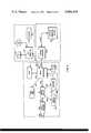
- FIG. 1is a schematic block diagram of a remote condition reporting system according to the present invention
- FIG. 2is a block diagram of a central data receiving station for use with a plurality of remote reporting systems according to the present invention
- FIG. 3is a block diagram of a more extensive central data receiving station for use with the present invention.
- FIG. 4which includes parts A through I, is a flow diagram illustrating the operation of the present invention.
- FIG. 1there is shown a block diagram of the remote data handling and reporting system according to the present invention.
- the system of FIG. 1is intended for installation at a home or other utility user, for connection to the utility meters at the home, together with optional connections for sensors for emergency conditions.
- the systemcommunicates via standard telephone lines to central offices for the various utilities, and also to the appropriate authorities in case of emergency.
- the system of FIG. 1is built around microprocessor or data processor 10.
- Microprocessor 10provides the memory, control and sequencing for the operation of the system. Any type of integrated circuit microprocessor can be used, such as those manufactured by Texas Instruments, AMI or others.
- the microprocessorcontains the necessary arithmetic and logic functional blocks for operating the system, as well as memory (indicated by reference number 11) for data handling and for system operation.
- Data processor 10includes two different types of memory.
- a read only memory (ROM)holds the firmware program for control and sequencing of all operations as described hereinafter.
- a random access memory (RAM)is used for storing a number of items unique to the particular home location or city. These include all phone numbers to be called, including emergency reporting, utility meter reporting and bank phone numbers. Also included in the RAM is a code number for the identification of the location of the particular home unit.
- Real time information designating the day of the month and the time of day that the particular home is to be read for metering of each of the utilities served by the systemis also loaded in the RAM.
- Each home remote unitis preferably set to call at night when there is less likelihood of interruption of normal home phone service, and the home units in a given town or district of a town are set to make their reporting calls on a staggered basis at different times of night and different days of the month so as to even out the traffic at the central office.
- the RAMcontains provisions for storing the time of day metering (peak power) data on a daily updated basis, so that separate totals for off peak period and on peak period can be maintained and reported to the electric utility company.
- FIG. 1is not necessarily exclusively directed to any one type of microprocessor, but may be adapted as may be required for different microprocessors.
- the multiplexing of inputsmay be revised as is generally known in the art to accommodate different types and numbers of inputs.
- data select or data strobe linesmay be multiplexed as is generally known in the art in order to provide the required number of data select functions in a given application, depending upon the number of available data select lines on a given processor.
- FIG. 1as illustrative of a number of different possible input/output connections which could be provided according to the present invention.
- data processor 10includes a four bit data input 12, and an eight bit data output 13.
- the processoralso includes a plurality of data select lines or data strobe lines numbered 21-36.
- Battery 15receives charging current from a power supply 16 which is connected to standard 60-cycle house current lines. Battery 15 provides the capability for the system to remain functional in the event of an electrical power outage. In fact, the system may easily be made operable to automatically call and report the location and time of the power outage, as explained more fully hereinafter.
- Datais fed into data processor 10 through inputs 12 from a plurality of sources, by means of a plurality of multiplexer circuits or signal gates which are controlled by the data select lines as follows.
- a latch circuit 40is provided for receiving four inputs indicated by reference number 41. These inputs may be connected to contact closure types of utility meters, for example a water meter, gas meter, an electric meter, and a test function. With a contact closure type of meter, an electrical switch closure is provided periodically according to the rate of usage of the metered quantity, but no accumulated total is maintained, at least electronically, in the meter.
- Latch 40contains four individual latch circuits which are set by occurrence of a meter closure, then remain set until read and subsequently reset or cleared by a pulse on data select line 30.
- Data from latch 40is fed via data trunk 42 to inputs of a multiplex circuit 43. It will be understood that data trunk 42 actually contains four separate data lines which are shown as a single data trunk in the drawing of FIG. 1, for purposes of clarity.
- An additional set of four inputs, indicated by reference number 44are fed into another multiplexing circuit 45. These four inputs are for connection to contact closure type sensors for detection of emergency conditions. For example, they can be connected to sensors for low water pressure, electrical power failure, a burglar alarm and a fire detector.
- Data select line 29 from the data processorconnects to multiplexer 45 for control of the selection of these data lines.
- Data trunk 46connects from the output of multiplexer 45 to the input of another multiplexer 47.
- this type of datais accommodated by a pair of multiplex circuits 50 and 51.
- BCD codingone BCD digit (four bits) is applied to input 52 to multiplexer 50, and another decimal digit (four more bits) is applied through input 53 to the multiplexer 50.
- additional datais applied to inputs 54 and 55 which connect to multiplexer 51.
- Data select line 28 from the processor 10connects to both multiplexers 50 and 51.
- the outputs from multiplexers 50 and 51connect by data trunks 56 and 57 respectively to inputs of another multiplexer 60, which is connected for control by data select line 27.
- the output of multiplexer 60is conveyed by data trunk 61 to the other input of multiplexer 47.
- Multiplexer 47is connected for control by data select line 26, and its output is fed over data trunk 62 to multiplexer 43.
- Multiplexer 43is connected for control by data select line 25, and the output from multiplexer 43 is connected via data trunk 63 to one input of another multiplex circuit 64, which is connected for control by data select line 22.
- a calendar clock circuit 70is provided for producing timing signals indicating time of day and day of the month for reporting purposes.
- clock 70may be connected via lead 71 to 60 cycle house current as a timing reference.
- the output of clock 70is conveyed by data trunks 72 and 73 to inputs of another multiplexer circuit 74, which is connected for control by data select line 23.
- the output of multiplex circuit 74is connected via data trunk 75 to one input of a multiplex circuit 76, which is connected for control by data select line 24.
- the other input to multiplex circuit 76is provided via data trunk 77 which is connected to the output of a keyboard logic unit 82.
- a keyboard or pad 80is optionally included as part of the system.
- a keyboardwould be an integral part of the system if the electronic fund transfer mode is included. In this case, the keyboard would also be used to load telephone numbers and other information into the RAM section of the memory. In the event a permanent keyboard is not supplied, a portable plug-in keyboard would be used to enter the required data into the memory
- Keyboard 80may be of any type, for example, a 16-key array. Contact closures within the keyboard are conveyed to logic unit 82 via data trunk 81. Logic unit 82 translates the keyboard inputs into a four bit code and applies them to data trunk 77. A digital display 83 can optionally be provided, also driven by logic unit 82, for providing a digital diplay of data entered on the keyboard.
- the output from multiplex unit 76is carried by data trunk 84 to another input to multiplex unit 64.
- Data selected by multiplex unit 64is carried by data trunk 85 to a first input of multiplex unit 86, which receives another input on data line 87.
- Multiplex unit 86operates under control of data select line 21, and the data selected thereby is passed through a buffer unit 88 if required for signal level and impedance matching, and from there via data trunk 89 to the data input 12 of data processor 10.
- Eight bit data output 13is connected via a data trunk 100 to a demultiplex circuit 101 which is connected for control by data select line 35.
- Demultiplex circuit 101selects the data path through data trunk 102 to tone generator 103, or through data trunk 104 to pulse generator circuit 105.
- the output from tone generator 103is connected by lead 106 to the switching circuit 107, and the output of pulse generator 105 is connected by lead 108 to switch circuit 107.
- Switching circuit 107operates under control of data select line 35 to alternately control connection of either the tone generator or the pulse generator through lead 111 to switch 112, and ultimately to the telephone line.
- Switch 112operates under control of data select line 34 for either sending data from the data processor and tone or pulse generators, or for receiving data from the telephone line and directing it through line 113 to tone detecting circuit 114.
- Switch 112connects via signal line 113 to the telephone line switch or lift hook control 116.
- Line switch 116is connected for control by data select line 33 which in effect controls the lift hook signal for initiating of a call, and the replace hook signal for terminating a telephone connection.
- Line switch 116connects to a data coupler 117 (if required) which connects to the telephone pair 118.
- Data control lines 31 and 32connect respectively to a pair of indicator lamps 120 and 121 which may be provided for use with the optional keyboard and fund transfer mode.
- multiplexing input circuitincluding multiplex circuits 43, 45, 47, 50, 51, 60, 64, 74, 76, and 86 can be utilized for data path selection, under control of the data processor, data select lines, so as to present to the data processor, data from the various sources.
- clock information from clock 70, keyboard entries from keyboard 80 and contact closure meter data from inputs 41, emergency condition indicating inputs from input 44, or coded meter readings from inputs 52-55can be presented to inputs 12 by controlling the state of the various multiplex circuit.
- data outputs from output 13can be used to generate tones or alternately to generate pulse trains for use in non-tone telephone exchange.
- data select line 33provides a "lift Hook" to line switch 116 to couple the system to the telephone lines.
- Switch 112is set for transmit, and demultiplexer 101 and switch 107 are setup for use in the tone generator or pulse generator as may be appropriate for a given installation.
- tone generator 103Data for successive digits of the telephone number are then presented to tone generator 103 or pulse generator 105, whichever has been selected.
- the datamay represent coded row and column data to allow tone generator 103 to produce at its output on lead 106, tones for dialing through the phone system.
- pulse generator 105it provides a pulse train output at lead 108 in response to a coded number presented at its input. In this manner, the successive digits of the telephone number are dialed out and the telephone connection is thus established.
- Switch 112then switches to connect the signal path from the telephone lines through lead 113 to tone detector 114.
- multiplex circuit 86is selected to present data from lead 87 to the data processor.
- the cooperating equipment at the central officecalled sends an acknowledgement signal, called a handshake signal, which is detected at device 114, and receipt of which is passed through lead 87 to the input of the data processor.
- the data processorproceeds to select tone generator 103, and send location identification data and meter reading or emergency message signals, etc. to the central location, in whatever data format may be required.
- the remote unitUpon completion of a transmission, the remote unit sends an end-of-message signal which is acknowledged by the central office computer.
- the microprocessor 10Upon receipt of final acknowledgement, the microprocessor 10 will cause replacement of the hook to break the telephone connection.
- each transactionis acknowledged by the central computer at the financial institution.
- a proprietary codemay be utilized to transmit information in both directions, especially in the case of data transfer in the fund transfer mode.
- the secret modewill prevent unauthorized use of the system.
- FIG. 2shows in block diagram form a typical central data receiving computer system for use in conjunction with the present invention.
- the system of FIG. 2represents a typical installation that might be used at the utility company office, or at a police, fire or other emergency facility office for receipt of reporting calls initiated by the home system of FIG. 1.
- phone lines 118 from the telephone companyare connected into a data coupler 120 and then via a line 121 to a selector switch 123.
- Selector switch 123is controlled by control signals on lead 124 from the central processor unit 125 of a computer system.
- the telephone lineis connected through lead 126 to an automatic telephone answering device 127, which couples via lead 130 to the central processor unit. This allows incoming telephone calls to be answered and the central processing unit 125 to be alerted.
- Central processor unit 125then activates tone generator 132 via lead 131 and causes selector switch 123 to connect tone generator 123 to the telephone line. The acknowledgement or handshake signal is then sent.
- Selector switch 123is then set up to connect the telephone line through lead 133 to a decoder unit 134 which receives the tone coded data from the home unit.
- the decoderconverts the incoming code to a format for presentation to the Central Processor Unit via data trunk 135.
- a teletype unit 140, a disc storage unit 141, and a printer 142can be provided as desired for storage, processing, and printout of data.
- FIG. 3An alternate central computer system is shown in FIG. 3.
- the data coupler, tone generator, selector switch automatic answering device and decoderoperate as in FIG. 2, but in conjunction with a microprocessor 145 rather than the central processor of a large computer system.
- FIG. 3The system of FIG. 3 would be used for example where a utility company already has an existing computer system 150. It is not economically efficient to tie up the existing computer in call answering and data receiving, so microprocessor 145 is provided for this function. Data can be stored within the microprocessor system and the existing computer can obtain information when required via data trunks 146 and 148 and a custom interface 147, if required.
- the microprocessor system 145 and associated componentscould also function as a stand alone unit at a police or fire department of a small city.
- the microprocessor systemcan provide essentially the same functions as the system illustrated in FIG. 2 at a lower cost. However, for more sophisticated systems, a mini computer becomes more economically feasible.
- mini computer systemincluding mini computer 151 could be provided.
- the mini computer systemcan be programed to handle payroll and accounting functions, for example, in addition to processing utility bills.
- the printer in either FIG. 2 or 3can be used to print out the location and nature of the emergency condition being reported, in conjunction with a suitable warning light or alarm device.
- steps 160 through 185may be considered a major cycle for the scanning of the various inputs to see whether action is required.
- the basic scan cyclethen branches off into a number of subroutines or calling cycles as may be appropriate.
- the fire detector contactis interrogated at step 161
- the burglar alarm contactis interrogated at step 162
- the electrical power failure contactis interrogated at step 163
- the water pressure contactis interrogated at step 164. If any of these steps results in a contact closed situation, an appropriate calling cycle is initiated at point A as will be explained hereinafter. Otherwise, the flow chart proceeds on to examine other inputs.
- each of these individual stepsinvolves strobing the appropriate data select lines which control the multiplexers, so as to present the reference number 44 inputs from FIG. 1 to the data processor. The appropriate one of these inputs is then examined.
- step 165selects the latch which receives inputs 41.
- the water meter contactis interrogated and if closed, step 166a stores the count in the memory within the data processor.
- the gas meter contactis then examined at step 167 and if closed, the count is incremented and stored at step 167a.
- the electric meter contactis then examined at step 168 and if closed, the count is incremented and stored in memory at step 168a.
- the test contactis then examined at step 169 if closed, the path branches to reset to latch at 170 and then proceed to point C.
- step 171also resets the latch and the clock is strobed at step 172. If a test is scheduled at the predetermined time from storage in memory, a branch to point C follows. If no test is scheduled the clock is strobed and step 175 checks for the beginning of a peak power period. If no peak period is beginning, the clock is strobed and step 177 compares for the predetermined time for the ending of a peak power period.
- step 177If the result of step 177 is negative, the clock is strobed and (continuing across point D) memory is consulted at step 179 to see whether an electric meter reading is scheduled. If not, the closk is strobed, and memory is consulted for a predetermined water meter reading schedule. Block 183 likewise compares for the time for a scheduled gas meter reading. If any of steps 179, 181, or 183 are positive, a branch to point E occurs. Otherwise, the keyboard is strobed at step 184 and step 185 determines whether any request for electronic fund transfer system (EFTS) is made. If negative, the system returns on the major scan cycle to the starting point at 160.
- EFTSelectronic fund transfer system
- a calling cycleis initiated.
- the phone lineis checked in step 200 to see whether it is in use. If it is in use, the line is seized from the user, assuming that the call has been placed from the home.
- the line switchis activated at step 202, and step 203 waits a predetermined time interval, for example, three seconds, to insure receipt of a dial tone.
- the fire department, police department, electric utility company or water utility companyis then dialed at step 204 through 207, according to which of steps 161 through 164 initiated the calling cycle, and the flow paths are correspondingly indicated in solid, broken, dotted, and center line, respectively.
- Step 210checks whether the line is busy, and if so a branch to the abort and retry step 211 occurs to reinitiate the calling cycle. After three re-tries, the calling cycle is aborted at step 212 and control returns to the start of the scan cycle 160.
- step 213If the line is not busy, receipt of the handshake signal is tested at step 213, after an appropriate delay. If no handshake is received, a branch to the abort step 211 occurs. Otherwise the identification code for the home unit is transmitted at step 214. Receipt of an end of message signal from the central station computer is then tested at step 215, and if not received, a branch to abort and retry 211 occurs. Otherwise, the line switch replaces the hook at step 216, and control returns to the starting point 160.
- Steps 220 through 229operate in a manner similar to steps 200 through 216 except that the call is placed to the company office and a test message is sent to the central office and acknowledged. In this manner, the home units perform a self test function and records of the tests are kept in a computer at the central company office to make sure that all home units are operating properly.
- step 175If the beginning of a peak power period was indicated in step 175, the next step would have been a branch to step 230, in case a contact closure type of electric meter is used at one of the inputs 41 in FIG. 1, or to step 231, in case an accumulating type meter were used at inputs 52 through 55 in FIG. 1. In either case, the new reading is stored in memory.
- step 177electric pulses from a contact closure type meter are stored in the normal period register by step 233. If an accumulating type meter is being used, the electric meter is strobed at step 234. The peak power usage, which is the difference between the reading at step 234 and at step 232, is then calculated at step 235. The peak amount is then added to a total or peak period usage at step 236.
- Steps 240 through 249are similar to the calling steps previously described.
- the gas, water or electric utilityis dialed at the appropriate one of steps 250, 251 or 252.
- the flow pathsare indicated in solid, broken or center lines corresponding with the paths from steps 179, 181 or 183.
- the gas meteris strobed at step 253, if from an accumulating type meter applied to inputs such as 52 through 55 in FIG. 1.
- the gas meteris strobed at step 253, if from an accumulating type meter applied to inputs such as 52 through 55 in FIG. 1.
- the accumulated pulsesare retrieved from memory and transmitted at step 254. Similar steps 255 and 256 apply in the case of a water reading.
- step 257supplies the current meter data.
- the peak power totalis transmitted at step 258, the normal period power total at step 259, and the total electric reading is transmitted at step 260.
- step 270In case of a request for electronic fund transfer service, a branch to step 270 would have resulted from step 185.
- a calling cycleis initiated for calling the bank at which the home owner is an account holder.
- Steps 270 through 277are identical to steps discussed in the previous calling cycles, except that the phone number for the bank is recalled from memory and dialed at step 273.
- the operatortransmitts account number and/or personal identification number information by means of keyboard 80. If the numbers sent are valid, the computer at the bank sends an acknowledgement signal which is tested for receipt at step 281. If no acknowledgement is received, indicating an erroneous or otherwise inoperative account number, reject display 120 of FIG. 1, is energized at step 282.
- the callis aborted, and another attempt may be made, up to a limit of three tries, or whatever other limit is set.
- the operatorcan contact the company's central office by initiating a test calling cycle previously discussed.
- the proceed display 121is energized at step 283.
- the operatorthen enters data according to the nature and amount of the particular transaction or plurality of transactions, at step 284. If there are to be more than one transactions, such as a plurality of bank transfers for payment of bills, the operator will send an end-of-group message at step 285, by depressing an appropriate function key on the keyboard.
- the proceed displayis energized at step 287, and the path branches back to step 284 so that the cycle can be repeated for another transaction. If acknowledgement is not received, such as due to faulty communications, or a transaction exceeding the account limits, no acknowledgement will be sent by the bank computer, and the reject display will be energized at step 282.
- the operatorsends an end of message signal at step 288.
- the proceed displayis energized at step 290 indicating successful completion of the transaction.
- the hookis then replaced by the line switch at step 291, the proceed display is deenergized at step 292, and control returns to the starting point at 160 for resumption of the scanning cycle.
- the present inventionthus provides automatic means for remote installation for automatically monitoring and initiating reporting calls to appropriate locations, in the case of emergency, routine utility meter reading reports, or operator initiated request for service or bank transactions.
Landscapes
- Engineering & Computer Science (AREA)
- Signal Processing (AREA)
- Physics & Mathematics (AREA)
- General Physics & Mathematics (AREA)
- Computer Networks & Wireless Communication (AREA)
- Telephonic Communication Services (AREA)
Abstract
Description
Claims (11)
Priority Applications (1)
| Application Number | Priority Date | Filing Date | Title |
|---|---|---|---|
| US05/721,319US4086434A (en) | 1976-09-07 | 1976-09-07 | Remote condition reporting system |
Applications Claiming Priority (1)
| Application Number | Priority Date | Filing Date | Title |
|---|---|---|---|
| US05/721,319US4086434A (en) | 1976-09-07 | 1976-09-07 | Remote condition reporting system |
Publications (1)
| Publication Number | Publication Date |
|---|---|
| US4086434Atrue US4086434A (en) | 1978-04-25 |
Family
ID=24897478
Family Applications (1)
| Application Number | Title | Priority Date | Filing Date |
|---|---|---|---|
| US05/721,319Expired - LifetimeUS4086434A (en) | 1976-09-07 | 1976-09-07 | Remote condition reporting system |
Country Status (1)
| Country | Link |
|---|---|
| US (1) | US4086434A (en) |
Cited By (135)
| Publication number | Priority date | Publication date | Assignee | Title |
|---|---|---|---|---|
| US4137429A (en)* | 1977-06-29 | 1979-01-30 | Napco Security Systems, Inc. | Digital dialers for use in the security field |
| EP0005842A1 (en)* | 1978-06-01 | 1979-12-12 | Universal Industrial Control Devices Ltd. | High speed central office scanner |
| FR2431803A1 (en)* | 1978-07-20 | 1980-02-15 | Secom Sa | Programmed telephone message transmission system - has transformer coils respectively coupled to relay and microprocessor having memory at read input |
| US4216461A (en)* | 1977-09-06 | 1980-08-05 | Brehm Timothy L | Code controlled microcontroller readout from coin operated machine |
| EP0013982A1 (en)* | 1979-01-26 | 1980-08-06 | Metretek Incorporated | Method and apparatus for remote sensor monitoring, metering and control |
| EP0019553A1 (en)* | 1979-05-18 | 1980-11-26 | TRAITEMENT DE L'INFORMATION TECHNIQUES NOUVELLES Société Anonyme Française | Autonomous device for the automatic calling via a switched network for a data processing system |
| US4254472A (en)* | 1978-08-14 | 1981-03-03 | The Valeron Corporation | Remote metering system |
| US4273960A (en)* | 1979-11-14 | 1981-06-16 | Gte Products Corporation | Apparatus for monitoring usage of a telephone |
| US4273961A (en)* | 1979-11-14 | 1981-06-16 | Gte Laboratories Incorporated | Apparatus for communicating with processing apparatus over a telephone network |
| WO1981002085A1 (en)* | 1980-01-04 | 1981-07-23 | W Asip | System for remote monitoring and data transmission over non-dedicated telephone lines |
| US4284849A (en)* | 1979-11-14 | 1981-08-18 | Gte Products Corporation | Monitoring and signalling system |
| US4287567A (en)* | 1978-06-01 | 1981-09-01 | Universal Industrial Control Devices Ltd. | High speed central office scanner |
| EP0037573A1 (en)* | 1980-04-07 | 1981-10-14 | NEWART ELECTRONIC SCIENCES, Inc. | Automatic telephonic message transmitting apparatus |
| US4308430A (en)* | 1979-11-14 | 1981-12-29 | Gte Products Corp. | Apparatus for signalling system |
| US4314103A (en)* | 1978-09-29 | 1982-02-02 | Plantronics, Inc. | Telephone answering system with simulated dial tone disconnect protection |
| EP0050451A1 (en)* | 1980-10-20 | 1982-04-28 | Minnesota Mining And Manufacturing Company | Alarm data concentration and gathering system |
| US4332980A (en)* | 1980-05-30 | 1982-06-01 | Harris Corporation | Multiple services system using telephone local loop |
| US4338493A (en)* | 1979-06-27 | 1982-07-06 | Siemens Aktiengesellschaft | Method and devices for reporting emergency calls and for initiating emergency assistance measures |
| FR2500242A1 (en)* | 1981-02-17 | 1982-08-20 | Pinet Andre | Remote communication system using telephone network - has line unit connected to telephone line and control unit and peripheral installations connectable to control terminal |
| US4360890A (en)* | 1979-11-14 | 1982-11-23 | Gte Products Corp. | Apparatus for signalling system |
| FR2516328A1 (en)* | 1981-11-06 | 1983-05-13 | Thomson Csf Mat Tel | Data collection, storage and transmission system - uses multiplexer to allow transmission via telephone line to central processor through MODEM and interface |
| US4412292A (en)* | 1981-02-17 | 1983-10-25 | The Coca-Cola Company | System for the remote monitoring of vending machines |
| US4455453A (en)* | 1979-01-26 | 1984-06-19 | Metretek, Incorporated | Apparatus and method for remote sensor monitoring, metering and control |
| FR2543302A1 (en)* | 1983-03-24 | 1984-09-28 | Electricite De France | Apparatus for metering on command and reading by telephone line |
| EP0123430A1 (en)* | 1983-03-24 | 1984-10-31 | Possum Controls Limited | Control system for apparatuses in the environment of a disabled person |
| US4549044A (en)* | 1983-10-06 | 1985-10-22 | Cermetek Microelectronics, Inc. | Remote telemetry unit |
| EP0101788A3 (en)* | 1982-06-10 | 1986-02-05 | Rockwell International Corporation | Accumulator and transponder for time related data |
| US4628313A (en)* | 1984-09-12 | 1986-12-09 | Telemeter Corporation | Apparatus and method for remotely monitoring a utility meter by use of a liquid crystal display |
| US4641127A (en)* | 1985-01-30 | 1987-02-03 | Hogan Dennis R | Security and fire protection system |
| US4654638A (en)* | 1978-09-28 | 1987-03-31 | Cadin Electronics Pty. Ltd. | Security monitoring system |
| US4672653A (en)* | 1986-01-15 | 1987-06-09 | Loveless John H | Remote security system |
| US4680704A (en)* | 1984-12-28 | 1987-07-14 | Telemeter Corporation | Optical sensor apparatus and method for remotely monitoring a utility meter or the like |
| WO1987007993A1 (en)* | 1986-06-20 | 1987-12-30 | Badger Meter, Inc. | Automatic meter reading system |
| US4728950A (en)* | 1984-04-16 | 1988-03-01 | Telemeter Corporation | Magnetic sensor apparatus for remotely monitoring a utility meter or the like |
| FR2609223A1 (en)* | 1987-11-05 | 1988-07-01 | Mecelec Sa | System for reading meters telephonically |
| EP0214915A3 (en)* | 1985-09-11 | 1988-07-20 | Alcatel N.V. | Information collecting and forwarding apparatus and method of operating such an apparatus |
| US4764952A (en)* | 1987-03-18 | 1988-08-16 | Feliu Horace G | Telecommunications device for reading power meters |
| EP0234711A3 (en)* | 1986-01-21 | 1988-12-14 | Snowflake Systems Limited | Information transmission/processing |
| EP0305630A2 (en) | 1982-06-10 | 1989-03-08 | M & FC HOLDING COMPANY, INC. | Data accumulator and transponder |
| EP0317082A1 (en)* | 1987-11-20 | 1989-05-24 | General Instrument Corporation | Spontaneous reporting of remotely generated data |
| US4845486A (en)* | 1986-09-12 | 1989-07-04 | Robert Scully | Residential fuel-oil level reporting and alarm system |
| US4845484A (en)* | 1987-10-09 | 1989-07-04 | Bellatrix Systems, Inc. | Retrofit, newspaper tracking audit system for newspaper rack machines |
| US4893332A (en)* | 1986-05-12 | 1990-01-09 | Aquatrol Corporation | Low-powered remote sensor |
| WO1990001841A1 (en)* | 1988-08-12 | 1990-02-22 | The Inteleplex Corporation | Transient signal eliminating circuit for telecommunications applications |
| EP0390666A1 (en)* | 1989-03-28 | 1990-10-03 | Elf Antar France | Monitoring system for industrial installations |
| FR2647236A1 (en)* | 1989-05-16 | 1990-11-23 | Huan Armand | Installation for management and monitoring of one or more production sites |
| US4979094A (en)* | 1987-04-07 | 1990-12-18 | Possum Controls Limited | Control system |
| EP0339697A3 (en)* | 1988-03-31 | 1991-03-13 | Industria Grafica Meschi S.r.l. | Method and apparatus for teleprinting public services data at the subscriber |
| EP0429364A1 (en)* | 1989-11-21 | 1991-05-29 | Goldstar Co. Ltd. | Supervisory alarm transmission and remote alarm receipt devices |
| US5036966A (en)* | 1989-06-12 | 1991-08-06 | Kaspar Wire Works, Inc. | Newspaper vending rack coin box incorporating a retrofit electronic coin mechanism |
| US5081680A (en)* | 1987-11-20 | 1992-01-14 | General Instrument Corporation | Initial reporting of remotely generated data |
| US5184179A (en)* | 1988-05-17 | 1993-02-02 | Monitel Products Corp. | Photocopy monitoring system and method for monitoring copiers |
| US5216461A (en)* | 1990-07-31 | 1993-06-01 | Minolta Camera Kabushiki Kaisha | Control system for copying machine with improved communication function to centralized control unit |
| US5224157A (en)* | 1989-05-22 | 1993-06-29 | Minolta Camera Kabushiki Kaisha | Management system for managing maintenance information of image forming apparatus |
| EP0566242A1 (en)* | 1992-03-20 | 1993-10-20 | AT&T Corp. | Remotely initiated telemetry calling system |
| US5309506A (en)* | 1991-10-25 | 1994-05-03 | Forerunner Corporation | Personal services telephone handset and system |
| US5327493A (en)* | 1991-05-02 | 1994-07-05 | Active Voice, Inc. | Device for detecting tones on telephone lines |
| US5345225A (en)* | 1992-10-30 | 1994-09-06 | Scientific-Atlanta, Inc. | Tamper detection system for load management device |
| US5381462A (en)* | 1992-05-29 | 1995-01-10 | Datran Systems Corporation | Utility monitor communications systems |
| US5434911A (en)* | 1993-06-04 | 1995-07-18 | M & Fc Holding Company, Inc. | Call in-bound remote reading and data collection system |
| US5452344A (en)* | 1992-05-29 | 1995-09-19 | Datran Systems Corporation | Communication over power lines |
| US5454031A (en)* | 1993-06-04 | 1995-09-26 | M & Fc Holding Company, Inc. | Dial inbound meter interface unit which derives its power from a telephone line |
| US5469365A (en)* | 1993-01-25 | 1995-11-21 | Customs Ideas | Power monitor unit |
| US5491535A (en)* | 1990-04-10 | 1996-02-13 | Minolta Camera Kabushiki Kaisha | Control appartus of copying machine with improved communication function for centralized control |
| US5576700A (en)* | 1992-08-26 | 1996-11-19 | Scientific-Atlanta | Apparatus and method for controlling an electrical load and monitoring control operations and the electrical load |
| GB2300992A (en)* | 1995-05-18 | 1996-11-20 | Scantronic Ltd | Monitoring the integrity of alarm systems |
| US5590179A (en)* | 1993-02-12 | 1996-12-31 | Ekstrom Industries, Inc. | Remote automatic meter reading apparatus |
| EP0751446A3 (en)* | 1996-09-28 | 1997-05-07 | Maag Pump Systems Ag | Method and device for monitoring system units |
| US5638427A (en)* | 1994-07-01 | 1997-06-10 | Xerox Corporation | Operator-controlled interactive communication device |
| US5636653A (en)* | 1995-12-01 | 1997-06-10 | Perception Incorporated | Fluid metering apparatus and method |
| US5673190A (en)* | 1995-03-22 | 1997-09-30 | Atrix International, Inc. | Multipurpose remote office machine management system |
| US5737400A (en)* | 1996-02-27 | 1998-04-07 | U-Tel Incorporated | Telecommunications system for accessing subscriber premises equipment using ring suppression |
| US5790653A (en)* | 1995-01-06 | 1998-08-04 | Voicewaves, Inc. | Line-powered detection of call progress tones |
| US5805458A (en)* | 1993-08-11 | 1998-09-08 | First Pacific Networks | System for utility demand monitoring and control |
| US5887243A (en) | 1981-11-03 | 1999-03-23 | Personalized Media Communications, L.L.C. | Signal processing apparatus and methods |
| US5902927A (en)* | 1995-12-01 | 1999-05-11 | Perception Incorporated | Fluid metering apparatus and method |
| US5994892A (en)* | 1996-07-31 | 1999-11-30 | Sacramento Municipal Utility District | Integrated circuit design automatic utility meter: apparatus & method |
| US6076542A (en)* | 1995-12-01 | 2000-06-20 | Perception Incorporated | Fluid metering method |
| US6118373A (en)* | 1998-12-22 | 2000-09-12 | Mandry; Karl F. | Method of remotely detecting an ambient condition |
| US6219409B1 (en) | 1998-02-27 | 2001-04-17 | Sharegate, Inc. | Premises gateway and premises network interfaces for accessing subscriber premises equipment and communication networks using ring suppression |
| US6266396B1 (en) | 1998-12-11 | 2001-07-24 | Everitt O. Johnson | Digital control of a security system |
| US6307469B1 (en)* | 1998-12-22 | 2001-10-23 | Karl F. Mandry | Remote detection device |
| US6333975B1 (en) | 1998-03-03 | 2001-12-25 | Itron, Inc. | Method and system for reading intelligent utility meters |
| US6404874B1 (en) | 1997-03-27 | 2002-06-11 | Cisco Technology, Inc. | Telecommute server |
| US20020156704A1 (en)* | 2001-03-26 | 2002-10-24 | Kolls H. Brock | Method of constructing a digital content play list for transmission and presentation on a public access electronic terminal |
| US6519552B1 (en) | 1999-09-15 | 2003-02-11 | Xerox Corporation | Systems and methods for a hybrid diagnostic approach of real time diagnosis of electronic systems |
| US6522430B1 (en) | 1999-11-29 | 2003-02-18 | Xerox Corporation | Quantification of motion quality effect on image quality |
| US6529616B1 (en) | 1999-11-29 | 2003-03-04 | Xerox Corporation | Technique for accurate color-color registration measurements |
| US20030069648A1 (en)* | 2001-09-10 | 2003-04-10 | Barry Douglas | System and method for monitoring and managing equipment |
| US6571000B1 (en) | 1999-11-29 | 2003-05-27 | Xerox Corporation | Image processing algorithm for characterization of uniformity of printed images |
| US6597473B1 (en)* | 1999-11-29 | 2003-07-22 | Xerox Corporation | Method to obtain consistent image quality measurements from different image input devices |
| US6601037B1 (en) | 1998-07-20 | 2003-07-29 | Usa Technologies, Inc. | System and method of processing credit card, e-commerce, and e-business transactions without the merchant incurring transaction processing fees or charges worldwide |
| US6604085B1 (en) | 1998-07-20 | 2003-08-05 | Usa Technologies, Inc. | Universal interactive advertising and payment system network for public access electronic commerce and business related products and services |
| US6604086B1 (en) | 1998-07-20 | 2003-08-05 | Usa Technologies, Inc. | Electronic commerce terminal connected to a vending machine operable as a telephone |
| US6604087B1 (en) | 1998-07-20 | 2003-08-05 | Usa Technologies, Inc. | Vending access to the internet, business application software, e-commerce, and e-business in a hotel room |
| US6606605B1 (en) | 1998-07-20 | 2003-08-12 | Usa Technologies, Inc. | Method to obtain customer specific data for public access electronic commerce services |
| US6606395B1 (en) | 1999-11-29 | 2003-08-12 | Xerox Corporation | Method to allow automated image quality analysis of arbitrary test patterns |
| US6609103B1 (en) | 1998-07-20 | 2003-08-19 | Usa Technologies, Inc. | Electronic commerce terminal for facilitating incentive-based purchasing on transportation vehicles |
| US6608932B1 (en) | 1999-11-29 | 2003-08-19 | Xerox Corporation | Outline font for analytical assessment of printed text quality |
| US6611810B1 (en) | 1998-07-20 | 2003-08-26 | Usa Technologies, Inc. | Store display window connected to an electronic commerce terminal |
| US6629080B1 (en) | 1998-07-20 | 2003-09-30 | Usa Technologies, Inc. | Transaction processing method of fulfilling an electronic commerce transaction by an electronic commerce terminal system |
| US6643623B1 (en) | 1998-07-20 | 2003-11-04 | Usa Technologies, Inc. | Method of transacting an electronic mail, an electronic commerce, and an electronic business transaction by an electronic commerce terminal using a gas pump |
| US20030208339A1 (en)* | 2002-05-02 | 2003-11-06 | Chaos Co., Ltd. | Remote reading method of gauge data |
| US6665425B1 (en) | 1999-12-16 | 2003-12-16 | Xerox Corporation | Systems and methods for automated image quality based diagnostics and remediation of document processing systems |
| US6684197B1 (en) | 1998-07-20 | 2004-01-27 | Usa Technologies, Inc. | Method for revaluing a private label card using an electronic commerce terminal |
| US20040064351A1 (en)* | 1999-11-22 | 2004-04-01 | Mikurak Michael G. | Increased visibility during order management in a network-based supply chain environment |
| US6753987B1 (en) | 2000-02-25 | 2004-06-22 | Xerox Corporation | Systems and methods to determine a contrast and a brightness adjusted system tone reproduction curve |
| US6763336B1 (en) | 1998-07-20 | 2004-07-13 | Usa Technologies, Inc. | Method of transacting an electronic mail, an electronic commerce, and an electronic business transaction by an electronic commerce terminal using a wirelessly networked plurality of portable digital devices |
| US20040174969A1 (en)* | 2003-03-06 | 2004-09-09 | International Business Machines Corporation | Device for responding to state request on an open phone line |
| US6807532B1 (en) | 1998-07-20 | 2004-10-19 | Usa Technologies, Inc. | Method of soliciting a user to input survey data at an electronic commerce terminal |
| US6842266B1 (en) | 2000-02-25 | 2005-01-11 | Xerox Corporation | Systems and methods that determine an image processing system tone reproduction curve |
| US6892317B1 (en) | 1999-12-16 | 2005-05-10 | Xerox Corporation | Systems and methods for failure prediction, diagnosis and remediation using data acquisition and feedback for a distributed electronic system |
| US6904385B1 (en)* | 1998-05-29 | 2005-06-07 | Powerweb, Inc. | Multi-utility energy control system with internet energy platform having diverse energy-related engines |
| US6912071B1 (en)* | 1999-11-29 | 2005-06-28 | Xerox Corporation | Virtual tech rep by remote image quality analysis |
| US6940956B1 (en) | 2000-05-04 | 2005-09-06 | Amron Technologies, Inc. | Electric outlet based power status notification device, system, and method |
| US20050195078A1 (en)* | 2004-03-02 | 2005-09-08 | Vann Basinger | Method and apparatus for all-purpose, automatic remote utility meter reading, utility shut off, and hazard warning and correction |
| US7117239B1 (en) | 2000-07-28 | 2006-10-03 | Axeda Corporation | Reporting the state of an apparatus to a remote computer |
| US7149792B1 (en) | 2000-11-20 | 2006-12-12 | Axeda Corporation | Device registration mechanism |
| US7185014B1 (en) | 2000-09-22 | 2007-02-27 | Axeda Corporation | Retrieving data from a server |
| US7716077B1 (en) | 1999-11-22 | 2010-05-11 | Accenture Global Services Gmbh | Scheduling and planning maintenance and service in a network-based supply chain environment |
| US7769344B1 (en) | 1981-11-03 | 2010-08-03 | Personalized Media Communications, Llc | Signal processing apparatus and methods |
| US20100250118A1 (en)* | 2009-03-24 | 2010-09-30 | International Business Machines Corporation | Portable navigation device point of interest selection based on store open probability |
| US20100305891A1 (en)* | 2003-09-08 | 2010-12-02 | Smartsynch, Inc. | Methods for reading data in a utility meter |
| US7957991B2 (en) | 1999-11-22 | 2011-06-07 | Accenture Global Services Limited | Technology sharing during demand and supply planning in a network-based supply chain environment |
| US7966418B2 (en) | 2003-02-21 | 2011-06-21 | Axeda Corporation | Establishing a virtual tunnel between two computer programs |
| EP2348471A1 (en) | 2000-04-17 | 2011-07-27 | Accenture Global Services GmbH | Method for a contract manufacturing framework |
| US8032409B1 (en) | 1999-11-22 | 2011-10-04 | Accenture Global Services Limited | Enhanced visibility during installation management in a network-based supply chain environment |
| US8060886B2 (en) | 2002-04-17 | 2011-11-15 | Axeda Corporation | XML scripting of SOAP commands |
| US8065397B2 (en) | 2006-12-26 | 2011-11-22 | Axeda Acquisition Corporation | Managing configurations of distributed devices |
| US8108543B2 (en) | 2000-09-22 | 2012-01-31 | Axeda Corporation | Retrieving data from a server |
| US8370479B2 (en) | 2006-10-03 | 2013-02-05 | Axeda Acquisition Corporation | System and method for dynamically grouping devices based on present device conditions |
| US8406119B2 (en) | 2001-12-20 | 2013-03-26 | Axeda Acquisition Corporation | Adaptive device-initiated polling |
| WO2013042130A1 (en) | 2011-09-19 | 2013-03-28 | Pathi Viraj Kumar | A smart hub and the method of operating thereof |
| US8478861B2 (en) | 2007-07-06 | 2013-07-02 | Axeda Acquisition Corp. | Managing distributed devices with limited connectivity |
| USRE47642E1 (en) | 1981-11-03 | 2019-10-08 | Personalized Media Communications LLC | Signal processing apparatus and methods |
Citations (6)
| Publication number | Priority date | Publication date | Assignee | Title |
|---|---|---|---|---|
| US3390234A (en)* | 1967-02-27 | 1968-06-25 | Glidden Electric Corp | Combination telephone fire alarm and meter reading system |
| US3553376A (en)* | 1968-08-28 | 1971-01-05 | Peter Bogaart | Remote meter reading method and apparatus |
| US3588357A (en)* | 1969-06-19 | 1971-06-28 | Itt | Automatic remote meter reading over telephone line |
| US3842208A (en)* | 1970-01-26 | 1974-10-15 | Paraskevakos Elect & Comm | Sensor monitoring device |
| US3883695A (en)* | 1973-05-14 | 1975-05-13 | Vertex Science Ind Inc | Alarm reporting system for transmitting digital alarm signals via a telephone line |
| US3922490A (en)* | 1973-06-18 | 1975-11-25 | Charles D Pettis | Alarm and utility meter reading system employing telephone lines |
- 1976
- 1976-09-07USUS05/721,319patent/US4086434A/ennot_activeExpired - Lifetime
Patent Citations (6)
| Publication number | Priority date | Publication date | Assignee | Title |
|---|---|---|---|---|
| US3390234A (en)* | 1967-02-27 | 1968-06-25 | Glidden Electric Corp | Combination telephone fire alarm and meter reading system |
| US3553376A (en)* | 1968-08-28 | 1971-01-05 | Peter Bogaart | Remote meter reading method and apparatus |
| US3588357A (en)* | 1969-06-19 | 1971-06-28 | Itt | Automatic remote meter reading over telephone line |
| US3842208A (en)* | 1970-01-26 | 1974-10-15 | Paraskevakos Elect & Comm | Sensor monitoring device |
| US3883695A (en)* | 1973-05-14 | 1975-05-13 | Vertex Science Ind Inc | Alarm reporting system for transmitting digital alarm signals via a telephone line |
| US3922490A (en)* | 1973-06-18 | 1975-11-25 | Charles D Pettis | Alarm and utility meter reading system employing telephone lines |
Cited By (282)
| Publication number | Priority date | Publication date | Assignee | Title |
|---|---|---|---|---|
| US4137429A (en)* | 1977-06-29 | 1979-01-30 | Napco Security Systems, Inc. | Digital dialers for use in the security field |
| US4216461A (en)* | 1977-09-06 | 1980-08-05 | Brehm Timothy L | Code controlled microcontroller readout from coin operated machine |
| EP0005842A1 (en)* | 1978-06-01 | 1979-12-12 | Universal Industrial Control Devices Ltd. | High speed central office scanner |
| US4287567A (en)* | 1978-06-01 | 1981-09-01 | Universal Industrial Control Devices Ltd. | High speed central office scanner |
| FR2431803A1 (en)* | 1978-07-20 | 1980-02-15 | Secom Sa | Programmed telephone message transmission system - has transformer coils respectively coupled to relay and microprocessor having memory at read input |
| US4254472A (en)* | 1978-08-14 | 1981-03-03 | The Valeron Corporation | Remote metering system |
| US4654638A (en)* | 1978-09-28 | 1987-03-31 | Cadin Electronics Pty. Ltd. | Security monitoring system |
| US4314103A (en)* | 1978-09-29 | 1982-02-02 | Plantronics, Inc. | Telephone answering system with simulated dial tone disconnect protection |
| EP0013982A1 (en)* | 1979-01-26 | 1980-08-06 | Metretek Incorporated | Method and apparatus for remote sensor monitoring, metering and control |
| US4241237A (en)* | 1979-01-26 | 1980-12-23 | Metretek Incorporated | Apparatus and method for remote sensor monitoring, metering and control |
| US4455453A (en)* | 1979-01-26 | 1984-06-19 | Metretek, Incorporated | Apparatus and method for remote sensor monitoring, metering and control |
| EP0019553A1 (en)* | 1979-05-18 | 1980-11-26 | TRAITEMENT DE L'INFORMATION TECHNIQUES NOUVELLES Société Anonyme Française | Autonomous device for the automatic calling via a switched network for a data processing system |
| FR2457046A1 (en)* | 1979-05-18 | 1980-12-12 | Traitement Information Tech Nl | SELF-CONTAINED AUTOMATIC CALLING NETWORK APPARATUS FOR INFORMATION PROCESSING SYSTEM |
| US4338493A (en)* | 1979-06-27 | 1982-07-06 | Siemens Aktiengesellschaft | Method and devices for reporting emergency calls and for initiating emergency assistance measures |
| US4360890A (en)* | 1979-11-14 | 1982-11-23 | Gte Products Corp. | Apparatus for signalling system |
| US4273960A (en)* | 1979-11-14 | 1981-06-16 | Gte Products Corporation | Apparatus for monitoring usage of a telephone |
| US4308430A (en)* | 1979-11-14 | 1981-12-29 | Gte Products Corp. | Apparatus for signalling system |
| US4284849A (en)* | 1979-11-14 | 1981-08-18 | Gte Products Corporation | Monitoring and signalling system |
| US4273961A (en)* | 1979-11-14 | 1981-06-16 | Gte Laboratories Incorporated | Apparatus for communicating with processing apparatus over a telephone network |
| WO1981002085A1 (en)* | 1980-01-04 | 1981-07-23 | W Asip | System for remote monitoring and data transmission over non-dedicated telephone lines |
| US4361851A (en)* | 1980-01-04 | 1982-11-30 | Asip William F | System for remote monitoring and data transmission over non-dedicated telephone lines |
| US4371751A (en)* | 1980-04-07 | 1983-02-01 | Newart Electronic Sciences, Inc. | Automatic telephonic user emergency message transmitting apparatus |
| EP0037573A1 (en)* | 1980-04-07 | 1981-10-14 | NEWART ELECTRONIC SCIENCES, Inc. | Automatic telephonic message transmitting apparatus |
| US4332980A (en)* | 1980-05-30 | 1982-06-01 | Harris Corporation | Multiple services system using telephone local loop |
| US4447872A (en)* | 1980-10-20 | 1984-05-08 | Minnesota Mining And Manufacturing Company | Alarm data concentration and gathering system |
| EP0050451A1 (en)* | 1980-10-20 | 1982-04-28 | Minnesota Mining And Manufacturing Company | Alarm data concentration and gathering system |
| US4412292A (en)* | 1981-02-17 | 1983-10-25 | The Coca-Cola Company | System for the remote monitoring of vending machines |
| FR2500242A1 (en)* | 1981-02-17 | 1982-08-20 | Pinet Andre | Remote communication system using telephone network - has line unit connected to telephone line and control unit and peripheral installations connectable to control terminal |
| US9043859B1 (en) | 1981-11-02 | 2015-05-26 | Personalized Media Communications, Llc | Signal processing apparatus and methods |
| US7889865B1 (en) | 1981-11-03 | 2011-02-15 | Personalized Media Communications, L.L.C. | Signal processing apparatus and methods |
| US7856650B1 (en) | 1981-11-03 | 2010-12-21 | Personalized Media Communications, Llc | Signal processing apparatus and methods |
| US7849479B1 (en) | 1981-11-03 | 2010-12-07 | Personalized Media Communications, Llc | Signal processing apparatus and methods |
| US7844995B1 (en) | 1981-11-03 | 2010-11-30 | Personalized Media Communications, Llc | Signal processing apparatus and methods |
| US7840976B1 (en) | 1981-11-03 | 2010-11-23 | Personalized Media Communications, Llc | Signal processing apparatus and methods |
| US7836480B1 (en) | 1981-11-03 | 2010-11-16 | Personalized Media Communications, Llc | Signal processing apparatus and methods |
| US7830925B1 (en) | 1981-11-03 | 2010-11-09 | Personalized Media Communications, Llc | Signal processing apparatus and methods |
| US7831204B1 (en) | 1981-11-03 | 2010-11-09 | Personalized Media Communications, Llc | Signal processing apparatus and methods |
| US7827586B1 (en) | 1981-11-03 | 2010-11-02 | Personalized Media Communications, Llc | Signal processing apparatus and methods |
| US7827587B1 (en) | 1981-11-03 | 2010-11-02 | Personalized Media Communications, Llc | Signal processing apparatus and methods |
| US7823175B1 (en) | 1981-11-03 | 2010-10-26 | Personalized Media Communications LLC | Signal processing apparatus and methods |
| US7818761B1 (en) | 1981-11-03 | 2010-10-19 | Personalized Media Communications, Llc | Signal processing apparatus and methods |
| US7817208B1 (en) | 1981-11-03 | 2010-10-19 | Personalized Media Communications, Llc | Signal processing apparatus and methods |
| US7818776B1 (en) | 1981-11-03 | 2010-10-19 | Personalized Media Communications, Llc | Signal processing apparatus and methods |
| US7818778B1 (en) | 1981-11-03 | 2010-10-19 | Personalized Media Communications, Llc | Signal processing apparatus and methods |
| US7818777B1 (en) | 1981-11-03 | 2010-10-19 | Personalized Media Communications, Llc | Signal processing apparatus and methods |
| US7814526B1 (en) | 1981-11-03 | 2010-10-12 | Personalized Media Communications, Llc | Signal processing apparatus and methods |
| US7810115B1 (en) | 1981-11-03 | 2010-10-05 | Personalized Media Communications, Llc | Signal processing apparatus and methods |
| US7849480B1 (en) | 1981-11-03 | 2010-12-07 | Personalized Media Communications LLC | Signal processing apparatus and methods |
| US7856649B1 (en) | 1981-11-03 | 2010-12-21 | Personalized Media Communications, Llc | Signal processing apparatus and methods |
| US7805749B1 (en) | 1981-11-03 | 2010-09-28 | Personalized Media Communications, Llc | Signal processing apparatus and methods |
| US7805748B1 (en) | 1981-11-03 | 2010-09-28 | Personalized Media Communications, Llc | Signal processing apparatus and methods |
| US7805738B1 (en) | 1981-11-03 | 2010-09-28 | Personalized Media Communications, Llc | Signal processing apparatus and methods |
| US7801304B1 (en) | 1981-11-03 | 2010-09-21 | Personalized Media Communications, Llc | Signal processing apparatus and methods |
| US7797717B1 (en) | 1981-11-03 | 2010-09-14 | Personalized Media Communications, Llc | Signal processing apparatus and methods |
| US7793332B1 (en) | 1981-11-03 | 2010-09-07 | Personalized Media Communications, Llc | Signal processing apparatus and methods |
| US7783252B1 (en) | 1981-11-03 | 2010-08-24 | Personalized Media Communications, Llc | Signal processing apparatus and methods |
| US7784082B1 (en) | 1981-11-03 | 2010-08-24 | Personalized Media Communications, Llc | Signal processing apparatus and methods |
| US7774809B1 (en) | 1981-11-03 | 2010-08-10 | Personalized Media Communications, Llc | Signal processing apparatus and method |
| US7769170B1 (en) | 1981-11-03 | 2010-08-03 | Personalized Media Communications, Llc | Signal processing apparatus and methods |
| US7769344B1 (en) | 1981-11-03 | 2010-08-03 | Personalized Media Communications, Llc | Signal processing apparatus and methods |
| US7764685B1 (en) | 1981-11-03 | 2010-07-27 | Personalized Media Communications, L.L.C. | Signal processing apparatus and methods |
| US7761890B1 (en) | 1981-11-03 | 2010-07-20 | Personalized Media Communications, Llc | Signal processing apparatus and methods |
| US7752650B1 (en) | 1981-11-03 | 2010-07-06 | Personalized Media Communications, Llc | Signal processing apparatus and methods |
| US7752649B1 (en) | 1981-11-03 | 2010-07-06 | Personalized Media Communications, Llc | Signal processing apparatus and methods |
| US7747217B1 (en) | 1981-11-03 | 2010-06-29 | Personalized Media Communications, Llc | Signal processing apparatus and methods |
| US7734251B1 (en) | 1981-11-03 | 2010-06-08 | Personalized Media Communications, Llc | Signal processing apparatus and methods |
| US7861263B1 (en) | 1981-11-03 | 2010-12-28 | Personalized Media Communications, Llc | Signal processing apparatus and methods |
| USRE48682E1 (en) | 1981-11-03 | 2021-08-10 | Personalized Media Communications LLC | Providing subscriber specific content in a network |
| US7861278B1 (en) | 1981-11-03 | 2010-12-28 | Personalized Media Communications, Llc | Signal processing apparatus and methods |
| USRE48633E1 (en) | 1981-11-03 | 2021-07-06 | Personalized Media Communications LLC | Reprogramming of a programmable device of a specific version |
| US7860249B1 (en) | 1981-11-03 | 2010-12-28 | Personalized Media Communications LLC | Signal processing apparatus and methods |
| US7860131B1 (en) | 1981-11-03 | 2010-12-28 | Personalized Media Communications, Llc | Signal processing apparatus and methods |
| US7865920B1 (en) | 1981-11-03 | 2011-01-04 | Personalized Media Communications LLC | Signal processing apparatus and methods |
| USRE48565E1 (en) | 1981-11-03 | 2021-05-18 | Personalized Media Communications LLC | Providing a subscriber specific solution in a computer network |
| USRE48484E1 (en) | 1981-11-03 | 2021-03-23 | Personalized Media Communications, Llc | Signal processing apparatus and methods |
| US10715835B1 (en) | 1981-11-03 | 2020-07-14 | John Christopher Harvey | Signal processing apparatus and methods |
| USRE47968E1 (en) | 1981-11-03 | 2020-04-28 | Personalized Media Communications LLC | Signal processing apparatus and methods |
| US10616638B1 (en) | 1981-11-03 | 2020-04-07 | Personalized Media Communications LLC | Signal processing apparatus and methods |
| US10609425B1 (en) | 1981-11-03 | 2020-03-31 | Personalized Media Communications, L.L.C. | Signal processing apparatus and methods |
| USRE47867E1 (en) | 1981-11-03 | 2020-02-18 | Personalized Media Communications LLC | Signal processing apparatus and methods |
| US10523350B1 (en) | 1981-11-03 | 2019-12-31 | Personalized Media Communications LLC | Signal processing apparatus and methods |
| USRE47642E1 (en) | 1981-11-03 | 2019-10-08 | Personalized Media Communications LLC | Signal processing apparatus and methods |
| US5887243A (en) | 1981-11-03 | 1999-03-23 | Personalized Media Communications, L.L.C. | Signal processing apparatus and methods |
| US10334292B1 (en) | 1981-11-03 | 2019-06-25 | Personalized Media Communications LLC | Signal processing apparatus and methods |
| US9674560B1 (en) | 1981-11-03 | 2017-06-06 | Personalized Media Communications LLC | Signal processing apparatus and methods |
| US9294205B1 (en) | 1981-11-03 | 2016-03-22 | Personalized Media Communications LLC | Signal processing apparatus and methods |
| US9210370B1 (en) | 1981-11-03 | 2015-12-08 | Personalized Media Communications LLC | Signal processing apparatus and methods |
| US7864248B1 (en) | 1981-11-03 | 2011-01-04 | Personalized Media Communications, Llc | Signal processing apparatus and methods |
| US9038124B1 (en) | 1981-11-03 | 2015-05-19 | Personalized Media Communications, Llc | Signal processing apparatus and methods |
| US8973034B1 (en) | 1981-11-03 | 2015-03-03 | Personalized Media Communications LLC | Signal processing apparatus and methods |
| US8914825B1 (en) | 1981-11-03 | 2014-12-16 | Personalized Media Communications LLC | Signal processing apparatus and methods |
| US8893177B1 (en) | 1981-11-03 | 2014-11-18 | {Personalized Media Communications, LLC | Signal processing apparatus and methods |
| US8869228B1 (en) | 1981-11-03 | 2014-10-21 | Personalized Media Communications, Llc | Signal processing apparatus and methods |
| US8869229B1 (en) | 1981-11-03 | 2014-10-21 | Personalized Media Communications, Llc | Signal processing apparatus and methods |
| US8843988B1 (en) | 1981-11-03 | 2014-09-23 | Personalized Media Communications, Llc | Signal processing apparatus and methods |
| US8839293B1 (en) | 1981-11-03 | 2014-09-16 | Personalized Media Communications, Llc | Signal processing apparatus and methods |
| US8804727B1 (en) | 1981-11-03 | 2014-08-12 | Personalized Media Communications, Llc | Signal processing apparatus and methods |
| US8752088B1 (en) | 1981-11-03 | 2014-06-10 | Personalized Media Communications LLC | Signal processing apparatus and methods |
| US8739241B1 (en) | 1981-11-03 | 2014-05-27 | Personalized Media Communications LLC | Signal processing apparatus and methods |
| US8713624B1 (en) | 1981-11-03 | 2014-04-29 | Personalized Media Communications LLC | Signal processing apparatus and methods |
| US8711885B1 (en) | 1981-11-03 | 2014-04-29 | Personalized Media Communications LLC | Signal processing apparatus and methods |
| US8683539B1 (en) | 1981-11-03 | 2014-03-25 | Personalized Media Communications, Llc | Signal processing apparatus and methods |
| US8675775B1 (en) | 1981-11-03 | 2014-03-18 | Personalized Media Communications, Llc | Signal processing apparatus and methods |
| US8646001B1 (en) | 1981-11-03 | 2014-02-04 | Personalized Media Communications, Llc | Signal processing apparatus and methods |
| US8640184B1 (en) | 1981-11-03 | 2014-01-28 | Personalized Media Communications, Llc | Signal processing apparatus and methods |
| US8635644B1 (en) | 1981-11-03 | 2014-01-21 | Personalized Media Communications LLC | Signal processing apparatus and methods |
| US8621547B1 (en) | 1981-11-03 | 2013-12-31 | Personalized Media Communications, Llc | Signal processing apparatus and methods |
| US8613034B1 (en) | 1981-11-03 | 2013-12-17 | Personalized Media Communications, Llc | Signal processing apparatus and methods |
| US8607296B1 (en) | 1981-11-03 | 2013-12-10 | Personalized Media Communications LLC | Signal processing apparatus and methods |
| US8601528B1 (en) | 1981-11-03 | 2013-12-03 | Personalized Media Communications, L.L.C. | Signal processing apparatus and methods |
| US8587720B1 (en) | 1981-11-03 | 2013-11-19 | Personalized Media Communications LLC | Signal processing apparatus and methods |
| US8584162B1 (en) | 1981-11-03 | 2013-11-12 | Personalized Media Communications LLC | Signal processing apparatus and methods |
| US8572671B1 (en) | 1981-11-03 | 2013-10-29 | Personalized Media Communications LLC | Signal processing apparatus and methods |
| US8566868B1 (en) | 1981-11-03 | 2013-10-22 | Personalized Media Communications, L.L.C. | Signal processing apparatus and methods |
| US8559635B1 (en) | 1981-11-03 | 2013-10-15 | Personalized Media Communications, L.L.C. | Signal processing apparatus and methods |
| US8558950B1 (en) | 1981-11-03 | 2013-10-15 | Personalized Media Communications LLC | Signal processing apparatus and methods |
| US8555310B1 (en) | 1981-11-03 | 2013-10-08 | Personalized Media Communications, Llc | Signal processing apparatus and methods |
| US8395707B1 (en) | 1981-11-03 | 2013-03-12 | Personalized Media Communications LLC | Signal processing apparatus and methods |
| US8191091B1 (en) | 1981-11-03 | 2012-05-29 | Personalized Media Communications, Llc | Signal processing apparatus and methods |
| US8112782B1 (en) | 1981-11-03 | 2012-02-07 | Personalized Media Communications, Llc | Signal processing apparatus and methods |
| US8060903B1 (en) | 1981-11-03 | 2011-11-15 | Personalized Media PMC Communications, L.L.C. | Signal processing apparatus and methods |
| US8046791B1 (en) | 1981-11-03 | 2011-10-25 | Personalized Media Communications, Llc | Signal processing apparatus and methods |
| US7992169B1 (en) | 1981-11-03 | 2011-08-02 | Personalized Media Communications LLC | Signal processing apparatus and methods |
| US7864956B1 (en) | 1981-11-03 | 2011-01-04 | Personalized Media Communications, Llc | Signal processing apparatus and methods |
| US7870581B1 (en) | 1981-11-03 | 2011-01-11 | Personalized Media Communications, Llc | Signal processing apparatus and methods |
| US7953223B1 (en) | 1981-11-03 | 2011-05-31 | Personalized Media Communications, L.L.C. | Signal processing apparatus and methods |
| US7940931B1 (en) | 1981-11-03 | 2011-05-10 | Personalized Media Communications LLC | Signal processing apparatus and methods |
| US7926084B1 (en) | 1981-11-03 | 2011-04-12 | Personalized Media Communications LLC | Signal processing apparatus and methods |
| US7908638B1 (en) | 1981-11-03 | 2011-03-15 | Personalized Media Communications LLC | Signal processing apparatus and methods |
| US7849493B1 (en) | 1981-11-03 | 2010-12-07 | Personalized Media Communications, Llc | Signal processing apparatus and methods |
| FR2516328A1 (en)* | 1981-11-06 | 1983-05-13 | Thomson Csf Mat Tel | Data collection, storage and transmission system - uses multiplexer to allow transmission via telephone line to central processor through MODEM and interface |
| EP0101788A3 (en)* | 1982-06-10 | 1986-02-05 | Rockwell International Corporation | Accumulator and transponder for time related data |
| EP0305630A2 (en) | 1982-06-10 | 1989-03-08 | M & FC HOLDING COMPANY, INC. | Data accumulator and transponder |
| FR2543302A1 (en)* | 1983-03-24 | 1984-09-28 | Electricite De France | Apparatus for metering on command and reading by telephone line |
| EP0123430A1 (en)* | 1983-03-24 | 1984-10-31 | Possum Controls Limited | Control system for apparatuses in the environment of a disabled person |
| US4549044A (en)* | 1983-10-06 | 1985-10-22 | Cermetek Microelectronics, Inc. | Remote telemetry unit |
| US4728950A (en)* | 1984-04-16 | 1988-03-01 | Telemeter Corporation | Magnetic sensor apparatus for remotely monitoring a utility meter or the like |
| US4628313A (en)* | 1984-09-12 | 1986-12-09 | Telemeter Corporation | Apparatus and method for remotely monitoring a utility meter by use of a liquid crystal display |
| US4680704A (en)* | 1984-12-28 | 1987-07-14 | Telemeter Corporation | Optical sensor apparatus and method for remotely monitoring a utility meter or the like |
| US4641127A (en)* | 1985-01-30 | 1987-02-03 | Hogan Dennis R | Security and fire protection system |
| EP0214915A3 (en)* | 1985-09-11 | 1988-07-20 | Alcatel N.V. | Information collecting and forwarding apparatus and method of operating such an apparatus |
| US4672653A (en)* | 1986-01-15 | 1987-06-09 | Loveless John H | Remote security system |
| EP0234711A3 (en)* | 1986-01-21 | 1988-12-14 | Snowflake Systems Limited | Information transmission/processing |
| US4893332A (en)* | 1986-05-12 | 1990-01-09 | Aquatrol Corporation | Low-powered remote sensor |
| WO1987007993A1 (en)* | 1986-06-20 | 1987-12-30 | Badger Meter, Inc. | Automatic meter reading system |
| US4845486A (en)* | 1986-09-12 | 1989-07-04 | Robert Scully | Residential fuel-oil level reporting and alarm system |
| US4764952A (en)* | 1987-03-18 | 1988-08-16 | Feliu Horace G | Telecommunications device for reading power meters |
| US4979094A (en)* | 1987-04-07 | 1990-12-18 | Possum Controls Limited | Control system |
| US7966640B1 (en) | 1987-09-11 | 2011-06-21 | Personalized Media Communications, Llc | Signal processing apparatus and methods |
| US7958527B1 (en) | 1987-09-11 | 2011-06-07 | Personalized Media Communications, Llc | Signal processing apparatus and methods |
| US4845484A (en)* | 1987-10-09 | 1989-07-04 | Bellatrix Systems, Inc. | Retrofit, newspaper tracking audit system for newspaper rack machines |
| FR2609223A1 (en)* | 1987-11-05 | 1988-07-01 | Mecelec Sa | System for reading meters telephonically |
| US5081680A (en)* | 1987-11-20 | 1992-01-14 | General Instrument Corporation | Initial reporting of remotely generated data |
| EP0317082A1 (en)* | 1987-11-20 | 1989-05-24 | General Instrument Corporation | Spontaneous reporting of remotely generated data |
| EP0339697A3 (en)* | 1988-03-31 | 1991-03-13 | Industria Grafica Meschi S.r.l. | Method and apparatus for teleprinting public services data at the subscriber |
| US5173935A (en)* | 1988-03-31 | 1992-12-22 | Industria Grafica Meschi S.R.L. | Method, system and apparatus for teleprinting |
| US5184179A (en)* | 1988-05-17 | 1993-02-02 | Monitel Products Corp. | Photocopy monitoring system and method for monitoring copiers |
| WO1990001841A1 (en)* | 1988-08-12 | 1990-02-22 | The Inteleplex Corporation | Transient signal eliminating circuit for telecommunications applications |
| FR2645304A1 (en)* | 1989-03-28 | 1990-10-05 | Elf France | SYSTEM FOR MONITORING INDUSTRIAL FACILITIES |
| EP0390666A1 (en)* | 1989-03-28 | 1990-10-03 | Elf Antar France | Monitoring system for industrial installations |
| FR2647236A1 (en)* | 1989-05-16 | 1990-11-23 | Huan Armand | Installation for management and monitoring of one or more production sites |
| US5224157A (en)* | 1989-05-22 | 1993-06-29 | Minolta Camera Kabushiki Kaisha | Management system for managing maintenance information of image forming apparatus |
| US5036966A (en)* | 1989-06-12 | 1991-08-06 | Kaspar Wire Works, Inc. | Newspaper vending rack coin box incorporating a retrofit electronic coin mechanism |
| US5164979A (en)* | 1989-11-21 | 1992-11-17 | Goldstar Co., Ltd. | Security system using telephone lines to transmit video images to remote supervisory location |
| EP0429364A1 (en)* | 1989-11-21 | 1991-05-29 | Goldstar Co. Ltd. | Supervisory alarm transmission and remote alarm receipt devices |
| US5491535A (en)* | 1990-04-10 | 1996-02-13 | Minolta Camera Kabushiki Kaisha | Control appartus of copying machine with improved communication function for centralized control |
| US5216461A (en)* | 1990-07-31 | 1993-06-01 | Minolta Camera Kabushiki Kaisha | Control system for copying machine with improved communication function to centralized control unit |
| US5327493A (en)* | 1991-05-02 | 1994-07-05 | Active Voice, Inc. | Device for detecting tones on telephone lines |
| US5309506A (en)* | 1991-10-25 | 1994-05-03 | Forerunner Corporation | Personal services telephone handset and system |
| EP0566242A1 (en)* | 1992-03-20 | 1993-10-20 | AT&T Corp. | Remotely initiated telemetry calling system |
| US5381462A (en)* | 1992-05-29 | 1995-01-10 | Datran Systems Corporation | Utility monitor communications systems |
| US5452344A (en)* | 1992-05-29 | 1995-09-19 | Datran Systems Corporation | Communication over power lines |
| US5576700A (en)* | 1992-08-26 | 1996-11-19 | Scientific-Atlanta | Apparatus and method for controlling an electrical load and monitoring control operations and the electrical load |
| US5345225A (en)* | 1992-10-30 | 1994-09-06 | Scientific-Atlanta, Inc. | Tamper detection system for load management device |
| US5469365A (en)* | 1993-01-25 | 1995-11-21 | Customs Ideas | Power monitor unit |
| US5590179A (en)* | 1993-02-12 | 1996-12-31 | Ekstrom Industries, Inc. | Remote automatic meter reading apparatus |
| US5434911A (en)* | 1993-06-04 | 1995-07-18 | M & Fc Holding Company, Inc. | Call in-bound remote reading and data collection system |
| US5454031A (en)* | 1993-06-04 | 1995-09-26 | M & Fc Holding Company, Inc. | Dial inbound meter interface unit which derives its power from a telephone line |
| US5805458A (en)* | 1993-08-11 | 1998-09-08 | First Pacific Networks | System for utility demand monitoring and control |
| US5638427A (en)* | 1994-07-01 | 1997-06-10 | Xerox Corporation | Operator-controlled interactive communication device |
| US5790653A (en)* | 1995-01-06 | 1998-08-04 | Voicewaves, Inc. | Line-powered detection of call progress tones |
| US5673190A (en)* | 1995-03-22 | 1997-09-30 | Atrix International, Inc. | Multipurpose remote office machine management system |
| GB2300992A (en)* | 1995-05-18 | 1996-11-20 | Scantronic Ltd | Monitoring the integrity of alarm systems |
| GB2300992B (en)* | 1995-05-18 | 2000-03-08 | Scantronic Ltd | Monitoring of telephone systems |
| US6076542A (en)* | 1995-12-01 | 2000-06-20 | Perception Incorporated | Fluid metering method |
| US6202679B1 (en) | 1995-12-01 | 2001-03-20 | Perception Incorporated | Fluid metering apparatus |
| US6460565B1 (en) | 1995-12-01 | 2002-10-08 | Perception Incorporated | Fluid metering apparatus and method |
| US5636653A (en)* | 1995-12-01 | 1997-06-10 | Perception Incorporated | Fluid metering apparatus and method |
| US5902927A (en)* | 1995-12-01 | 1999-05-11 | Perception Incorporated | Fluid metering apparatus and method |
| US5737400A (en)* | 1996-02-27 | 1998-04-07 | U-Tel Incorporated | Telecommunications system for accessing subscriber premises equipment using ring suppression |
| US5994892A (en)* | 1996-07-31 | 1999-11-30 | Sacramento Municipal Utility District | Integrated circuit design automatic utility meter: apparatus & method |
| US5988986A (en)* | 1996-09-28 | 1999-11-23 | Maag Pump Systems Textron Ag | Method and device for monitoring system units based on transmission of lumped characteristic numbers |
| EP0751446A3 (en)* | 1996-09-28 | 1997-05-07 | Maag Pump Systems Ag | Method and device for monitoring system units |
| US6404874B1 (en) | 1997-03-27 | 2002-06-11 | Cisco Technology, Inc. | Telecommute server |
| US6219409B1 (en) | 1998-02-27 | 2001-04-17 | Sharegate, Inc. | Premises gateway and premises network interfaces for accessing subscriber premises equipment and communication networks using ring suppression |
| US6333975B1 (en) | 1998-03-03 | 2001-12-25 | Itron, Inc. | Method and system for reading intelligent utility meters |
| US6904385B1 (en)* | 1998-05-29 | 2005-06-07 | Powerweb, Inc. | Multi-utility energy control system with internet energy platform having diverse energy-related engines |
| US6604086B1 (en) | 1998-07-20 | 2003-08-05 | Usa Technologies, Inc. | Electronic commerce terminal connected to a vending machine operable as a telephone |
| US6606605B1 (en) | 1998-07-20 | 2003-08-12 | Usa Technologies, Inc. | Method to obtain customer specific data for public access electronic commerce services |
| US6643623B1 (en) | 1998-07-20 | 2003-11-04 | Usa Technologies, Inc. | Method of transacting an electronic mail, an electronic commerce, and an electronic business transaction by an electronic commerce terminal using a gas pump |
| US6629080B1 (en) | 1998-07-20 | 2003-09-30 | Usa Technologies, Inc. | Transaction processing method of fulfilling an electronic commerce transaction by an electronic commerce terminal system |
| US7089209B1 (en) | 1998-07-20 | 2006-08-08 | Usa Technologies, Inc. | Method for revaluing a phone card |
| US6601037B1 (en) | 1998-07-20 | 2003-07-29 | Usa Technologies, Inc. | System and method of processing credit card, e-commerce, and e-business transactions without the merchant incurring transaction processing fees or charges worldwide |
| US6604085B1 (en) | 1998-07-20 | 2003-08-05 | Usa Technologies, Inc. | Universal interactive advertising and payment system network for public access electronic commerce and business related products and services |
| US6807532B1 (en) | 1998-07-20 | 2004-10-19 | Usa Technologies, Inc. | Method of soliciting a user to input survey data at an electronic commerce terminal |
| US6763336B1 (en) | 1998-07-20 | 2004-07-13 | Usa Technologies, Inc. | Method of transacting an electronic mail, an electronic commerce, and an electronic business transaction by an electronic commerce terminal using a wirelessly networked plurality of portable digital devices |
| US6684197B1 (en) | 1998-07-20 | 2004-01-27 | Usa Technologies, Inc. | Method for revaluing a private label card using an electronic commerce terminal |
| US6604087B1 (en) | 1998-07-20 | 2003-08-05 | Usa Technologies, Inc. | Vending access to the internet, business application software, e-commerce, and e-business in a hotel room |
| US6609103B1 (en) | 1998-07-20 | 2003-08-19 | Usa Technologies, Inc. | Electronic commerce terminal for facilitating incentive-based purchasing on transportation vehicles |
| US6609102B2 (en) | 1998-07-20 | 2003-08-19 | Usa Technologies, Inc. | Universal interactive advertizing and payment system for public access electronic commerce and business related products and services |
| US6611810B1 (en) | 1998-07-20 | 2003-08-26 | Usa Technologies, Inc. | Store display window connected to an electronic commerce terminal |
| US6615183B1 (en) | 1998-07-20 | 2003-09-02 | Usa Technologies, Inc. | Method of warehousing user data entered at an electronic commerce terminal |
| US6622124B1 (en) | 1998-07-20 | 2003-09-16 | Usa Technologies, Inc. | Method of transacting an electronic mail, an electronic commerce, and an electronic business transaction by an electronic commerce terminal operated on a transportation vehicle |
| US6266396B1 (en) | 1998-12-11 | 2001-07-24 | Everitt O. Johnson | Digital control of a security system |
| US6118373A (en)* | 1998-12-22 | 2000-09-12 | Mandry; Karl F. | Method of remotely detecting an ambient condition |
| US6307469B1 (en)* | 1998-12-22 | 2001-10-23 | Karl F. Mandry | Remote detection device |
| US6519552B1 (en) | 1999-09-15 | 2003-02-11 | Xerox Corporation | Systems and methods for a hybrid diagnostic approach of real time diagnosis of electronic systems |
| US20040064351A1 (en)* | 1999-11-22 | 2004-04-01 | Mikurak Michael G. | Increased visibility during order management in a network-based supply chain environment |
| US7716077B1 (en) | 1999-11-22 | 2010-05-11 | Accenture Global Services Gmbh | Scheduling and planning maintenance and service in a network-based supply chain environment |
| US10013705B2 (en) | 1999-11-22 | 2018-07-03 | Accenture Global Services Limited | Increased visibility during order management in a network-based supply chain environment |
| US9922345B2 (en) | 1999-11-22 | 2018-03-20 | Accenture Global Services Limited | Increased visibility during order management in a network-based supply chain environment |
| US7957991B2 (en) | 1999-11-22 | 2011-06-07 | Accenture Global Services Limited | Technology sharing during demand and supply planning in a network-based supply chain environment |
| US8560366B2 (en) | 1999-11-22 | 2013-10-15 | Accenture Global Services Limited | Technology sharing during demand and supply planning in a network-based supply chain environment |
| US8271336B2 (en) | 1999-11-22 | 2012-09-18 | Accenture Global Services Gmbh | Increased visibility during order management in a network-based supply chain environment |
| US8032409B1 (en) | 1999-11-22 | 2011-10-04 | Accenture Global Services Limited | Enhanced visibility during installation management in a network-based supply chain environment |
| US8732023B2 (en) | 1999-11-22 | 2014-05-20 | Accenture Global Services Limited | Increased visibility during order management in a network-based supply chain environment |
| US6597473B1 (en)* | 1999-11-29 | 2003-07-22 | Xerox Corporation | Method to obtain consistent image quality measurements from different image input devices |
| US6606395B1 (en) | 1999-11-29 | 2003-08-12 | Xerox Corporation | Method to allow automated image quality analysis of arbitrary test patterns |
| US6912071B1 (en)* | 1999-11-29 | 2005-06-28 | Xerox Corporation | Virtual tech rep by remote image quality analysis |
| US6571000B1 (en) | 1999-11-29 | 2003-05-27 | Xerox Corporation | Image processing algorithm for characterization of uniformity of printed images |
| US6529616B1 (en) | 1999-11-29 | 2003-03-04 | Xerox Corporation | Technique for accurate color-color registration measurements |
| US6522430B1 (en) | 1999-11-29 | 2003-02-18 | Xerox Corporation | Quantification of motion quality effect on image quality |
| US6608932B1 (en) | 1999-11-29 | 2003-08-19 | Xerox Corporation | Outline font for analytical assessment of printed text quality |
| US6892317B1 (en) | 1999-12-16 | 2005-05-10 | Xerox Corporation | Systems and methods for failure prediction, diagnosis and remediation using data acquisition and feedback for a distributed electronic system |
| US6665425B1 (en) | 1999-12-16 | 2003-12-16 | Xerox Corporation | Systems and methods for automated image quality based diagnostics and remediation of document processing systems |
| US6842266B1 (en) | 2000-02-25 | 2005-01-11 | Xerox Corporation | Systems and methods that determine an image processing system tone reproduction curve |
| US6753987B1 (en) | 2000-02-25 | 2004-06-22 | Xerox Corporation | Systems and methods to determine a contrast and a brightness adjusted system tone reproduction curve |
| EP2348471A1 (en) | 2000-04-17 | 2011-07-27 | Accenture Global Services GmbH | Method for a contract manufacturing framework |
| US6940956B1 (en) | 2000-05-04 | 2005-09-06 | Amron Technologies, Inc. | Electric outlet based power status notification device, system, and method |
| US7117239B1 (en) | 2000-07-28 | 2006-10-03 | Axeda Corporation | Reporting the state of an apparatus to a remote computer |
| US8055758B2 (en) | 2000-07-28 | 2011-11-08 | Axeda Corporation | Reporting the state of an apparatus to a remote computer |
| US8898294B2 (en) | 2000-07-28 | 2014-11-25 | Axeda Corporation | Reporting the state of an apparatus to a remote computer |
| US20070198661A1 (en)* | 2000-09-22 | 2007-08-23 | Axeda Corporation | Retrieving data from a server |
| US7937370B2 (en) | 2000-09-22 | 2011-05-03 | Axeda Corporation | Retrieving data from a server |
| US8108543B2 (en) | 2000-09-22 | 2012-01-31 | Axeda Corporation | Retrieving data from a server |
| US10069937B2 (en) | 2000-09-22 | 2018-09-04 | Ptc Inc. | Retrieving data from a server |
| US8762497B2 (en) | 2000-09-22 | 2014-06-24 | Axeda Corporation | Retrieving data from a server |
| US7185014B1 (en) | 2000-09-22 | 2007-02-27 | Axeda Corporation | Retrieving data from a server |
| US7149792B1 (en) | 2000-11-20 | 2006-12-12 | Axeda Corporation | Device registration mechanism |
| US20020156704A1 (en)* | 2001-03-26 | 2002-10-24 | Kolls H. Brock | Method of constructing a digital content play list for transmission and presentation on a public access electronic terminal |
| US7805338B2 (en) | 2001-03-26 | 2010-09-28 | Usa Technologies, Inc. | Method of constructing a digital content play list for transmission and presentation on a public access electronic terminal |
| US20030069648A1 (en)* | 2001-09-10 | 2003-04-10 | Barry Douglas | System and method for monitoring and managing equipment |
| US8406119B2 (en) | 2001-12-20 | 2013-03-26 | Axeda Acquisition Corporation | Adaptive device-initiated polling |
| US9170902B2 (en) | 2001-12-20 | 2015-10-27 | Ptc Inc. | Adaptive device-initiated polling |
| US9674067B2 (en) | 2001-12-20 | 2017-06-06 | PTC, Inc. | Adaptive device-initiated polling |
| US8752074B2 (en) | 2002-04-17 | 2014-06-10 | Axeda Corporation | Scripting of soap commands |
| US9591065B2 (en) | 2002-04-17 | 2017-03-07 | Ptc Inc. | Scripting of SOAP commands |
| US8060886B2 (en) | 2002-04-17 | 2011-11-15 | Axeda Corporation | XML scripting of SOAP commands |
| US10708346B2 (en) | 2002-04-17 | 2020-07-07 | Ptc Inc. | Scripting of soap commands |
| US20030208339A1 (en)* | 2002-05-02 | 2003-11-06 | Chaos Co., Ltd. | Remote reading method of gauge data |
| US9002980B2 (en) | 2003-02-21 | 2015-04-07 | Axeda Corporation | Establishing a virtual tunnel between two computer programs |
| US7966418B2 (en) | 2003-02-21 | 2011-06-21 | Axeda Corporation | Establishing a virtual tunnel between two computer programs |
| US10069939B2 (en) | 2003-02-21 | 2018-09-04 | Ptc Inc. | Establishing a virtual tunnel between two computers |
| US8291039B2 (en) | 2003-02-21 | 2012-10-16 | Axeda Corporation | Establishing a virtual tunnel between two computer programs |
| US20040174969A1 (en)* | 2003-03-06 | 2004-09-09 | International Business Machines Corporation | Device for responding to state request on an open phone line |
| US6828906B2 (en) | 2003-03-06 | 2004-12-07 | International Business Machines Corporation | Device for responding to state request on an open phone line |
| US20100305891A1 (en)* | 2003-09-08 | 2010-12-02 | Smartsynch, Inc. | Methods for reading data in a utility meter |
| US8103390B2 (en)* | 2003-09-08 | 2012-01-24 | Smartsynch, Inc. | Methods for reading data in a utility meter in connection with a load reduction initiative |
| US20050195078A1 (en)* | 2004-03-02 | 2005-09-08 | Vann Basinger | Method and apparatus for all-purpose, automatic remote utility meter reading, utility shut off, and hazard warning and correction |
| US7088239B2 (en)* | 2004-03-02 | 2006-08-08 | Vann Basinger | Method and apparatus for all-purpose, automatic remote utility meter reading, utility shut off, and hazard warning and correction |
| US10212055B2 (en) | 2006-10-03 | 2019-02-19 | Ptc Inc. | System and method for dynamically grouping devices based on present device conditions |
| US8769095B2 (en) | 2006-10-03 | 2014-07-01 | Axeda Acquisition Corp. | System and method for dynamically grouping devices based on present device conditions |
| US9491071B2 (en) | 2006-10-03 | 2016-11-08 | Ptc Inc. | System and method for dynamically grouping devices based on present device conditions |
| US8370479B2 (en) | 2006-10-03 | 2013-02-05 | Axeda Acquisition Corporation | System and method for dynamically grouping devices based on present device conditions |
| US8788632B2 (en) | 2006-12-26 | 2014-07-22 | Axeda Acquisition Corp. | Managing configurations of distributed devices |
| US9712385B2 (en) | 2006-12-26 | 2017-07-18 | PTC, Inc. | Managing configurations of distributed devices |
| US9491049B2 (en) | 2006-12-26 | 2016-11-08 | Ptc Inc. | Managing configurations of distributed devices |
| US8065397B2 (en) | 2006-12-26 | 2011-11-22 | Axeda Acquisition Corporation | Managing configurations of distributed devices |
| US8478861B2 (en) | 2007-07-06 | 2013-07-02 | Axeda Acquisition Corp. | Managing distributed devices with limited connectivity |
| US8204675B2 (en)* | 2009-03-24 | 2012-06-19 | International Business Machines Corporation | Portable navigation device point of interest selection based on store open probability |
| US20100250118A1 (en)* | 2009-03-24 | 2010-09-30 | International Business Machines Corporation | Portable navigation device point of interest selection based on store open probability |
| WO2013042130A1 (en) | 2011-09-19 | 2013-03-28 | Pathi Viraj Kumar | A smart hub and the method of operating thereof |
Similar Documents
| Publication | Publication Date | Title |
|---|---|---|
| US4086434A (en) | Remote condition reporting system | |
| US3868640A (en) | Interrogation of remote stations via automatic dialler | |
| AU660990B2 (en) | Telephone dial-inbound data acquisition system with demand reading capability | |
| US4731818A (en) | Self-computing credit card telephone paystation method and system | |
| US5046085A (en) | Interfacing system for an international-type pay-telephone | |
| US4518824A (en) | Public telephone method and apparatus wherein the user's personal telephone number and a personal dialing code are used to effect debiting charges | |
| FI94806B (en) | Telelink system for monitoring and reporting | |
| US4104486A (en) | System for accumulating data over nondedicated telephone lines | |
| US5402475A (en) | Monitoring and control of parking management system by remote | |
| WO2000008839A1 (en) | Method and system for communicating caller identification information between a remote site and a central monitoring station over pstn | |
| JPS62230152A (en) | Portable tranceiver type telecommunication system | |
| US4263482A (en) | Public telephone station traffic analyzing arrangement | |
| US4644109A (en) | Alarm information transmission system for coin telephone | |
| EP0339697B1 (en) | Method and apparatus for teleprinting public services data at the subscriber | |
| US4517411A (en) | Method and apparatus for private branch exchange billing | |
| ITMI961172A1 (en) | PROCEDURE FOR MAKING AN ALARM CALL USING DISA LINE IN A PRIVATE SWITCHBOARD | |
| US4654638A (en) | Security monitoring system | |
| GB1572894A (en) | Data processing equipment | |
| KR910000822B1 (en) | Housing information transmitter | |
| JPH0466423B2 (en) | ||
| JPS6322707B2 (en) | ||
| CA2319806A1 (en) | A vending machine audit module system | |
| KR200193929Y1 (en) | Automatic check-equipment using date transmiting and receiving system. | |
| KR19980013973A (en) | Automatic meter reading device using wireless paging system | |
| JP2989181B1 (en) | Automatic calibration system |
Legal Events
| Date | Code | Title | Description |
|---|---|---|---|
| STCF | Information on status: patent grant | Free format text:PATENTED FILE - (OLD CASE ADDED FOR FILE TRACKING PURPOSES) | |
| AS | Assignment | Owner name:MIKRO-TEL, INC. 6820 EAST SHINGLE CREEK PARKWAY, M Free format text:ASSIGNMENT OF ASSIGNORS INTEREST.;ASSIGNORS:BOCCHI, QUINTO M.;CHRISTIANSEN, LEO P.;REEL/FRAME:004568/0706 Effective date:19860522 | |
| AS | Assignment | Owner name:VERSA-LINK, INC. Free format text:CHANGE OF NAME;ASSIGNOR:MIKRO-TEL, INC.;REEL/FRAME:005430/0328 Effective date:19900829 | |
| AS | Assignment | Owner name:ATRIX ACQUISITION CORP., A CORP OF MN, MINNESOTA Free format text:ASSIGNMENT OF ASSIGNORS INTEREST.;ASSIGNOR:VERSA-LINK, INC., A CORP OF MN;REEL/FRAME:005600/0655 Effective date:19910212 | |
| AS | Assignment | Owner name:ATRIX INTERNATIONAL, INC., A CORP. OF MN, MINNESOT Free format text:ASSIGNMENT OF ASSIGNORS INTEREST.;ASSIGNOR:ATRIX ACQUISITION CORP., A CORP. OF MN;REEL/FRAME:005931/0430 Effective date:19911126 | |
| AS | Assignment | Owner name:REPUBLIC ACCEPTANCE CORPORATION, MINNESOTA Free format text:ASSIGNMENT OF ASSIGNORS INTEREST;ASSIGNOR:ATRIX INTERNATIONAL, INC.;REEL/FRAME:006573/0455 Effective date:19930405 | |
| AS | Assignment | Owner name:NEW RAC CORP., MINNESOTA Free format text:ASSIGNMENT OF ASSIGNORS INTEREST;ASSIGNOR:REPUBLIC ACCEPTANCE CORPORATION;REEL/FRAME:006611/0879 Effective date:19930628 | |
| AS | Assignment | Owner name:REPUBLIC ACCEPTANCE CORPORATION, MINNESOTA Free format text:CHANGE OF NAME;ASSIGNOR:NEW RAC CORP.;REEL/FRAME:006615/0147 Effective date:19930628 | |
| AS | Assignment | Owner name:ATRIX INTERNATIONAL, INC., MINNESOTA Free format text:RELEASE BY SECURED PARTY;ASSIGNOR:REPUBLIC ACCEPTANCE CORPORATION;REEL/FRAME:007558/0770 Effective date:19950711 |