US4085992A - Method and apparatus for connecting multi-conductor cables - Google Patents
Method and apparatus for connecting multi-conductor cablesDownload PDFInfo
- Publication number
- US4085992A US4085992AUS05/664,125US66412576AUS4085992AUS 4085992 AUS4085992 AUS 4085992AUS 66412576 AUS66412576 AUS 66412576AUS 4085992 AUS4085992 AUS 4085992A
- Authority
- US
- United States
- Prior art keywords
- connector
- elements
- connector elements
- cable
- connector element
- Prior art date
- Legal status (The legal status is an assumption and is not a legal conclusion. Google has not performed a legal analysis and makes no representation as to the accuracy of the status listed.)
- Expired - Lifetime
Links
Images


Classifications
- H—ELECTRICITY
- H01—ELECTRIC ELEMENTS
- H01R—ELECTRICALLY-CONDUCTIVE CONNECTIONS; STRUCTURAL ASSOCIATIONS OF A PLURALITY OF MUTUALLY-INSULATED ELECTRICAL CONNECTING ELEMENTS; COUPLING DEVICES; CURRENT COLLECTORS
- H01R13/00—Details of coupling devices of the kinds covered by groups H01R12/70 or H01R24/00 - H01R33/00
- H01R13/46—Bases; Cases
- H01R13/516—Means for holding or embracing insulating body, e.g. casing, hoods
- H01R13/518—Means for holding or embracing insulating body, e.g. casing, hoods for holding or embracing several coupling parts, e.g. frames
- Y—GENERAL TAGGING OF NEW TECHNOLOGICAL DEVELOPMENTS; GENERAL TAGGING OF CROSS-SECTIONAL TECHNOLOGIES SPANNING OVER SEVERAL SECTIONS OF THE IPC; TECHNICAL SUBJECTS COVERED BY FORMER USPC CROSS-REFERENCE ART COLLECTIONS [XRACs] AND DIGESTS
- Y10—TECHNICAL SUBJECTS COVERED BY FORMER USPC
- Y10S—TECHNICAL SUBJECTS COVERED BY FORMER USPC CROSS-REFERENCE ART COLLECTIONS [XRACs] AND DIGESTS
- Y10S439/00—Electrical connectors
- Y10S439/954—Special orientation of electrical connector
Definitions
- This inventionrelates to apparatus for connecting multi-conductor cables and more particularly to a modular assembly adapted for the connection of a first multi-conductor cable to one or more second multi-conductor cables.
- the riser cablemay have from 300 to 2700 twisted pairs of wires, or in other words up to 5400 wires.
- Present practiceis to random splice by hand the stubs to the riser cable, an operation which can take a competent splicer up to 80 hours. Further, seven extra feet of wire is normally provided for each conductor for the splice operation.
- the resulting bundle of the spliced conductorsis large, bulky and rather ugly and the entire bundle must be opened in order to make any change in a connection.
- a problemalso exists in finding and identifying the connection to be changed in the bundle.
- an additional 48 hoursare normally necessary for test boarding the riser cable at the end which is connected to subscriber lines.
- the test boardinginvolves a ringing-out operation to identify the terminal at the switchboard end of the riser cable to which a given conductor at the subscriber-line end of the cable is connected.
- connection assemblyshould be as compact as possible.
- the connecting deviceshould provide a reliable, long-life connection which cannot work free or be otherwise spuriously broken, but which may be easily disconnected if desired and on which modifications may be performed easily without affecting the entire assembly.
- An assemblywhich consists of at least three panels.
- one of the panelsis a base plate and the other two panels have first connector elements mounted in them.
- the platesare joined to form an enclosure, preferably of a generally delta shape, for a first multi-conductor cable.
- Each of the first connector elementshas a selected group of the first cable conductors physically and electrically connected to it.
- There are a plurality of second connector elementswhich are adapted to mate with the first connector elements, with each of the second connector elements being physically and electrically connected to a selected group of conductors of one or more second cables.
- a meansis also provided which is operative when a second connector element is mated in a corresponding first connector element preventing the elements from being spuriously separated, but permitting the elements to be separated if desired. Additional panels may be modularly added to the assembly to form an enclosure for cables having a greater number of twisted pairs.
- FIG. 1is a partially exploded prospective view of a connector assembly of a preferred embodiment of the invention.
- FIG. 2is a partially cut-away rear view of the assembly shown in FIG. 1.
- FIG. 3is a top view of a portion of one connector mounting panel for the assembly shown in FIG. 1.
- FIG. 4is a diagrammatic top view of assemblies illustrating the arrangement of connector elements and bunch assignments for various different sizes of cable.
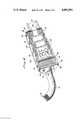
- FIG. 5is a section view along the line 5--5 of FIG. 1 illustrating the various stages in the operation of securing the connector elements together for a first embodiment of the invention.
- FIG. 6is a view along the line 5--5 of FIG. 1 illustrating the various steps in the operation of securing the connector elements together for a second embodiment of the invention.
- FIG. 7is a sectional view along the line 7--7 of FIG. 6.
- FIG. 8is a perspective view showing the connector assembly of FIG. 1 fully assembled.
- a riser cable 10 having from 300 to 2700 twisted pairs of wiresis shown.
- An end 12 of the cableis to be boarded for connection to, for example subscriber lines, while an end 14 of the cable is to be connected in a suitable manner to connector block cables 16.
- the connection of cables 10 and 16has been effected by random splicing the conductors of each.
- this inventionprovides a delta-shaped junction box connector assembly enclosure 18.
- This assemblyis formed with three extrusions or rails 20, 22, and 24 to which are secured a base plate or plates 26 and a suitable number of connector plates 28 for the size cable being terminated.
- the enclosureis sealed at the end opposite the cable by end plate 30 and at the cable end by plate 32 having a cable receiving opening 34 formed therein.
- a clamp assembly 36is mounted on cable 10 and secured to end plate 32 with bolts and nuts 78.
- Each plate 28has a plurality of ribbon-type connector elements 38 mounted in it.
- Amphenol 57 series connectorsare utilized, with each connector having 25 pairs of ribbon contacts. Since, for the preferred embodiment, there are eight connector elements 38 mounted in each plate 28, each plate may accommodate up to 200 twisted pairs of conductors.
- the conductors of a multi-conductor cableare grouped into bunches which are color coded for identification and are arranged in a predetermined order. Each bunch normally contains 100 twisted pairs of wire. It is therefore apparent that, as shown in FIG. 1, four connector elements 38 are required for for each conductor bunch.
- FIG. 4illustrates the connector elements to which each conductor block of the cable is connected for cables of various typical sizes. From FIG.
- the enclosure of this inventionis totally modular, permitting a greater or lesser number of connector elements to be utilized as required for different cable sizes. This is accomplished by changing the lengths of rails 20, 22 and 24, either changing the length of or adding additional plates 26, and by adding additional plates 28.
- each connector block cable 16also has 100 twisted pairs of conductors.
- Each of these cablesis terminated by four connector elements 42 which are of a type to mate with connector elements 38.
- theseare Amphenol 57 series blue ribbon-type connectors.
- FIGS. 1 and 5illustrate an alternative mechanism for preventing the spurious separation of the connector elements.
- This mechanismincludes a "U" shaped clip 50 having anchor projections 52 which is secured near the rear end of each connector element 38, and a spring clip 54 which is secured near the tip of each connector element. The manner in which these clips are utilized to secure a pair of mating connectors against accidental separation will be described shortly.
- hold down clips 46are initially secured to enclosure 18. While this may be done in the field, it is preferably done as part of the connector assembly operation.
- the first step in the field connection of a cable 16 to a cable 10is to connect each connector element 42 to the holddown clip 46 of the corresponding mating connector element 38 with a strain relief screw 124.
- the appearance of the assembly after this step in the operation has been completedis illustrated by the left-most pair of connector elements in FIG. 5; connector element 42 is pivoted into engagement with connector element 38.
- the appearance of the connector pair after this step in the operation has been completedis shown by the middle connector in FIG. 5.
- the final step in the operationinvolves the turning of a screw 132 which is inserted through an opening in the case of connector element 42 either at this time or during the assembly operation to secure connector 42 to stand-off element 76. These steps are repeated for each connector pair. To disconnect the cables, the operations performed are reversed.
- FIGS. 6 and 7illustrate an alternative holddown mechanism which permits connections to be effected more rapidly than with the embodiment of the invention shown in FIG. 5.
- clips 50 and 54are attached adjacent each connector element 38. Screw 48 and a screw in place of stand-off 76 may be used for attaching clips 50 and 54 respectively.
- the connector elementsWhen a pair of connector elements 38 and 42 are to be mated with this embodiment of the invention, the connector elements are first positioned as shown for the left-hand connector pair in FIG. 6 and pressure is then applied to the top of connector element 42 to force the connector elements together.
- the sides of the connector casingwhich lie in a plane parallel to the direction in which the connector element moves when being mated, act on cam projections 52 to open clip 50, the upright portions of which extend along the sidewalls of the casing.
- projections 52drop into openings 138 in the side of the connector casing to lock the back portion of the connector elements together.
- FIG. 7 and the right hand portion of FIG. 6show the elements as they appear when fully seated.
- a clip of suitable size having the shape of clip 50may be substituted for clip 54 if desired.
- the present random-splice techniquerequires approximately 80 hours of skilled technician time to connect a single riser cable, plus the time required for the ringing-out operation which may be another 24 hours.
- the corresponding operationsutilizing the apparatus of this invention, may be completed in from 4 to 8 hours by a somewhat less skilled operator. With the embodiment of the invention shown in FIGS. 6 and 7, the time required may be reduced even further.
- the ringing-out operationis performed at the factory, the 24 hours required for this operation is also eliminated further reducing the field time and labor required.
- a neat, easy to operate upon, and modularly expandable assemblyis thus provided. It has been found that the size of the package is roughly half of that required with the random splicing operation.
Landscapes
- Details Of Connecting Devices For Male And Female Coupling (AREA)
Abstract
Description
Claims (5)
Applications Claiming Priority (1)
| Application Number | Priority Date | Filing Date | Title |
|---|---|---|---|
| US05/448,476US3958850A (en) | 1972-04-28 | 1974-03-06 | Method and apparatus for connecting multi-conductor cables |
Related Parent Applications (1)
| Application Number | Title | Priority Date | Filing Date |
|---|---|---|---|
| US05/448,476DivisionUS3958850A (en) | 1972-04-28 | 1974-03-06 | Method and apparatus for connecting multi-conductor cables |
Publications (1)
| Publication Number | Publication Date |
|---|---|
| US4085992Atrue US4085992A (en) | 1978-04-25 |
Family
ID=23780454
Family Applications (1)
| Application Number | Title | Priority Date | Filing Date |
|---|---|---|---|
| US05/664,125Expired - LifetimeUS4085992A (en) | 1974-03-06 | 1976-03-05 | Method and apparatus for connecting multi-conductor cables |
Country Status (1)
| Country | Link |
|---|---|
| US (1) | US4085992A (en) |
Cited By (4)
| Publication number | Priority date | Publication date | Assignee | Title |
|---|---|---|---|---|
| US5167530A (en)* | 1992-01-14 | 1992-12-01 | Thomas & Betts Corporation | Jack cluster with offset mounting posts |
| US6024610A (en)* | 1998-01-14 | 2000-02-15 | The Whitaker Corporation | Cable connection assembly |
| US20050191901A1 (en)* | 1998-06-05 | 2005-09-01 | Adc Telecommunications, Inc. | Telecommunications patch panel with angled connector modules |
| US20070298652A1 (en)* | 2006-06-22 | 2007-12-27 | Clark Gordon P | Telecommunications patch |
Citations (9)
| Publication number | Priority date | Publication date | Assignee | Title |
|---|---|---|---|---|
| GB737662A (en)* | 1952-05-28 | 1955-09-28 | Cossor Ltd A C | Improvements in and relating to electric plug and socket connectors |
| US2871457A (en)* | 1956-10-26 | 1959-01-27 | Douglas Aircraft Co Inc | Mounting for electronic components |
| US2899669A (en)* | 1959-08-11 | Electrical connector | ||
| US2932000A (en)* | 1957-02-11 | 1960-04-05 | Stephen N Buchanan | Housing unit and mounting means |
| US3052863A (en)* | 1961-03-16 | 1962-09-04 | Ibm | Contact connector operating devices |
| US3110538A (en)* | 1962-02-26 | 1963-11-12 | Robertson Co H H | Mounting means for an electrical connector |
| US3345604A (en)* | 1966-04-08 | 1967-10-03 | Amp Inc | Electrical connector |
| US3566336A (en)* | 1968-08-30 | 1971-02-23 | Itt | Connector assembly |
| US3617985A (en)* | 1969-10-24 | 1971-11-02 | Motorola Inc | Accessory connector |
- 1976
- 1976-03-05USUS05/664,125patent/US4085992A/ennot_activeExpired - Lifetime
Patent Citations (9)
| Publication number | Priority date | Publication date | Assignee | Title |
|---|---|---|---|---|
| US2899669A (en)* | 1959-08-11 | Electrical connector | ||
| GB737662A (en)* | 1952-05-28 | 1955-09-28 | Cossor Ltd A C | Improvements in and relating to electric plug and socket connectors |
| US2871457A (en)* | 1956-10-26 | 1959-01-27 | Douglas Aircraft Co Inc | Mounting for electronic components |
| US2932000A (en)* | 1957-02-11 | 1960-04-05 | Stephen N Buchanan | Housing unit and mounting means |
| US3052863A (en)* | 1961-03-16 | 1962-09-04 | Ibm | Contact connector operating devices |
| US3110538A (en)* | 1962-02-26 | 1963-11-12 | Robertson Co H H | Mounting means for an electrical connector |
| US3345604A (en)* | 1966-04-08 | 1967-10-03 | Amp Inc | Electrical connector |
| US3566336A (en)* | 1968-08-30 | 1971-02-23 | Itt | Connector assembly |
| US3617985A (en)* | 1969-10-24 | 1971-11-02 | Motorola Inc | Accessory connector |
Cited By (22)
| Publication number | Priority date | Publication date | Assignee | Title |
|---|---|---|---|---|
| US5167530A (en)* | 1992-01-14 | 1992-12-01 | Thomas & Betts Corporation | Jack cluster with offset mounting posts |
| US6024610A (en)* | 1998-01-14 | 2000-02-15 | The Whitaker Corporation | Cable connection assembly |
| US7534135B2 (en) | 1998-06-05 | 2009-05-19 | Adc Telecommunications, Inc. | Telecommunications patch panel with angled connector modules |
| US7544090B2 (en) | 1998-06-05 | 2009-06-09 | Adc Telecommunications, Inc. | Telecommunications patch panel with angled connector modules |
| US7179119B2 (en) | 1998-06-05 | 2007-02-20 | Adc Telecommunications, Inc. | Telecommunications patch panel with angled connector modules |
| US7244144B2 (en) | 1998-06-05 | 2007-07-17 | Adc Telecommunications, Inc. | Telecommunications patch panel with angled connector modules |
| US9755381B2 (en) | 1998-06-05 | 2017-09-05 | Commscope Technologies Llc | Telecommunications patch panel with angled connector modules |
| US20080009182A1 (en)* | 1998-06-05 | 2008-01-10 | Adc Telecommunications, Inc. | Telecommunications patch panel with angled connector modules |
| US9356384B2 (en) | 1998-06-05 | 2016-05-31 | Commscope Technologies Llc | Telecommunications patch panel with angled connector modules |
| US9033728B2 (en) | 1998-06-05 | 2015-05-19 | Adc Telecommunications, Inc. | Telecommunications patch panel with angled connector modules |
| US20050191901A1 (en)* | 1998-06-05 | 2005-09-01 | Adc Telecommunications, Inc. | Telecommunications patch panel with angled connector modules |
| US20060228940A1 (en)* | 1998-06-05 | 2006-10-12 | Adc Telecommunications, Inc. | Telecommunications patch panel with angled connector modules |
| US20090176404A1 (en)* | 1998-06-05 | 2009-07-09 | Adc Telecommunications, Inc. | Telecommunications patch panel with angled connector modules |
| US8491331B2 (en) | 1998-06-05 | 2013-07-23 | Adc Telecommunications, Inc. | Telecommunications patch panel with angled connector modules |
| US8187027B2 (en) | 1998-06-05 | 2012-05-29 | Adc Telecommunications, Inc. | Telecommunications patch panel with angled connector modules |
| US7934948B2 (en) | 1998-06-05 | 2011-05-03 | Adc Telecommunications, Inc. | Telecommunications patch panel with angled connector modules |
| US7811122B2 (en) | 2006-06-22 | 2010-10-12 | Adc Telecommunications, Inc. | Telecommunications patch |
| US20100081319A1 (en)* | 2006-06-22 | 2010-04-01 | Adc Telecommunications, Inc. | Telecommunications Patch |
| US7607938B2 (en) | 2006-06-22 | 2009-10-27 | Adc Telecommunications | Telecommunications patch |
| US20080293294A1 (en)* | 2006-06-22 | 2008-11-27 | Adc Telecommunications, Inc. | Telecommunications patch |
| US7357667B2 (en) | 2006-06-22 | 2008-04-15 | Adc Telecommunications, Inc. | Telecommunications patch |
| US20070298652A1 (en)* | 2006-06-22 | 2007-12-27 | Clark Gordon P | Telecommunications patch |
Similar Documents
| Publication | Publication Date | Title |
|---|---|---|
| US5314350A (en) | Pluggable modular splicing connector and bridging adapter | |
| US4611875A (en) | Communication system cross-connect field power adapter | |
| JP3285213B2 (en) | Telephone connector | |
| CA1290038C (en) | Patch connector | |
| US4150867A (en) | Pre-wired terminal connecting block | |
| US5658166A (en) | Modular coupler arrangement for use in a building wiring distribution system | |
| US4261633A (en) | Wiring module for telephone jack | |
| KR100591673B1 (en) | Outlet and connecting blocks and plugs for telecommunications | |
| US5366388A (en) | Wiring distribution system and devices for building wiring | |
| US4403821A (en) | Wiring line tap | |
| US3702456A (en) | Electrical terminal block for interconnecting a plurality of conductors | |
| US3778750A (en) | Wire termination and splicing system | |
| CN1071280A (en) | The cross connection device that telecommunication system is used | |
| RU2144249C1 (en) | Modular connector with separable conductor locking device | |
| US4099819A (en) | Modular termination system for telecommunication devices | |
| US4538874A (en) | Modular jack assembly | |
| US4159159A (en) | Terminal module with dual binding post terminals | |
| US3958850A (en) | Method and apparatus for connecting multi-conductor cables | |
| US4657330A (en) | Field installable modular telephone connector | |
| US3715450A (en) | Junction box | |
| US3820056A (en) | Method and apparatus for connecting multi-conductor cables | |
| JPH01501825A (en) | electrical connectors | |
| US4085992A (en) | Method and apparatus for connecting multi-conductor cables | |
| USRE31714E (en) | Pre-wired terminal connecting block | |
| US4592614A (en) | Gender change connector |
Legal Events
| Date | Code | Title | Description |
|---|---|---|---|
| AS | Assignment | Owner name:ALLIED CORPORATION COLUMBIA ROAD AND PARK AVENUE, Free format text:ASSIGNMENT OF ASSIGNORS INTEREST.;ASSIGNOR:BUNKER RAMO CORPORATION A CORP. OF DE;REEL/FRAME:004149/0365 Effective date:19820922 | |
| AS | Assignment | Owner name:CANADIAN IMPERIAL BANK OF COMMERCE, NEW YORK AGENC Free format text:SECURITY INTEREST;ASSIGNOR:AMPHENOL CORPORATION;REEL/FRAME:004879/0030 Effective date:19870515 | |
| AS | Assignment | Owner name:AMPHENOL CORPORATION, LISLE, ILLINOIS A CORP. OF D Free format text:ASSIGNMENT OF ASSIGNORS INTEREST.;ASSIGNOR:ALLIED CORPORATION, A CORP. OF NY;REEL/FRAME:004844/0850 Effective date:19870602 Owner name:AMPHENOL CORPORATION, A CORP. OF DE, ILLINOIS Free format text:ASSIGNMENT OF ASSIGNORS INTEREST;ASSIGNOR:ALLIED CORPORATION, A CORP. OF NY;REEL/FRAME:004844/0850 Effective date:19870602 | |
| AS | Assignment | Owner name:AMPHENOL CORPORATION, 358 HALL AVENUE, WALLINGFORD Free format text:SECURITY INTEREST;ASSIGNOR:CANADIAN IMPERIAL BANK OF COMMERCE, AS AGENT;REEL/FRAME:004912/0120 Effective date:19880623 Owner name:AMPHENOL INTERCONNECT PRODUCTS CORPORATION, A DE. Free format text:ASSIGNMENT OF ASSIGNORS INTEREST.;ASSIGNOR:AMPHENOL CORPORATION;REEL/FRAME:004925/0469 Effective date:19880624 Owner name:MORGAN GUARANTY TRUST COMPANY, NEW YORK Free format text:SECURITY INTEREST;ASSIGNOR:AMPHENOL INTERCONNECT PRODUCTS CORPORATION, A CORP. OF DE;REEL/FRAME:004939/0758 Effective date:19880615 Owner name:AMPHENOL CORPORATION,CONNECTICUT Free format text:SECURITY INTEREST;ASSIGNOR:CANADIAN IMPERIAL BANK OF COMMERCE, AS AGENT;REEL/FRAME:004912/0120 Effective date:19880623 | |
| AS | Assignment | Owner name:AMPHENOL INTERCONNECT PRODUCTS CORPORATION, A DE C Free format text:TO RELEASE BY SECURED PART OF A SECURITY AGREEMENT RECORDED AT REEL 4939 FRAME 0758.;ASSIGNOR:MORGAN GUARANTY TRUST COMPANY OF NEW YORK;REEL/FRAME:006034/0352 Effective date:19911118 Owner name:BANKERS TRUST COMPANY Free format text:SECURITY INTEREST;ASSIGNORS:AMPHENOL INTERCONNECT PRODUCTS CORPORATION;AMPHENOL INTERNATIONAL LTD.;PYLE INC.;AND OTHERS;REEL/FRAME:006031/0651 Effective date:19911118 | |
| AS | Assignment | Owner name:AMPHENOL CORPORATION A CORP. OF DELAWARE Free format text:RELEASED BY SECURED PARTY;ASSIGNOR:CANADIAN IMPERIAL BANK OF COMMERCE;REEL/FRAME:006147/0887 Effective date:19911114 | |
| AS | Assignment | Owner name:AMPHENOL INTERCONNECT PRODUCTS CORP. AND OTHER SUB Free format text:RELEASE BY SECURED PARTY;ASSIGNOR:BANKERS TRUST COMPANY;REEL/FRAME:007317/0071 Effective date:19950104 |