US4084595A - Transcutaneous nerve stimulator - Google Patents
Transcutaneous nerve stimulatorDownload PDFInfo
- Publication number
- US4084595A US4084595AUS05/705,677US70567776AUS4084595AUS 4084595 AUS4084595 AUS 4084595AUS 70567776 AUS70567776 AUS 70567776AUS 4084595 AUS4084595 AUS 4084595A
- Authority
- US
- United States
- Prior art keywords
- resistance
- direct current
- output
- current voltage
- source
- Prior art date
- Legal status (The legal status is an assumption and is not a legal conclusion. Google has not performed a legal analysis and makes no representation as to the accuracy of the status listed.)
- Expired - Lifetime
Links
Images
Classifications
- A—HUMAN NECESSITIES
- A61—MEDICAL OR VETERINARY SCIENCE; HYGIENE
- A61N—ELECTROTHERAPY; MAGNETOTHERAPY; RADIATION THERAPY; ULTRASOUND THERAPY
- A61N1/00—Electrotherapy; Circuits therefor
- A61N1/18—Applying electric currents by contact electrodes
- A61N1/32—Applying electric currents by contact electrodes alternating or intermittent currents
- A61N1/36—Applying electric currents by contact electrodes alternating or intermittent currents for stimulation
- A61N1/36014—External stimulators, e.g. with patch electrodes
- A61N1/36021—External stimulators, e.g. with patch electrodes for treatment of pain
Definitions
- This inventionrelates generally to electromedical therapeutic apparatus and more specifically to an improved transcutaneous nerve stimulating apparatus for alleviating pain through the selective application of variable amplitude, variable pulse rate, variable pulse width electrical pulses to the skin in the area in which pain is experienced. It has been found that a proper application of such pulses serves to block the nerve responses and produce a beneficial effect.
- an integrated circuit timing networkenergized by a rechargeable direct current battery is connected to an external resistor/capacitor charging circuit to form an astable oscillator whose pulse width and pulse rate are manually adjustable.
- the oscillatoris coupled through a transistor current switching network and a step-up transformer to first and second pairs of electrodes.
- a current balancing networkcoupled between the output of the transformer and the electrodes allows the transformer output to be apportioned between the first and second electrode pairs.
- Another networkincluding a light emitting diode, is coupled to the integrated circuit timing network and is arranged to blink on and off when the rechargeable battery potential falls below a prearranged value, thus signaling the need for recharging.
- Another object of this inventionis to provide a portable transcutaneous nerve stimulator in which the amplitude, rate and pulse width of the applied electrical signals are selectively variable over a range of values by the patient.
- Still another object of the inventionis to provide an electronic pulse generator having a rechargable energy supply along with means for visually indicating the fact that the state of charge on the energy supply has deteriorated below a predetermined threshold value.
- FIG. 1is a pictorial drawing of the apparatus, showing the various controls.
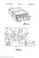
- FIG. 2is a schematic diagram of the circuitry used in the preferred embodiment.
- the packageincludes a substantially rectangular casing 1 which may be molded or otherwise formed from a suitable material such as plastic.
- the size of the packagemay, for example, be one inch thick by 3, inches wide by five inches long.
- a step-like projection or extension 2which is integrally formed with the rest of the case 1.
- a plurality of thumb-wheel type control knobs 3, 4, 5 and 6are mounted on shafts (not shown) which extend through apertures formed in the vertical riser 7. As will be explained more fully hereinbelow when the details of the electronic circuitry are described, these control knobs permit the user to control the rate, amplitude and pulse width of the electrical stimulating pulses produced by the transcutaneous nerve stimulator of this invention, as well as to control the balance of the electrical energy between first and second pairs of electrodes.
- thumb-wheel or knob 3controls the balance of potential between first and second pairs of electrodes.
- thumb-wheel 4may be used to adjust the width of the stimulating pulses applied to the skin of the user via the electrodes (not shown).
- Thumb-wheels 5 and 6respectively control the pulse rate and amplitude of the stimulating pulses.
- thumb-wheel 6controls an "on-off" switch which is connected between the power for the unit and the electrical circuitry energized thereby.
- First and second pairs of receptacles or jacks 9 and 10are formed in the display panel 8 and extend into the casing 1 where they connect to operative elements of the electrical circuitry housed within the casing. Also illustrated in FIG. 1, on the face of the display panel 8 is an indicator 11 which, in the preferred embodiment, comprises a light-emitting diode (LED). As will be explained further, the indicator 11 serves to apprise the user of the charge condition of the energy source used to power the transcutaneous nerve stimulator of this invention.
- LEDlight-emitting diode
- the power source for the present inventionis preferably a rechargeable DC battery pack (not shown).
- This packis designed to be inserted and removed from its operative location within the housing 1 through an opening (not shown) formed in the rear end 12 of the housing. Because of its size and weight (approximately nine ounces) it can be seen that the device is readily portable and conveniently can be carried in a shirt pocket or, if desired, secured by a belt to a desired location on the body of the user.
- a DC rechargeable battery 13which is connected between the B+ bus 14 and a ground bus 15.
- the battery 13may be such as to produce a potential difference of approximately five volts across its terminals when fully charged, but limitation to such a value is not intended.
- the B+ bus 14is connected by a conductor 16 to the V cc bus 17.
- the chip 18may be a Type 556 dual timer device such as manufactured by the Fairchild Semiconductor Division of the Fairchild Camera and Instrument Corporation.
- the chip 18has 14 input/output pins which are respectively identified by the small numerals 1 through 14 located adjacent to the rectangular block representing the Type 556 chip.
- One desiring additional information concerning the construction and mode of operation of this integrated circuit chipis referred to the application notes provided by the manufacturers. For example, reference is made to the handbook entitled "Fairchild Linear Integrated Circuits" copyrighted in 1976 Lk and published by the Fairchild Camera and Instrument Company.
- Pin 1 of the chip 18is connected to a junction 19 between a resistor 20 and a semiconductor diode 21.
- the other terminal of resistor 20is connected to a junction point 22 between the series combination of a resistor 23 and a resistor 24.
- Resistors 23 and 24are serially connected with a capacitor 25 between the Vcc bus 17 and the ground bus 15.
- Pin 2 and Pin 6 of the chip 18are connected together and to the junction point 26 formed between the resistor 24 and the capacitor 25.
- Pin 3 of IC chip 18is coupled by means of a capacitor 27 to the ground bus 15.
- Pin 4 of chip 18is connected by a conductor 28 to the V cc bus 17.
- Pin 5 of chip 18is connected through a series combination of a resistor 29 and a semiconductor diode 30 to a junction point 31 to which the cathode of the diode 21 is connected. Connected between junction 31 and the ground bus 15 is a light-emitting diode 32. Pin 7 of chip 18 is connected directly to the ground bus 15 by a conductor 33.
- Pin 8 and Pin 12 of the chip 18are connected together by a jumper 34 at the junction point 35 which, in turn, is connected by a conductor 36 to a junction 37 formed between a capacitor 38 and a series combination of resistor 39 and a potentiometer 40.
- the end of potentiometer 40is connected to the Vcc bus 17.
- Coupled between the V cc bus 17 and Pin 9 of chip 18is a series combination of first and second resistors 41 and 42 and a potentiometer 43.
- Pin 10 and Pin 14 of chip 18are connected together and to the V cc bus 17 by way of a conductor 44.
- Pin 13 of chip 18is coupled through a series resistor 45 and a parallel combination of a resistor 46 and a potentiometer 47 to a conductor 48 which is connected to the junction point 37.
- a capacitor 49is connected directly in parallel with the voltage source 13 between the B+ bus 14 and the ground bus 15.
- the wiper arm 50 of the potentiometer 43is connected in common with the base electrodes of a plurality of transistors including PNP transistors 51, 52 and 53.
- the emitter electrodes of each of these transistorsare tied directly to the B+ bus 14 and the collector electrodes thereof are connected in common to a junction point 54.
- the primary winding 55 of a step-up transformer 56is connected between the junction 54 and the ground bus 15.
- the step-up transformer 56has a secondary winding 57 and connected in parallel with this secondary winding is a capacitor 58.
- the upper terminal 59 of secondary winding 57is connected to the wiper arm 60 of a balancing potentiometer 61. Opposite ends of the potentiometer 61 are connected to the jack terminals 9 and 10 (FIG. 1).
- the Type 556 integrated circuit chip 18is a dual timing circuit. More specifically, contained within the chip 18 are two identical timer units. In the figure, Pins 1 through 7 provide the input, output and control connections to the first of the two timer circuits contained within chip 18, while Pins 8 through 14 provide the input, output and control functions for the second of the two timer units. In the preferred embodiment, the first of the two timer units is used to provide a visual indication that the battery has discharged to a point where recharging thereof is in order.
- the first timer unitis connected so as to operate as an astable multivibrator whose output at Pin 5 is coupled through a resistor 29 and the diode 30 to the anode electrode of LED 32.
- the junction 31is alternately clamped at ground and allowed to assume a relatively high potential to thereby cause the LED 32 to turn on and off at a rate determined by the parameters of resistors 23, 24 and capacitor 25.
- the "reset" Pin 4is tied to a high potential by way of conductor 28 and Pin 2 and Pin 6 are connected together and to the junction point 26 between the capacitor 25 and the resistor 24.
- V D32is the voltage drop across the LED
- V d21is the drop across diode 21
- R20 and R23 and R25are expressed in ohms.
- V bis the battery potential.
- the second of the two timer units contained on the IC chip 18along with the circuitry shown to the right of the chip 18 in FIG. 2 provides the nerve stimulating output pulses and the means for adjusting the amplitude, duration, frequency and balance thereof.
- the connection between the trigger Pin 8 and the threshold Pin 12 of the chip 18 (conductor 34)causes the second timer unit on chip 18 to also operate in an astable mode.
- the reset Pin 10 of chip 18is connected by means of conductor 44 to a relatively high potential.
- the output from the astable multivibratorappears at Pin 9.
- the potentiometer 40in series with the resistor 39 controls the charging time of the capacitor 38.
- potentiometer 40, resistor 39 and capacitor 38are of such a value that the frequency of the output signals can be made to vary between 10 and 100 Hz.
- the component valuesare chosen such that the pulse duration can be made to vary between 10 and 500 microseconds.
- the values of resistors 45 and 46are chosen to give the desired end points for permissible pulse width.
- the output signals from the second timer unit on the chip 18appear at Pin 9 and swing between ground and a positive value determined by the ohmic values of resistors 40, 41 and 42 and the potentiometer 43.
- the output signalsare used to control the conduction state of the parallel connected transistors 51, 52 and 53.
- the conduction level in these three transistorsmay be controlled by the setting of the wiper arm 50 on the potentiometer 43.
- the setting of the wiper arm 50determines the amplitude of the output pulses used to stimulate the body.
- the amplitudecan be made to vary between 0 V and 35 V.
- resistors of identical ohmic valuesin series with the emitters of these transistors.
- the changing current caused by the application of the timer output pulses to the parallel transistors 51, 52 and 53causes a voltage to be induced across the secondary winding 57 of the transformer 56.
- the capacitor 58 connected in parallel with the secondary winding 57serves to protect the transistors 51, 52 and 53 when an open circuit exists between the electrode jacks 9 and 10.
- the potentiometer 61provides a means for balancing the distribution of load current as between the electrodes connected to jacks 10 and the electrodes connected to the jacks 9.
- this inventionapparatus for producing variable amplitude, variable pulse width, variable frequency output signals to first and second electrode pairs.
- the inventionincludes circuitry for indicating when the level of charge on the rechargeable power pack has dropped below a given threshold.
- the present inventionfully accomplishes its intended objects. While there has been disclosed and described in detail a preferred embodiment of the invention, that has been done by way of illustration, and not by way of limitation. It is realized that the transcutaneous nerve stimulator of the present invention can assume additional forms, and it is intended to include within the scope of the appended claims all modifications and variations naturally occurring to those skilled in the art.
Landscapes
- Health & Medical Sciences (AREA)
- Life Sciences & Earth Sciences (AREA)
- Biomedical Technology (AREA)
- Biophysics (AREA)
- Heart & Thoracic Surgery (AREA)
- Engineering & Computer Science (AREA)
- Pain & Pain Management (AREA)
- Nuclear Medicine, Radiotherapy & Molecular Imaging (AREA)
- Radiology & Medical Imaging (AREA)
- Animal Behavior & Ethology (AREA)
- General Health & Medical Sciences (AREA)
- Public Health (AREA)
- Veterinary Medicine (AREA)
- Electrotherapy Devices (AREA)
Abstract
Description
Claims (7)
Priority Applications (1)
| Application Number | Priority Date | Filing Date | Title |
|---|---|---|---|
| US05/705,677US4084595A (en) | 1976-07-15 | 1976-07-15 | Transcutaneous nerve stimulator |
Applications Claiming Priority (1)
| Application Number | Priority Date | Filing Date | Title |
|---|---|---|---|
| US05/705,677US4084595A (en) | 1976-07-15 | 1976-07-15 | Transcutaneous nerve stimulator |
Publications (1)
| Publication Number | Publication Date |
|---|---|
| US4084595Atrue US4084595A (en) | 1978-04-18 |
Family
ID=24834492
Family Applications (1)
| Application Number | Title | Priority Date | Filing Date |
|---|---|---|---|
| US05/705,677Expired - LifetimeUS4084595A (en) | 1976-07-15 | 1976-07-15 | Transcutaneous nerve stimulator |
Country Status (1)
| Country | Link |
|---|---|
| US (1) | US4084595A (en) |
Cited By (26)
| Publication number | Priority date | Publication date | Assignee | Title |
|---|---|---|---|---|
| US4233986A (en)* | 1978-07-18 | 1980-11-18 | Agar Ginosar Electronics And Metal Products | Apparatus and method for controlling pain by transcutaneous electrical stimulation (TES) |
| US4256116A (en)* | 1978-07-03 | 1981-03-17 | Technion Research And Development Foundation, Limited | Transcutaneous pain reliever |
| EP0057048A1 (en)* | 1981-01-08 | 1982-08-04 | Chattanooga Corporation | Electrical therapeutic apparatus |
| US4453547A (en)* | 1981-04-06 | 1984-06-12 | Physio Technology, Inc. | T-Wave inhibiting system |
| US4509521A (en)* | 1983-01-31 | 1985-04-09 | Barry Terrence J | Headache relief method |
| USD279709S (en) | 1982-07-26 | 1985-07-16 | Staodynamics, Inc. | Transcutaneous nerve stimulating device |
| USD280341S (en) | 1982-06-25 | 1985-08-27 | Theratronics, Inc. | Muscle stimulator |
| US4558703A (en)* | 1982-05-27 | 1985-12-17 | Hermann Mark | Vestibular stimulation method |
| US4595010A (en)* | 1984-03-12 | 1986-06-17 | Bio-Research Associates, Inc. | Electrical muscle stimulator |
| US4690146A (en)* | 1985-06-17 | 1987-09-01 | Chattanooga Corporation | Neuromuscular stimulating apparatus |
| US4832032A (en)* | 1985-08-16 | 1989-05-23 | La Jolla Technology, Inc. | Electrical apparatus protective interconnect |
| US4913148A (en)* | 1985-07-31 | 1990-04-03 | Hepax Limited | Method for the treatment of herpes simplex and herpes zoster |
| US4919140A (en)* | 1988-10-14 | 1990-04-24 | Purdue Research Foundation | Method and apparatus for regenerating nerves |
| US5218960A (en)* | 1990-07-18 | 1993-06-15 | Laboratoires Deglaude | Electro-stimulation apparatus |
| US5899922A (en)* | 1993-05-28 | 1999-05-04 | Loos; Hendricus G. | Manipulation of nervous systems by electric fields |
| US6081744A (en)* | 1993-05-28 | 2000-06-27 | Loos; Hendricus G. | Electric fringe field generator for manipulating nervous systems |
| US6167304A (en)* | 1993-05-28 | 2000-12-26 | Loos; Hendricus G. | Pulse variability in electric field manipulation of nervous systems |
| US6662051B1 (en) | 2000-03-31 | 2003-12-09 | Stephen A. Eraker | Programmable pain reduction device |
| EP1374825A1 (en)* | 2002-05-28 | 2004-01-02 | Shin'ichi Kawamata | Apparatus for generating composite wave to reaction point |
| US20040167589A1 (en)* | 2003-02-22 | 2004-08-26 | Chester Heath | Viral-inhibiting apparatus and methods |
| US20070255342A1 (en)* | 2004-09-23 | 2007-11-01 | Laufer Michael D | Location and deactivation of muscles |
| US20080215113A1 (en)* | 2007-01-31 | 2008-09-04 | Pawlowicz John S | Devices and methods for transcutaneous electrical neural stimulation |
| US20090101139A1 (en)* | 2007-10-23 | 2009-04-23 | Karell Manuel L | Nasal dilator combined with stimulator |
| US20090132003A1 (en)* | 2005-10-21 | 2009-05-21 | Purdue Research Foundation | Wireless Electrical Stimulation of Neural Injury |
| US20090254148A1 (en)* | 2005-10-21 | 2009-10-08 | Borgens Richard B | Telemetrically Controllable System for Treatment of Nervous Sytem Injury |
| USD1002361S1 (en)* | 2021-12-09 | 2023-10-24 | Coloplast A/S | Implant tray and a retainer cap of a nerve stimulator package |
Citations (7)
| Publication number | Priority date | Publication date | Assignee | Title |
|---|---|---|---|---|
| US1257555A (en)* | 1914-06-25 | 1918-02-26 | Vreeland Apparatus Company | Method of producing analgesia. |
| US3109430A (en)* | 1959-01-29 | 1963-11-05 | Electronic Aids Inc | Cardiac nerve control device |
| US3255753A (en)* | 1963-03-22 | 1966-06-14 | Nat Patent Dev Corp | Electrical sleep machine and sleep inducing method |
| US3464416A (en)* | 1967-08-25 | 1969-09-02 | Williams Instruments | Sleep inducing method and headpiece |
| US3669119A (en)* | 1970-03-04 | 1972-06-13 | American Clinic Inc | Adjustable electrode means for a sleep inducing machine |
| US3718132A (en)* | 1970-03-26 | 1973-02-27 | Neuro Syst Inc | Electrotherapy machine |
| US3911930A (en)* | 1974-03-01 | 1975-10-14 | Stimulation Tech | Method and structure of preventing and treating ileus, and reducing acute pain by electrical pulse stimulation |
- 1976
- 1976-07-15USUS05/705,677patent/US4084595A/ennot_activeExpired - Lifetime
Patent Citations (7)
| Publication number | Priority date | Publication date | Assignee | Title |
|---|---|---|---|---|
| US1257555A (en)* | 1914-06-25 | 1918-02-26 | Vreeland Apparatus Company | Method of producing analgesia. |
| US3109430A (en)* | 1959-01-29 | 1963-11-05 | Electronic Aids Inc | Cardiac nerve control device |
| US3255753A (en)* | 1963-03-22 | 1966-06-14 | Nat Patent Dev Corp | Electrical sleep machine and sleep inducing method |
| US3464416A (en)* | 1967-08-25 | 1969-09-02 | Williams Instruments | Sleep inducing method and headpiece |
| US3669119A (en)* | 1970-03-04 | 1972-06-13 | American Clinic Inc | Adjustable electrode means for a sleep inducing machine |
| US3718132A (en)* | 1970-03-26 | 1973-02-27 | Neuro Syst Inc | Electrotherapy machine |
| US3911930A (en)* | 1974-03-01 | 1975-10-14 | Stimulation Tech | Method and structure of preventing and treating ileus, and reducing acute pain by electrical pulse stimulation |
Cited By (32)
| Publication number | Priority date | Publication date | Assignee | Title |
|---|---|---|---|---|
| US4256116A (en)* | 1978-07-03 | 1981-03-17 | Technion Research And Development Foundation, Limited | Transcutaneous pain reliever |
| US4233986A (en)* | 1978-07-18 | 1980-11-18 | Agar Ginosar Electronics And Metal Products | Apparatus and method for controlling pain by transcutaneous electrical stimulation (TES) |
| EP0057048A1 (en)* | 1981-01-08 | 1982-08-04 | Chattanooga Corporation | Electrical therapeutic apparatus |
| US4580570A (en)* | 1981-01-08 | 1986-04-08 | Chattanooga Corporation | Electrical therapeutic apparatus |
| US4453547A (en)* | 1981-04-06 | 1984-06-12 | Physio Technology, Inc. | T-Wave inhibiting system |
| US4558703A (en)* | 1982-05-27 | 1985-12-17 | Hermann Mark | Vestibular stimulation method |
| USD280341S (en) | 1982-06-25 | 1985-08-27 | Theratronics, Inc. | Muscle stimulator |
| USD279709S (en) | 1982-07-26 | 1985-07-16 | Staodynamics, Inc. | Transcutaneous nerve stimulating device |
| US4509521A (en)* | 1983-01-31 | 1985-04-09 | Barry Terrence J | Headache relief method |
| US4595010A (en)* | 1984-03-12 | 1986-06-17 | Bio-Research Associates, Inc. | Electrical muscle stimulator |
| US4690146A (en)* | 1985-06-17 | 1987-09-01 | Chattanooga Corporation | Neuromuscular stimulating apparatus |
| US4913148A (en)* | 1985-07-31 | 1990-04-03 | Hepax Limited | Method for the treatment of herpes simplex and herpes zoster |
| US4832032A (en)* | 1985-08-16 | 1989-05-23 | La Jolla Technology, Inc. | Electrical apparatus protective interconnect |
| US4919140A (en)* | 1988-10-14 | 1990-04-24 | Purdue Research Foundation | Method and apparatus for regenerating nerves |
| US5218960A (en)* | 1990-07-18 | 1993-06-15 | Laboratoires Deglaude | Electro-stimulation apparatus |
| US6081744A (en)* | 1993-05-28 | 2000-06-27 | Loos; Hendricus G. | Electric fringe field generator for manipulating nervous systems |
| US5899922A (en)* | 1993-05-28 | 1999-05-04 | Loos; Hendricus G. | Manipulation of nervous systems by electric fields |
| US6167304A (en)* | 1993-05-28 | 2000-12-26 | Loos; Hendricus G. | Pulse variability in electric field manipulation of nervous systems |
| US6662051B1 (en) | 2000-03-31 | 2003-12-09 | Stephen A. Eraker | Programmable pain reduction device |
| EP1374825A1 (en)* | 2002-05-28 | 2004-01-02 | Shin'ichi Kawamata | Apparatus for generating composite wave to reaction point |
| US20040167589A1 (en)* | 2003-02-22 | 2004-08-26 | Chester Heath | Viral-inhibiting apparatus and methods |
| US20070073372A1 (en)* | 2003-02-22 | 2007-03-29 | Chester Heath | Viral-inhibiting apparatus and methods |
| US20070255342A1 (en)* | 2004-09-23 | 2007-11-01 | Laufer Michael D | Location and deactivation of muscles |
| US8521295B2 (en)* | 2004-09-23 | 2013-08-27 | Michael D. Laufer | Location and deactivation of muscles |
| US8909347B2 (en) | 2004-09-23 | 2014-12-09 | Michael D. Laufer | Location and deactivation of muscles |
| US20090132003A1 (en)* | 2005-10-21 | 2009-05-21 | Purdue Research Foundation | Wireless Electrical Stimulation of Neural Injury |
| US20090254148A1 (en)* | 2005-10-21 | 2009-10-08 | Borgens Richard B | Telemetrically Controllable System for Treatment of Nervous Sytem Injury |
| US20080215113A1 (en)* | 2007-01-31 | 2008-09-04 | Pawlowicz John S | Devices and methods for transcutaneous electrical neural stimulation |
| US7844340B2 (en) | 2007-01-31 | 2010-11-30 | Pawlowicz Iii John S | Devices and methods for transcutaneous electrical neural stimulation |
| US20090101139A1 (en)* | 2007-10-23 | 2009-04-23 | Karell Manuel L | Nasal dilator combined with stimulator |
| US7873421B2 (en) | 2007-10-23 | 2011-01-18 | Manuel L Karell | Nasal dilator adapted to provide electrical stimulation |
| USD1002361S1 (en)* | 2021-12-09 | 2023-10-24 | Coloplast A/S | Implant tray and a retainer cap of a nerve stimulator package |
Similar Documents
| Publication | Publication Date | Title |
|---|---|---|
| US4084595A (en) | Transcutaneous nerve stimulator | |
| US4324253A (en) | Transcutaneous pain control and/or muscle stimulating apparatus | |
| US4006396A (en) | Universal battery charging apparatus | |
| US4283712A (en) | Portable exercise totalizer | |
| US4153059A (en) | Urinary incontinence stimulator system | |
| US4102344A (en) | Stimulator apparatus for internal body organ | |
| CA1200285A (en) | Electrical stimulating apparatus | |
| US4256116A (en) | Transcutaneous pain reliever | |
| US4408617A (en) | Apparatus for detecting the acupuncture points on a patient and for applying electrical stimulating signals to the detected points | |
| US4609860A (en) | Battery charger having automatic deep discharge mode | |
| US3311111A (en) | Controllable electric body tissue stimulators | |
| US5998966A (en) | Microcontrolled battery charger | |
| US4926880A (en) | Method for relieving sinus and nasal congestion utilizing microcurrents | |
| US4665920A (en) | Skeletal tissue stimulator and a low voltage oscillator circuit for use therein | |
| JP2848599B2 (en) | Device for supplying high-voltage current to chemical solutions | |
| US3791373A (en) | Portable electroanesthesia device with automatic power control | |
| EP0155091A1 (en) | Apparatus and method for inhibiting nasal secretions | |
| EP0369414A1 (en) | Dental anesthesia apparatus | |
| WO1991015262A1 (en) | A method for the electrical stimulation of a group of muscles in order to improve their appearance, and apparatus for carrying out the method | |
| US3871383A (en) | Power supply | |
| US3547127A (en) | Cardiac pacemaker with regulated power supply | |
| EP0000477A1 (en) | Mandible stimulator | |
| US4052978A (en) | Electro-therapy apparatus | |
| CA1319737C (en) | Acupuncture locating device | |
| US4230121A (en) | Electrical body stimulator |
Legal Events
| Date | Code | Title | Description |
|---|---|---|---|
| AS | Assignment | Owner name:NEUROMEDICS, INC., A CORP. OF TX Free format text:ASSIGNMENT OF ASSIGNORS INTEREST.;ASSIGNOR:MED GENERAL, INC.,;REEL/FRAME:003834/0020 Effective date:19801229 Owner name:NEUROMEDICS, INC., A CORP. OF TX, TEXAS Free format text:ASSIGNMENT OF ASSIGNORS INTEREST;ASSIGNOR:MED GENERAL, INC.,;REEL/FRAME:003834/0020 Effective date:19801229 | |
| AS | Assignment | Owner name:FIRST FREEPORT NATIONAL BANK Free format text:SECURITY INTEREST;ASSIGNORS:INTERMEDICS, INC.;INTERMEDICS CARDIASSIST, INC.;INTERMEDICS INTRAOCULAR, INC.;AND OTHERS;REEL/FRAME:004303/0077 Effective date:19840726 Owner name:TRUST COMPANY BANK Free format text:SECURITY INTEREST;ASSIGNORS:INTERMEDICS, INC.;INTERMEDICS CARDIASSIST, INC.;INTERMEDICS INTRAOCULAR, INC.;AND OTHERS;REEL/FRAME:004303/0077 Effective date:19840726 Owner name:CHASE MANHATTAN BANK, N.A., THE Free format text:SECURITY INTEREST;ASSIGNORS:INTERMEDICS, INC.;INTERMEDICS CARDIASSIST, INC.;INTERMEDICS INTRAOCULAR, INC.;AND OTHERS;REEL/FRAME:004303/0077 Effective date:19840726 Owner name:FIRST NATIONAL BANK OF CHICAGO, THE Free format text:SECURITY INTEREST;ASSIGNORS:INTERMEDICS, INC.;INTERMEDICS CARDIASSIST, INC.;INTERMEDICS INTRAOCULAR, INC.;AND OTHERS;REEL/FRAME:004303/0077 Effective date:19840726 Owner name:CITIBANK, N.A., AS AGENT Free format text:SECURITY INTEREST;ASSIGNORS:INTERMEDICS, INC.;INTERMEDICS CARDIASSIST, INC.;INTERMEDICS INTRAOCULAR, INC.;AND OTHERS;REEL/FRAME:004303/0077 Effective date:19840726 Owner name:BRAZOSPORT BANK OF TEXAS Free format text:SECURITY INTEREST;ASSIGNORS:INTERMEDICS, INC.;INTERMEDICS CARDIASSIST, INC.;INTERMEDICS INTRAOCULAR, INC.;AND OTHERS;REEL/FRAME:004303/0077 Effective date:19840726 Owner name:BANK OF AMERICA NATIONAL TRUST AND SAVINGS ASSOCIA Free format text:SECURITY INTEREST;ASSIGNORS:INTERMEDICS, INC.;INTERMEDICS CARDIASSIST, INC.;INTERMEDICS INTRAOCULAR, INC.;AND OTHERS;REEL/FRAME:004303/0077 Effective date:19840726 | |
| AS | Assignment | Owner name:B.A. LEASING CORPORATION Free format text:SECURITY INTEREST;ASSIGNORS:INTERMEDICS, INC., A CORP. OF TEXAS;INTERMEDICS CARDIASSIST, INC.;INTERMEDICS INTRAOCULAR, INC., A CORP. OF TEXAS;AND OTHERS;REEL/FRAME:004449/0424 Effective date:19850703 Owner name:CITIBANK, N.A. Free format text:SECURITY INTEREST;ASSIGNORS:INTERMEDICS, INC., A TX CORP;INTERMEDICS CARDIASSIST, INC., A TX CORP.;INTERMEDICS INTRAOCULAR, INC., A TX CORP.;AND OTHERS;REEL/FRAME:004434/0728 Effective date:19850703 Owner name:CHASE COMMERCIAL CORPORATION Free format text:SECURITY INTEREST;ASSIGNORS:INTERMEDICS, INC., A CORP. OF TEXAS;INTERMEDICS CARDIASSIST, INC., A CORP OF TX.;INTERMEDICS INTRAOCULAR, INC., A CORP. OF TEXAS;AND OTHERS;REEL/FRAME:004449/0501 Effective date:19850703 Owner name:CITICORP MILTILEASE (SEF), INC. Free format text:SECURITY INTEREST;ASSIGNORS:INTERMEDICS, INC.;INTERMEDICS CARDIASSIST, INC.;INTERMEDICS INTRAOCULAR, INC., A CORP. OF TEXAS;AND OTHERS;REEL/FRAME:004452/0900 Effective date:19850703 | |
| AS | Assignment | Owner name:INTERMEDICS, INC., INTERMEDICS CARDIASSIST, INC., Free format text:SAID PARTIES RECITES OBLIGATIONS RECITED IN SECURITY AGREEMENT RECORDED SEPTEMBER 17, 1984 REEL 4303 FRAMES 077-127 HAVE BEEN PAID IN FULL ALL;ASSIGNOR:CITIBANK, N.A., INDIVIDUALLY AND AS AGENT FOR BANK OF AMERICA NATIONAL TRUST AND SAVINGS ASSOCIATION, THE CHASE MANHATTAN BANK, N.A., THE FIRST NATIONAL BANK OF CHICAGO, TRUST COMPANY BANK, FIRST FREEPORT NATIONAL BANK OF BRAZOSPORT BANK OF TEXAS;REEL/FRAME:004592/0424 Effective date:19860502 Owner name:INTERMEDICS, INC. Free format text:RELEASED BY SECURED PARTY;ASSIGNOR:CITICORP MULTILEASE (SEF), INC.;REEL/FRAME:004576/0516 Effective date:19860515 Owner name:INTERMEDICS, INC., INTERMEDICS CARDIASSIST, INC., Free format text:SECURED PARTY HEREBY RELEASE THE SECURITY INTEREST IN AGREEMENT RECORDED AUGUST 5, 1985. REEL 4434 FRAMES 728-782;ASSIGNOR:CITIBANK, N.A.;REEL/FRAME:004592/0394 Effective date:19860502 | |
| AS | Assignment | Owner name:INTERMEDICS, INC., A TEXAS CORP. Free format text:RELEASED BY SECURED PARTY;ASSIGNOR:B. A. LEASING CORPORATION;REEL/FRAME:004603/0607 Effective date:19860813 Owner name:INTERMEDICS CARDIASSIST, INC., A TEXAS CORP. Free format text:RELEASED BY SECURED PARTY;ASSIGNOR:B. A. LEASING CORPORATION;REEL/FRAME:004603/0607 Effective date:19860813 Owner name:INTERMEDICS INTRAOCULAR, INC., A TEXAS CORP. Free format text:RELEASED BY SECURED PARTY;ASSIGNOR:B. A. LEASING CORPORATION;REEL/FRAME:004603/0607 Effective date:19860813 Owner name:SURGITRONICS CORPORATION, A TEXAS CORP. Free format text:RELEASED BY SECURED PARTY;ASSIGNOR:B. A. LEASING CORPORATION;REEL/FRAME:004603/0607 Effective date:19860813 Owner name:CARBOMEDICS, INC., A TEXAS CORP. Free format text:RELEASED BY SECURED PARTY;ASSIGNOR:B. A. LEASING CORPORATION;REEL/FRAME:004603/0607 Effective date:19860813 Owner name:NEUROMEDICS, INC., A TEXAS CORP. Free format text:RELEASED BY SECURED PARTY;ASSIGNOR:B. A. LEASING CORPORATION;REEL/FRAME:004603/0607 Effective date:19860813 Owner name:CALCITEK, INC., A TEXAS CORP. Free format text:RELEASED BY SECURED PARTY;ASSIGNOR:B. A. LEASING CORPORATION;REEL/FRAME:004603/0607 Effective date:19860813 Owner name:AMERICAN PACEMAKER CORPORATION, A MASSACHUSETTS CO Free format text:RELEASED BY SECURED PARTY;ASSIGNOR:B. A. LEASING CORPORATION;REEL/FRAME:004603/0607 Effective date:19860813 Owner name:INTERMEDICS, INC. Free format text:RELEASED BY SECURED PARTY;ASSIGNOR:CHASE COMMERCIAL CORPORATION;REEL/FRAME:004605/0581 Effective date:19860804 Owner name:INTERMEDICS CARDIASSIST, INC. Free format text:RELEASED BY SECURED PARTY;ASSIGNOR:CHASE COMMERCIAL CORPORATION;REEL/FRAME:004605/0581 Effective date:19860804 Owner name:INTERMEDICS INTRAOCULAR, INC. Free format text:RELEASED BY SECURED PARTY;ASSIGNOR:CHASE COMMERCIAL CORPORATION;REEL/FRAME:004605/0581 Effective date:19860804 Owner name:SURGITRONICS CORPORATION Free format text:RELEASED BY SECURED PARTY;ASSIGNOR:CHASE COMMERCIAL CORPORATION;REEL/FRAME:004605/0581 Effective date:19860804 Owner name:CARBO-MEDICS, INC. Free format text:RELEASED BY SECURED PARTY;ASSIGNOR:CHASE COMMERCIAL CORPORATION;REEL/FRAME:004605/0581 Effective date:19860804 Owner name:NEUROMEDICS, INC. Free format text:RELEASED BY SECURED PARTY;ASSIGNOR:CHASE COMMERCIAL CORPORATION;REEL/FRAME:004605/0581 Effective date:19860804 Owner name:CALCITEK, INC., ALL TEXAS CORPS Free format text:RELEASED BY SECURED PARTY;ASSIGNOR:CHASE COMMERCIAL CORPORATION;REEL/FRAME:004605/0581 Effective date:19860804 Owner name:AMERICAN PACEMAKER CORPORATION A CORP OF MA Free format text:RELEASED BY SECURED PARTY;ASSIGNOR:CHASE COMMERCIAL CORPORATION;REEL/FRAME:004605/0581 Effective date:19860804 Owner name:INTERMEDICS, INC., A TEXAS CORP., STATELESS Free format text:RELEASED BY SECURED PARTY;ASSIGNOR:B. A. LEASING CORPORATION;REEL/FRAME:004603/0607 Effective date:19860813 Owner name:INTERMEDICS CARDIASSIST, INC., A TEXAS CORP., STAT Free format text:RELEASED BY SECURED PARTY;ASSIGNOR:B. A. LEASING CORPORATION;REEL/FRAME:004603/0607 Effective date:19860813 Owner name:INTERMEDICS INTRAOCULAR, INC., A TEXAS CORP., STAT Free format text:RELEASED BY SECURED PARTY;ASSIGNOR:B. A. LEASING CORPORATION;REEL/FRAME:004603/0607 Effective date:19860813 Owner name:SURGITRONICS CORPORATION, A TEXAS CORP., STATELESS Free format text:RELEASED BY SECURED PARTY;ASSIGNOR:B. A. LEASING CORPORATION;REEL/FRAME:004603/0607 Effective date:19860813 Owner name:CARBOMEDICS, INC., A TEXAS CORP., STATELESS Free format text:RELEASED BY SECURED PARTY;ASSIGNOR:B. A. LEASING CORPORATION;REEL/FRAME:004603/0607 Effective date:19860813 Owner name:NEUROMEDICS, INC., A TEXAS CORP., STATELESS Free format text:RELEASED BY SECURED PARTY;ASSIGNOR:B. A. LEASING CORPORATION;REEL/FRAME:004603/0607 Effective date:19860813 Owner name:CALCITEK, INC., A TEXAS CORP., STATELESS Free format text:RELEASED BY SECURED PARTY;ASSIGNOR:B. A. LEASING CORPORATION;REEL/FRAME:004603/0607 Effective date:19860813 |