US4079232A - Contact heater mechanisms for thermoforming machines - Google Patents
Contact heater mechanisms for thermoforming machinesDownload PDFInfo
- Publication number
- US4079232A US4079232AUS05/616,408US61640875AUS4079232AUS 4079232 AUS4079232 AUS 4079232AUS 61640875 AUS61640875 AUS 61640875AUS 4079232 AUS4079232 AUS 4079232A
- Authority
- US
- United States
- Prior art keywords
- heater assembly
- openings
- heater
- assembly
- platen
- Prior art date
- Legal status (The legal status is an assumption and is not a legal conclusion. Google has not performed a legal analysis and makes no representation as to the accuracy of the status listed.)
- Expired - Lifetime
Links
- 230000007246mechanismEffects0.000titleclaimsabstractdescription16
- 238000003856thermoformingMethods0.000titleabstract2
- 238000010438heat treatmentMethods0.000claimsabstractdescription29
- 230000000712assemblyEffects0.000claimsdescription5
- 238000000429assemblyMethods0.000claimsdescription5
- 238000009413insulationMethods0.000claimsdescription2
- 230000002093peripheral effectEffects0.000claims1
- 239000004033plasticSubstances0.000abstractdescription7
- 229920003023plasticPolymers0.000abstractdescription7
- 229910001092metal group alloyInorganic materials0.000abstractdescription5
- 229920001169thermoplasticPolymers0.000abstractdescription3
- 239000004416thermosoftening plasticSubstances0.000abstractdescription3
- 239000002985plastic filmSubstances0.000description5
- 229910000831SteelInorganic materials0.000description4
- 229910052782aluminiumInorganic materials0.000description4
- XAGFODPZIPBFFR-UHFFFAOYSA-NaluminiumChemical compound[Al]XAGFODPZIPBFFR-UHFFFAOYSA-N0.000description4
- 239000012530fluidSubstances0.000description4
- 239000010959steelSubstances0.000description4
- 238000010276constructionMethods0.000description3
- 229910045601alloyInorganic materials0.000description2
- 239000000956alloySubstances0.000description2
- 239000010425asbestosSubstances0.000description2
- 239000012212insulatorSubstances0.000description2
- 239000000463materialSubstances0.000description2
- 238000000034methodMethods0.000description2
- 239000010445micaSubstances0.000description2
- 229910052618mica groupInorganic materials0.000description2
- 229910052895riebeckiteInorganic materials0.000description2
- 229910001369BrassInorganic materials0.000description1
- 239000004793PolystyreneSubstances0.000description1
- HCHKCACWOHOZIP-UHFFFAOYSA-NZincChemical compound[Zn]HCHKCACWOHOZIP-UHFFFAOYSA-N0.000description1
- 229910001297Zn alloyInorganic materials0.000description1
- 239000010951brassSubstances0.000description1
- 238000007906compressionMethods0.000description1
- 230000006835compressionEffects0.000description1
- 239000004020conductorSubstances0.000description1
- 238000010586diagramMethods0.000description1
- 238000007907direct compressionMethods0.000description1
- 238000001035dryingMethods0.000description1
- 238000004519manufacturing processMethods0.000description1
- 229910052751metalInorganic materials0.000description1
- 239000002184metalSubstances0.000description1
- 150000002739metalsChemical class0.000description1
- 238000000465mouldingMethods0.000description1
- 230000000149penetrating effectEffects0.000description1
- 239000004417polycarbonateSubstances0.000description1
- 229920000515polycarbonatePolymers0.000description1
- 229920002223polystyrenePolymers0.000description1
- 230000005855radiationEffects0.000description1
- 238000003303reheatingMethods0.000description1
- 238000007665saggingMethods0.000description1
- 239000003381stabilizerSubstances0.000description1
- 239000010935stainless steelSubstances0.000description1
- 229910001220stainless steelInorganic materials0.000description1
- 238000007666vacuum formingMethods0.000description1
- 229910052725zincInorganic materials0.000description1
- 239000011701zincSubstances0.000description1
Images

Classifications
- B—PERFORMING OPERATIONS; TRANSPORTING
- B29—WORKING OF PLASTICS; WORKING OF SUBSTANCES IN A PLASTIC STATE IN GENERAL
- B29C—SHAPING OR JOINING OF PLASTICS; SHAPING OF MATERIAL IN A PLASTIC STATE, NOT OTHERWISE PROVIDED FOR; AFTER-TREATMENT OF THE SHAPED PRODUCTS, e.g. REPAIRING
- B29C51/00—Shaping by thermoforming, i.e. shaping sheets or sheet like preforms after heating, e.g. shaping sheets in matched moulds or by deep-drawing; Apparatus therefor
- B29C51/26—Component parts, details or accessories; Auxiliary operations
- B29C51/42—Heating or cooling
- B29C51/421—Heating or cooling of preforms, specially adapted for thermoforming
- B—PERFORMING OPERATIONS; TRANSPORTING
- B29—WORKING OF PLASTICS; WORKING OF SUBSTANCES IN A PLASTIC STATE IN GENERAL
- B29C—SHAPING OR JOINING OF PLASTICS; SHAPING OF MATERIAL IN A PLASTIC STATE, NOT OTHERWISE PROVIDED FOR; AFTER-TREATMENT OF THE SHAPED PRODUCTS, e.g. REPAIRING
- B29C35/00—Heating, cooling or curing, e.g. crosslinking or vulcanising; Apparatus therefor
- B29C35/02—Heating or curing, e.g. crosslinking or vulcanizing during moulding, e.g. in a mould
- B—PERFORMING OPERATIONS; TRANSPORTING
- B29—WORKING OF PLASTICS; WORKING OF SUBSTANCES IN A PLASTIC STATE IN GENERAL
- B29C—SHAPING OR JOINING OF PLASTICS; SHAPING OF MATERIAL IN A PLASTIC STATE, NOT OTHERWISE PROVIDED FOR; AFTER-TREATMENT OF THE SHAPED PRODUCTS, e.g. REPAIRING
- B29C51/00—Shaping by thermoforming, i.e. shaping sheets or sheet like preforms after heating, e.g. shaping sheets in matched moulds or by deep-drawing; Apparatus therefor
- B29C51/18—Thermoforming apparatus
- B—PERFORMING OPERATIONS; TRANSPORTING
- B29—WORKING OF PLASTICS; WORKING OF SUBSTANCES IN A PLASTIC STATE IN GENERAL
- B29C—SHAPING OR JOINING OF PLASTICS; SHAPING OF MATERIAL IN A PLASTIC STATE, NOT OTHERWISE PROVIDED FOR; AFTER-TREATMENT OF THE SHAPED PRODUCTS, e.g. REPAIRING
- B29C35/00—Heating, cooling or curing, e.g. crosslinking or vulcanising; Apparatus therefor
- B29C35/02—Heating or curing, e.g. crosslinking or vulcanizing during moulding, e.g. in a mould
- B29C2035/0211—Heating or curing, e.g. crosslinking or vulcanizing during moulding, e.g. in a mould resistance heating
- Y—GENERAL TAGGING OF NEW TECHNOLOGICAL DEVELOPMENTS; GENERAL TAGGING OF CROSS-SECTIONAL TECHNOLOGIES SPANNING OVER SEVERAL SECTIONS OF THE IPC; TECHNICAL SUBJECTS COVERED BY FORMER USPC CROSS-REFERENCE ART COLLECTIONS [XRACs] AND DIGESTS
- Y10—TECHNICAL SUBJECTS COVERED BY FORMER USPC
- Y10S—TECHNICAL SUBJECTS COVERED BY FORMER USPC CROSS-REFERENCE ART COLLECTIONS [XRACs] AND DIGESTS
- Y10S72/00—Metal deforming
- Y10S72/709—Superplastic material
Definitions
- Differential pressure forming machineryfor thermoplastic synthetic plastic sheets, and wherein the sheets are individually clamped in carriages and move in a continuous path from a loading station (where the sheets are individually loaded to a sheet clamping carriage), to a heating station (where the sheets are heated to a forming temperature at which they may be formed) to a forming or molding station (wherein the sheets are deformed by way of direct compression or differential pressure forces, or a combination of these, to the configuration of molds) and thence are indexed to an unloading station, and such machinery is disclosed for example in the present assignee's Brown Pat. No. 3,583,036. As this prior U.S.
- the heating stationmay be made up of two sets of upper and lower heating mechanisms arranged respectively above and below the path of travel of the sheets and a typical loading-unloading station may comprise a location at which the sheet which has been formed is unloaded and a circumferentially adjacent location at which a new sheet is reloaded.
- Differential pressure plastics forming machinery of this characterconventionally employs radiant heaters which are located a predetermined distance away from the path of travel of the sheet at a heating station which may comprise one or more heating locations and sets of heaters, and normally the sheets sagged after being heated, as the heated portions became deformable and lost mechanical strength.
- One of the prime objects of the present inventionis to provide contact heater mechanism which is particularly useful for heating certain thermoplastic synthetic plastics and superplastic metal alloys to a forming termperature.
- the apparatus which will be describedtransfers heat to the high moisture content plastic sheets or webs in a manner which does not cause the moisture to bubble out of the plastic or permit the plastic sheet to sag.
- plasticssuch as certain polycarbonates and polystyrenes which attract moisture and build up a relatively high moisture content, and of course, sagging has traditionally been a well-recognized and accepted condition which is difficult to control.
- separate ovensmust operate at temperatures in the neighborhood of 1100° F.
- Another important object of the inventionis to provide mechanism which is constructed to permit thermal expansion of some of the parts relative to the others.
- Still another object of the inventionis to provide a construction employing a sandwiched heating mechanism wherein electrical resistance heating elements are enclosed within the confines of sandwiched heater plates mounting contactor plates which are moved toward and away from heat transfer relationship with the sheet to be heated to forming temperature.
- Still another object of the inventionis to provide a construction of the character mentioned wherein changeover costs are reduced and the contactor plates can be readily removed and changed to permit contactor plates of different size or shape to be mounted in position to heat sheets of varying size and shape.
- Another object of the inventionis to provide contact heater mechanism utilizing a multiplicity of electrical resistance heater elements which can be individually activated or deactivated to provide a zoned heat control which can selectively impart heat to particular areas of the contactor plates.
- Another object of the inventionis to provide contact heater apparatus of the character mentioned wherein strip heaters are employed, and in which they are arranged so that the creation of large cold spots is avoided.
- the inventionis directed to a machine having upper and lower platens which are both moved toward and away from the path of travel of sheet-carrying carriages and the opposite sides of a sheet carried thereby.
- the platenseach mount an electrical resistance heater carrier which includes a contactor plate, and each carrier is rigidly mounted on the platen in a manner to permit thermal expansion of the carrier with respect to the platen.
- the carrieris insulated from the platen in a manner to avoid as much heat transfer to the platen and other parts of the machine as possible.
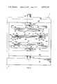
- FIG. 1is an over-all top plan view schematically illustrating a forming machine incorporating the invention
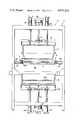
- FIG. 2is an elevational view taken along the lines 2--2 of FIG. 1, and showing the contact heating mechanism on an enlarged scale;
- FIG. 3is an elevational view taken along the lines 3--3 of FIG. 1 and showing, for purposes of illustration only, a forming station incorporating differential pressure forming molds;
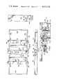
- FIG. 4is an enlarged plan view of one of the platens employed at the heating station, taken on the line 4--4 of FIG. 2, and with chain lines illustrating the position of the clamping bolts which are carried by one of the heater parts when the heater parts are in a normal or non-thermally expanded state;
- FIG. 5is an edge elevational view thereof
- FIG. 5ais a fragmentary, enlarged plan view of one of the platen mount plates, with chain lines illustrating the position of the clamping bolts which are carried by one of the heater parts when the heater parts are in a thermally expanded state;
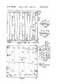
- FIG. 6is an enlarged, fragmentary, edge elevational view, with portions broken away to illustrate the manner of securing the contact heater parts together and to the platen which carries them;
- FIG. 7is a plan view of the heater carrier showing the heater strips position therein;
- FIG. 8is a fragmentary sectional view taken on the line 8--8 of FIG. 7;
- FIG. 9is a fragmentary cross-sectional view taken on the line 9--9 of FIG. 7;
- FIG. 10is a plan view illustrating the cover plate which mounts to the heater carrying plate illustrated in FIG. 7;
- FIG. 11is a fragmentary sectional view taken on the line 11--11 of FIG. 10;
- FIG. 12is a schematic electrical diagram illustrating the manner in which the contact heater mechanism may be controlled.
- a turntable Tfixed on a shaft 10 supported by a frame or framework F.
- the turntable Tmay include spokes 10a, which are fixed to a hub 10b which is keyed to the shaft 10, and the turntable T, as shown, is mounted for indexing rotary movements in the clockwise direction a.
- the frame Fprovides frame members which define various stations, at which the turntable T stops and dwells, to permit operations to be performed upon the sheets P which are carried by the turntable T.
- a loading-unloading station or locationmay comprise an unload station 11 and a load station 12, followed clockwisely by a heating station generally designated 13 and a forming station generally designated 14.
- a resistance type ribbon heating element assemblyis generally schematically shown at 15. It is to be understood that such are provided above and below the rotary path of four clamp frame assemblies, generally designated 16, which are revolved with the turntable T to indexed dwell positions at the various stations 11 through 14.
- the frame Fsupports upper and lower mold members 17 an 18, respectively (see FIG. 3) on platens 19 and 20, respectively, which may be operated by the piston rods 21 of conventional double acting, fluid pressure actuated upper and lower cylinders 22 and 23 mounted on the frame F.
- Stabilizer cylinders 24, which operate to continuously urge the platens 19 and 20 in a direction away from the path of travel of carriages 16are also provided and, of course, the pressure maintained in these is far less than the pressure utilized in cylinders 22 and 23 to move the platens 19 and 20 in a direction toward the path of travel of the carriages 16, and the sheets P which are carried thereby.
- the female mold 18is provided with suction ports 18a in the usual manner, connected to a suitable source of suction, such as a conventional suction pump, and the male member 17 operates as a conventional plug assist to move the heated sheets P into the mold 18 when the cylinders 22 and 23 are operated.
- a suitable source of suctionsuch as a conventional suction pump
- each sheet clamping frame assembly 16comprises an upper, rectangular frame member 25 which is fixed to the turntable structure T.
- Heat insulating pad members 25afor contacting the sheets P, are provided on the undersides of the framework members 25.
- Each pin 29also pivotally connects a link 32 to each piston rod 28, the opposite end of each link 32 being pivotally connected as at 33 to a link 34 which is pivotally connected at 35 to the turntable structure T.
- the link 34connects to the separable lower frame 36, which may be of similar rectangular form and is formed of four separate side rails 36a which may carry web penetrating pins (not shown) in the usual manner.
- the frame parts 36aare swung outwardly about pins 31, and at the same time are swung downwardly about pivot pins 35, until they reach withdrawn positions.
- several cylinders 27are provided on each separate side rail 36a of the frame 36 and that the separate side walls of the frame 36 are moved downwardly simultaneously when it is desired to remove the formed sheet P from the clamp frame assembly 16 at the unloading station 11.
- the present inventionis particularly concerned with the provision of a contact heater assembly both above and below the path of travel of carriages 16 and the individual plastic sheets P which are clamped therebetween (see FIG. 2).
- the heater mechanismincludes upper and lower resistance heater componentry which are of identical construction. Both such upper and lower assemblies includes a platen 37, connected with a piston rod 38 for movement toward and away from the path of travel of rotary carriages 16.
- the upper platen 37is operated by a double acting, fluid pressure operated cylinder 139, mounted to framework F, while the lower platen 37 is operated by a double acting fluid pressure operated cylinder 140, which is similarly mounted to the framework F.
- Framework Fas shown, may comprise a base part 141, side supports 142, top rails 143, and cross rails 144. Guides 145 for the piston rods 38 may be provided on the cross rails 144 as shown.
- each platen 37comprises a rectangular framework with longitudinally disposed rails 37a and connecting end rails 37b. Intermediate the ends of the framework platens 37 are cross pieces 39 supporting a central block 40 to which piston rod 38 attaches. Cross rails 41 also are provided to brace the framework structure 37.
- each platen 37Provided on the inner side of each platen 37, are a pair of centrally disposed mount plates or pads 42 which centrally align with the axis of piston rod 38 and the central axis of block 40.
- mount plates or bars 43Longitudinally or endwisely outboard of the block 40 and mount plates 42 are mount plates or bars 43, as shown particularly in FIG. 4. Openings 44, which are transversely or widthwisely elongate, are provided in mount plates 42 in alignment with the axis of piston rod 38 and the central axis of block 40.
- the plates 43carry elongate openings 45 which are longitudinally, or endwisely, elongate along an axis which is longitudinally aligned with the axis of piston rod 38 and the central axis of mount block 40.
- enlarged openings 46are also provided, for a purpose which will later also be explained.
- FIG. 6the left-hand plate 43 in FIG. 4 is pictured, whereas in FIG. 5a, the right-hand plate or bar 43 in FIG. 4 is illustrated. It is to be understood that the operation of each of these plates 43 in terms of their function to mount the carrier heater assemblies is identical.
- a heater carrierMounted to the plates 42 and 43 on each platen 37, in a manner which will now be described, is a heater carrier, generally designated 47 (see particularly FIG. 6), which includes a resistance heater element carrier plate 48, a cover plate 49, and a contact plate or adapter plate 50, each of which is formed of a highly heat conductive material, (which also is relatively thermally expansible) such as aluminum. It is possible that other materials, such as brass, may be used in place of the aluminum plates described. Thermal insulating side strips 50a surround the sides of the plates 50 so that each functions as a heat sink.
- each plate 48has parallel recesses 48a, to accommodate a series of parallel resistance heater ribbons 51 and, as shown, these recesses 48a are separated by integral ribs 52. Spanning the ends of the recesses 48a and the strip heaters 51 which are carried thereby, are recesses 53 which carry ribbon heater strip elements 54.
- the heater strips 51 and 54are commercially available from Watlow Electric Manufacturing of St. Louis, Missouri, and each include a pair of terminal posts 55 at one end, to which circuit wires may be connected.
- Eachincludes embedded resistance heating elements 56 (see FIG. 12), and each of the heating elements 51 and 54 are individually connected across a pair of power lines L1 and L2 in a circuit line such as shown at 57 in FIG. 12.
- Each circuit line 57may be broken by a control switch 58 so that any one of the heater elements 54 and 51 may be shut down while the others are operating, and a zoned heat control effected.
- a control switch 58so that any one of the heater elements 54 and 51 may be shut down while the others are operating, and a zoned heat control effected.
- a cover plate 49is fixed to the heater strip carrying plate 48 with its confronting surface in contact with the accessible surfaces of heater strips 51 and 54.
- the heater ribbons 51 and 54will be formed of stainless steel within which is a mica sheath housing a mica core around which the electrical resistance heater wires are wrapped. Since there will be a far greater turn, or coil, density throughout the body of heater strips 51 and 54 than at the extreme ends thereof where the resistance wire coils connect to terminals 55, the body of heaters 51 and 54 will be at a considerably greater temperature than will the end parts mounting terminals 55.
- the adjacent parallel heater strips 51are oppositely disposed in a manner such that their terminals 55 are alternately at opposite ends, and this arrangement is utilized in order to minimize the size of the relatively cold spots which occur at terminals 55 and to achieve a uniformity of heat distribution. It is for the same reason that heater strips 54 are provided to span the ends of the heater strips 51, and that the pairs of terminals 55 for each of the strips 54, are disposed at opposite ends of the carrier plate 48.
- openings 59to receive the terminal posts 55 and it will be seen that insulation covers 60 are provided for each of the terminal posts 55.
- steel bolts 61are threaded in the plates 48, extend through slightly enlarged openings 62 in the plates 49 and have back-to-back oppositely disposed disc spring washers, or belleville washers, 63 which are secured by a nut 64. Expansion of the plates 48 and 49 in the b direction, is permitted by the compressed washers 63 which can expand in the b direction.
- steel bolts 65 threaded into the contactor or adapter plate 50extend through openings 66 and 67, provided in the plates 49 and 48 respectively, and carry identical washers 68 which permit expansion of the plates 48 through 50 in the same b direction under the influence of higher termperature transfers.
- steel bolts 69extend through partly over-sized openings 70 and 71 provided in the plates 48 and 49 respectively, and up through enlarged openings 72 provided in the insulator strips 74 (i.e. asbestos) which thermally insulate the platen 37, and the openings 44 - 46 in mount plates 42 and 43.
- Identical spring washers 74apermit expansion of plates 48 and 49 in the b direction, and a nut 75 is utilized to rigidly secure the parts to platen parts 42 and 43.
- FIG. 4indicates the bolts or stud members 69, which are shown in chain lines in FIG. 4, are all carried by the aluminum plate assemblies, specifically plates 48, and are permitted to move with respect to openings 44, 45 and 46 which are of different shape according to their location to provide respectively for longitudinal or endwise expansion of the plates 48 through 50, transverse or widthwise expansion of the plates 48 through 50, and lateral expansion in directions therebetween.
- advance solenoids 76are provided for each of cylinders 139 and 140 to move the piston rods 38 is a direction toward the path of travel of carriages 16 and retract solenoids 77 are provided to restore them to the original spread-apart position, as shown in FIG. 2.
- the advance solenoids 76are under the control of a switch 78 which may be automatically operated when a carriage assembly 16 is moved to an indexed position between the platens 37 and halted.
- the retract solenoids 77are energized by a switch 79, operating under the influence of a conventional timer, started by a relay or contact switch when the platens 37 are moved to innermost position, and timing out after a "set" time when the sheets P have been heated to the desired forming temperature.
- a motor Mis provided to drive the turntable shaft via a suitable geneva mechanism or other drive which will index the turntable T during intervals separated by a period of dwell.
- the cylinders 139 and 140are operated to move the contactor plates 50 in a direction toward the sheet carrying carriage 16.
- the plates 50substantially come into contact with opposite sides of the sheet P, but never quite actually engage it. They are “set” to come into a position which may be ten thousandths of an inch removed from the surfaces of the sheets P, but this for practical purposes can be termed a "contacting", heat transfer relationship.
- the mechanismis set to operate in this manner to avoid compressing the sheet P. It is recognized that the under contactor plate 50 will, in fact, be engaged by, and support, the sheet P during the time the sheet is being heated to forming temperature.
- the identical heating stationmay be employed for heating the metallic alloy superplastic sheets to which reference has been made.
- the sheetswill be heated to a temperature, however, which approximates 500° F.
- FIG. 4indicates the position of the bolts 69, which rigidly secure the plates 48 through 50 to the platen 37. As the plates 48 through 50 are heated to operating temperature, the position of these bolts in openings 44, 45 and 46 changes in the matter indicated by the chain lines in FIG. 5a, as the plates 48 through 50 expand.
- the plate 49is spaced a given air distance x from the platen 37, and heat insulator pads 74 are provided under the mount members 42 and 43 to prevent heat transfer to the steel platen 37.
- the clamp frame parts 36 - 27, etc.,are protected by the insulating asbestos strips 50a which completely surround the contactor plate 50. These strips serve to hold in heat which would otherwise be lost by side radiation.
- retract solenoids 77are operated by the timer switch 79 to move the platens 37 apart to the withdrawn position shown in FIG. 2. After this, the carriage carrying the heated sheet P is indexed to the forming station 14, where a conventional forming operation is carried out, after which the formed sheet is indexed to the unload station 11.
Landscapes
- Engineering & Computer Science (AREA)
- Mechanical Engineering (AREA)
- Physics & Mathematics (AREA)
- Health & Medical Sciences (AREA)
- Oral & Maxillofacial Surgery (AREA)
- Thermal Sciences (AREA)
- Blow-Moulding Or Thermoforming Of Plastics Or The Like (AREA)
Abstract
Description
Differential pressure forming machinery for thermoplastic synthetic plastic sheets, and wherein the sheets are individually clamped in carriages and move in a continuous path from a loading station (where the sheets are individually loaded to a sheet clamping carriage), to a heating station (where the sheets are heated to a forming temperature at which they may be formed) to a forming or molding station (wherein the sheets are deformed by way of direct compression or differential pressure forces, or a combination of these, to the configuration of molds) and thence are indexed to an unloading station, and such machinery is disclosed for example in the present assignee's Brown Pat. No. 3,583,036. As this prior U.S. patent indicates, the heating station may be made up of two sets of upper and lower heating mechanisms arranged respectively above and below the path of travel of the sheets and a typical loading-unloading station may comprise a location at which the sheet which has been formed is unloaded and a circumferentially adjacent location at which a new sheet is reloaded. Differential pressure plastics forming machinery of this character conventionally employs radiant heaters which are located a predetermined distance away from the path of travel of the sheet at a heating station which may comprise one or more heating locations and sets of heaters, and normally the sheets sagged after being heated, as the heated portions became deformable and lost mechanical strength.
Recently, it has been determined that certain superplastic metal alloys can be formed much like plastics under very small forces and at temperatures in the neighborhood of 500° F. This property of superplasticity, which allows particular alloys such as zinc alloys (which may comprise 78% zinc and 22% aluminum) to be formed, is described in U.S. Pats. Nos. 3,340,101, 3,567,524, and 3,420,717. Forming processes for such superplastic alloys similarly include vacuum forming and compression forming.
One of the prime objects of the present invention is to provide contact heater mechanism which is particularly useful for heating certain thermoplastic synthetic plastics and superplastic metal alloys to a forming termperature. For example, it has been found that the apparatus which will be described transfers heat to the high moisture content plastic sheets or webs in a manner which does not cause the moisture to bubble out of the plastic or permit the plastic sheet to sag. Formerly, problems have been encountered with plastics such as certain polycarbonates and polystyrenes which attract moisture and build up a relatively high moisture content, and of course, sagging has traditionally been a well-recognized and accepted condition which is difficult to control. In present practice, separate ovens must operate at temperatures in the neighborhood of 1100° F. in order to accomplish pre-drying of such material before it is then cooled and loaded to conventional forming machinery wherein reheating occurs and forming is carried out at sheet-forming temperatures in the range of 280° - 320° F. This not only is costly in terms of power consumption, it also greatly increases fire hazards in the area of operation.
At the same time, it has been found that such contact heater mechanisms are extremely well suited to the heating of superplastic metallic alloys to forming temperatures in the neighborhood of 500° F., without creating sag or other problems.
It is a principal object of the present invention to provide highly reliable and efficient apparatus which is capable of use to heat both plastics and superplastic metals to forming temperatures in a manner which avoids many of the problems presently encountered with other heating methods.
Another important object of the invention is to provide mechanism which is constructed to permit thermal expansion of some of the parts relative to the others.
Still another object of the invention is to provide a construction employing a sandwiched heating mechanism wherein electrical resistance heating elements are enclosed within the confines of sandwiched heater plates mounting contactor plates which are moved toward and away from heat transfer relationship with the sheet to be heated to forming temperature.
Still another object of the invention is to provide a construction of the character mentioned wherein changeover costs are reduced and the contactor plates can be readily removed and changed to permit contactor plates of different size or shape to be mounted in position to heat sheets of varying size and shape.
Another object of the invention is to provide contact heater mechanism utilizing a multiplicity of electrical resistance heater elements which can be individually activated or deactivated to provide a zoned heat control which can selectively impart heat to particular areas of the contactor plates.
Another object of the invention is to provide contact heater apparatus of the character mentioned wherein strip heaters are employed, and in which they are arranged so that the creation of large cold spots is avoided.
Other objects and advantages of the invention will be pointed out specifically or will become apparent from the following description when it is considered in conjunction with the appended claims.
More particularly the invention is directed to a machine having upper and lower platens which are both moved toward and away from the path of travel of sheet-carrying carriages and the opposite sides of a sheet carried thereby. The platens each mount an electrical resistance heater carrier which includes a contactor plate, and each carrier is rigidly mounted on the platen in a manner to permit thermal expansion of the carrier with respect to the platen. The carrier is insulated from the platen in a manner to avoid as much heat transfer to the platen and other parts of the machine as possible.
FIG. 1 is an over-all top plan view schematically illustrating a forming machine incorporating the invention;
FIG. 2 is an elevational view taken along thelines 2--2 of FIG. 1, and showing the contact heating mechanism on an enlarged scale;
FIG. 3 is an elevational view taken along thelines 3--3 of FIG. 1 and showing, for purposes of illustration only, a forming station incorporating differential pressure forming molds;
FIG. 4 is an enlarged plan view of one of the platens employed at the heating station, taken on the line 4--4 of FIG. 2, and with chain lines illustrating the position of the clamping bolts which are carried by one of the heater parts when the heater parts are in a normal or non-thermally expanded state;
FIG. 5 is an edge elevational view thereof;
FIG. 5a is a fragmentary, enlarged plan view of one of the platen mount plates, with chain lines illustrating the position of the clamping bolts which are carried by one of the heater parts when the heater parts are in a thermally expanded state;
FIG. 6 is an enlarged, fragmentary, edge elevational view, with portions broken away to illustrate the manner of securing the contact heater parts together and to the platen which carries them;
FIG. 7 is a plan view of the heater carrier showing the heater strips position therein;
FIG. 8 is a fragmentary sectional view taken on theline 8--8 of FIG. 7;
FIG. 9 is a fragmentary cross-sectional view taken on the line 9--9 of FIG. 7;
FIG. 10 is a plan view illustrating the cover plate which mounts to the heater carrying plate illustrated in FIG. 7;
FIG. 11 is a fragmentary sectional view taken on the line 11--11 of FIG. 10; and
FIG. 12 is a schematic electrical diagram illustrating the manner in which the contact heater mechanism may be controlled.
Referring now more particularly to the accompanying drawings and in the first instance to FIG. 1, we have shown a turntable T fixed on ashaft 10 supported by a frame or framework F. The turntable T may includespokes 10a, which are fixed to a hub 10b which is keyed to theshaft 10, and the turntable T, as shown, is mounted for indexing rotary movements in the clockwise direction a. The frame F provides frame members which define various stations, at which the turntable T stops and dwells, to permit operations to be performed upon the sheets P which are carried by the turntable T. For example, a loading-unloading station or location, generally designated U-L, may comprise an unload station 11 and aload station 12, followed clockwisely by a heating station generally designated 13 and a forming station generally designated 14. At the heating station 13, a resistance type ribbon heating element assembly is generally schematically shown at 15. It is to be understood that such are provided above and below the rotary path of four clamp frame assemblies, generally designated 16, which are revolved with the turntable T to indexed dwell positions at the various stations 11 through 14.
At the formingstation 14, the frame F supports upper and lower mold members 17 an 18, respectively (see FIG. 3) onplatens piston rods 21 of conventional double acting, fluid pressure actuated upper andlower cylinders F. Stabilizer cylinders 24, which operate to continuously urge theplatens carriages 16 are also provided and, of course, the pressure maintained in these is far less than the pressure utilized incylinders platens carriages 16, and the sheets P which are carried thereby. Thefemale mold 18 is provided with suction ports 18a in the usual manner, connected to a suitable source of suction, such as a conventional suction pump, and the male member 17 operates as a conventional plug assist to move the heated sheets P into themold 18 when thecylinders
As shown particularly in FIGS. 2 and 3, each sheetclamping frame assembly 16 comprises an upper,rectangular frame member 25 which is fixed to the turntable structure T. Heat insulating pad members 25a, for contacting the sheets P, are provided on the undersides of theframework members 25. Mounted on each side of eachframe 25, aresupport brackets 26 for double acting, fluid pressure operatedcylinders 27 havingpiston rods 28 which are pivotally connected at 29 to operatng levers orlinks 30, which are pivotally connected at 31 to the turntable structure T. Eachpin 29 also pivotally connects alink 32 to eachpiston rod 28, the opposite end of eachlink 32 being pivotally connected as at 33 to alink 34 which is pivotally connected at 35 to the turntable structure T. Thelink 34 connects to the separablelower frame 36, which may be of similar rectangular form and is formed of fourseparate side rails 36a which may carry web penetrating pins (not shown) in the usual manner. When thepiston rods 28 are withdrawn or retracted, theframe parts 36a are swung outwardly aboutpins 31, and at the same time are swung downwardly aboutpivot pins 35, until they reach withdrawn positions. It is to be understood thatseveral cylinders 27 are provided on eachseparate side rail 36a of theframe 36 and that the separate side walls of theframe 36 are moved downwardly simultaneously when it is desired to remove the formed sheet P from theclamp frame assembly 16 at the unloading station 11.
As has been indicated, the present invention is particularly concerned with the provision of a contact heater assembly both above and below the path of travel ofcarriages 16 and the individual plastic sheets P which are clamped therebetween (see FIG. 2). At heating station 13, the heater mechanism includes upper and lower resistance heater componentry which are of identical construction. Both such upper and lower assemblies includes aplaten 37, connected with apiston rod 38 for movement toward and away from the path of travel ofrotary carriages 16. Theupper platen 37 is operated by a double acting, fluid pressure operatedcylinder 139, mounted to framework F, while thelower platen 37 is operated by a double acting fluid pressure operatedcylinder 140, which is similarly mounted to the framework F. Framework F, as shown, may comprise abase part 141, side supports 142,top rails 143, andcross rails 144.Guides 145 for thepiston rods 38 may be provided on thecross rails 144 as shown.
As FIGS. 4 and 5 illustrate, eachplaten 37 comprises a rectangular framework with longitudinally disposedrails 37a and connectingend rails 37b. Intermediate the ends of theframework platens 37 arecross pieces 39 supporting acentral block 40 to whichpiston rod 38 attaches.Cross rails 41 also are provided to brace theframework structure 37.
Provided on the inner side of eachplaten 37, are a pair of centrally disposed mount plates orpads 42 which centrally align with the axis ofpiston rod 38 and the central axis ofblock 40. Longitudinally or endwisely outboard of theblock 40 andmount plates 42 are mount plates orbars 43, as shown particularly in FIG. 4.Openings 44, which are transversely or widthwisely elongate, are provided inmount plates 42 in alignment with the axis ofpiston rod 38 and the central axis ofblock 40. Similarly, theplates 43 carryelongate openings 45 which are longitudinally, or endwisely, elongate along an axis which is longitudinally aligned with the axis ofpiston rod 38 and the central axis ofmount block 40. At the same time, at the ends ofplate 43,enlarged openings 46 are also provided, for a purpose which will later also be explained.
In FIG. 6, the left-hand plate 43 in FIG. 4 is pictured, whereas in FIG. 5a, the right-hand plate orbar 43 in FIG. 4 is illustrated. It is to be understood that the operation of each of theseplates 43 in terms of their function to mount the carrier heater assemblies is identical.
Mounted to theplates platen 37, in a manner which will now be described, is a heater carrier, generally designated 47 (see particularly FIG. 6), which includes a resistance heaterelement carrier plate 48, acover plate 49, and a contact plate oradapter plate 50, each of which is formed of a highly heat conductive material, (which also is relatively thermally expansible) such as aluminum. It is possible that other materials, such as brass, may be used in place of the aluminum plates described. Thermal insulating side strips 50a surround the sides of theplates 50 so that each functions as a heat sink.
As FIGS. 7 through 9 particularly indicate, eachplate 48 hasparallel recesses 48a, to accommodate a series of parallelresistance heater ribbons 51 and, as shown, theserecesses 48a are separated byintegral ribs 52. Spanning the ends of therecesses 48a and thestrip heaters 51 which are carried thereby, arerecesses 53 which carry ribbonheater strip elements 54. The heater strips 51 and 54 are commercially available from Watlow Electric Manufacturing of St. Louis, Missouri, and each include a pair ofterminal posts 55 at one end, to which circuit wires may be connected. Each includes embedded resistance heating elements 56 (see FIG. 12), and each of theheating elements circuit line 57 may be broken by acontrol switch 58 so that any one of theheater elements element
As FIGS. 8 and 9 particularly indicate, acover plate 49 is fixed to the heaterstrip carrying plate 48 with its confronting surface in contact with the accessible surfaces of heater strips 51 and 54. Typically, theheater ribbons terminals 55, the body ofheaters parts mounting terminals 55. For this reason, the adjacent parallel heater strips 51 are oppositely disposed in a manner such that theirterminals 55 are alternately at opposite ends, and this arrangement is utilized in order to minimize the size of the relatively cold spots which occur atterminals 55 and to achieve a uniformity of heat distribution. It is for the same reason that heater strips 54 are provided to span the ends of the heater strips 51, and that the pairs ofterminals 55 for each of thestrips 54, are disposed at opposite ends of thecarrier plate 48.
Provided in theplate 49 areopenings 59 to receive the terminal posts 55 and it will be seen that insulation covers 60 are provided for each of the terminal posts 55. To connect theplates steel bolts 61 are threaded in theplates 48, extend through slightlyenlarged openings 62 in theplates 49 and have back-to-back oppositely disposed disc spring washers, or belleville washers, 63 which are secured by anut 64. Expansion of theplates compressed washers 63 which can expand in the b direction. Similarly,steel bolts 65 threaded into the contactor oradapter plate 50 extend throughopenings plates identical washers 68 which permit expansion of theplates 48 through 50 in the same b direction under the influence of higher termperature transfers. Finally,steel bolts 69 extend through partlyover-sized openings plates platen 37, and the openings 44 - 46 inmount plates plates nut 75 is utilized to rigidly secure the parts to platenparts
As FIG. 4 indicates the bolts orstud members 69, which are shown in chain lines in FIG. 4, are all carried by the aluminum plate assemblies, specificallyplates 48, and are permitted to move with respect toopenings plates 48 through 50, transverse or widthwise expansion of theplates 48 through 50, and lateral expansion in directions therebetween.
As FIG. 12 indicates, advancesolenoids 76 are provided for each ofcylinders piston rods 38 is a direction toward the path of travel ofcarriages 16 and retract solenoids 77 are provided to restore them to the original spread-apart position, as shown in FIG. 2. The advance solenoids 76 are under the control of a switch 78 which may be automatically operated when acarriage assembly 16 is moved to an indexed position between theplatens 37 and halted. The retract solenoids 77 are energized by aswitch 79, operating under the influence of a conventional timer, started by a relay or contact switch when theplatens 37 are moved to innermost position, and timing out after a "set" time when the sheets P have been heated to the desired forming temperature. A motor M is provided to drive the turntable shaft via a suitable geneva mechanism or other drive which will index the turntable T during intervals separated by a period of dwell.
An operator at the loading and unloading station U-L, and after unloading a previously formed sheet at station 11, will reload theclamp frame assembly 16 atstation 12 by inserting a new sheet therein. To do this it is, of course, necessary to, at station 11, actuate thecylinders 27 to swing theparts 36a ofclamp frame 36 downwardly and outwardly. At theloading assembly 12, with sheets being moved upwardly to a position against clamp frame surfaces 25a,cylinders 27 will then be operated in the reverse direction to swing theclamp plate parts 36a back to the position in which they are shown in FIG. 2. At this time, the loaded clamp frame is indexed to the position shown in FIG. 2 in which it is disposed between the retractedplatens 37.
With operation of the switch 78, thecylinders contactor plates 50 in a direction toward thesheet carrying carriage 16. It is to be understood that theplates 50 substantially come into contact with opposite sides of the sheet P, but never quite actually engage it. They are "set" to come into a position which may be ten thousandths of an inch removed from the surfaces of the sheets P, but this for practical purposes can be termed a "contacting", heat transfer relationship. The mechanism is set to operate in this manner to avoid compressing the sheet P. It is recognized that the undercontactor plate 50 will, in fact, be engaged by, and support, the sheet P during the time the sheet is being heated to forming temperature.
While we have particularly described an apparatus for forming plastic sheets, it should be understood that the identical heating station may be employed for heating the metallic alloy superplastic sheets to which reference has been made. In this case, the sheets will be heated to a temperature, however, which approximates 500° F.
Unless some zoned heat control is desired, the heater strips 51 and 54 will be continuously energized, and theplates 48 through 50 will be maintained in a constant "hot" condition at a uniform temperature. At start-up, FIG. 4 indicates the position of thebolts 69, which rigidly secure theplates 48 through 50 to theplaten 37. As theplates 48 through 50 are heated to operating temperature, the position of these bolts inopenings plates 48 through 50 expand.
As FIG. 6 particularly indicates, theplate 49 is spaced a given air distance x from theplaten 37, andheat insulator pads 74 are provided under themount members steel platen 37. The clamp frame parts 36 - 27, etc., are protected by the insulating asbestos strips 50a which completely surround thecontactor plate 50. These strips serve to hold in heat which would otherwise be lost by side radiation.
Once the sheets P have been heated to the desired forming temperature, retract solenoids 77 are operated by thetimer switch 79 to move theplatens 37 apart to the withdrawn position shown in FIG. 2. After this, the carriage carrying the heated sheet P is indexed to the formingstation 14, where a conventional forming operation is carried out, after which the formed sheet is indexed to the unload station 11.
It is to be understood that the drawings and descriptive matter are in all cases to be interpreted as merely illustrative of the principles of the invention, rather than as limiting the same in any way, since it is contemplated that various changes may be made in various elements to achieve like results without departing from the spirit of the invention or the scope of the appended claims.
Claims (7)
1. In differential pressure forming appartus including a contact heater mechanism for contact heating heat deformable sheet stock to a predetermined temperature a generally flat heater assembly having a central axis normal to the general plane of said heater assembly, the improvement comprising: a carrier assembly having a central axis coincident with said central axis of said heater assembly; a plurality of fastener members mounted on one assembly received in a plurality of fastener receiving openings in the other of said assemblies to mount the heater assembly upon the carrier assembly; means for moving the carrier assembly to and from a work heating station; a first pair of said openings being symmetrically spread on opposite sides of said central axis, said first pair of said openings being elongated in an x direction parallel to a direct line connecting said openings and intersecting said central axis to accommodate thermal expansion of said heater assembly relative to said carrier assembly in said x direction, a second pair of said openings being symmetrically spaced on opposite sides of said central axis and being elongated in a y direction, normal to said x direction, to accommodate thermal expansion of said heater assembly relative to said carrier assembly in said y direction, said first and second pair of openings accommodating the aforementioned thermal expansion of said heater assembly relative to said carrier assembly while maintaining said central axes of said heater assembly and carrier assembly in coincidence with each other.
2. The invention defined in claim 1 wherein said heater assembly is of a generally flat rectangular configuration and said plurality of openings further comprises third and fourth pairs of openings symmetrically spaced on opposite sides of said central axis and with respect to said first and said second pairs of openings, said third and fourth pairs of openings being of enlarged circular configuration to accommodate thermal expansion of said heater assembly in any direction in said general plane.
3. The invention defined in claim 1 wherein said fastener means comprises bolt means accommodating thermal expansion of said heater assembly relative to said carrier in a z direction mutually perpendicular to said x and said y directions.
4. In differential pressure forming apparatus including a contact heater mechanism for contact heating heat deformable sheet stock to a predetermined temperature, having a frame, reciprocatory ram means mounted upon said frame, a platen mounted on said ram means for movement therewith, a generally flat rectangular contact heating assembly, the improvement comprising: means mounting said heating assembly in spaced thermally insulated relationship to said platen comprising thermal insulating means disposed between said heater assembly and said platen, a plurality of elongate fastener elements projecting from one side of said heater assembly through respective aligned fastener receiving openings in said pad means and said platen to mount said heater assembly on said platen with said pad means clamped therebetween, said heater assembly being symmetrically disposed to the axis of said ram means and lying in a general plane normal to said axis, a plurality of pairs of said fastener receiving openings being symmetrically located on opposite sides of said axis and elongated in directions extending radially from said axis to accommodate thermal expansion of said heater assembly in said general plane while maintaining said heater assembly in its symmetrical disposition relative to said axis.
5. The invention defined in claim 4 wherein said heater assembly comprises a rectangular contact plate mounted on the side of said heater assembly remote from said platen, and thermal insulation means mounted upon the peripheral side edges of said contact plate.
6. The invention defined in claim 5 wherein said plurality of pairs of openings comprise a first pair of openings located on the transverse centerline of said rectangular heater assembly and a second pair of openings located on the longitudinal centerline of said rectangular heater assembly, said transverse and longitudinal centerlines intersecting each other at said axis, and four additional fastener receiving openings located at the respective corners of a rectangle having said first and second pairs of openings located at the midpoint of each of its sides, said four additional openings being constituted by circular bores of a diameter substantially exceeding that of said fastener means.
7. The invention defined in claim 6 further comprising means in said fastener means accommodating thermal expansion of said heater assembly in a direction parallel to said axis.
Priority Applications (1)
| Application Number | Priority Date | Filing Date | Title |
|---|---|---|---|
| US05/616,408US4079232A (en) | 1975-09-24 | 1975-09-24 | Contact heater mechanisms for thermoforming machines |
Applications Claiming Priority (1)
| Application Number | Priority Date | Filing Date | Title |
|---|---|---|---|
| US05/616,408US4079232A (en) | 1975-09-24 | 1975-09-24 | Contact heater mechanisms for thermoforming machines |
Publications (1)
| Publication Number | Publication Date |
|---|---|
| US4079232Atrue US4079232A (en) | 1978-03-14 |
Family
ID=24469329
Family Applications (1)
| Application Number | Title | Priority Date | Filing Date |
|---|---|---|---|
| US05/616,408Expired - LifetimeUS4079232A (en) | 1975-09-24 | 1975-09-24 | Contact heater mechanisms for thermoforming machines |
Country Status (1)
| Country | Link |
|---|---|
| US (1) | US4079232A (en) |
Cited By (24)
| Publication number | Priority date | Publication date | Assignee | Title |
|---|---|---|---|---|
| FR2570643A1 (en)* | 1984-09-25 | 1986-03-28 | Multivac Haggenmueller Kg | DEVICE FOR HEATING A SHEET BEFORE DEFORMATION |
| EP0191898A1 (en)* | 1984-10-05 | 1986-08-27 | Multivac Sepp Haggenmüller Kg | Device for heating a sheet prior to its shaping |
| WO1989011962A1 (en)* | 1988-06-04 | 1989-12-14 | Basildon Moulding Company Limited | Plastics moulding apparatus |
| WO1995033617A1 (en)* | 1994-06-06 | 1995-12-14 | Tetra Laval Holdings & Finance S.A. | A device for heating tools in thermoforming |
| FR2737285A1 (en)* | 1995-07-28 | 1997-01-31 | Martinez Hubert | Industrial electric resistance oven or furnace for heat-deformable plastic plates - has upper and lower hinged insulated slabs having electrically heated sole-plates, with closely adjustable separation |
| US5620715A (en)* | 1994-02-10 | 1997-04-15 | Penda Corporation | Thermoforming machine with controlled cooling station |
| US6294114B1 (en) | 1998-08-20 | 2001-09-25 | Scott A. W. Muirhead | Triple sheet thermoforming apparatus, methods and articles |
| US6661339B2 (en) | 2000-01-24 | 2003-12-09 | Nextreme, L.L.C. | High performance fuel tank |
| US6749418B2 (en) | 1998-08-20 | 2004-06-15 | Scott A. W. Muirhead | Triple sheet thermoforming apparatus |
| US20040118488A1 (en)* | 2002-12-18 | 2004-06-24 | Carsley John E. | Heating of metal alloy sheet by thermal conduction |
| US6943678B2 (en) | 2000-01-24 | 2005-09-13 | Nextreme, L.L.C. | Thermoformed apparatus having a communications device |
| US20060006580A1 (en)* | 2002-08-27 | 2006-01-12 | Obducat Ab | Device for transferring a pattern to an object |
| US20060237420A1 (en)* | 2004-11-30 | 2006-10-26 | Peter Friedman | Apparatus and method for heating and transferring a workpiece prior to forming |
| US20070145039A1 (en)* | 2005-12-23 | 2007-06-28 | Donald Nevin | Internal heater for thermoform plastic sheet |
| US20070171080A1 (en)* | 2000-01-24 | 2007-07-26 | Scott Muirhead | Material handling apparatus with a cellular communications device |
| US20080122610A1 (en)* | 2000-01-24 | 2008-05-29 | Nextreme L.L.C. | RF-enabled pallet |
| US20100192659A1 (en)* | 2009-02-05 | 2010-08-05 | Paul Edward Krajewski | Elevated temperature forming method and preheater apparatus |
| CN104723545A (en)* | 2015-02-13 | 2015-06-24 | 潍坊世纪元通工贸有限公司 | Multifunctional forming machine |
| US20160136712A1 (en)* | 2013-06-05 | 2016-05-19 | Neturen Co., Ltd. | Heating method, heating apparatus, and hot press molding method for plate workpiece |
| US20180207792A1 (en)* | 2015-07-22 | 2018-07-26 | Fibro Lapple Technology GmbH | High-speed gantry system having a linear drive |
| US10071523B2 (en)* | 2014-04-25 | 2018-09-11 | William C. Shanley, Iv | Apparatus and methods for controlling pressure on a thermoforming assistive device |
| US20230140091A1 (en)* | 2021-11-03 | 2023-05-04 | Safe Life Defense, Llc | Ammunition magazine pouch and methods of assembling same |
| CN117232349A (en)* | 2023-10-06 | 2023-12-15 | 中国人民解放军陆军工程大学 | Control system for signal marking |
| US11845234B2 (en) | 2019-01-25 | 2023-12-19 | National Research Council Of Canada | Articulated forming caul for composite blank vacuum forming |
Citations (7)
| Publication number | Priority date | Publication date | Assignee | Title |
|---|---|---|---|---|
| US3045098A (en)* | 1959-11-19 | 1962-07-17 | Thermel Inc | Electric heater |
| US3269885A (en)* | 1963-09-25 | 1966-08-30 | Packaging Frontiers Inc | Heat-sealing head |
| US3478192A (en)* | 1968-04-25 | 1969-11-11 | Ostrander Seymour Co | Electrically heated platen |
| US3583036A (en)* | 1969-04-07 | 1971-06-08 | Koehring Co | Double web differential forming apparatus |
| US3859159A (en)* | 1971-12-03 | 1975-01-07 | Du Pont | Apparatus for forming a rupturable seal |
| US3868209A (en)* | 1973-02-22 | 1975-02-25 | Koehring Co | Twin sheet thermoformer |
| US3888719A (en)* | 1973-04-10 | 1975-06-10 | Seal | Adjustable vacuum press |
- 1975
- 1975-09-24USUS05/616,408patent/US4079232A/ennot_activeExpired - Lifetime
Patent Citations (7)
| Publication number | Priority date | Publication date | Assignee | Title |
|---|---|---|---|---|
| US3045098A (en)* | 1959-11-19 | 1962-07-17 | Thermel Inc | Electric heater |
| US3269885A (en)* | 1963-09-25 | 1966-08-30 | Packaging Frontiers Inc | Heat-sealing head |
| US3478192A (en)* | 1968-04-25 | 1969-11-11 | Ostrander Seymour Co | Electrically heated platen |
| US3583036A (en)* | 1969-04-07 | 1971-06-08 | Koehring Co | Double web differential forming apparatus |
| US3859159A (en)* | 1971-12-03 | 1975-01-07 | Du Pont | Apparatus for forming a rupturable seal |
| US3868209A (en)* | 1973-02-22 | 1975-02-25 | Koehring Co | Twin sheet thermoformer |
| US3888719A (en)* | 1973-04-10 | 1975-06-10 | Seal | Adjustable vacuum press |
Cited By (41)
| Publication number | Priority date | Publication date | Assignee | Title |
|---|---|---|---|---|
| FR2570643A1 (en)* | 1984-09-25 | 1986-03-28 | Multivac Haggenmueller Kg | DEVICE FOR HEATING A SHEET BEFORE DEFORMATION |
| EP0191898A1 (en)* | 1984-10-05 | 1986-08-27 | Multivac Sepp Haggenmüller Kg | Device for heating a sheet prior to its shaping |
| WO1989011962A1 (en)* | 1988-06-04 | 1989-12-14 | Basildon Moulding Company Limited | Plastics moulding apparatus |
| US5620715A (en)* | 1994-02-10 | 1997-04-15 | Penda Corporation | Thermoforming machine with controlled cooling station |
| WO1995033617A1 (en)* | 1994-06-06 | 1995-12-14 | Tetra Laval Holdings & Finance S.A. | A device for heating tools in thermoforming |
| FR2737285A1 (en)* | 1995-07-28 | 1997-01-31 | Martinez Hubert | Industrial electric resistance oven or furnace for heat-deformable plastic plates - has upper and lower hinged insulated slabs having electrically heated sole-plates, with closely adjustable separation |
| US6749418B2 (en) | 1998-08-20 | 2004-06-15 | Scott A. W. Muirhead | Triple sheet thermoforming apparatus |
| US6294114B1 (en) | 1998-08-20 | 2001-09-25 | Scott A. W. Muirhead | Triple sheet thermoforming apparatus, methods and articles |
| US7948371B2 (en) | 2000-01-24 | 2011-05-24 | Nextreme Llc | Material handling apparatus with a cellular communications device |
| US20070171080A1 (en)* | 2000-01-24 | 2007-07-26 | Scott Muirhead | Material handling apparatus with a cellular communications device |
| US6661339B2 (en) | 2000-01-24 | 2003-12-09 | Nextreme, L.L.C. | High performance fuel tank |
| US6943678B2 (en) | 2000-01-24 | 2005-09-13 | Nextreme, L.L.C. | Thermoformed apparatus having a communications device |
| US7752980B2 (en) | 2000-01-24 | 2010-07-13 | Nextreme Llc | Material handling apparatus having a reader/writer |
| US8585850B2 (en) | 2000-01-24 | 2013-11-19 | Nextreme, Llc | Thermoformed platform having a communications device |
| US20060243174A1 (en)* | 2000-01-24 | 2006-11-02 | Nextreme, L.L.C. | Thermoformed platform having a communications device |
| US8077040B2 (en) | 2000-01-24 | 2011-12-13 | Nextreme, Llc | RF-enabled pallet |
| US7804400B2 (en) | 2000-01-24 | 2010-09-28 | Nextreme, Llc | Thermoformed platform having a communications device |
| US20070163472A1 (en)* | 2000-01-24 | 2007-07-19 | Scott Muirhead | Material handling apparatus having a reader/writer |
| US9230227B2 (en) | 2000-01-24 | 2016-01-05 | Nextreme, Llc | Pallet |
| US20080122610A1 (en)* | 2000-01-24 | 2008-05-29 | Nextreme L.L.C. | RF-enabled pallet |
| US20080121339A1 (en)* | 2000-01-24 | 2008-05-29 | Nextreme L.L.C. | Thermoformed platform having a communications device |
| US7754131B2 (en)* | 2002-08-27 | 2010-07-13 | Obducat Ab | Device for transferring a pattern to an object |
| US20060006580A1 (en)* | 2002-08-27 | 2006-01-12 | Obducat Ab | Device for transferring a pattern to an object |
| US6890394B2 (en)* | 2002-12-18 | 2005-05-10 | General Motors Corporation | Heating of metal alloy sheet by thermal conduction |
| US20040118488A1 (en)* | 2002-12-18 | 2004-06-24 | Carsley John E. | Heating of metal alloy sheet by thermal conduction |
| US7199334B2 (en)* | 2004-11-30 | 2007-04-03 | Ford Global Technologies, Llc. | Apparatus and method for heating and transferring a workpiece prior to forming |
| US20060237420A1 (en)* | 2004-11-30 | 2006-10-26 | Peter Friedman | Apparatus and method for heating and transferring a workpiece prior to forming |
| US20070145039A1 (en)* | 2005-12-23 | 2007-06-28 | Donald Nevin | Internal heater for thermoform plastic sheet |
| US8017891B2 (en) | 2005-12-23 | 2011-09-13 | Donald Nevin | Internal heater for thermoform plastic sheet |
| US8459084B2 (en)* | 2009-02-05 | 2013-06-11 | Usamp | Elevated temperature forming method and preheater apparatus |
| US20100192659A1 (en)* | 2009-02-05 | 2010-08-05 | Paul Edward Krajewski | Elevated temperature forming method and preheater apparatus |
| US20160136712A1 (en)* | 2013-06-05 | 2016-05-19 | Neturen Co., Ltd. | Heating method, heating apparatus, and hot press molding method for plate workpiece |
| US20190030584A1 (en)* | 2013-06-05 | 2019-01-31 | Neturen Co., Ltd. | Heating method, heating apparatus, and hot press molding method for plate workpiece |
| US10071523B2 (en)* | 2014-04-25 | 2018-09-11 | William C. Shanley, Iv | Apparatus and methods for controlling pressure on a thermoforming assistive device |
| CN104723545A (en)* | 2015-02-13 | 2015-06-24 | 潍坊世纪元通工贸有限公司 | Multifunctional forming machine |
| US20180207792A1 (en)* | 2015-07-22 | 2018-07-26 | Fibro Lapple Technology GmbH | High-speed gantry system having a linear drive |
| US11845234B2 (en) | 2019-01-25 | 2023-12-19 | National Research Council Of Canada | Articulated forming caul for composite blank vacuum forming |
| US20230140091A1 (en)* | 2021-11-03 | 2023-05-04 | Safe Life Defense, Llc | Ammunition magazine pouch and methods of assembling same |
| US12339110B2 (en)* | 2021-11-03 | 2025-06-24 | Safe Life Defense, L.L.C. | Ammunition magazine pouch and methods of assembling same |
| US12410997B2 (en) | 2021-11-03 | 2025-09-09 | Safe Life Defense, L.L.C. | Ammunition magazine pouch and methods of assembling same |
| CN117232349A (en)* | 2023-10-06 | 2023-12-15 | 中国人民解放军陆军工程大学 | Control system for signal marking |
Similar Documents
| Publication | Publication Date | Title |
|---|---|---|
| US4079232A (en) | Contact heater mechanisms for thermoforming machines | |
| US3802974A (en) | Method and apparatus for insulating electrically conductive elements | |
| US3835282A (en) | Induction heating apparatus for heating the marginal edge of a disk | |
| US4268238A (en) | Flow molding | |
| US5082436A (en) | Apparatus for deforming thermoplastic material using RF heating | |
| US3779687A (en) | Apparatus of vacuum forming | |
| EP1024941B1 (en) | Apparatus and method for blow moulding two thermoplastic sheets with the use of pneumatic operable membranes which close the mould halfs | |
| US11298739B2 (en) | Method for manufacturing iron core | |
| US5290490A (en) | Method and apparatus for differentially heating and thermoforming a polymer sheet | |
| US4659304A (en) | Molding | |
| US4370188A (en) | Method and apparatus for insulating coils for rotary electric machines | |
| US3614383A (en) | Impulse heating device for use with thermoplastic materials and method | |
| US6322651B1 (en) | Method for continuously producing expanded thermoformable materials | |
| US2276380A (en) | Electric blasting initiator | |
| US3951713A (en) | Method and apparatus for insulating electrically conductive elements | |
| US3938931A (en) | Apparatus for insulating electrically conductive elements | |
| KR102128500B1 (en) | method of hot press forming using electrically assisted heater | |
| US1321517A (en) | House electric | |
| EP0190810A1 (en) | A method of joining plastic pipe ends and a connector sleeve for use therewith | |
| US3185073A (en) | Apparatus for preventing belt distortion | |
| US3268218A (en) | Heat treating induction coil | |
| US3151591A (en) | Heat bonding apparatus | |
| US3039139A (en) | Apparatus for manufacture of phonograph records | |
| US1669005A (en) | Heating element for tempering machines | |
| US3840423A (en) | Apparatus for bonding heat-exchanger components |
Legal Events
| Date | Code | Title | Description |
|---|---|---|---|
| AS | Assignment | Owner name:JOHN BROWN INDUSTRIES LTD.; 100 WEST TENTH ST., WI Free format text:ASSIGNMENT OF ASSIGNORS INTEREST.;ASSIGNOR:LEESONA CORPORATION; 333 STRAWBERRY FIELD RD., WARWICK, RI. A CORP. OF MA.;REEL/FRAME:003936/0206 Effective date:19810501 | |
| AS | Assignment | Owner name:LEESONA CORPORATION Free format text:CHANGE OF NAME;ASSIGNOR:JOHN BROWN INDUSTRIES LTD.;REEL/FRAME:003936/0238 Effective date:19810331 | |
| AS | Assignment | Owner name:LEESONA CORPORATION, A CORP. OF MASS. Free format text:ASSIGNMENT OF ASSIGNORS INTEREST.;ASSIGNOR:KOEHRING COMPANY;REEL/FRAME:003954/0491 Effective date:19751212 Owner name:LEESONA CORPORATION, A CORP. OF MASS., MASSACHUSET Free format text:ASSIGNMENT OF ASSIGNORS INTEREST;ASSIGNOR:KOEHRING COMPANY;REEL/FRAME:003954/0491 Effective date:19751212 |