US4077429A - Push-fit inlet valve assembly - Google Patents
Push-fit inlet valve assemblyDownload PDFInfo
- Publication number
- US4077429A US4077429AUS05/754,037US75403776AUS4077429AUS 4077429 AUS4077429 AUS 4077429AUS 75403776 AUS75403776 AUS 75403776AUS 4077429 AUS4077429 AUS 4077429A
- Authority
- US
- United States
- Prior art keywords
- valve member
- stem
- bore
- protuberance
- extending
- Prior art date
- Legal status (The legal status is an assumption and is not a legal conclusion. Google has not performed a legal analysis and makes no representation as to the accuracy of the status listed.)
- Expired - Lifetime
Links
- 238000007789sealingMethods0.000claimsabstractdescription10
- 230000004323axial lengthEffects0.000claimsdescription13
- 239000000463materialSubstances0.000claimsdescription10
- 229910001369BrassInorganic materials0.000claimsdescription3
- 239000010951brassSubstances0.000claimsdescription3
- 239000001273butaneSubstances0.000claimsdescription3
- 239000013536elastomeric materialSubstances0.000claimsdescription3
- 239000012530fluidSubstances0.000claimsdescription3
- IJDNQMDRQITEOD-UHFFFAOYSA-Nn-butaneChemical compoundCCCCIJDNQMDRQITEOD-UHFFFAOYSA-N0.000claimsdescription3
- OFBQJSOFQDEBGM-UHFFFAOYSA-Nn-pentaneNatural productsCCCCCOFBQJSOFQDEBGM-UHFFFAOYSA-N0.000claimsdescription3
- HCHKCACWOHOZIP-UHFFFAOYSA-NZincChemical compound[Zn]HCHKCACWOHOZIP-UHFFFAOYSA-N0.000claimsdescription2
- 238000004512die castingMethods0.000claimsdescription2
- 229910052725zincInorganic materials0.000claimsdescription2
- 239000011701zincSubstances0.000claimsdescription2
- 239000000446fuelSubstances0.000abstractdescription33
- 230000000694effectsEffects0.000abstractdescription2
- 239000007789gasSubstances0.000description5
- 239000003915liquefied petroleum gasSubstances0.000description4
- 239000007788liquidSubstances0.000description2
- 239000007921spraySubstances0.000description2
- 230000000903blocking effectEffects0.000description1
- 230000000881depressing effectEffects0.000description1
- 230000000994depressogenic effectEffects0.000description1
- 238000006073displacement reactionMethods0.000description1
- 239000002184metalSubstances0.000description1
- 229910052751metalInorganic materials0.000description1
- 150000002825nitrilesChemical class0.000description1
- 230000011664signalingEffects0.000description1
Images


Classifications
- F—MECHANICAL ENGINEERING; LIGHTING; HEATING; WEAPONS; BLASTING
- F16—ENGINEERING ELEMENTS AND UNITS; GENERAL MEASURES FOR PRODUCING AND MAINTAINING EFFECTIVE FUNCTIONING OF MACHINES OR INSTALLATIONS; THERMAL INSULATION IN GENERAL
- F16K—VALVES; TAPS; COCKS; ACTUATING-FLOATS; DEVICES FOR VENTING OR AERATING
- F16K24/00—Devices, e.g. valves, for venting or aerating enclosures
- F—MECHANICAL ENGINEERING; LIGHTING; HEATING; WEAPONS; BLASTING
- F23—COMBUSTION APPARATUS; COMBUSTION PROCESSES
- F23Q—IGNITION; EXTINGUISHING-DEVICES
- F23Q2/00—Lighters containing fuel, e.g. for cigarettes
- F23Q2/34—Component parts or accessories
- F23Q2/52—Filling devices
- Y—GENERAL TAGGING OF NEW TECHNOLOGICAL DEVELOPMENTS; GENERAL TAGGING OF CROSS-SECTIONAL TECHNOLOGIES SPANNING OVER SEVERAL SECTIONS OF THE IPC; TECHNICAL SUBJECTS COVERED BY FORMER USPC CROSS-REFERENCE ART COLLECTIONS [XRACs] AND DIGESTS
- Y10—TECHNICAL SUBJECTS COVERED BY FORMER USPC
- Y10T—TECHNICAL SUBJECTS COVERED BY FORMER US CLASSIFICATION
- Y10T137/00—Fluid handling
- Y10T137/7722—Line condition change responsive valves
- Y10T137/7837—Direct response valves [i.e., check valve type]
- Y10T137/7879—Resilient material valve
- Y10T137/788—Having expansible port
- Y10T137/7882—Having exit lip
- Y—GENERAL TAGGING OF NEW TECHNOLOGICAL DEVELOPMENTS; GENERAL TAGGING OF CROSS-SECTIONAL TECHNOLOGIES SPANNING OVER SEVERAL SECTIONS OF THE IPC; TECHNICAL SUBJECTS COVERED BY FORMER USPC CROSS-REFERENCE ART COLLECTIONS [XRACs] AND DIGESTS
- Y10—TECHNICAL SUBJECTS COVERED BY FORMER USPC
- Y10T—TECHNICAL SUBJECTS COVERED BY FORMER US CLASSIFICATION
- Y10T137/00—Fluid handling
- Y10T137/8593—Systems
- Y10T137/86292—System with plural openings, one a gas vent or access opening
- Y10T137/86324—Tank with gas vent and inlet or outlet
- Y10T137/86332—Vent and inlet or outlet in unitary mounting
Definitions
- the present inventionis directed to a valve closure for a fuel chamber such as in a gas lighter using a liquid petroleum gas and, more particularly, it is directed to a two-part push-fit inlet valve assembly.
- Inlet valves for gas lighters and similar applicationsare known, however, they generally require a number of parts including metal parts produced on screw machines or eyelet machines, coil springs, gaskets, and O-rings for effecting the desired sealing or closing action.
- the variety of parts usedrenders the valves relatively costly.
- the partsmust be assembled using highly complex equipment before the valve can be placed in the lighter and such assembly increases the cost.
- the expense of installing the valveis further increased by the need for threading the member into which the valve is secured.
- Another object of the inventionis to provide an inlet valve assembly which is easily operable, assures rapid filling of the fuel chamber, and provides a signal when the proper amount of fuel has been supplied into the chamber.
- the inlet valve assemblyconsists of two simple parts, a flexible valve member and a rigid stem which fits into a bore in the valve member.
- the valve memberis shaped to provide tightly fitting engagement with the wall forming the opening into the fuel chamber so that it provides a seal against any leakage of fuel out of the chamber.
- the stemextends through the bore in the valve member and assists in holding it in tightly fitting engagement with the opening.
- the end of the bore in the valve memberterminates in a slit which is normally closed.
- the outer surface of the valve member which seats against the axially extending surface of the openinghas a groove extending in the axial direction which is closed to the interior of the fuel chamber when the valve member is in its normal sealing position.
- a refill containeris pressed against the stem and, in turn, the stem is pressed inwardly causing the flexible valve member to project into the fuel chamber so that its seal with the inner surface of the chamber is broken. While the outer surface of the valve member still remains in surface contact with the opening, the groove in the outer surface is placed in communication with the interior of the chamber and, since the groove extends outwardly into communication with the ambient atmosphere, the interior of the chamber is exposed to atmospheric pressure.
- further inward movement of the refill container against the stemsupplies the liquid petroleum gas through a bore in the stem into the bore in the valve member and the pressure differential between the gas and the atmospheric pressure within the chamber opens the slit with the gas flowing into the chamber.
- a liquid sprayis forced out along an exhaust path through the groove in the outer surface of the valve member providing a signal that the filling operation should be stopped.
- the refill containerWith the chamber properly filled, the refill container is removed and the flexible or resilient character of the valve member causes it to return to the sealing position with the stem moving outwardly.
- the shaped configuration of the outer surface of the valve memberassists its return to the closed position and also its sealing engagement with the opening.
- the manner in which the stem is secured within the valve memberassures positive securement of the assembly in the opening and prevents any accidental displacement of the valve member.
- FIG. 1is a perspective view of the inlet valve assembly
- FIG. 2is a partial cross-sectional view of the inlet valve assembly of FIG. 1 in sealing engagement with the fill opening to a fuel chamber;
- FIG. 3is a partial cross-sectional view similar to FIG. 2 showing the inlet valve assembly in the opened position for charging fuel into the fuel chamber;
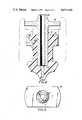
- FIG. 4is an axially extending cross-sectional view of another embodiment of the inlet valve assembly.
- FIG. 5is a top end view of the stem illustrated in FIG. 4.
- an inlet valve assembly 1is illustrated consisting of a shaped valve member 2 formed of a flexible material and a stem 4 formed of a rigid material.
- the inlet valve assembly 1is fitted into an opening 6 in a housing 8 which forms a fuel chamber 10, such as a fuel chamber for a gas lighter using liquid petroleum gas.
- the opening 6extends axially outwardly from the inner surface 12 of the fuel chamber 10 and has a first axial extending portion 14, a second axially extending portion 16 and a third axially extending portion 18.
- the first portion 14has the smallest diameter with the diameters increasing outwardly through the second and third portions 16 and 18.
- a first shoulder 20is formed by the inner surface 12 of the housing where it encircles the opening.
- a second shoulder 22is formed which faces outwardly from the fuel chamber 10.
- a third shoulder 24is provided at the junction of the second portion 16 and the third portion 18.
- the valve member 2is fitted into the opening 6 and has a first end 26 facing outwardly and a second end 28 located within the fuel chamber 10. Extending between the ends, the outer wall surface of the valve member is generally cylindrically shaped, however, the outer wall surface is configured so that it fits in sealing engagement with the surface of the first portion 14 of the opening 6.
- the outer surface of the valve memberincludes a first annular or toroidally shaped protuberance 30 extending from the first end of the valve member.
- a second annular or toroidally shaped protuberance 32is spaced axially from the first protuberance and is located within the fuel chamber. Extending axially between the two protuberances is an annular recessed portion 34.
- the diameter of the recessed portion 34 relative to the diameter of the first portion 14 of the openingis such that the flexible material forming the valve member fits in tight sealing engagement with the surface of the first portion 14 of the opening. Further, the axial length of the annular recessed portion 34 extending between the shoulder 36 on the first protuberance and the shoulder 38 on the second protuberance is less than the axial length of the first portion. Due to this axial length differential, when the valve member is inserted into the opening with the shoulders 36 and 38 on the protuberances in engagement with the shoulders 22, 20, respectively, on the housing, the valve member is stretched and, because of its flexible character, it provides a squeezing action against the opposite ends of the first portion 14.
- a bore 40extends centrally through the valve member from the first end 26 to a position closely spaced from the second end 28.
- the borehas a uniform diameter from the first end 26 to a location in the range of the shoulder 38 on the protuberance 32 where the bore is widened by an annular groove 42 which projects outwardly from the adjacent uniform diameter portion of the bore. From the annular groove 42 to the end of the bore adjacent the second end of the valve member 28, the bore narrows down and terminates in a slit 44 extending between the second end of the valve member and the adjacent end of the bore. Because of the flexible character of the valve member, when pressurized fuel is contained within the chamber 10 and the bore 40 is exposed to atmospheric pressure, the pressure of the fuel keeps the slit closed so that there is no leakage or loss of pressure within the chamber.
- the second end 28 of the valve chamberis spaced axially from the second protuberance 32 and the outer surfaces of the valve member taper inwardly from the protuberance to the second end.
- the stem 4fits within the bore 40 in the valve member.
- Stem 4has a first end 50 projecting outwardly from the valve member and a second end 52 seated against the inner surface of the bore formed by the junction between the inner end of the annular groove 42 and the inner tapering end of the bore.
- the stemhas a toroidally shaped projecting portion 54 which seats in form fitting engagement with the surface of the annular groove 42 in the bore.
- the portion 56 of the stemextending axially outwardly from the projecting portion 54 has approximately the same diameter as the bore 40 in the valve member so that it fits tightly within the bore.
- the stemOutwardly from the first end 26 of the valve member, the stem has a reduced diameter portion 58 which terminates at the first end 50 of the stem.
- a groove 60is formed in the outer surface of the member and extends axially to its first end 26.
- the grooveextends through a major portion of the annular recessed portion 34 and through the full axial length of the first protuberance 30 of the valve member.
- the groove 60is closed off from the interior of the fuel chamber 10 by the protuberance 32 and the small axial length of the annular recess portion 34 extending between the shoulder 38 and the adjacent end of the groove.
- the inlet valve assemblyis in sealed engagement within the opening 6 in the fuel chamber 10 with the contacting shoulders 20 and 38 blocking any leakage outwardly from the fuel chamber between the contacting surfaces of the opening 6 and the valve member 2.
- the multi-fill tip nozzle 62 on a refill containernot shown, is pressed against the first end 50 of the stem 4 depressing the stem inwardly through the valve member toward the chamber 10.
- the nozzle 60presses the stem inwardly until the it contacts the third shoulder 24 formed in the opening. In this position the inward movement of the stem stretches the valve member and displaces the shoulder 38 out of contact with the shoulder 20 on the housing.
- the extent to which the stem is depressed inwardlyis sufficient to bias the annular recessed portion 34 of the valve member into the valve chamber so that the inner end of the groove 60 is open to the chamber. Since the groove is open to the ambient atmosphere the interior of the chamber 10 is exposed to atmospheric pressure, and with the nozzle 60 pressed against the stem, flow from the refill container passes through the bore 64 in the stem into the end of the bore 40 in the opposite end of the valve member. The pressure of the inflowing fluid from the fill container being greater than atmospheric pressure causes the slit 44 to open permitting the chamber to be filled. Air within the chamber is exhausted through the groove 60.
- a liquid sprayis forced out of the chamber through the groove 60 signalling that the filling operation has been completed and that the nozzle 60 should be removed from the end of the stem.
- the flexible character of the valve member 2causes it to return to the position shown in FIG. 2 with the first end 50 of the stem 4 moving outwardly away from the first end 26 of the valve member.
- the inlet valve assemblyis again in sealing contact with the housing preventing any leakage out of the fuel chamber.
- the pressure differential between the multi-fill container and the fuel chamber 10assures that a rapid filling of the chamber can be carried out in a single operation without the necessity to effect the filling in several stages as is required with many of the presently used inlet valves.
- the rigid stem 4With the rigid stem 4 in place within the valve member 2 it provides internal support preventing any collapse of the valve wall under the internal fuel chamber pressure.
- the support provided by the stemaids in preventing any leakage between the valve member and the walls of the opening.
- the projecting portion on the end of the stemalso assures that the valve member is adequately held within the opening in the housing.
- valve assemblyconsists of a valve member 2' and a stem 4'.
- the valve member 2'is similar to valve member 2 without the annular groove 42 within its bore.
- Stem 4'is similar to stem 4 but without the projecting portion 54. It has a first end 50' projecting outwardly from the valve member and a second end 52' located at the inner end of the bore 40' in the valve member.
- the outer surface of the stem 4'is continuous without any projecting portions, and is in tightly fitting engagement with the valve member.
- the flange 70On the stem 4', between the first end 26' of the valve member and its first end 50', is an outwardly extending flange 70 which acts as a stop for the inward movement of the stem. As indicated in FIG. 5, the flange 70 has a generally rectangular shape.
- the stemprovides adequate support for the valve member to prevent it from being accidentally displaced from the opening in the housing forming the fuel chamber.
- the inward movement of the stemcauses the valve member to stretch and open the interior of the fuel chamber to the ambient atmosphere.
- the flange 70 on the stemacts as a stop preventing any further inward movement of the stem.
- a typical material for use in the valve member in nitrileany elastomeric material which is compatible with butane and has the required elastic properties could be used.
- a typical material for the stemwould be brass, however, a suitable plastic material or a zinc die casting could also be used.
Landscapes
- Engineering & Computer Science (AREA)
- General Engineering & Computer Science (AREA)
- Mechanical Engineering (AREA)
- Chemical & Material Sciences (AREA)
- Combustion & Propulsion (AREA)
- Lighters Containing Fuel (AREA)
- Nozzles (AREA)
Abstract
Description
Claims (20)
Priority Applications (8)
| Application Number | Priority Date | Filing Date | Title |
|---|---|---|---|
| US05/754,037US4077429A (en) | 1976-12-23 | 1976-12-23 | Push-fit inlet valve assembly |
| NL7714106ANL7714106A (en) | 1976-12-23 | 1977-12-20 | INTAKE VALVE ASSEMBLY FOR FUEL TANK. |
| AU31915/77AAU3191577A (en) | 1976-12-23 | 1977-12-22 | Valve assembly |
| ES465330AES465330A1 (en) | 1976-12-23 | 1977-12-22 | Push-fit inlet valve assembly |
| GB53543/77AGB1554813A (en) | 1976-12-23 | 1977-12-22 | Valve assembly |
| FR7738760AFR2375528A1 (en) | 1976-12-23 | 1977-12-22 | INTAKE VALVE SYSTEM FOR FUEL TANK, ESPECIALLY GAS LIGHTER |
| IT31149/77AIT1089217B (en) | 1976-12-23 | 1977-12-22 | VALVE GROUP |
| BE183822ABE862294A (en) | 1976-12-23 | 1977-12-23 | INTAKE VALVE ASSEMBLY FOR FUEL TANK |
Applications Claiming Priority (1)
| Application Number | Priority Date | Filing Date | Title |
|---|---|---|---|
| US05/754,037US4077429A (en) | 1976-12-23 | 1976-12-23 | Push-fit inlet valve assembly |
Publications (1)
| Publication Number | Publication Date |
|---|---|
| US4077429Atrue US4077429A (en) | 1978-03-07 |
Family
ID=25033228
Family Applications (1)
| Application Number | Title | Priority Date | Filing Date |
|---|---|---|---|
| US05/754,037Expired - LifetimeUS4077429A (en) | 1976-12-23 | 1976-12-23 | Push-fit inlet valve assembly |
Country Status (8)
| Country | Link |
|---|---|
| US (1) | US4077429A (en) |
| AU (1) | AU3191577A (en) |
| BE (1) | BE862294A (en) |
| ES (1) | ES465330A1 (en) |
| FR (1) | FR2375528A1 (en) |
| GB (1) | GB1554813A (en) |
| IT (1) | IT1089217B (en) |
| NL (1) | NL7714106A (en) |
Cited By (37)
| Publication number | Priority date | Publication date | Assignee | Title |
|---|---|---|---|---|
| FR2513285A1 (en)* | 1981-09-22 | 1983-03-25 | Bayard Sa Ets | Decompressor for water hydrant - comprises valve in each outlet plug which is automatically depressed on removal |
| US4524805A (en)* | 1983-07-08 | 1985-06-25 | Hoffman Allan C | Normally closed duckbill valve and method of manufacture |
| WO1987003062A1 (en)* | 1985-11-07 | 1987-05-21 | Sundstrand Corporation | Pressure relief and vacuum vent valve |
| US4690377A (en)* | 1986-03-18 | 1987-09-01 | Tokai Corporation | High-pressure gas filling valve for use in a pressure resistant container |
| US4802513A (en)* | 1981-05-07 | 1989-02-07 | Ciba-Geigy Corporation | Closed system chemical container |
| US4813453A (en)* | 1987-04-21 | 1989-03-21 | Borg-Warner Automotive, Inc. | Vehicle fuel tank vapor recovery system |
| US4854486A (en)* | 1987-05-11 | 1989-08-08 | Ciba Corning Diagnostics Corp. | Resealable container for dispensing liquid |
| US5277577A (en)* | 1991-08-19 | 1994-01-11 | Minitek Feinmechanische Produkte Gesellschaft M.B.H. | One-way valve for fluids |
| US5381563A (en)* | 1992-12-24 | 1995-01-17 | Roger Carrier | Check valve, and hydromassaging apparatus comprising at least one of such a check valve |
| EP0777074A3 (en)* | 1995-10-30 | 1997-10-01 | Draeger Ltd | Improvements in or relating to relief valves |
| US6453940B1 (en)* | 1999-12-20 | 2002-09-24 | Federal-Mogul Corporation | Insert bonded combination valve |
| EP1027901A3 (en)* | 1999-02-10 | 2003-04-16 | Daiken Iki Kabushiki Kaisha | A backflow prevention structure for a liquid medicine injection device |
| US20040072114A1 (en)* | 2002-06-26 | 2004-04-15 | Michel Doucet | Gas lighter |
| US6959742B2 (en) | 2003-01-31 | 2005-11-01 | Ronson Corporation | Fuel transfer adaptor |
| US20050257837A1 (en)* | 2004-05-19 | 2005-11-24 | Bailey James C | Combination umbrella and inverted bi-directional valve |
| US20060264278A1 (en)* | 2003-03-17 | 2006-11-23 | David Horton | Sports ball valve |
| US20110008738A1 (en)* | 2008-03-10 | 2011-01-13 | Societe Bic | Gas lighter and method for manufacturing same |
| US20130220482A1 (en)* | 2012-02-29 | 2013-08-29 | OECO-Tech, Entwicklung und Vertrieb von Verpackungssystemen GmbH | Refillable dispensing container |
| JP2014112032A (en)* | 2014-02-07 | 2014-06-19 | Soc Bic | Gas lighter and method of manufacturing gas lighter |
| US20150377486A1 (en)* | 2013-03-05 | 2015-12-31 | SOCIéTé BIC | Sealing Assembly to Fill and Seal A Reservoir or a Disposable Gas Lighter |
| US20160178295A1 (en)* | 2014-12-19 | 2016-06-23 | Icejet, S.L. | Methods and apparatus for cooling liquids in portable containers |
| US9618130B1 (en) | 2015-11-29 | 2017-04-11 | Trong D Nguyen | Multi-purpose valve for extending shelf-life using vacuuming or injecting gas |
| US10151396B2 (en) | 2015-11-29 | 2018-12-11 | Trong D Nguyen | Multi-purpose valve for vacuuming, de-vacuuming, gas injecting and pressure regulating |
| WO2019067816A1 (en)* | 2017-09-29 | 2019-04-04 | Quest Engines, LLC | Apparatus and methods for controlling the movement of matter |
| US10465629B2 (en) | 2017-03-30 | 2019-11-05 | Quest Engines, LLC | Internal combustion engine having piston with deflector channels and complementary cylinder head |
| US10526953B2 (en) | 2017-03-30 | 2020-01-07 | Quest Engines, LLC | Internal combustion engine |
| US10590813B2 (en) | 2017-03-30 | 2020-03-17 | Quest Engines, LLC | Internal combustion engine |
| US10590834B2 (en) | 2017-03-30 | 2020-03-17 | Quest Engines, LLC | Internal combustion engine |
| US10598285B2 (en) | 2017-03-30 | 2020-03-24 | Quest Engines, LLC | Piston sealing system |
| US10724428B2 (en) | 2017-04-28 | 2020-07-28 | Quest Engines, LLC | Variable volume chamber device |
| US10753267B2 (en) | 2018-01-26 | 2020-08-25 | Quest Engines, LLC | Method and apparatus for producing stratified streams |
| US10753308B2 (en) | 2017-03-30 | 2020-08-25 | Quest Engines, LLC | Internal combustion engine |
| US10827659B2 (en) | 2015-11-29 | 2020-11-03 | Trong D Nguyen | Personal microwave autoclave and process using the same for sterilizing N95 masks |
| US10883498B2 (en) | 2017-05-04 | 2021-01-05 | Quest Engines, LLC | Variable volume chamber for interaction with a fluid |
| US10989138B2 (en) | 2017-03-30 | 2021-04-27 | Quest Engines, LLC | Internal combustion engine |
| US11041456B2 (en) | 2017-03-30 | 2021-06-22 | Quest Engines, LLC | Internal combustion engine |
| US11134335B2 (en) | 2018-01-26 | 2021-09-28 | Quest Engines, LLC | Audio source waveguide |
Families Citing this family (1)
| Publication number | Priority date | Publication date | Assignee | Title |
|---|---|---|---|---|
| CN114576650A (en)* | 2022-04-06 | 2022-06-03 | 熊宇鹏 | Oil supply device of kerosene lighter |
Citations (10)
| Publication number | Priority date | Publication date | Assignee | Title |
|---|---|---|---|---|
| US3217762A (en)* | 1963-07-19 | 1965-11-16 | Kreisler Mfg Corp Jacques | Refill valve for gas lighter |
| US3277674A (en)* | 1963-03-29 | 1966-10-11 | Ronson Corp | Burner-inlet valve for gas lighters |
| US3414025A (en)* | 1966-04-18 | 1968-12-03 | Scripto Inc | Fill nozzle |
| US3464442A (en)* | 1966-09-26 | 1969-09-02 | Crown Sangyo Kk | Liquefied gas lighter |
| US3473704A (en)* | 1967-04-18 | 1969-10-21 | Valve Corp Of America | Venting valve construction for refillable pressurized dispensers |
| US3540402A (en)* | 1968-10-29 | 1970-11-17 | Parker Hannifin Corp | Liquid dispensing device |
| US3718165A (en)* | 1969-12-08 | 1973-02-27 | G Grothoff | Refillable aerosol dispenser |
| US3746059A (en)* | 1969-07-29 | 1973-07-17 | Mitani Valve Co Ltd | Gas injection for gas lighters |
| US3871422A (en)* | 1973-02-14 | 1975-03-18 | Automatic Helium Balloon Syste | Dual balloon valve |
| US3941149A (en)* | 1974-11-11 | 1976-03-02 | Baxter Laboratories, Inc. | Valve |
- 1976
- 1976-12-23USUS05/754,037patent/US4077429A/ennot_activeExpired - Lifetime
- 1977
- 1977-12-20NLNL7714106Apatent/NL7714106A/ennot_activeApplication Discontinuation
- 1977-12-22AUAU31915/77Apatent/AU3191577A/enactivePending
- 1977-12-22GBGB53543/77Apatent/GB1554813A/ennot_activeExpired
- 1977-12-22ESES465330Apatent/ES465330A1/ennot_activeExpired
- 1977-12-22FRFR7738760Apatent/FR2375528A1/ennot_activeWithdrawn
- 1977-12-22ITIT31149/77Apatent/IT1089217B/enactive
- 1977-12-23BEBE183822Apatent/BE862294A/enunknown
Patent Citations (10)
| Publication number | Priority date | Publication date | Assignee | Title |
|---|---|---|---|---|
| US3277674A (en)* | 1963-03-29 | 1966-10-11 | Ronson Corp | Burner-inlet valve for gas lighters |
| US3217762A (en)* | 1963-07-19 | 1965-11-16 | Kreisler Mfg Corp Jacques | Refill valve for gas lighter |
| US3414025A (en)* | 1966-04-18 | 1968-12-03 | Scripto Inc | Fill nozzle |
| US3464442A (en)* | 1966-09-26 | 1969-09-02 | Crown Sangyo Kk | Liquefied gas lighter |
| US3473704A (en)* | 1967-04-18 | 1969-10-21 | Valve Corp Of America | Venting valve construction for refillable pressurized dispensers |
| US3540402A (en)* | 1968-10-29 | 1970-11-17 | Parker Hannifin Corp | Liquid dispensing device |
| US3746059A (en)* | 1969-07-29 | 1973-07-17 | Mitani Valve Co Ltd | Gas injection for gas lighters |
| US3718165A (en)* | 1969-12-08 | 1973-02-27 | G Grothoff | Refillable aerosol dispenser |
| US3871422A (en)* | 1973-02-14 | 1975-03-18 | Automatic Helium Balloon Syste | Dual balloon valve |
| US3941149A (en)* | 1974-11-11 | 1976-03-02 | Baxter Laboratories, Inc. | Valve |
Cited By (43)
| Publication number | Priority date | Publication date | Assignee | Title |
|---|---|---|---|---|
| US4802513A (en)* | 1981-05-07 | 1989-02-07 | Ciba-Geigy Corporation | Closed system chemical container |
| FR2513285A1 (en)* | 1981-09-22 | 1983-03-25 | Bayard Sa Ets | Decompressor for water hydrant - comprises valve in each outlet plug which is automatically depressed on removal |
| US4524805A (en)* | 1983-07-08 | 1985-06-25 | Hoffman Allan C | Normally closed duckbill valve and method of manufacture |
| WO1987003062A1 (en)* | 1985-11-07 | 1987-05-21 | Sundstrand Corporation | Pressure relief and vacuum vent valve |
| US4926908A (en)* | 1985-11-07 | 1990-05-22 | Sundstrand Corporation | Pressure relief and vacuum vent valve |
| US4690377A (en)* | 1986-03-18 | 1987-09-01 | Tokai Corporation | High-pressure gas filling valve for use in a pressure resistant container |
| US4813453A (en)* | 1987-04-21 | 1989-03-21 | Borg-Warner Automotive, Inc. | Vehicle fuel tank vapor recovery system |
| US4854486A (en)* | 1987-05-11 | 1989-08-08 | Ciba Corning Diagnostics Corp. | Resealable container for dispensing liquid |
| US5277577A (en)* | 1991-08-19 | 1994-01-11 | Minitek Feinmechanische Produkte Gesellschaft M.B.H. | One-way valve for fluids |
| US5381563A (en)* | 1992-12-24 | 1995-01-17 | Roger Carrier | Check valve, and hydromassaging apparatus comprising at least one of such a check valve |
| EP0777074A3 (en)* | 1995-10-30 | 1997-10-01 | Draeger Ltd | Improvements in or relating to relief valves |
| EP1027901A3 (en)* | 1999-02-10 | 2003-04-16 | Daiken Iki Kabushiki Kaisha | A backflow prevention structure for a liquid medicine injection device |
| US6453940B1 (en)* | 1999-12-20 | 2002-09-24 | Federal-Mogul Corporation | Insert bonded combination valve |
| US20040072114A1 (en)* | 2002-06-26 | 2004-04-15 | Michel Doucet | Gas lighter |
| US6959742B2 (en) | 2003-01-31 | 2005-11-01 | Ronson Corporation | Fuel transfer adaptor |
| US20060264278A1 (en)* | 2003-03-17 | 2006-11-23 | David Horton | Sports ball valve |
| US20050257837A1 (en)* | 2004-05-19 | 2005-11-24 | Bailey James C | Combination umbrella and inverted bi-directional valve |
| US7243676B2 (en)* | 2004-05-19 | 2007-07-17 | Vernay Laboratories, Inc. | Combination umbrella and inverted bi-directional valve |
| US20110008738A1 (en)* | 2008-03-10 | 2011-01-13 | Societe Bic | Gas lighter and method for manufacturing same |
| US8979527B2 (en)* | 2008-03-10 | 2015-03-17 | Societe Bic | Gas lighter and method for manufacturing same |
| US20130220482A1 (en)* | 2012-02-29 | 2013-08-29 | OECO-Tech, Entwicklung und Vertrieb von Verpackungssystemen GmbH | Refillable dispensing container |
| US10125989B2 (en)* | 2013-03-05 | 2018-11-13 | Bic Violex S.A. | Sealing assembly to fill and seal a reservoir or a disposable gas lighter |
| US20150377486A1 (en)* | 2013-03-05 | 2015-12-31 | SOCIéTé BIC | Sealing Assembly to Fill and Seal A Reservoir or a Disposable Gas Lighter |
| JP2014112032A (en)* | 2014-02-07 | 2014-06-19 | Soc Bic | Gas lighter and method of manufacturing gas lighter |
| US20160178295A1 (en)* | 2014-12-19 | 2016-06-23 | Icejet, S.L. | Methods and apparatus for cooling liquids in portable containers |
| US9618130B1 (en) | 2015-11-29 | 2017-04-11 | Trong D Nguyen | Multi-purpose valve for extending shelf-life using vacuuming or injecting gas |
| US10151396B2 (en) | 2015-11-29 | 2018-12-11 | Trong D Nguyen | Multi-purpose valve for vacuuming, de-vacuuming, gas injecting and pressure regulating |
| US10827659B2 (en) | 2015-11-29 | 2020-11-03 | Trong D Nguyen | Personal microwave autoclave and process using the same for sterilizing N95 masks |
| US10598285B2 (en) | 2017-03-30 | 2020-03-24 | Quest Engines, LLC | Piston sealing system |
| US10753308B2 (en) | 2017-03-30 | 2020-08-25 | Quest Engines, LLC | Internal combustion engine |
| US10590813B2 (en) | 2017-03-30 | 2020-03-17 | Quest Engines, LLC | Internal combustion engine |
| US10590834B2 (en) | 2017-03-30 | 2020-03-17 | Quest Engines, LLC | Internal combustion engine |
| US10465629B2 (en) | 2017-03-30 | 2019-11-05 | Quest Engines, LLC | Internal combustion engine having piston with deflector channels and complementary cylinder head |
| US11041456B2 (en) | 2017-03-30 | 2021-06-22 | Quest Engines, LLC | Internal combustion engine |
| US10989138B2 (en) | 2017-03-30 | 2021-04-27 | Quest Engines, LLC | Internal combustion engine |
| US10526953B2 (en) | 2017-03-30 | 2020-01-07 | Quest Engines, LLC | Internal combustion engine |
| US10724428B2 (en) | 2017-04-28 | 2020-07-28 | Quest Engines, LLC | Variable volume chamber device |
| US10883498B2 (en) | 2017-05-04 | 2021-01-05 | Quest Engines, LLC | Variable volume chamber for interaction with a fluid |
| US10808866B2 (en) | 2017-09-29 | 2020-10-20 | Quest Engines, LLC | Apparatus and methods for controlling the movement of matter |
| WO2019067816A1 (en)* | 2017-09-29 | 2019-04-04 | Quest Engines, LLC | Apparatus and methods for controlling the movement of matter |
| US11060636B2 (en) | 2017-09-29 | 2021-07-13 | Quest Engines, LLC | Engines and pumps with motionless one-way valve |
| US10753267B2 (en) | 2018-01-26 | 2020-08-25 | Quest Engines, LLC | Method and apparatus for producing stratified streams |
| US11134335B2 (en) | 2018-01-26 | 2021-09-28 | Quest Engines, LLC | Audio source waveguide |
Also Published As
| Publication number | Publication date |
|---|---|
| BE862294A (en) | 1978-04-14 |
| FR2375528A1 (en) | 1978-07-21 |
| GB1554813A (en) | 1979-10-31 |
| ES465330A1 (en) | 1979-06-01 |
| AU3191577A (en) | 1979-06-28 |
| IT1089217B (en) | 1985-06-18 |
| NL7714106A (en) | 1978-06-27 |
Similar Documents
| Publication | Publication Date | Title |
|---|---|---|
| US4077429A (en) | Push-fit inlet valve assembly | |
| US2658714A (en) | Dispenser valve assembly | |
| US2721010A (en) | Aerosol containers and valves therefor | |
| US6039306A (en) | Aerosol valve | |
| US5018552A (en) | Valve assembly for packing fluid under pressure and packing provided with such assembly | |
| US5014887A (en) | Valve for a container for dispensing a pressurized fluid | |
| US2968427A (en) | Valve for aerosol container | |
| US2914224A (en) | Valve assembly for pressure containers and the like | |
| US6322051B1 (en) | Elastomeric molded valve stem and spring hat | |
| GB669316A (en) | Improvements in or relating to dispensing apparatus for fluids | |
| US3589618A (en) | Plug valve assembly for fluid product dispenser having retaining ring supporting a propellant cartridge | |
| CA1225069A (en) | Aerosol valves | |
| IL40069A (en) | A grease box for automatically dispensing lubricant | |
| KR900018577A (en) | Push Fluid Dispenser | |
| WO2002036959A3 (en) | Fluid dosing device with a throttle point | |
| KR860000552A (en) | Leak measuring device of valve packing | |
| EP1590597B1 (en) | Overpressure safety apparatus of gas fuel container | |
| US3054536A (en) | Valve and closure construction for aerosol devices | |
| US3624755A (en) | Connecting devices for the fluidtight flow of fluid between two enclosures | |
| US4135649A (en) | Liquid dispensing tap | |
| US3128924A (en) | Metered valve construction | |
| US3800979A (en) | Lpg valve assembly | |
| US3144179A (en) | Aerosol valve | |
| US3109625A (en) | Valve construction for aerosolproducing device | |
| RU2123940C1 (en) | Container for ink (versions) and recorder using such container |
Legal Events
| Date | Code | Title | Description |
|---|---|---|---|
| AS | Assignment | Owner name:NIHON SIBER HEGNER, K.K. Free format text:SECURITY INTEREST;ASSIGNOR:RONSON CORPORATION A CORP OF NJ;REEL/FRAME:004286/0886 Effective date:19840314 | |
| AS | Assignment | Owner name:LAZERE FINANCIAL CORPORATION 60 EAST 42ND STREET, Free format text:SECURITY INTEREST;ASSIGNOR:RONSON CORPORATION;REEL/FRAME:004304/0018 Effective date:19840516 Owner name:SECURITY PACIFIC BUSINESS CREDIT INC., 228 EAST 45 Free format text:SECURITY INTEREST;ASSIGNOR:RONSON CORPORATION;REEL/FRAME:004304/0018 Effective date:19840516 | |
| AS | Assignment | Owner name:FOOTHILL CAPITAL CORPORATION, A CORP. OF CA, ILLIN Free format text:SECURITY INTEREST;ASSIGNOR:RONSON CORPORATION;REEL/FRAME:004431/0132 Effective date:19850614 | |
| AS | Assignment | Owner name:THE CIT GROUP/COMMERCIAL SERVICES, INC., NEW YORK Free format text:SECURITY AGREEMENT;ASSIGNOR:RONSON CORPORATION;REEL/FRAME:018039/0735 Effective date:20060731 | |
| AS | Assignment | Owner name:WELLS FARGO BANK, NATIONAL ASSOCIATION, NEW YORK Free format text:SECURITY AGREEMENT;ASSIGNOR:RONSON CORPORATION;REEL/FRAME:021085/0293 Effective date:20080530 | |
| AS | Assignment | Owner name:WELLS FARGO BANK, NATIONAL ASSOCIATION, NEW YORK Free format text:PATENT SECURITY AGREEMENT;ASSIGNOR:RONSON CORPORATION;REEL/FRAME:021253/0658 Effective date:20080531 | |
| AS | Assignment | Owner name:RONSON CORPORATION, NEW JERSEY Free format text:RELEASE OF SECURITY INTEREST IN PATENTS;ASSIGNOR:WELLS FARGO FOOTHILL, INC.;REEL/FRAME:022248/0313 Effective date:20090209 | |
| AS | Assignment | Owner name:RONSON CORPORATION, NEW JERSEY Free format text:RELEASE OF SECURITY INTEREST IN PATENTS;ASSIGNOR:THE CIT GROUP/COMMERCIAL SERVICES, INC.;REEL/FRAME:022449/0751 Effective date:20090324 | |
| AS | Assignment | Owner name:WELLS FARGO BANK, NATIONAL ASSOCIATION, NEW YORK Free format text:AMENDED AND RESTATED PATENT SECURITY AGREEMENT;ASSIGNOR:RONSON CORPORATION;REEL/FRAME:022460/0684 Effective date:20090330 | |
| AS | Assignment | Owner name:GETZLER HENRICH & ASSOCIATES LLC, NEW YORK Free format text:SECURITY AGREEMENT;ASSIGNOR:RONSON CORPORATION;REEL/FRAME:022520/0046 Effective date:20090330 |