US4068232A - Passive encoding microwave transponder - Google Patents
Passive encoding microwave transponderDownload PDFInfo
- Publication number
- US4068232A US4068232AUS05/657,467US65746776AUS4068232AUS 4068232 AUS4068232 AUS 4068232AUS 65746776 AUS65746776 AUS 65746776AUS 4068232 AUS4068232 AUS 4068232A
- Authority
- US
- United States
- Prior art keywords
- interrogator
- transponder
- frequency signal
- receiving
- signal
- Prior art date
- Legal status (The legal status is an assumption and is not a legal conclusion. Google has not performed a legal analysis and makes no representation as to the accuracy of the status listed.)
- Expired - Lifetime
Links
Images


Classifications
- B—PERFORMING OPERATIONS; TRANSPORTING
- B61—RAILWAYS
- B61L—GUIDING RAILWAY TRAFFIC; ENSURING THE SAFETY OF RAILWAY TRAFFIC
- B61L25/00—Recording or indicating positions or identities of vehicles or trains or setting of track apparatus
- B61L25/02—Indicating or recording positions or identities of vehicles or trains
- B61L25/04—Indicating or recording train identities
- B61L25/045—Indicating or recording train identities using reradiating tags
- B—PERFORMING OPERATIONS; TRANSPORTING
- B07—SEPARATING SOLIDS FROM SOLIDS; SORTING
- B07C—POSTAL SORTING; SORTING INDIVIDUAL ARTICLES, OR BULK MATERIAL FIT TO BE SORTED PIECE-MEAL, e.g. BY PICKING
- B07C3/00—Sorting according to destination
- B07C3/10—Apparatus characterised by the means used for detection ofthe destination
- B07C3/12—Apparatus characterised by the means used for detection ofthe destination using electric or electronic detecting means
- G—PHYSICS
- G01—MEASURING; TESTING
- G01S—RADIO DIRECTION-FINDING; RADIO NAVIGATION; DETERMINING DISTANCE OR VELOCITY BY USE OF RADIO WAVES; LOCATING OR PRESENCE-DETECTING BY USE OF THE REFLECTION OR RERADIATION OF RADIO WAVES; ANALOGOUS ARRANGEMENTS USING OTHER WAVES
- G01S13/00—Systems using the reflection or reradiation of radio waves, e.g. radar systems; Analogous systems using reflection or reradiation of waves whose nature or wavelength is irrelevant or unspecified
- G01S13/74—Systems using reradiation of radio waves, e.g. secondary radar systems; Analogous systems
- G01S13/75—Systems using reradiation of radio waves, e.g. secondary radar systems; Analogous systems using transponders powered from received waves, e.g. using passive transponders, or using passive reflectors
- G01S13/751—Systems using reradiation of radio waves, e.g. secondary radar systems; Analogous systems using transponders powered from received waves, e.g. using passive transponders, or using passive reflectors wherein the responder or reflector radiates a coded signal
- G01S13/758—Systems using reradiation of radio waves, e.g. secondary radar systems; Analogous systems using transponders powered from received waves, e.g. using passive transponders, or using passive reflectors wherein the responder or reflector radiates a coded signal using a signal generator powered by the interrogation signal
- G—PHYSICS
- G06—COMPUTING OR CALCULATING; COUNTING
- G06K—GRAPHICAL DATA READING; PRESENTATION OF DATA; RECORD CARRIERS; HANDLING RECORD CARRIERS
- G06K7/00—Methods or arrangements for sensing record carriers, e.g. for reading patterns
- G06K7/10—Methods or arrangements for sensing record carriers, e.g. for reading patterns by electromagnetic radiation, e.g. optical sensing; by corpuscular radiation
- G06K7/10009—Methods or arrangements for sensing record carriers, e.g. for reading patterns by electromagnetic radiation, e.g. optical sensing; by corpuscular radiation sensing by radiation using wavelengths larger than 0.1 mm, e.g. radio-waves or microwaves
- G—PHYSICS
- G08—SIGNALLING
- G08G—TRAFFIC CONTROL SYSTEMS
- G08G1/00—Traffic control systems for road vehicles
- G08G1/01—Detecting movement of traffic to be counted or controlled
- G08G1/017—Detecting movement of traffic to be counted or controlled identifying vehicles
Definitions
- the present inventionovercomes all these foregoing disadvantages and provides a simple, inexpensive, small, passive transponder which may be readily mounted in many orientations on the object to be identified and permits unambiguous identification and reception of the transponder signal and a method of using such a transponder.
- This inventionrelates to marking apparatus and more particularly to marking apparatus for marking objects with a transponder for the purpose of transmitting identifying information about an object or its location.
- FIG. 1is a drawing showing the use of the passive transponder of the present invention with an interrogator in a vehicle identification application;
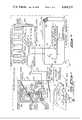
- FIG. 2is a circuit diagram of a portion of the structure illustrated in FIG. 1 showing the passive transponder and an interrogator useable in a vehicle identification application;
- FIG. 3is an exploded detailed view of the circuitry of the passive transponder of FIG. 2 used to receive the incident beam and generate harmonic energy including a harmonic generator, the power supply structure and logic circuitry;
- FIG. 4is a circuit diagram of the logic circuitry which comprises the clock and control circuitry, the ROM and the modulator in FIG. 2;
- FIG. 5is a typical split phase bit stream waveform that is generated by the circuitry illustrated in FIG. 4 and fed to the modulator;
- FIG. 6is a circuit diagram showing an alternate logic circuitry embodiment which may be utilized in the transponder in place of the circuitry illustrated in FIG. 4.
- a truck 10is proceeding along a roadway 15 and passes through an interrogator beam 17 from the interrogator 12. Energy from this beam is incident upon a passive transponder 20 which uses a portion of that beam energy to provide power for circuity contained within the transponder 20.
- the transponder 20which received the incident beam 17 from the interrogator passively generates and transmits harmonic energy to the interrogator in the form of a beam 18.
- the harmonic response from the transponder 20is keyed on and off according to a pre-programmed serial digital code which is stored in and read out by digital circuitry in the transponder 20 in a manner which will be more fully described hereinafter. This digital circuitry is powered by a portion of the beam 17 energy from the interrogator.
- the coded response beam 18 from the transponder 20is received, detected and decoded within the interrogator 12.
- the decoded informationis presented on a display unit 14 which is connected to the interrogator 12 and may be visual or which may input written or electronic data to an automatic security or billing system.
- the numbermay be a multi-digit alpha-numeric character and the display can be utilized to convey the identity or class of the vehicle or its cargo.
- the system utilized in FIG. 1includes an interrogator 12, a passive transponder 20 and a display unit 14.
- the interrogator 12contains an oscillator 102 which generates the fundamental frequency for the transmitter beam 17. Some of this signal is sampled by the coupler 103 for use in the receiver section 100 of the interrogator. Most of the oscillator 102 output proceeds through the coupler 103 to a power amplifier 104 which provides sufficient power (about 50 watts during interrogation) to power the passive transponder 20 by radiated RF energy in the beam 17. The amplified signal is radiated in the beam 17 to the transponder 20 via the transmitter antenna 105 which is connected to amplifier 104.
- the beam 17 from the interrogator 12is received by two antennas 11 and 21 which are part of the transponder 20.
- the signal from antenna 11is fed via the lead 0 to impedance matching, filtering and rectifying circuitry which makes up the power supply 16.
- the output of the power supply 16is an electrical current with a positive 3-15 volt voltage for operating the clock and control circuitry 29, the ROM (read only memory) 28, and the modulator 27. This current is fed to the control circuitry 29 by the leads 13 and 13a, to the ROM via the lead 13b, and to the modulator 27 via the lead 13b from the ROM 28.
- the filter capacitor in the transponder power supply 16is selected to have small enough capacitance to be rapidly charged when a high incident power level signal is received and to provide rapid discharging of the capacitor at the end of interrogation by that signal.
- the clock and control circuit 29When the power supply 16 voltage is of sufficient magnitude (+3 volts), the clock and control circuit 29 generates pulses which cause the contents of the ROM 28 to be read into the modulator 27 as a serial digital code signal via the lead 28a.
- the modulator 27then applies a DC voltage bias via the lead 27a to the frequency multiplier 24 which turns it on and off forming digital "ones" and “zeros" in response to the voltage bias.
- This DC biasworks to de-tune the resonant structure contained within the frequency multiplier 24 and/or reduce the harmonic conversion efficiency of a harmonic generator contained within the frequency multiplier 24. This combination of effects takes place when the modulator 27 keys the frequency mmultiplier 24 off via the lead 27a.
- the ROM 28contains digital data programmed into it which is read out serially on lead 28a into the modulator 27. Each data bit from the ROM 28 is serially read when the ROM 28 receives a clock pulse via lead 29a from the clock and control circuit 29.
- the clock and control circuit 29generates clock pulses which are sent to the ROM 28 via lead 29a when a pre-determined threshold voltage is reached on the power supply line 13a.
- a certain pre-determined signal level from the interrogator 12is required to produce the threshold voltage on lead 13a before operation of the clock and control circuit 29 will commence. No information from the read-only memory 28 will be provided for the modulator 27 until clock pulses occur.
- the clock and control circuit 29 operating frequencyvaries by design in proportion to the voltage on lead 13a to provide a means for automatically controlling the signal to noise ratio of the detected signal from the transponder 20 and for increasing the dynamic range of such operation as follows.
- a greater energy levelis received by the transponder 20 from the interrogator beam 17, a larger voltage is produced from the power supply 16.
- This greater voltage on lead 13acauses the clock oscillator in the clock and control circuitry to run at a higher frequency.
- a weak interrogator beam 17likewise results in a lower clock frequency.
- a transponder moving at a given constant velocitywill be within the beam for a shorter period of time than at long range owing to the divergence of the interrogator beam, according to the beam width of the tansmitting antenna.
- the transponder data readout rate(clock frequency) is rapid to accommodate the shorter time within the interrogator beam.
- the reduced readout rateallows reduced interrogator receiver noise due to the lower data transmission bandwidth resulting in a more constant signal to noise ratio.
- the receiver bandwithis established by synchronized integrate-and-dump filters in the logic decoder 111. The slower data rate is consistent with the longer time interval during which the transponder is within the interrogator beam at longer range.
- the frequency multiplier 24When turned on by the signal on the lead 27a, the frequency multiplier 24 receives energy from the interrogator beam 17 via antenna 21 and transmission line 23. A harmonic generator within the frequency multiplier 24 then generates harmonics at a multiple n times the fundamental frequency f o of the interrogator beam 17 and sends them via the transmission line 25 where they are radiated as the beam 18 by the antenna 21 to the interrogator 101.
- the interrogator receiver antenna 110receives this beam or signal 18 and passes it through a bandpass filter 109 to a mixer 107.
- the receiver section 100 shownis a modified homodyne type and is comprised of elements 109, 107, 106, 111.
- the mixer local oscillator frequency on line 108ais substantially identical to the received signal 18 since it differs only due to Dopper shifts and FM noise.
- This local oscillator signal on line 108ais produced from the sampled energy obtained via the coupler 103 by the frequency multiplier 108 which generates the same harmonic as did the frequency multiplier 24 in the transponder 20.
- the mixer 107mixes the signal from the frequency multiplier 108 with the signal from the band pass filter 109, and delivers a nearly zero frequency output signal to the envelope detector 106.
- the detector 106outputs a signal proportional to the digitally coded amplitude of the received signal 18 to the logic decoder 111.
- the logic decoder 111uses the detector output signal on lead 106a to generate phase locked clock pulses synchronized to the transponder clock 29. This clock within the logic decoder 111 is then utilized to decode the multidigit serial data from the detector 106 to form a decoded signal on lead 111a which is sent to the display unit 14.
- the display unit 14may be an array of light emitting diode alphanumeric characters which visually shows the decoded tag number obtained over lead 111a from the interrogator 12.
- the interrogator 12is made up of conventional microwave and digital components which in themselves are well known to anyone skilled in the art.
- the transponder logic circuitry represented by the blocks 27, 28, 29,use RCA commercial CMOS digital integrated circuits known for low power consumption which are also well known to anyone skilled in the art.
- the ROM 28is a diode matrix memory such as the HM1-0168 manufactured by Harris Semiconductor Corp. of Melbourne, Florida.
- FIG. 3shows a simple frequency multiplying transponder 20. Fundamental energy from an interrogator, such as that labeled 12 in FIG. 2, is coupled into the cavity backed slot antenna 31.
- the harmonic generator 30is constructed of a thin metal cavity filled with a dielectric.
- the harmonic generator 30is a rectangular shaped laminated structure with thin copper or other suitable outside layers and with a dielectric layer between the copper layers.
- the harmonic generator 30also has an outer copper layer with a rectangular slot which exposes the dielectric layer between the metallic layers.
- the slot 31serves as an antenna and coupling iris to the harmonic generator 30.
- the resonant structuresare a resonant antenna 31, and a structure consisting of an inductive stub 33 which is a transmission line segment less than a quarter wavelength long which resonates with the parallel combination of a capacitor 32 and the capacitive diode 34 when the slot antenna 31 receives a signal 17 from the interrogator 12.
- These components 33, 34, 32are resonant at the fundamental frequency transmitted from the interrogator 12.
- the exact resonant frequencymay be adjusted by varying the variable capacitor 32 which is in parallel with capacitor 37 and the diode 34 which both bridge the cavity 31.
- the harmonic energy produced by the diode 34 as a result of the signal received by the slot antenna 31is radiated back to the interrogator 12 illustrated in FIG. 2 via the slot antenna 31.
- the harmonic energyis generated by the non-linear impedance properties of the diode 34 which produces a non sinusoidal voltage from the fundamental frequency signal current passing through it. This voltage is rich in harmonics of the fundamental frequency.
- a positive bias voltage from the digital circuitry 38is applied to the harmonic generator 30 via the lead 35 and through a current limiting resistor 36 which is connected to the diode 34 and a bypass capacitor 37.
- the capacitor 37allows a DC voltage to be impressed across the diode 34, while the low RF impedance of the bypass capacitor 37 allows the diode 34 to receive the full RF voltage across the slot 31.
- This bias voltageappears across the diode 34 and turns on and off the harmonic output signal by detuning the resonant circuit consisting of elements 32, 33, 34 an/or decreasing the harmonic conversion efficiency of the diode 34.
- the bias voltagedoes the former by decreasing the junction capacitance of the diode 34, and the latter by reducing the AC incremental impedance non-linearity of the diode 34.
- the digital circuitry 38is housed on a printed circuit board and contains the clock and control circuitry 29, the ROM 28 and the modulator 27 which were shown in FIG. 2 in block diagram form.
- the edge connector 38aconnects to the ROM and is used for permanently programming it by passing a large programming current through selected pins of the connector.
- the final portion of the transponder shown as FIG. 3is the power supply section 39 which is a microstrip/stripline structure comprising five consecutive layers; an electrically conductive metallic ground plane 39a, a polystyrene dielectric layer 39b, a metallic electrically conductive circuit layer 39c, a polystyrene dielectric layer 39d and an electrically conductive metallic ground plane 39e.
- the ground plane 39ealso contains on one portion a microstrip antenna 120. This antenna is one-half wavelength long at the fundamental frequency of the signal to be received from the interrogator 12 and is coupled via lead 121 upward through the dielectric 39d to the circuit layer 39c.
- the signal received by the antenna 120passes down a 50 ohm transmission line 122 to a low pass filter 122a which is, for example, a constant-k, m-derived end section low pass filter such as found on page 113 on Microwave Engineer's Handbook Vol. 1, Aertech House, Dedham, Mass. 1971, which is a publication which is well known to those skilled in the art.
- the cutoff frequency, f cshould be chosen to be 1.25f o where f o is the fundamental frequency of the interrogator beam 17. It is obvious to anyone skilled in the art that the operating frequency f o may be chosen anywhere within the microwave frequency spectrum. The choice influences the overall size of the passive choice overall transponder.
- the low pass filter 122aremoves all harmonic signals to prevent spurious harmonic generation and radiation by the power supply section 39.
- the dielectric layersare 1/16 inch thick and the electrically conducting layers are common 1 or 2 ounce copper laminate.
- the laminated layers of the power supply section 39are built up as follows.
- the first layeris a metal ground plane layer 39a directly on top of which is a dielectric layer 39b. Sandwiched between dielectric layers 39b and 39d is the metal circuit layer 39c.
- the top layer 39eis a metal ground plane layer that is laminated to the dielectric layer 39d. Part of ground plane layer 39e is etched away to form the antenna structure 120.
- the fundamental signal from the low pass filter 122ais fed to a voltage doubler circuit consisting of diodes 123, 124, capacitor 125 and DC and RF ground point 126 which connects to the ground plane 39a.
- the diodes 123, 124detect and rectify the incident signal and the resulting charge is stored in the filter capacitor 125 to give it a certain potential or voltage.
- the supply output voltage applied to the transmission line 128is applied to a wavetrap 127 comprising a high impedance quarter wave section of transmission line 128 itself shunted by an open circuited low impedance transmission line segment 129 which is also a quarter wavelength long at the fundamental frequency of the signal 17 from the interrogator 12.
- the supply voltage which is greater than +3 voltsis applied to the leads 130, 131 to power the digital circuit 38.
- FIG. 4shows a preferred embodiment of the ROM 28 and modulator 27 of the invention which were illustrated in block diagram form in FIG. 2.
- the leads 49 and 49aprovide power for the various components illustrated in FIG. 4.
- the ROM and modulator assemblyalso contain an edge connector 38a which is used during ROM programming only.
- the connector pins 41aare connected via leads 41b to fusible links 43. These links are connected to and provide permanently programmed parallel loaded voltage inputs to each static shift register 44 and 45.
- the output of the last shifted register 45is fed to an and-gate 46 which produces a split phase bit stream signal output 47 for modulating the frequency multiplier 24 illustrated in FIG. 2.
- the shift registers 44 and 45are clocked by the variable clock 48 whose frequency is controlled by the positive supply voltage magnitude on lead 49 from the transponder power supply 16 illustrated in FIG. 2.
- the supply voltage on lead 49 and lead 49abecomes positive and a time delay which is equal to the RC charging time constant of a resistor 50 and a capacitor 51 is initiated.
- the voltage on the or-gate inverting input lead 52will build up exponentially until it reaches the threshold voltage of the or-gate 53 at which time the 8 stage counter 54 will initiate the load and shift sequence since the re-set input on lead 55 will go to the low voltage state. Shift and load control occurs as follows.
- the counter 54is held in its re-set condition. At this time, the counter 54 output passes through the or-gate 65 and presents a zero voltage on the load/shift control line 63 which places all shift registers in the load mode. After thresholding of the gate 53 occurs, the counter 54 begins to count up. The non-zero voltage output from the counter 54 produces a digital one on the output line 63 of the or-gate 65 which places the shift registers into shift mode.
- the counterWhen all the data has been sent, the counter will contain the number 144, in the embodiment illustrated in FIG. 4, at which time the gate 66 will produce a digital one signal on its output line 64. This digital one signal will pass through the or-gate 53, re-set the counter 54, re-load the shift registers 44 and 45, and repeat the cycle.
- the contents of shift registers 44 and 45are parallel loaded from the data permanently written into the fusible link memory 43. This information is serially shifted into the and-gate 46 from the last shift register 45. And-gate 46 forms a split phase bit stream on the lead 47 as follows. Two fusible links 43 are used to store the data for each frame such as 57-62 in FIG. 5.
- FIG. 5A sample of the signal output waveform 56 on the lead 47 in FIG. 4 is illustrated in FIG. 5.
- the waveformshows frames 6-11 for illustration, and omits frames 1-5 and frame 12, etc.
- the code used in the waveform 56comprises synchronization frames 57 and 58, followed by a "one" frame 59 which signifies the end of the synchronization information and the beginning of data.
- Datais contained in the remaining frames 60, 61, 62, etc.
- Each data framecontains one pulse which is timed to occur either in the first half or the second half of the frame to convey a binary zero or one.
- Each bi-phase encoded data bit 57-62represents a digital one or a zero, depending upon whether a high state followed by a low state exists in either the second half or the first half of the bit frame, respectively.
- Synchronization information in frames 57 and 58is differentiated from data by the fact that both a digital one and a digital zero are present in each bit frame. This type of synchronization is clearly distinguished from the data and provides a more rapid acquisition by the interrogator clock 111 of FIG. 2 due to the double data frequency present.
- the split phase code 56has the advantage of providing positive synchronization of the interrogator clock 111 in the decoder 111 FIG. 2 and provides a definitive indication of both logic states, i.e. one and zero, without relying on the absence of a signal from the transponder 20 illustrated in FIGS. 1 and 2 to convey a zero.
- Any number of binary digitsmay be sent in serial format by the addition serially of additional frames.
- a 64-bit binary wordis sent over lead 47 during every cycle, plus an 8-frame synchronization code. This requires 144 bits within the shift registers 44, 45.
- the transmit power level from the interrogator 12 of FIGS. 1 and 2is reduced causing the voltage level on lead 49 to drop. Transponder 20 operation then ceases and it reverts to quiescent state.
- the ROM 28 comprising the fusible links 43is encoded by applying a suitably high current between pin 1 designated by 43a and pins 2-129 designated by 43b, using the edge connector 41. This current burns open the respective desired link 43 which permanently changes the state of that serial bit input to the shift register 44, 45. After programming, the edge connector 41 is mechanically broken off along a scribed line to lock in the data in the completed transponder and prevent any further burning or destruction of any other fusible link 43.
- FIG. 6shows an alternate embodiment of the ROM 28 illustrated in FIG. 2.
- the ROM in FIG. 4may be regarded as arranged into 133 columns by one row. This data may be rearranged into Y columns and X rows where X times Y is greater than or equal to 133.
- This alternate ROMcomprises a diode matrix 70 containing an array of diodes 71 which replace the fusible links used in FIG. 4. Columns are selected with a shift register within the Y axis decoder 72 which serially supplies a positive voltage in turn to one of the X axis lines 72a.
- X axisare selected sequentially by closing a solid state switch within the multiplexer 74 which is driven by the X axis decoder 73 and which connects one of the leads 74a to lead 75.
- the output on lead 75represents a serial bit stream which is an ordered readout of the entire memory contents 70 and is identical to the waveform in FIG. 5.
- a diode 71may be deleted from the memory matrix 70 to form a digital "zero" as indicated by the space 70a or left in place to form a digital "one".
- the read-only memory 70is driven by a clock 76 which is similar to the clock 48 described in FIG. 4.
- the read-only memory 70may be modified simply as follows: diodes 70a are replaced by logic gates 70b which receive inputs for that memory bit. The gate 70b then delivers information relative to the state of the sensor 70c associated with it when the corresponding position in the array 70 is scanned.
- the apparatus of this inventionis utilized and the method of this invention is carried out in the following manner.
- the passive transponder 20is programmed with a particular identity number. This number is held permanently in the read-only memory 28 of the transponder 20.
- the transponder 20is then affixed to a vehicle such as the truck 10. As illustrated in FIG. 1, when the vehicle 10 is driven in proximity to a fixed interrogator 12, that interrogator senses the presence of the transponder 20 and obtains the identity number from the microwave signal beam emitted by the transponder.
- This transponder signal, encoded with the identity numberis only transmitted to the interrogator receiver section 100 when the transponder 20 is within the microwave beam emitted by the interrogator transmitter antenna 105.
- the code numberis displayed at the display unit 14 for the use of operational personnel and/or entered into a conventional computer (not shown).
- the identity numbermay signify an account number for automatic billing or it may be used for fleet management by keeping track of the location and movements of vehicles in a fleet. It may also be used for security purposes by allowing the entry of only certain authorized vehicles.
- a computer(not shown) could keep and update records and accounts, or compare the vehicle 10 number so obtained to an authorized list and, in real time, control an automatic barrier or gate. This would provide advantages in reducing personnel requirements, increasing speed or throughput, and in increasing accuracy.
- transpondersmay be placed on containers for the monitoring or the automatic sorting of cargoes.
- the gain and beam width of the interrogator antennasdetermine the maximum range, minimum vehicle spacing and maximum vehicle velocity.
Landscapes
- Engineering & Computer Science (AREA)
- Physics & Mathematics (AREA)
- General Physics & Mathematics (AREA)
- Remote Sensing (AREA)
- Radar, Positioning & Navigation (AREA)
- Toxicology (AREA)
- Health & Medical Sciences (AREA)
- Artificial Intelligence (AREA)
- Computer Vision & Pattern Recognition (AREA)
- Theoretical Computer Science (AREA)
- General Health & Medical Sciences (AREA)
- Electromagnetism (AREA)
- Computer Networks & Wireless Communication (AREA)
- Mechanical Engineering (AREA)
- Radar Systems Or Details Thereof (AREA)
Abstract
Description
Claims (20)
Priority Applications (1)
| Application Number | Priority Date | Filing Date | Title |
|---|---|---|---|
| US05/657,467US4068232A (en) | 1976-02-12 | 1976-02-12 | Passive encoding microwave transponder |
Applications Claiming Priority (1)
| Application Number | Priority Date | Filing Date | Title |
|---|---|---|---|
| US05/657,467US4068232A (en) | 1976-02-12 | 1976-02-12 | Passive encoding microwave transponder |
Publications (1)
| Publication Number | Publication Date |
|---|---|
| US4068232Atrue US4068232A (en) | 1978-01-10 |
Family
ID=24637304
Family Applications (1)
| Application Number | Title | Priority Date | Filing Date |
|---|---|---|---|
| US05/657,467Expired - LifetimeUS4068232A (en) | 1976-02-12 | 1976-02-12 | Passive encoding microwave transponder |
Country Status (1)
| Country | Link |
|---|---|
| US (1) | US4068232A (en) |
Cited By (143)
| Publication number | Priority date | Publication date | Assignee | Title |
|---|---|---|---|---|
| DE2920263A1 (en)* | 1978-05-19 | 1979-11-29 | Philips Nv | DETECTION SYSTEM |
| US4333072A (en)* | 1979-08-06 | 1982-06-01 | International Identification Incorporated | Identification device |
| US4390880A (en)* | 1976-09-02 | 1983-06-28 | Stiftelsen Institute For Mikrovagstenknik Vid Tekniska Hogskolan I Stockholm | Radio communication system and transmitter and receiver equipment therefor |
| FR2522906A1 (en)* | 1982-03-04 | 1983-09-09 | Realisa Indles Electro Et | Identification system for animal feed control - uses station at feed stall to transmit power to identification generator carried by animal |
| FR2544867A1 (en)* | 1983-04-21 | 1984-10-26 | Intellitech Corp | METHOD AND DEVICE FOR LOCALIZATION, IDENTIFICATION, DISPLACEMENT MEASUREMENT, INVENTORY, ANALYSIS, CONTROL, GUIDANCE AND SORTING OF OBJECTS |
| FR2554936A1 (en)* | 1983-11-10 | 1985-05-17 | Saulnier Dominique | INFORMATION EXCHANGE SYSTEM WITH ELECTRONIC LABELS |
| JPS60179891A (en)* | 1984-02-27 | 1985-09-13 | Arimura Giken Kk | Composite ic card |
| WO1986004171A1 (en)* | 1985-01-11 | 1986-07-17 | Indala Corporation | Identification system |
| US4646090A (en)* | 1983-08-12 | 1987-02-24 | Rca Corporation | Codeable identifying tag and method of identification thereof |
| US4673936A (en)* | 1982-02-26 | 1987-06-16 | Mitsubishi Denki Kabushiki Kaisha | Rescue transmitter apparatus |
| US4674618A (en)* | 1983-12-06 | 1987-06-23 | Mars Incorporated | Tokens and token handling devices |
| DE3612761A1 (en)* | 1986-04-16 | 1987-10-22 | Bks Gmbh | Device for supplying electrical power to appliances which consume electricity and are fitted to doors, especially electronic door locks |
| EP0074330B1 (en)* | 1981-09-07 | 1988-01-07 | Compagnie des Montres Longines, Francillon S.A. | System for the identification and the determination of the passing moment of a plurality of moving objects at a predetermined point of their travel path |
| US4730188A (en)* | 1984-02-15 | 1988-03-08 | Identification Devices, Inc. | Identification system |
| US4739328A (en)* | 1986-07-14 | 1988-04-19 | Amtech Corporation | System for identifying particular objects |
| US4786907A (en)* | 1986-07-14 | 1988-11-22 | Amtech Corporation | Transponder useful in a system for identifying objects |
| EP0229247A3 (en)* | 1986-01-15 | 1989-05-10 | Elan Schaltelemente GmbH | Contactless signalling device |
| US4870419A (en)* | 1980-02-13 | 1989-09-26 | Eid Electronic Identification Systems, Ltd. | Electronic identification system |
| EP0323011A3 (en)* | 1987-12-18 | 1989-11-15 | Amtech Technology Corporation | Transponder antenna |
| FR2636187A1 (en)* | 1988-08-31 | 1990-03-09 | Yamatake Honeywell Co Ltd | DUPLEX TRANSPONDER SYSTEM |
| US4926182A (en)* | 1986-05-30 | 1990-05-15 | Sharp Kabushiki Kaisha | Microwave data transmission apparatus |
| US4937581A (en)* | 1980-02-13 | 1990-06-26 | Eid Electronic Identification Systems Ltd. | Electronic identification system |
| US4951058A (en)* | 1989-09-11 | 1990-08-21 | The United States Of America As Represented By The Secretary Of The Navy | Method for remote detection of electronic bomb fuze |
| FR2648602A1 (en)* | 1989-06-16 | 1990-12-21 | Eurodocks Sarl | Information device at public transport vehicle stops |
| US5019815A (en)* | 1979-10-12 | 1991-05-28 | Lemelson Jerome H | Radio frequency controlled interrogator-responder system with passive code generator |
| US5053774A (en)* | 1987-07-31 | 1991-10-01 | Texas Instruments Deutschland Gmbh | Transponder arrangement |
| USD321069S (en) | 1988-08-31 | 1991-10-22 | American Veterinary Identification Devices Inc. | Animal identification transponder tag |
| US5065160A (en)* | 1988-05-12 | 1991-11-12 | Mitsubishi Denki Kabushiki Kaisha | Radar transponder |
| US5099226A (en)* | 1991-01-18 | 1992-03-24 | Interamerican Industrial Company | Intelligent security system |
| US5119099A (en)* | 1989-06-02 | 1992-06-02 | Yamatake-Honeywell Co., Ltd. | Microwave responder |
| EP0409016A3 (en)* | 1989-07-10 | 1992-07-01 | Csir | System and method for locating labelled objects |
| US5144314A (en)* | 1987-10-23 | 1992-09-01 | Allen-Bradley Company, Inc. | Programmable object identification transponder system |
| GB2256072A (en)* | 1988-12-13 | 1992-11-25 | Matsushita Electric Industrial Co Ltd | Vehicle identification |
| US5172121A (en)* | 1991-04-30 | 1992-12-15 | Consolidated Rail Corp. | System for automatic identification of rail cars |
| EP0474440A3 (en)* | 1990-09-07 | 1993-07-07 | Marconi Electronic Devices Limited | Moving vehicle transponder |
| US5247305A (en)* | 1990-10-10 | 1993-09-21 | Nippondenso Co., Ltd. | Responder in movable-object identification system |
| DE4213110A1 (en)* | 1992-04-21 | 1993-10-28 | Schmidtchen Karl Heinz | Object location system using satellite or terrestrial radio link - locates object in transit fitted with signalling device in continuous communication with vehicle-borne transceiver |
| US5287113A (en)* | 1990-02-12 | 1994-02-15 | Texas Instruments Deutschland Gmbh | Voltage limiting batteryless transponder circuit |
| US5294931A (en)* | 1992-04-29 | 1994-03-15 | Texas Instruments Deutschland Gmbh | Method of interrogating a plurality of transponders arranged in the transmission range of an interrogating device and transponders for use in the said method |
| US5305008A (en)* | 1991-08-12 | 1994-04-19 | Integrated Silicon Design Pty. Ltd. | Transponder system |
| US5311186A (en)* | 1989-09-27 | 1994-05-10 | Nippon Soken, Inc. | Transponder for vehicle identification device |
| US5355137A (en)* | 1991-10-17 | 1994-10-11 | Texas Instruments Incorporated | Method of reading the data stored in a passive responder by means of an interrogation device comprising a receiving section |
| US5376943A (en)* | 1990-09-07 | 1994-12-27 | Plessey Semiconductors Limited | Moving vehicle transponder |
| US5423334A (en)* | 1993-02-01 | 1995-06-13 | C. R. Bard, Inc. | Implantable medical device characterization system |
| US5430441A (en)* | 1993-10-12 | 1995-07-04 | Motorola, Inc. | Transponding tag and method |
| US5453748A (en)* | 1993-11-15 | 1995-09-26 | Westinghouse Norden Systems | Method and apparatus for responding to an interrogation signal |
| US5552790A (en)* | 1992-01-23 | 1996-09-03 | Saab-Scania Combitech Aktiebolag | Device for wireless transfer of information |
| US5627517A (en)* | 1995-11-01 | 1997-05-06 | Xerox Corporation | Decentralized tracking and routing system wherein packages are associated with active tags |
| EP0641450A4 (en)* | 1992-05-21 | 1997-10-22 | Sarnoff David Res Center | ELECTRONIC SYSTEM AND METHOD FOR REMOTELY IDENTIFYING CODED OBJECTS AND SIMILAR. |
| US5684458A (en)* | 1996-02-26 | 1997-11-04 | Napco Security Systems, Inc. | Microwave sensor with adjustable sampling frequency based on environmental conditions |
| US5701121A (en)* | 1988-04-11 | 1997-12-23 | Uniscan Ltd. | Transducer and interrogator device |
| US5731762A (en)* | 1993-12-10 | 1998-03-24 | Siemens Ag Austria | Data medium for identifying objects, scanning device for interrogation of the data medium and process for controlling the data medium |
| US5742238A (en)* | 1995-09-01 | 1998-04-21 | Emtrak, Inc. | System for communication between a central controller and items in a factory using infrared light |
| US5745049A (en)* | 1995-07-20 | 1998-04-28 | Yokogawa Electric Corporation | Wireless equipment diagnosis system |
| US5818382A (en)* | 1994-06-03 | 1998-10-06 | Herman David Palmieri | Long range RF tag |
| US5847662A (en)* | 1994-12-27 | 1998-12-08 | Kabushiki Kaisha Toshiba | Radio card communication apparatus |
| EP0917088A3 (en)* | 1992-05-21 | 1999-11-03 | Sarnoff Corporation | Electronic system and method for remote identification of coded articles and the like |
| US6046683A (en)* | 1996-12-31 | 2000-04-04 | Lucent Technologies Inc. | Modulated backscatter location system |
| US6084512A (en)* | 1998-10-02 | 2000-07-04 | Lucent Technologies, Inc. | Method and apparatus for electronic labeling and localizing |
| US6084530A (en)* | 1996-12-30 | 2000-07-04 | Lucent Technologies Inc. | Modulated backscatter sensor system |
| WO2000016234A3 (en)* | 1998-08-26 | 2000-07-20 | Spectra Res Inc | Radio frequency tag system |
| US6104290A (en)* | 1997-09-19 | 2000-08-15 | National University Of Singapore | Contactless identification and communication system and method of operating the same |
| WO2000058752A1 (en)* | 1999-03-30 | 2000-10-05 | Microchip Technology Incorporated | Radio frequency identification tag device with sensor input |
| US6130623A (en)* | 1996-12-31 | 2000-10-10 | Lucent Technologies Inc. | Encryption for modulated backscatter systems |
| US6138058A (en)* | 1998-01-06 | 2000-10-24 | Jenoptik Infab, Inc. | Method for electronically tracking containers to avoid misprocessing of contents |
| JP2000341884A (en)* | 1999-04-07 | 2000-12-08 | Stmicroelectronics Sa | Electromagnetic transponder operating by very close coupling |
| US6177872B1 (en)* | 1998-03-13 | 2001-01-23 | Intermec Ip Corp. | Distributed impedance matching circuit for high reflection coefficient load |
| US6184841B1 (en) | 1996-12-31 | 2001-02-06 | Lucent Technologies Inc. | Antenna array in an RFID system |
| US6275158B1 (en)* | 1998-12-22 | 2001-08-14 | U.S. Philips Corporation | Device arranged for contactless communication and provided with a data carrier with fully enclosed connection means for electrically connecting a chip and a passive component |
| US20010015697A1 (en)* | 2000-01-31 | 2001-08-23 | Luc Wuidart | Adaptation of the transmission power of an electromagnetic transponder reader |
| US6281794B1 (en)* | 1998-01-02 | 2001-08-28 | Intermec Ip Corp. | Radio frequency transponder with improved read distance |
| WO2001063216A1 (en)* | 2000-02-25 | 2001-08-30 | Carl Freudenberg Kg | Method for the checking of an object by means of a transponder |
| US20020003498A1 (en)* | 2000-05-17 | 2002-01-10 | Luc Wuidart | Electromagnetic field generation antenna for a transponder |
| US20020017979A1 (en)* | 2000-01-11 | 2002-02-14 | Jens Krause | Method of the transmission of data |
| US20020017991A1 (en)* | 2000-05-17 | 2002-02-14 | Luc Wuidart | Electromagnetic field generation device for a transponder |
| US20020021207A1 (en)* | 2000-05-12 | 2002-02-21 | Luc Wuidart | Evaluation of the number of electromagnetic transponders in the field of a reader |
| US6369710B1 (en) | 2000-03-27 | 2002-04-09 | Lucent Technologies Inc. | Wireless security system |
| EP0831594A3 (en)* | 1996-09-18 | 2002-05-02 | Kipp, Ludwig | Frequency cancelling system and method |
| US6456228B1 (en)* | 1999-02-09 | 2002-09-24 | Magnus Granhed | Encapsulated antenna in passive transponders |
| US6456668B1 (en) | 1996-12-31 | 2002-09-24 | Lucent Technologies Inc. | QPSK modulated backscatter system |
| US6465903B1 (en) | 1998-06-22 | 2002-10-15 | Stmicroelectronics S.A. | Transmission of an operating order via an A.C. supply line |
| US6473028B1 (en)* | 1999-04-07 | 2002-10-29 | Stmicroelectronics S.A. | Detection of the distance between an electromagnetic transponder and a terminal |
| US6476709B1 (en) | 1998-06-22 | 2002-11-05 | Stmicroelectronics S.A. | Transmission of digital data over an A.C. supply line |
| US20030014143A1 (en)* | 1997-08-01 | 2003-01-16 | Kiroku Kato | Package and mail delivery system |
| RU2203820C1 (en)* | 2002-09-19 | 2003-05-10 | Закрытое акционерное общество "Энергет и Ко" | Electronic mark |
| RU2209762C1 (en)* | 2002-12-26 | 2003-08-10 | Закрытое акционерное общество "Энергет и Ко" | Automated positioning system of load-lifting crane and containers on container site, including identification of containers and their accounting at displacements |
| US6611758B1 (en)* | 1999-02-10 | 2003-08-26 | X-Cyte, Inc. | Environmental location system |
| US20030164742A1 (en)* | 2000-08-09 | 2003-09-04 | Luc Wuidart | Detection of an electric signature of an electromagnetic transponder |
| US20030169169A1 (en)* | 2000-08-17 | 2003-09-11 | Luc Wuidart | Antenna generating an electromagnetic field for transponder |
| US6642882B2 (en)* | 2000-11-17 | 2003-11-04 | Murata Manufacturing Co., Ltd | Mixer, radar module, and communication apparatus incorporating the same |
| US6650226B1 (en) | 1999-04-07 | 2003-11-18 | Stmicroelectronics S.A. | Detection, by an electromagnetic transponder reader, of the distance separating it from a transponder |
| US6650229B1 (en) | 1999-04-07 | 2003-11-18 | Stmicroelectronics S.A. | Electromagnetic transponder read terminal operating in very close coupling |
| RU2220866C1 (en)* | 2003-03-06 | 2004-01-10 | Закрытое акционерное общество "Энергет и Ко" | Device for remote control of vehicle axle box temperature |
| US20040036657A1 (en)* | 2002-04-24 | 2004-02-26 | Forster Ian J. | Energy source communication employing slot antenna |
| US6703921B1 (en) | 1999-04-07 | 2004-03-09 | Stmicroelectronics S.A. | Operation in very close coupling of an electromagnetic transponder system |
| US20040080299A1 (en)* | 2002-04-24 | 2004-04-29 | Forster Ian J. | Energy source recharging device and method |
| US20040102870A1 (en)* | 2002-11-26 | 2004-05-27 | Andersen Scott Paul | RFID enabled paper rolls and system and method for tracking inventory |
| US20040106376A1 (en)* | 2002-04-24 | 2004-06-03 | Forster Ian J. | Rechargeable interrogation reader device and method |
| US6784785B1 (en) | 1999-04-07 | 2004-08-31 | Stmicroelectronics S.A. | Duplex transmission in an electromagnetic transponder system |
| US20040230497A1 (en)* | 2003-05-13 | 2004-11-18 | Tripp Jeffrey William | Global marketing data system |
| US20040230487A1 (en)* | 2003-05-13 | 2004-11-18 | Tripp Jeffrey William | Local data access system |
| US20050003839A1 (en)* | 2003-05-13 | 2005-01-06 | Tripp Jeffrey William | Decision influence data system |
| US20050001712A1 (en)* | 2003-07-03 | 2005-01-06 | Yarbrough Craig D. | RF ID tag |
| RU2248292C1 (en)* | 2004-03-31 | 2005-03-20 | Закрытое акционерное общество "Энергет и Ко" | Electronic mark |
| US20050205676A1 (en)* | 2002-08-01 | 2005-09-22 | Takeshi Saito | Interrogator of moving body identification device |
| US20050242964A1 (en)* | 1992-08-12 | 2005-11-03 | Tuttle John R | Miniature radio frequency transceiver |
| US20060036346A1 (en)* | 2002-11-26 | 2006-02-16 | Andersen Scott P | System and method for tracking inventory |
| US7005967B2 (en) | 2000-05-12 | 2006-02-28 | Stmicroelectronics S.A. | Validation of the presence of an electromagnetic transponder in the field of an amplitude demodulation reader |
| EP1643268A1 (en)* | 1996-12-31 | 2006-04-05 | Lucent Technologies Inc. | In-building modulated backscatter system |
| US7049935B1 (en) | 1999-07-20 | 2006-05-23 | Stmicroelectronics S.A. | Sizing of an electromagnetic transponder system for a dedicated distant coupling operation |
| US7049936B2 (en) | 2000-05-12 | 2006-05-23 | Stmicroelectronics S.A. | Validation of the presence of an electromagnetic transponder in the field of a reader |
| US20060111043A1 (en)* | 2000-05-12 | 2006-05-25 | Stmicroelectronics S.A. | Validation of the presence of an electromagnetic transponder in the field of a phase demodulation reader |
| US7058357B1 (en) | 1999-07-20 | 2006-06-06 | Stmicroelectronics S.A. | Sizing of an electromagnetic transponder system for an operation in extreme proximity |
| EP1712971A2 (en)* | 2005-04-11 | 2006-10-18 | Murata Kikai Kabushiki Kaisha | Guided vehicle system |
| US20060255946A1 (en)* | 2005-05-13 | 2006-11-16 | Ncr Corporation | Patch antenna for RFID tag |
| US20060262015A1 (en)* | 2003-04-24 | 2006-11-23 | Amc Centurion Ab | Antenna device and portable radio communication device comprising such an antenna device |
| US20060273882A1 (en)* | 2005-06-01 | 2006-12-07 | Intel Corporation | RFID tag with separate transmit and receive clocks and related method |
| US20070007345A1 (en)* | 1997-08-20 | 2007-01-11 | Tuttle Mark E | Electronic communication devices, methods of forming electrical communication devices, and communications methods |
| US20070187496A1 (en)* | 2006-02-10 | 2007-08-16 | Andersen Scott P | Inventory tracking system and method |
| US20080079548A1 (en)* | 2002-12-04 | 2008-04-03 | Amplet Inc. | Non-Contact Power-Source-Less Ic Card System |
| EP1898343A3 (en)* | 1997-08-13 | 2008-05-14 | Mobile Technics LLC | Radio transponder |
| US20080284568A1 (en)* | 2005-07-28 | 2008-11-20 | Bae Systems Plc | Transponder |
| RU2350979C2 (en)* | 2007-03-15 | 2009-03-27 | Николай Михайлович Легкий | System of automatic radio frequency identification |
| US20090219193A1 (en)* | 2005-10-24 | 2009-09-03 | Mitsubishi Electric Corporation | Object Ranging |
| EP2098979A1 (en)* | 2008-03-07 | 2009-09-09 | Nederlandse Organisatie voor toegepast-natuurwetenschappelijk Onderzoek TNO | Transponder system. |
| NL2001801C2 (en)* | 2008-07-14 | 2010-01-18 | Ww I M Ltd | Device and method for reducing the harmful effects of electromagnetic radiation. |
| US20100019886A1 (en)* | 1999-02-17 | 2010-01-28 | Denny Lawrence A | Oilfield equipment identification method and apparatus |
| US7777667B1 (en)* | 1979-12-05 | 2010-08-17 | The United States of America as represented by the Department of the Air Force | Radar target identification apparatus |
| RU2410716C2 (en)* | 2009-03-04 | 2011-01-27 | Николай Михайлович Лёгкий | Radio frequency identification device working on surface acoustic waves |
| US20110163159A1 (en)* | 2007-04-13 | 2011-07-07 | ASP Technology Group, Inc., | System, method, apparatus, and computer program product for monitoring the transfer of cargo to and from a transporter |
| RU2426148C1 (en)* | 2010-05-19 | 2011-08-10 | Открытое акционерное общество "Авангард" | Telemetry system for identification of objects |
| USRE42773E1 (en) | 1992-06-17 | 2011-10-04 | Round Rock Research, Llc | Method of manufacturing an enclosed transceiver |
| RU2468386C1 (en)* | 2011-09-30 | 2012-11-27 | Открытое акционерное общество "Авангард" | Electronic data sheet |
| US20140284217A1 (en)* | 2008-09-25 | 2014-09-25 | International Business Machines Corporation | Minimizing plating stub reflections in a chip package using capacitance |
| US20150061920A1 (en)* | 2013-08-30 | 2015-03-05 | Maxim Integrated Products, Inc. | Time of arrival delay cancellations |
| US9720080B1 (en)* | 2014-11-25 | 2017-08-01 | Sandia Corporation | Combined radar and telemetry system |
| US11170185B2 (en) | 2005-02-07 | 2021-11-09 | Steven Michael Colby | State dependent passport reading |
| US11270182B2 (en) | 2005-02-07 | 2022-03-08 | Mynette Technologies, Inc. | RFID financial device including mechanical switch |
| US11295095B2 (en) | 2005-02-07 | 2022-04-05 | Mynette Technologies, Inc. | Secure reading of passport RFID tags |
| US11347949B2 (en) | 2005-05-06 | 2022-05-31 | Mynette Technologies, Inc. | Cellular device including inductive antenna |
| US11415667B2 (en)* | 2019-02-06 | 2022-08-16 | The Boeing Company | Signaling device for passively transmitting signals |
| WO2022240622A1 (en)* | 2021-05-13 | 2022-11-17 | Board Of Trustees Of Michigan State University | Harmonic rf tag for wireless measurement of multiple products |
| US20230204747A1 (en)* | 2021-12-23 | 2023-06-29 | Gm Cruise Holdings Llc | Radar signaling for emergency scenarios |
Citations (7)
| Publication number | Priority date | Publication date | Assignee | Title |
|---|---|---|---|---|
| US3389391A (en)* | 1967-05-05 | 1968-06-18 | Miner S Keeler | Vehicle identification responder |
| US3689885A (en)* | 1970-09-15 | 1972-09-05 | Transitag Corp | Inductively coupled passive responder and interrogator unit having multidimension electromagnetic field capabilities |
| US3806905A (en)* | 1971-09-08 | 1974-04-23 | Sperry Rand Corp | Transducer and condition monitor |
| US3859624A (en)* | 1972-09-05 | 1975-01-07 | Thomas A Kriofsky | Inductively coupled transmitter-responder arrangement |
| US3914762A (en)* | 1973-12-27 | 1975-10-21 | Rca Corp | Electronic identification system |
| US3944928A (en)* | 1974-07-01 | 1976-03-16 | Microlab/Fxr | Harmonic communication system |
| US3964024A (en)* | 1974-11-15 | 1976-06-15 | Westinghouse Air Brake Company | Transponder for an automatic vehicle identification system |
- 1976
- 1976-02-12USUS05/657,467patent/US4068232A/ennot_activeExpired - Lifetime
Patent Citations (7)
| Publication number | Priority date | Publication date | Assignee | Title |
|---|---|---|---|---|
| US3389391A (en)* | 1967-05-05 | 1968-06-18 | Miner S Keeler | Vehicle identification responder |
| US3689885A (en)* | 1970-09-15 | 1972-09-05 | Transitag Corp | Inductively coupled passive responder and interrogator unit having multidimension electromagnetic field capabilities |
| US3806905A (en)* | 1971-09-08 | 1974-04-23 | Sperry Rand Corp | Transducer and condition monitor |
| US3859624A (en)* | 1972-09-05 | 1975-01-07 | Thomas A Kriofsky | Inductively coupled transmitter-responder arrangement |
| US3914762A (en)* | 1973-12-27 | 1975-10-21 | Rca Corp | Electronic identification system |
| US3944928A (en)* | 1974-07-01 | 1976-03-16 | Microlab/Fxr | Harmonic communication system |
| US3964024A (en)* | 1974-11-15 | 1976-06-15 | Westinghouse Air Brake Company | Transponder for an automatic vehicle identification system |
Cited By (205)
| Publication number | Priority date | Publication date | Assignee | Title |
|---|---|---|---|---|
| US4390880A (en)* | 1976-09-02 | 1983-06-28 | Stiftelsen Institute For Mikrovagstenknik Vid Tekniska Hogskolan I Stockholm | Radio communication system and transmitter and receiver equipment therefor |
| DE2920263A1 (en)* | 1978-05-19 | 1979-11-29 | Philips Nv | DETECTION SYSTEM |
| FR2426361A1 (en)* | 1978-05-19 | 1979-12-14 | Philips Nv | ELECTROMAGNETIC DETECTION SYSTEM FOR LABELS FIXED PARTICULARLY ON GOODS |
| US4333072A (en)* | 1979-08-06 | 1982-06-01 | International Identification Incorporated | Identification device |
| US5019815A (en)* | 1979-10-12 | 1991-05-28 | Lemelson Jerome H | Radio frequency controlled interrogator-responder system with passive code generator |
| US7777667B1 (en)* | 1979-12-05 | 2010-08-17 | The United States of America as represented by the Department of the Air Force | Radar target identification apparatus |
| US4937581A (en)* | 1980-02-13 | 1990-06-26 | Eid Electronic Identification Systems Ltd. | Electronic identification system |
| US4870419A (en)* | 1980-02-13 | 1989-09-26 | Eid Electronic Identification Systems, Ltd. | Electronic identification system |
| EP0074330B1 (en)* | 1981-09-07 | 1988-01-07 | Compagnie des Montres Longines, Francillon S.A. | System for the identification and the determination of the passing moment of a plurality of moving objects at a predetermined point of their travel path |
| US4673936A (en)* | 1982-02-26 | 1987-06-16 | Mitsubishi Denki Kabushiki Kaisha | Rescue transmitter apparatus |
| FR2522906A1 (en)* | 1982-03-04 | 1983-09-09 | Realisa Indles Electro Et | Identification system for animal feed control - uses station at feed stall to transmit power to identification generator carried by animal |
| FR2544867A1 (en)* | 1983-04-21 | 1984-10-26 | Intellitech Corp | METHOD AND DEVICE FOR LOCALIZATION, IDENTIFICATION, DISPLACEMENT MEASUREMENT, INVENTORY, ANALYSIS, CONTROL, GUIDANCE AND SORTING OF OBJECTS |
| US4646090A (en)* | 1983-08-12 | 1987-02-24 | Rca Corporation | Codeable identifying tag and method of identification thereof |
| US4807140A (en)* | 1983-11-10 | 1989-02-21 | Saulnier Dominique C | Electronic label information exchange system |
| EP0142436A3 (en)* | 1983-11-10 | 1986-03-19 | Dominique Saulnier | Information exchange system with electronic labels |
| FR2554936A1 (en)* | 1983-11-10 | 1985-05-17 | Saulnier Dominique | INFORMATION EXCHANGE SYSTEM WITH ELECTRONIC LABELS |
| US4674618A (en)* | 1983-12-06 | 1987-06-23 | Mars Incorporated | Tokens and token handling devices |
| US4926996A (en)* | 1983-12-06 | 1990-05-22 | Mars Incorporated | Two way communication token interrogation apparatus |
| US4730188A (en)* | 1984-02-15 | 1988-03-08 | Identification Devices, Inc. | Identification system |
| JPS60179891A (en)* | 1984-02-27 | 1985-09-13 | Arimura Giken Kk | Composite ic card |
| WO1986004171A1 (en)* | 1985-01-11 | 1986-07-17 | Indala Corporation | Identification system |
| US4818855A (en)* | 1985-01-11 | 1989-04-04 | Indala Corporation | Identification system |
| EP0229247A3 (en)* | 1986-01-15 | 1989-05-10 | Elan Schaltelemente GmbH | Contactless signalling device |
| DE3612761A1 (en)* | 1986-04-16 | 1987-10-22 | Bks Gmbh | Device for supplying electrical power to appliances which consume electricity and are fitted to doors, especially electronic door locks |
| US4926182A (en)* | 1986-05-30 | 1990-05-15 | Sharp Kabushiki Kaisha | Microwave data transmission apparatus |
| US4786907A (en)* | 1986-07-14 | 1988-11-22 | Amtech Corporation | Transponder useful in a system for identifying objects |
| US4739328A (en)* | 1986-07-14 | 1988-04-19 | Amtech Corporation | System for identifying particular objects |
| US5444448A (en)* | 1987-07-31 | 1995-08-22 | Texas Instruments Deutschland Gmbh | Arrangement interrogation unit for transponder |
| US5053774A (en)* | 1987-07-31 | 1991-10-01 | Texas Instruments Deutschland Gmbh | Transponder arrangement |
| US5438335A (en)* | 1987-07-31 | 1995-08-01 | Texas Instruments Deutschland, Gmbh | Responder unit for transponder arrangement |
| US5144314A (en)* | 1987-10-23 | 1992-09-01 | Allen-Bradley Company, Inc. | Programmable object identification transponder system |
| EP0323011A3 (en)* | 1987-12-18 | 1989-11-15 | Amtech Technology Corporation | Transponder antenna |
| US5701121A (en)* | 1988-04-11 | 1997-12-23 | Uniscan Ltd. | Transducer and interrogator device |
| US5065160A (en)* | 1988-05-12 | 1991-11-12 | Mitsubishi Denki Kabushiki Kaisha | Radar transponder |
| US4963887A (en)* | 1988-08-31 | 1990-10-16 | Yamatake-Honeywell Co., Ltd. | Full duplex transponder system |
| FR2636187A1 (en)* | 1988-08-31 | 1990-03-09 | Yamatake Honeywell Co Ltd | DUPLEX TRANSPONDER SYSTEM |
| USD321069S (en) | 1988-08-31 | 1991-10-22 | American Veterinary Identification Devices Inc. | Animal identification transponder tag |
| GB2256072A (en)* | 1988-12-13 | 1992-11-25 | Matsushita Electric Industrial Co Ltd | Vehicle identification |
| GB2256072B (en)* | 1988-12-13 | 1993-04-28 | Matsushita Electric Industrial Co Ltd | Vehicle identification |
| US5119099A (en)* | 1989-06-02 | 1992-06-02 | Yamatake-Honeywell Co., Ltd. | Microwave responder |
| FR2648602A1 (en)* | 1989-06-16 | 1990-12-21 | Eurodocks Sarl | Information device at public transport vehicle stops |
| EP0409016A3 (en)* | 1989-07-10 | 1992-07-01 | Csir | System and method for locating labelled objects |
| US4951058A (en)* | 1989-09-11 | 1990-08-21 | The United States Of America As Represented By The Secretary Of The Navy | Method for remote detection of electronic bomb fuze |
| US5311186A (en)* | 1989-09-27 | 1994-05-10 | Nippon Soken, Inc. | Transponder for vehicle identification device |
| US5287113A (en)* | 1990-02-12 | 1994-02-15 | Texas Instruments Deutschland Gmbh | Voltage limiting batteryless transponder circuit |
| EP0474440A3 (en)* | 1990-09-07 | 1993-07-07 | Marconi Electronic Devices Limited | Moving vehicle transponder |
| US5376943A (en)* | 1990-09-07 | 1994-12-27 | Plessey Semiconductors Limited | Moving vehicle transponder |
| US5247305A (en)* | 1990-10-10 | 1993-09-21 | Nippondenso Co., Ltd. | Responder in movable-object identification system |
| US5099226A (en)* | 1991-01-18 | 1992-03-24 | Interamerican Industrial Company | Intelligent security system |
| WO1992013326A1 (en)* | 1991-01-18 | 1992-08-06 | Ramatec Corporation | Intelligent security system |
| US5172121A (en)* | 1991-04-30 | 1992-12-15 | Consolidated Rail Corp. | System for automatic identification of rail cars |
| US5305008A (en)* | 1991-08-12 | 1994-04-19 | Integrated Silicon Design Pty. Ltd. | Transponder system |
| US5355137A (en)* | 1991-10-17 | 1994-10-11 | Texas Instruments Incorporated | Method of reading the data stored in a passive responder by means of an interrogation device comprising a receiving section |
| US5552790A (en)* | 1992-01-23 | 1996-09-03 | Saab-Scania Combitech Aktiebolag | Device for wireless transfer of information |
| DE4213110A1 (en)* | 1992-04-21 | 1993-10-28 | Schmidtchen Karl Heinz | Object location system using satellite or terrestrial radio link - locates object in transit fitted with signalling device in continuous communication with vehicle-borne transceiver |
| US5294931A (en)* | 1992-04-29 | 1994-03-15 | Texas Instruments Deutschland Gmbh | Method of interrogating a plurality of transponders arranged in the transmission range of an interrogating device and transponders for use in the said method |
| EP0917088A3 (en)* | 1992-05-21 | 1999-11-03 | Sarnoff Corporation | Electronic system and method for remote identification of coded articles and the like |
| EP0641450A4 (en)* | 1992-05-21 | 1997-10-22 | Sarnoff David Res Center | ELECTRONIC SYSTEM AND METHOD FOR REMOTELY IDENTIFYING CODED OBJECTS AND SIMILAR. |
| USRE42773E1 (en) | 1992-06-17 | 2011-10-04 | Round Rock Research, Llc | Method of manufacturing an enclosed transceiver |
| US20050242964A1 (en)* | 1992-08-12 | 2005-11-03 | Tuttle John R | Miniature radio frequency transceiver |
| US8018340B2 (en) | 1992-08-12 | 2011-09-13 | Round Rock Research, Llc | System and method to track articles at a point of origin and at a point of destination using RFID |
| US7746230B2 (en) | 1992-08-12 | 2010-06-29 | Round Rock Research, Llc | Radio frequency identification device and method |
| US7583192B2 (en) | 1992-08-12 | 2009-09-01 | Keystone Technology Solutions, Llc | Radio frequency identification device and method |
| US20070290863A1 (en)* | 1992-08-12 | 2007-12-20 | Tuttle John R | Radio Frequency Identification Device And Method |
| US20070103316A1 (en)* | 1992-08-12 | 2007-05-10 | Tuttle John R | Radio frequency identification device and method |
| US5423334A (en)* | 1993-02-01 | 1995-06-13 | C. R. Bard, Inc. | Implantable medical device characterization system |
| US5430441A (en)* | 1993-10-12 | 1995-07-04 | Motorola, Inc. | Transponding tag and method |
| US5453748A (en)* | 1993-11-15 | 1995-09-26 | Westinghouse Norden Systems | Method and apparatus for responding to an interrogation signal |
| US5731762A (en)* | 1993-12-10 | 1998-03-24 | Siemens Ag Austria | Data medium for identifying objects, scanning device for interrogation of the data medium and process for controlling the data medium |
| US5818382A (en)* | 1994-06-03 | 1998-10-06 | Herman David Palmieri | Long range RF tag |
| US5847662A (en)* | 1994-12-27 | 1998-12-08 | Kabushiki Kaisha Toshiba | Radio card communication apparatus |
| US5745049A (en)* | 1995-07-20 | 1998-04-28 | Yokogawa Electric Corporation | Wireless equipment diagnosis system |
| US5742238A (en)* | 1995-09-01 | 1998-04-21 | Emtrak, Inc. | System for communication between a central controller and items in a factory using infrared light |
| US5627517A (en)* | 1995-11-01 | 1997-05-06 | Xerox Corporation | Decentralized tracking and routing system wherein packages are associated with active tags |
| US5684458A (en)* | 1996-02-26 | 1997-11-04 | Napco Security Systems, Inc. | Microwave sensor with adjustable sampling frequency based on environmental conditions |
| EP0831594A3 (en)* | 1996-09-18 | 2002-05-02 | Kipp, Ludwig | Frequency cancelling system and method |
| US6084530A (en)* | 1996-12-30 | 2000-07-04 | Lucent Technologies Inc. | Modulated backscatter sensor system |
| US6456668B1 (en) | 1996-12-31 | 2002-09-24 | Lucent Technologies Inc. | QPSK modulated backscatter system |
| US6184841B1 (en) | 1996-12-31 | 2001-02-06 | Lucent Technologies Inc. | Antenna array in an RFID system |
| EP1643268A1 (en)* | 1996-12-31 | 2006-04-05 | Lucent Technologies Inc. | In-building modulated backscatter system |
| US6046683A (en)* | 1996-12-31 | 2000-04-04 | Lucent Technologies Inc. | Modulated backscatter location system |
| US6130623A (en)* | 1996-12-31 | 2000-10-10 | Lucent Technologies Inc. | Encryption for modulated backscatter systems |
| US7079913B2 (en)* | 1997-08-01 | 2006-07-18 | Ken Consulting, Llc | Package and mail delivery system |
| US6721617B2 (en)* | 1997-08-01 | 2004-04-13 | Kiroku Kato | Package and mail delivery system |
| US20040143354A1 (en)* | 1997-08-01 | 2004-07-22 | Kiroku Kato | Package and mail delivery system |
| US20030014143A1 (en)* | 1997-08-01 | 2003-01-16 | Kiroku Kato | Package and mail delivery system |
| EP1898343A3 (en)* | 1997-08-13 | 2008-05-14 | Mobile Technics LLC | Radio transponder |
| EP1898342A3 (en)* | 1997-08-13 | 2008-05-14 | Mobile Technics LLC | Radio transponder |
| US7948382B2 (en) | 1997-08-20 | 2011-05-24 | Round Rock Research, Llc | Electronic communication devices, methods of forming electrical communication devices, and communications methods |
| US20070007345A1 (en)* | 1997-08-20 | 2007-01-11 | Tuttle Mark E | Electronic communication devices, methods of forming electrical communication devices, and communications methods |
| US7839285B2 (en) | 1997-08-20 | 2010-11-23 | Round Rock Resarch, LLC | Electronic communication devices, methods of forming electrical communication devices, and communications methods |
| US20070290862A1 (en)* | 1997-08-20 | 2007-12-20 | Tuttle Mark E | Electronic Communication Devices, Methods Of Forming Electrical Communication Devices, And Communications Methods |
| US6104290A (en)* | 1997-09-19 | 2000-08-15 | National University Of Singapore | Contactless identification and communication system and method of operating the same |
| US6281794B1 (en)* | 1998-01-02 | 2001-08-28 | Intermec Ip Corp. | Radio frequency transponder with improved read distance |
| US6138058A (en)* | 1998-01-06 | 2000-10-24 | Jenoptik Infab, Inc. | Method for electronically tracking containers to avoid misprocessing of contents |
| US6177872B1 (en)* | 1998-03-13 | 2001-01-23 | Intermec Ip Corp. | Distributed impedance matching circuit for high reflection coefficient load |
| US6465903B1 (en) | 1998-06-22 | 2002-10-15 | Stmicroelectronics S.A. | Transmission of an operating order via an A.C. supply line |
| US6476709B1 (en) | 1998-06-22 | 2002-11-05 | Stmicroelectronics S.A. | Transmission of digital data over an A.C. supply line |
| WO2000016234A3 (en)* | 1998-08-26 | 2000-07-20 | Spectra Res Inc | Radio frequency tag system |
| US6100840A (en)* | 1998-08-26 | 2000-08-08 | Spectra Research, Inc. | Radio frequency tag system |
| US6084512A (en)* | 1998-10-02 | 2000-07-04 | Lucent Technologies, Inc. | Method and apparatus for electronic labeling and localizing |
| US6275158B1 (en)* | 1998-12-22 | 2001-08-14 | U.S. Philips Corporation | Device arranged for contactless communication and provided with a data carrier with fully enclosed connection means for electrically connecting a chip and a passive component |
| US6456228B1 (en)* | 1999-02-09 | 2002-09-24 | Magnus Granhed | Encapsulated antenna in passive transponders |
| US6611758B1 (en)* | 1999-02-10 | 2003-08-26 | X-Cyte, Inc. | Environmental location system |
| US20100019886A1 (en)* | 1999-02-17 | 2010-01-28 | Denny Lawrence A | Oilfield equipment identification method and apparatus |
| US7912678B2 (en) | 1999-02-17 | 2011-03-22 | Denny Lawrence A | Oilfield equipment identification method and apparatus |
| US9534451B2 (en) | 1999-02-17 | 2017-01-03 | Den-Con Electronics, Inc. | Oilfield equipment identification method and apparatus |
| WO2000058752A1 (en)* | 1999-03-30 | 2000-10-05 | Microchip Technology Incorporated | Radio frequency identification tag device with sensor input |
| US6650229B1 (en) | 1999-04-07 | 2003-11-18 | Stmicroelectronics S.A. | Electromagnetic transponder read terminal operating in very close coupling |
| US6703921B1 (en) | 1999-04-07 | 2004-03-09 | Stmicroelectronics S.A. | Operation in very close coupling of an electromagnetic transponder system |
| US6547149B1 (en) | 1999-04-07 | 2003-04-15 | Stmicroelectronics S.A. | Electromagnetic transponder operating in very close coupling |
| US6650226B1 (en) | 1999-04-07 | 2003-11-18 | Stmicroelectronics S.A. | Detection, by an electromagnetic transponder reader, of the distance separating it from a transponder |
| US6784785B1 (en) | 1999-04-07 | 2004-08-31 | Stmicroelectronics S.A. | Duplex transmission in an electromagnetic transponder system |
| JP2000341884A (en)* | 1999-04-07 | 2000-12-08 | Stmicroelectronics Sa | Electromagnetic transponder operating by very close coupling |
| US6473028B1 (en)* | 1999-04-07 | 2002-10-29 | Stmicroelectronics S.A. | Detection of the distance between an electromagnetic transponder and a terminal |
| US20060172702A1 (en)* | 1999-07-20 | 2006-08-03 | St Microelectronics | Sizing of an electromagnetic transponder system for an operation in extreme proximity |
| US7049935B1 (en) | 1999-07-20 | 2006-05-23 | Stmicroelectronics S.A. | Sizing of an electromagnetic transponder system for a dedicated distant coupling operation |
| US7058357B1 (en) | 1999-07-20 | 2006-06-06 | Stmicroelectronics S.A. | Sizing of an electromagnetic transponder system for an operation in extreme proximity |
| US20020017979A1 (en)* | 2000-01-11 | 2002-02-14 | Jens Krause | Method of the transmission of data |
| US6960985B2 (en) | 2000-01-31 | 2005-11-01 | Stmicroelectronics S.A. | Adaptation of the transmission power of an electromagnetic transponder reader |
| US20010015697A1 (en)* | 2000-01-31 | 2001-08-23 | Luc Wuidart | Adaptation of the transmission power of an electromagnetic transponder reader |
| WO2001063216A1 (en)* | 2000-02-25 | 2001-08-30 | Carl Freudenberg Kg | Method for the checking of an object by means of a transponder |
| US6369710B1 (en) | 2000-03-27 | 2002-04-09 | Lucent Technologies Inc. | Wireless security system |
| US7049936B2 (en) | 2000-05-12 | 2006-05-23 | Stmicroelectronics S.A. | Validation of the presence of an electromagnetic transponder in the field of a reader |
| US6879246B2 (en) | 2000-05-12 | 2005-04-12 | Stmicroelectronics S.A. | Evaluation of the number of electromagnetic transponders in the field of a reader |
| US20020021207A1 (en)* | 2000-05-12 | 2002-02-21 | Luc Wuidart | Evaluation of the number of electromagnetic transponders in the field of a reader |
| US7263330B2 (en) | 2000-05-12 | 2007-08-28 | Stmicroelectronics S.A. | Validation of the presence of an electromagnetic transponder in the field of a phase demodulation reader |
| US20060111043A1 (en)* | 2000-05-12 | 2006-05-25 | Stmicroelectronics S.A. | Validation of the presence of an electromagnetic transponder in the field of a phase demodulation reader |
| US7005967B2 (en) | 2000-05-12 | 2006-02-28 | Stmicroelectronics S.A. | Validation of the presence of an electromagnetic transponder in the field of an amplitude demodulation reader |
| US7046146B2 (en) | 2000-05-17 | 2006-05-16 | Stmicroelectronics S.A. | Electromagnetic field generation device for a transponder |
| US7023391B2 (en) | 2000-05-17 | 2006-04-04 | Stmicroelectronics S.A. | Electromagnetic field generation antenna for a transponder |
| US20020017991A1 (en)* | 2000-05-17 | 2002-02-14 | Luc Wuidart | Electromagnetic field generation device for a transponder |
| US20020003498A1 (en)* | 2000-05-17 | 2002-01-10 | Luc Wuidart | Electromagnetic field generation antenna for a transponder |
| US7046121B2 (en) | 2000-08-09 | 2006-05-16 | Stmicroelectronics S.A. | Detection of an electric signature of an electromagnetic transponder |
| US20030164742A1 (en)* | 2000-08-09 | 2003-09-04 | Luc Wuidart | Detection of an electric signature of an electromagnetic transponder |
| US20030169169A1 (en)* | 2000-08-17 | 2003-09-11 | Luc Wuidart | Antenna generating an electromagnetic field for transponder |
| US8130159B2 (en) | 2000-08-17 | 2012-03-06 | Stmicroelectronics S.A. | Electromagnetic field generation antenna for a transponder |
| US20100039337A1 (en)* | 2000-08-17 | 2010-02-18 | Stmicroelectronics S.A. | Electromagnetic field generation antenna for a transponder |
| US6642882B2 (en)* | 2000-11-17 | 2003-11-04 | Murata Manufacturing Co., Ltd | Mixer, radar module, and communication apparatus incorporating the same |
| US20070216593A1 (en)* | 2002-04-24 | 2007-09-20 | Mineral Lassen Llc | Energy source communication employing slot antenna |
| US20060290583A1 (en)* | 2002-04-24 | 2006-12-28 | Mineral Lassen Llc | Energy source communication employing slot antenna |
| US20040080299A1 (en)* | 2002-04-24 | 2004-04-29 | Forster Ian J. | Energy source recharging device and method |
| US7755556B2 (en) | 2002-04-24 | 2010-07-13 | Forster Ian J | Energy source communication employing slot antenna |
| US20040106376A1 (en)* | 2002-04-24 | 2004-06-03 | Forster Ian J. | Rechargeable interrogation reader device and method |
| US7123204B2 (en) | 2002-04-24 | 2006-10-17 | Forster Ian J | Energy source communication employing slot antenna |
| US20040036657A1 (en)* | 2002-04-24 | 2004-02-26 | Forster Ian J. | Energy source communication employing slot antenna |
| US20080293455A1 (en)* | 2002-04-24 | 2008-11-27 | Mineral Lassen Llc | Energy source communication employing slot antenna |
| US7372418B2 (en) | 2002-04-24 | 2008-05-13 | Mineral Lassen Llc | Energy source communication employing slot antenna |
| US7414589B2 (en) | 2002-04-24 | 2008-08-19 | Mineral Lassen Llc | Energy source communication employing slot antenna |
| US20050205676A1 (en)* | 2002-08-01 | 2005-09-22 | Takeshi Saito | Interrogator of moving body identification device |
| US7277681B2 (en)* | 2002-08-01 | 2007-10-02 | Hitachi, Ltd. | Interrogator of moving body identification device |
| RU2203820C1 (en)* | 2002-09-19 | 2003-05-10 | Закрытое акционерное общество "Энергет и Ко" | Electronic mark |
| US8295974B2 (en) | 2002-11-26 | 2012-10-23 | Rush Tracking Systems, Llc | System and method for tracking inventory |
| US8774960B2 (en) | 2002-11-26 | 2014-07-08 | Totaltrax, Inc. | System and method for tracking inventory |
| US20040102870A1 (en)* | 2002-11-26 | 2004-05-27 | Andersen Scott Paul | RFID enabled paper rolls and system and method for tracking inventory |
| US20060036346A1 (en)* | 2002-11-26 | 2006-02-16 | Andersen Scott P | System and method for tracking inventory |
| US20110015780A1 (en)* | 2002-11-26 | 2011-01-20 | Scott Paul Andersen | System And Method For Tracking Inventory |
| US7818088B2 (en) | 2002-11-26 | 2010-10-19 | Rush Tracking Systems, Llc | System and method for tracking inventory |
| US7151979B2 (en) | 2002-11-26 | 2006-12-19 | International Paper Company | System and method for tracking inventory |
| US20080079548A1 (en)* | 2002-12-04 | 2008-04-03 | Amplet Inc. | Non-Contact Power-Source-Less Ic Card System |
| RU2209762C1 (en)* | 2002-12-26 | 2003-08-10 | Закрытое акционерное общество "Энергет и Ко" | Automated positioning system of load-lifting crane and containers on container site, including identification of containers and their accounting at displacements |
| RU2220866C1 (en)* | 2003-03-06 | 2004-01-10 | Закрытое акционерное общество "Энергет и Ко" | Device for remote control of vehicle axle box temperature |
| US7671815B2 (en)* | 2003-04-24 | 2010-03-02 | Laird Technologies, Ab | Antenna device and portable radio communication device comprising such an antenna device |
| US20060262015A1 (en)* | 2003-04-24 | 2006-11-23 | Amc Centurion Ab | Antenna device and portable radio communication device comprising such an antenna device |
| US20040230487A1 (en)* | 2003-05-13 | 2004-11-18 | Tripp Jeffrey William | Local data access system |
| US20040230497A1 (en)* | 2003-05-13 | 2004-11-18 | Tripp Jeffrey William | Global marketing data system |
| US20050003839A1 (en)* | 2003-05-13 | 2005-01-06 | Tripp Jeffrey William | Decision influence data system |
| US20050001712A1 (en)* | 2003-07-03 | 2005-01-06 | Yarbrough Craig D. | RF ID tag |
| RU2248292C1 (en)* | 2004-03-31 | 2005-03-20 | Закрытое акционерное общество "Энергет и Ко" | Electronic mark |
| US11170185B2 (en) | 2005-02-07 | 2021-11-09 | Steven Michael Colby | State dependent passport reading |
| US11270182B2 (en) | 2005-02-07 | 2022-03-08 | Mynette Technologies, Inc. | RFID financial device including mechanical switch |
| US11295095B2 (en) | 2005-02-07 | 2022-04-05 | Mynette Technologies, Inc. | Secure reading of passport RFID tags |
| EP1712971A2 (en)* | 2005-04-11 | 2006-10-18 | Murata Kikai Kabushiki Kaisha | Guided vehicle system |
| US11989612B1 (en) | 2005-05-06 | 2024-05-21 | Mynette Technologies, Inc. | Cellular telephone including biometric sensor |
| US11347949B2 (en) | 2005-05-06 | 2022-05-31 | Mynette Technologies, Inc. | Cellular device including inductive antenna |
| US11599734B2 (en) | 2005-05-06 | 2023-03-07 | Mynette Technologies, Inc. | Methods of inductive communication in a cellular telephone |
| US11687741B1 (en) | 2005-05-06 | 2023-06-27 | Steven Michael Colby | Methods of using a cellular telephone |
| US12039396B2 (en) | 2005-05-06 | 2024-07-16 | Steven Michael Colby | Cellular telephone including biometric control of transactions |
| US7605706B2 (en)* | 2005-05-13 | 2009-10-20 | The Kennedy Group, Inc. | Patch antenna for RFID tag |
| US20060255946A1 (en)* | 2005-05-13 | 2006-11-16 | Ncr Corporation | Patch antenna for RFID tag |
| US20060273882A1 (en)* | 2005-06-01 | 2006-12-07 | Intel Corporation | RFID tag with separate transmit and receive clocks and related method |
| US20080284568A1 (en)* | 2005-07-28 | 2008-11-20 | Bae Systems Plc | Transponder |
| US8410976B2 (en)* | 2005-10-24 | 2013-04-02 | Mitsubishi Electric Corporation | Frequency-modulated interrupted continuous wave radar using pulses derived from a frequency-modulated signal in which the rate of frequency change increases at the boundary of a pulse repetition interval |
| US20090219193A1 (en)* | 2005-10-24 | 2009-09-03 | Mitsubishi Electric Corporation | Object Ranging |
| US20070187496A1 (en)* | 2006-02-10 | 2007-08-16 | Andersen Scott P | Inventory tracking system and method |
| RU2350979C2 (en)* | 2007-03-15 | 2009-03-27 | Николай Михайлович Легкий | System of automatic radio frequency identification |
| US20110163159A1 (en)* | 2007-04-13 | 2011-07-07 | ASP Technology Group, Inc., | System, method, apparatus, and computer program product for monitoring the transfer of cargo to and from a transporter |
| US8181868B2 (en)* | 2007-04-13 | 2012-05-22 | Aps Technology Group, Inc. | System, method, apparatus, and computer program product for monitoring the transfer of cargo to and from a transporter |
| EP2098979A1 (en)* | 2008-03-07 | 2009-09-09 | Nederlandse Organisatie voor toegepast-natuurwetenschappelijk Onderzoek TNO | Transponder system. |
| NL2001801C2 (en)* | 2008-07-14 | 2010-01-18 | Ww I M Ltd | Device and method for reducing the harmful effects of electromagnetic radiation. |
| US8937516B2 (en) | 2008-07-14 | 2015-01-20 | W.W.I.M. Ltd. | Device and method for reducing harmful effects of electromagnetic radiation |
| WO2010008284A1 (en)* | 2008-07-14 | 2010-01-21 | Ww.I.M. Ltd | Device and method for reducing harmful effects of electromagnetic radiation |
| US20110128050A1 (en)* | 2008-07-14 | 2011-06-02 | W.W.I.M. Ltd. | Device and method for reducing harmful effects of electromagnetic radiation |
| US20140284217A1 (en)* | 2008-09-25 | 2014-09-25 | International Business Machines Corporation | Minimizing plating stub reflections in a chip package using capacitance |
| RU2410716C2 (en)* | 2009-03-04 | 2011-01-27 | Николай Михайлович Лёгкий | Radio frequency identification device working on surface acoustic waves |
| RU2426148C1 (en)* | 2010-05-19 | 2011-08-10 | Открытое акционерное общество "Авангард" | Telemetry system for identification of objects |
| RU2468386C1 (en)* | 2011-09-30 | 2012-11-27 | Открытое акционерное общество "Авангард" | Electronic data sheet |
| US9702970B2 (en)* | 2013-08-30 | 2017-07-11 | Maxim Integrated Products, Inc. | Time of arrival delay cancellations |
| US20150061920A1 (en)* | 2013-08-30 | 2015-03-05 | Maxim Integrated Products, Inc. | Time of arrival delay cancellations |
| US9720080B1 (en)* | 2014-11-25 | 2017-08-01 | Sandia Corporation | Combined radar and telemetry system |
| US11415667B2 (en)* | 2019-02-06 | 2022-08-16 | The Boeing Company | Signaling device for passively transmitting signals |
| WO2022240622A1 (en)* | 2021-05-13 | 2022-11-17 | Board Of Trustees Of Michigan State University | Harmonic rf tag for wireless measurement of multiple products |
| US12393822B2 (en) | 2021-05-13 | 2025-08-19 | Board Of Trustees Of Michigan State University | Harmonic RF tag for wireless measurement of multiple products |
| US20230204747A1 (en)* | 2021-12-23 | 2023-06-29 | Gm Cruise Holdings Llc | Radar signaling for emergency scenarios |
| US12111383B2 (en)* | 2021-12-23 | 2024-10-08 | Gm Cruise Holdings Llc | Radar signaling for emergency scenarios |
Similar Documents
| Publication | Publication Date | Title |
|---|---|---|
| US4068232A (en) | Passive encoding microwave transponder | |
| US5502445A (en) | System and method for remote identification of coded articles and the like | |
| US3914762A (en) | Electronic identification system | |
| US7023342B2 (en) | Continuous wave (CW)—fixed multiple frequency triggered, radio frequency identification (RFID) tag and system and method employing same | |
| US4123754A (en) | Electronic detection and identification system | |
| US6765476B2 (en) | Multi-level RF identification system | |
| US4818855A (en) | Identification system | |
| US3944928A (en) | Harmonic communication system | |
| US4114151A (en) | Passive transponder apparatus for use in an interrogator-responder system | |
| US5591951A (en) | System and method for simultaneously collecting serial number information from numerous identity tags | |
| US5291205A (en) | Radio frequency automatic identification system | |
| US8855169B2 (en) | Methods and apparatus for RFID tag communications | |
| US7180402B2 (en) | Phase modulation in RF tag | |
| US3440633A (en) | Interrogator-responder identification system | |
| HU182543B (en) | Sensing board of passive circuit for identification devices | |
| US4015259A (en) | Method and apparatus for interrogating and identifying fixed or moving targets | |
| EP0458821B1 (en) | Transponder system | |
| US5416486A (en) | Identification/security tag system employing electronic doppler shifting and/or rectenna structure | |
| US3855592A (en) | Transponder having high character capacity | |
| US5856809A (en) | Static antenna tuning and antenna voltage measurement | |
| Mawhinney | Microwave tag identification systems | |
| GB2202415A (en) | Object identification system | |
| EP0641450B1 (en) | Electronic system and method for remote identification of coded articles and the like | |
| EP0917088B1 (en) | Electronic circuit for receiving RF modulated digital signals | |
| RU2097783C1 (en) | Transponder of object identification telemetering system |
Legal Events
| Date | Code | Title | Description |
|---|---|---|---|
| AS | Assignment | Owner name:WADE, WILLIAM J., DELAWARE Free format text:SECURITY INTEREST;ASSIGNOR:FAIRCHILD INDUSTRIES, INC.;REEL/FRAME:005221/0213 Effective date:19890818 Owner name:WILMINGTON TRUST COMPANY, A DE BANKING CORP., DELA Free format text:SECURITY INTEREST;ASSIGNOR:FAIRCHILD INDUSTRIES, INC.;REEL/FRAME:005221/0213 Effective date:19890818 | |
| AS | Assignment | Owner name:AERO ACQUISITION CORP., VIRGINIA Free format text:ASSIGNMENT OF ASSIGNORS INTEREST.;ASSIGNOR:FAIRCHILD INDUSTRIES, INC.;REEL/FRAME:005385/0111 Effective date:19890825 Owner name:FAIRCHILD SPACE AND DEFENSE CORPORATION Free format text:CHANGE OF NAME;ASSIGNOR:AERO ACQUISITION CORP., A CORP. OF DE;REEL/FRAME:005385/0124 Effective date:19900828 | |
| AS | Assignment | Owner name:WILMINGTON TRUST COMPANY, DELAWARE Free format text:SECURITY INTEREST;ASSIGNOR:FAIRCHILD INDUSTRIES, INC.;REEL/FRAME:006337/0816 Effective date:19890818 Owner name:WADE, WILLIAM J., DELAWARE Free format text:SECURITY INTEREST;ASSIGNOR:FAIRCHILD INDUSTRIES, INC.;REEL/FRAME:006337/0816 Effective date:19890818 | |
| AS | Assignment | Owner name:CITICORP NORTH AMERICA, INC., ILLINOIS Free format text:ASSIGNMENT OF ASSIGNORS INTEREST;ASSIGNORS:WILMINGTON TRUST COMPANY;WADE, WILLIAM J.;REEL/FRAME:007677/0001 Effective date:19950222 Owner name:CITICORP NORTH AMERICA, INC., ILLINOIS Free format text:ASSIGNMENT OF ASSIGNORS INTEREST;ASSIGNORS:WILMINGTON TRUST COMPANY;WADE, WILLIAM J.;REEL/FRAME:007674/0020 Effective date:19950222 |