US4067599A - Trim alignment for mortise locks - Google Patents
Trim alignment for mortise locksDownload PDFInfo
- Publication number
- US4067599A US4067599AUS05/675,558US67555876AUS4067599AUS 4067599 AUS4067599 AUS 4067599AUS 67555876 AUS67555876 AUS 67555876AUS 4067599 AUS4067599 AUS 4067599A
- Authority
- US
- United States
- Prior art keywords
- bushing
- lock
- trim
- alignment means
- flange
- Prior art date
- Legal status (The legal status is an assumption and is not a legal conclusion. Google has not performed a legal analysis and makes no representation as to the accuracy of the status listed.)
- Expired - Lifetime
Links
- 241000220317RosaSpecies0.000claimsabstractdescription16
- 230000000295complement effectEffects0.000claims1
- 230000020347spindle assemblyEffects0.000claims1
- 238000004873anchoringMethods0.000abstract1
- 239000004677NylonSubstances0.000description5
- 229920001778nylonPolymers0.000description5
- 238000010276constructionMethods0.000description1
- 230000000694effectsEffects0.000description1
- 238000004519manufacturing processMethods0.000description1
- 239000000463materialSubstances0.000description1
- 230000000717retained effectEffects0.000description1
- 231100000241scarToxicity0.000description1
- 230000000087stabilizing effectEffects0.000description1
Images
Classifications
- E—FIXED CONSTRUCTIONS
- E05—LOCKS; KEYS; WINDOW OR DOOR FITTINGS; SAFES
- E05B—LOCKS; ACCESSORIES THEREFOR; HANDCUFFS
- E05B3/00—Fastening knobs or handles to lock or latch parts
- E05B3/06—Fastening knobs or handles to lock or latch parts by means arranged in or on the rose or escutcheon
- Y—GENERAL TAGGING OF NEW TECHNOLOGICAL DEVELOPMENTS; GENERAL TAGGING OF CROSS-SECTIONAL TECHNOLOGIES SPANNING OVER SEVERAL SECTIONS OF THE IPC; TECHNICAL SUBJECTS COVERED BY FORMER USPC CROSS-REFERENCE ART COLLECTIONS [XRACs] AND DIGESTS
- Y10—TECHNICAL SUBJECTS COVERED BY FORMER USPC
- Y10T—TECHNICAL SUBJECTS COVERED BY FORMER US CLASSIFICATION
- Y10T292/00—Closure fasteners
- Y10T292/88—Knob bearings
- Y—GENERAL TAGGING OF NEW TECHNOLOGICAL DEVELOPMENTS; GENERAL TAGGING OF CROSS-SECTIONAL TECHNOLOGIES SPANNING OVER SEVERAL SECTIONS OF THE IPC; TECHNICAL SUBJECTS COVERED BY FORMER USPC CROSS-REFERENCE ART COLLECTIONS [XRACs] AND DIGESTS
- Y10—TECHNICAL SUBJECTS COVERED BY FORMER USPC
- Y10T—TECHNICAL SUBJECTS COVERED BY FORMER US CLASSIFICATION
- Y10T292/00—Closure fasteners
- Y10T292/91—Knob rose plates
Definitions
- This inventionrelates to trim alignment means for a mortise lock wherein the spindle is located in a bushing which is rigidly connected to the lock case in a position to hold the spindle in correct alignment with the hub of the lockset.
- the inventionaccordingly comprises an article of manufacture possessing the features, properties, and the relation of elements which will be exemplified in the article hereinafter described, and the scope of the invention will be indicated in the claims.
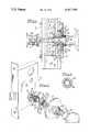
- FIG. 1represents an elevation of the edge of a door having fitted therein a mortise type lockset with inner and outer knobs, parts being broken away and parts being in section;
- FIG. 2represents an exploded perspective view of the elements comprising the invention.
- FIG. 3represents a detail elevation showing the inner surface of an alternative form of trim aligner.
- a door 11is mortised as indicated at 12 to receive the mortise lockset 13.
- Each side wall 14 of the lockset casehas openings in the customary locations and the walls of the case adjacent the latch hub 15 are thickened, as shown at 16, the holes 17 in the thickened portions being threaded.
- the case aligner 20is a double threaded bushing, its inner end portion 21 being threaded to engage in the hole 17 and its outer portion 22, of a slightly larger diameter, being threaded to receive the trim aligner. Between the portions 21 and 22 the case aligner is provided with an annular groove 23 in which the C-ring 24 is snapped.
- the case alignercould, alternatively, be formed with an integral flange in the position of the C-ring.
- the trim aligner 25is also in the form of a bushing, internally threaded at 26 to be screwed onto the portion 22 of the case aligner, externally threaded at 27 to receive the rose bushing and provided with a medially located annular collar or flange 28, the latter having oppositely disposed projections 29 defining openings in the form of radially open slots 30, for a purpose to be described below.
- the trim assemblyis completed by the rose 31, the rose bushing 32, the nylon spindle bushing 33, and spindle 34 and the knob 35, the knob being fixed on the spindle in the usual manner and being provided with a shoulder 36 adapted to fit freely within the nylon spindle bushing 33.
- the term "knob"is intended to include a handle or the like.
- the case aligner 20is screwed into the hole 17 to engage the C-ring 24 tightly against the surface of the case.
- the trim aligner 25is screwed on to the portion 22 of the case aligner to a point where the collar or flange 28 bears firmly against the surface of the door, as shown in FIG. 1 and a trim aligner screw 39 is placed in one of the slots 30 and screwed into the door, to prevent the trim aligner from unscrewing.
- the advancement of the trim aligner on the case aligneris determined by the thickness of the door material adjacent to the mortise.
- the spindle 34 and knob 35are assembled in the usual manner with the nylon bushing 33, rose bushing 32 and rose 31 loosely threaded on the spindle, which is then passed through the aligners 25 and 20, and into and through the hub 15.
- the rose 31is then fitted onto the trim aligner, the rose bushing 32 is screwed thereon, finger tight, to hold the rose against the door surface, and the nylon bushing 33 is force fitted into the trim aligner.
- the spindleis advanced through the hub 15 and out the opposite side of the door, through a corresponding assembly of elements, to be secured to a second knob 40 by means of the set screw 41, in a customary manner.
- the projections 29 and slots 30are eliminated, the collar or flange 45 being annular and provided on its inner face (toward the door surface) with surface irregularities 46 such as serrations, ridges or scoring, adapted to bite into the door surface when the aligner is screwed home, to an extent sufficient to prevent unscrewing when the assembly has been completed.
- the entire trim assemblyis supported and/or positioned in a rigid and positive manner in positions which are fixed relative to the case of the lockset and to the latch hub journaled therein.
- the nylon bushing 33is both a thrust and a circular bearing for the shoulder 36 on the knob, the knob and spindle being retained in accurate axial alignment with the axis of the hub, and the corresponding structure on the other side of the door results in the spindle being supported in fixed bearings spaced as far apart as possible, with the most advantageous lever arm. Any looseness or play between the knob and the spindle can have no effect on the alignment of the spindle with the hub.
Landscapes
- Engineering & Computer Science (AREA)
- Mechanical Engineering (AREA)
- Lock And Its Accessories (AREA)
Abstract
Description
This invention relates to trim alignment means for a mortise lock wherein the spindle is located in a bushing which is rigidly connected to the lock case in a position to hold the spindle in correct alignment with the hub of the lockset.
In door locks having a mortise type lockset it has been customary to journal the spindle, at its point of connection with a knob or handle, in a bushing which is mounted on a back plate (beneath the rose) which, in turn, is mounted on the door face by means of two or more screws. The axis of the bushing is aligned as accurately as possible with the axis of lockset hub and this alignment, whether correct or not, is maintained by the engagement of the screws in the door face. There is a substantial amount of play between the spindle and the hub, so that exact positioning of the back plate, with its axis corresponding with the hub axis, is difficult to achieve. When the back plate screws become loosened the entire trim assembly is free to wobble with considerable amplitude, causing the edge of the rose to scar the door surface.
It is accordingly an object of the present invention to provide trim alignment means wherein the bushing supporting the spindle at its point of connection to a knob or handle is connected rigidly to the case of the lockset.
It is a further object of the invention to provide a double threaded bushing, one end of which is screwed into the case, the other (outer) end being adapted to receive a trim aligner, on which the rose, rose bushing and spindle bushing may be mounted.
It is another object of the invention to provide means for stabilizing the trim aligner against loosening.
It is a still further object of the invention to provide certain improvements in the form, construction and arrangement of the several parts whereby the above named and other objects may effectively be attained.
The invention accordingly comprises an article of manufacture possessing the features, properties, and the relation of elements which will be exemplified in the article hereinafter described, and the scope of the invention will be indicated in the claims.
A practical embodiment of the invention is shown in the accompanying drawing wherein:
FIG. 1 represents an elevation of the edge of a door having fitted therein a mortise type lockset with inner and outer knobs, parts being broken away and parts being in section;
FIG. 2 represents an exploded perspective view of the elements comprising the invention; and
FIG. 3 represents a detail elevation showing the inner surface of an alternative form of trim aligner.
Referring to the drawing, a door 11 is mortised as indicated at 12 to receive themortise lockset 13. Eachside wall 14 of the lockset case has openings in the customary locations and the walls of the case adjacent thelatch hub 15 are thickened, as shown at 16, theholes 17 in the thickened portions being threaded.
The case aligner 20 is a double threaded bushing, its inner end portion 21 being threaded to engage in thehole 17 and itsouter portion 22, of a slightly larger diameter, being threaded to receive the trim aligner. Between theportions 21 and 22 the case aligner is provided with an annular groove 23 in which the C-ring 24 is snapped. The case aligner could, alternatively, be formed with an integral flange in the position of the C-ring.
Thetrim aligner 25 is also in the form of a bushing, internally threaded at 26 to be screwed onto theportion 22 of the case aligner, externally threaded at 27 to receive the rose bushing and provided with a medially located annular collar orflange 28, the latter having oppositely disposedprojections 29 defining openings in the form of radiallyopen slots 30, for a purpose to be described below.
The trim assembly is completed by therose 31, the rose bushing 32, the nylon spindle bushing 33, andspindle 34 and theknob 35, the knob being fixed on the spindle in the usual manner and being provided with ashoulder 36 adapted to fit freely within the nylon spindle bushing 33. The term "knob" is intended to include a handle or the like.
To assemble the parts described above, assuming thelockset 13 to be installed in the door as shown in FIG. 1, the case aligner 20 is screwed into thehole 17 to engage the C-ring 24 tightly against the surface of the case. Thetrim aligner 25 is screwed on to theportion 22 of the case aligner to a point where the collar orflange 28 bears firmly against the surface of the door, as shown in FIG. 1 and atrim aligner screw 39 is placed in one of theslots 30 and screwed into the door, to prevent the trim aligner from unscrewing. The advancement of the trim aligner on the case aligner is determined by the thickness of the door material adjacent to the mortise.
Thespindle 34 andknob 35 are assembled in the usual manner with the nylon bushing 33, rose bushing 32 and rose 31 loosely threaded on the spindle, which is then passed through thealigners 25 and 20, and into and through thehub 15.
Therose 31 is then fitted onto the trim aligner, the rose bushing 32 is screwed thereon, finger tight, to hold the rose against the door surface, and the nylon bushing 33 is force fitted into the trim aligner. With the parts 31-34 thus assembled, the spindle is advanced through thehub 15 and out the opposite side of the door, through a corresponding assembly of elements, to be secured to asecond knob 40 by means of theset screw 41, in a customary manner.
In the alternative form of trim aligner shown in FIG. 3, theprojections 29 andslots 30 are eliminated, the collar orflange 45 being annular and provided on its inner face (toward the door surface) withsurface irregularities 46 such as serrations, ridges or scoring, adapted to bite into the door surface when the aligner is screwed home, to an extent sufficient to prevent unscrewing when the assembly has been completed.
From the foregoing it will be apparent that the entire trim assembly is supported and/or positioned in a rigid and positive manner in positions which are fixed relative to the case of the lockset and to the latch hub journaled therein. The nylon bushing 33 is both a thrust and a circular bearing for theshoulder 36 on the knob, the knob and spindle being retained in accurate axial alignment with the axis of the hub, and the corresponding structure on the other side of the door results in the spindle being supported in fixed bearings spaced as far apart as possible, with the most advantageous lever arm. Any looseness or play between the knob and the spindle can have no effect on the alignment of the spindle with the hub.
While the arrangement of threaded portions as shown is considered to be preferable, it would be possible to thread theportion 22 internally and to substitute an external thread on the trim aligner in place ofinternal thread 26.
It will thus be seen that the objects set forth above, among those made apparent from the preceding description, are efficiently attained and, since certain changes may be made in the above article without departing from the spirit and scope of the invention, it is intended that all matter contained in the above description and shown in the accompanying drawing shall be interpreted as illustrative and not in a limiting sense.
Claims (9)
1. Lock trim alignment means for use with a mortise lock having a case and a latch hub and being installed in a door, comprising, a threaded opening in the lock case coaxial with the latch hub, a first bushing screwed into said threaded opening, a second bushing screwed onto the first bushing, a flange associated with the second bushing and projecting laterally in a position to engage a door surface adjacent said bushings, and a knob and spindle assembly journaled in said second bushing with the spindle aligned with the common axis of said bushings and hub.
2. Lock trim alignment means according to claim 1 wherein the first bushing is provided with a stop to limit its movement into said opening.
3. Lock trim alignment means according to claim 2 wherein the first bushing is formed medially with an annular groove and the stop is a C-ring fitted in said groove.
4. Lock trim alignment means according to claim 1 wherein the flange is integral with the second bushing.
5. Lock trim alignment means according to claim 4 wherein the flange is provided with openings to receive rotation preventing means.
6. Lock trim alignment means according to claim 4 wherein the flange is provided with surface irregularities adapted to engage the door surface.
7. Lock trim alignment means for use with a mortise lock having a case and a latch hub therein and being installed in a door, the lock case being provided with a threaded opening coaxial with the latch hub, the alignment means comprising a first bushing having first and second threaded portions and a stop and the first threaded portion being screwed in said threaded opening with said stop against the case, and a second bushing having two threaded portions with a flange therebetween, one threaded portion being adapted to be engaged with the second threaded portion of the first bushing, the flange being adapted to be engaged with a door surface adjacent said bushings when the second bushing is screwed onto the first bushing and the other threaded portion projecting axially outwardly beyond the plane of said flange and adapted to receive additional trim elements.
8. Lock trim alignment means according to claim 7 wherein the additional trim elements comprise a rose and a bushing screwed onto said other threaded portion to hold the rose firmly against the adjacent door surface.
9. Lock trim alignment means according to claim 7 wherein said axially projecting portion is provided with an antifriction bearing element adapted for a free fit with a complementary surface of a knob.
Priority Applications (1)
| Application Number | Priority Date | Filing Date | Title |
|---|---|---|---|
| US05/675,558US4067599A (en) | 1976-04-09 | 1976-04-09 | Trim alignment for mortise locks |
Applications Claiming Priority (1)
| Application Number | Priority Date | Filing Date | Title |
|---|---|---|---|
| US05/675,558US4067599A (en) | 1976-04-09 | 1976-04-09 | Trim alignment for mortise locks |
Publications (1)
| Publication Number | Publication Date |
|---|---|
| US4067599Atrue US4067599A (en) | 1978-01-10 |
Family
ID=24711013
Family Applications (1)
| Application Number | Title | Priority Date | Filing Date |
|---|---|---|---|
| US05/675,558Expired - LifetimeUS4067599A (en) | 1976-04-09 | 1976-04-09 | Trim alignment for mortise locks |
Country Status (1)
| Country | Link |
|---|---|
| US (1) | US4067599A (en) |
Cited By (32)
| Publication number | Priority date | Publication date | Assignee | Title |
|---|---|---|---|---|
| FR2449769A1 (en)* | 1979-02-26 | 1980-09-19 | Bezault Sa | Single side button operated door lock - has trim with fixed button on side opposite operating side to give cosmetic coherence |
| FR2466592A1 (en)* | 1979-10-01 | 1981-04-10 | Bezault Sa | Mounting of handle to door bearing plate - prevents axial play between handle and plate by retaining flanged metal bearing ring between them |
| US4405164A (en)* | 1980-09-12 | 1983-09-20 | Lint Christian L | Rattle-free door latch |
| US4453753A (en)* | 1982-06-04 | 1984-06-12 | Baldwin Hardware Manufacturing Corporation | Heat responsive door latch handle |
| US4640112A (en)* | 1983-08-08 | 1987-02-03 | R. R. Brink Locking Systems, Inc. | Security door knob and escutcheon |
| US4789191A (en)* | 1985-10-25 | 1988-12-06 | Carl F. Petersen A/S & Co. Vaerktoj, Mobel - Og Bygningsbeslag Ks | Centering device for securing and centering a door handle |
| US4877278A (en)* | 1989-02-17 | 1989-10-31 | Valley Harold J | Retainer for door handle |
| US5067758A (en)* | 1990-12-21 | 1991-11-26 | Tong-Lung Metal Industry Co., Ltd. | Lock handle assembly with limited angular movement |
| US5123682A (en)* | 1990-10-12 | 1992-06-23 | Emhart Inc. | Cylindrical lock assembly |
| US5149155A (en)* | 1991-06-14 | 1992-09-22 | Arrow Lock Manufacturing Company | Lever handle lock assembly |
| US5236235A (en)* | 1992-06-29 | 1993-08-17 | Chautauqua Hardware Company | Concealed screw rose mounting system |
| EP0738811A1 (en)* | 1995-04-08 | 1996-10-23 | KARL FLIETHER GmbH & Co. | Mortise lock |
| US5590555A (en)* | 1995-05-01 | 1997-01-07 | Best Lock Corporation | Anti-rotation mechanism for lockset chassis |
| US20030056556A1 (en)* | 2001-09-21 | 2003-03-27 | Park Dea San | Lever door lock device |
| US6616203B1 (en) | 2002-08-26 | 2003-09-09 | Corbin Russwin, Inc. | Door latch operator mount |
| US6802543B1 (en)* | 2002-10-25 | 2004-10-12 | Aaon, Inc. | Door handle |
| US6938445B2 (en) | 2003-03-26 | 2005-09-06 | Sargent Manufacturing Company | Mortise lock status indicator |
| US20050212306A1 (en)* | 2004-03-26 | 2005-09-29 | Sargent Manufacturing Company | Mortise lock integrated trim assembly with a retracting spindle |
| US20060131897A1 (en)* | 2004-12-17 | 2006-06-22 | The Steelworks Corporation | Door latch mounting bracket |
| US20060220397A1 (en)* | 2005-04-05 | 2006-10-05 | Ellis Philip C | Door handle assembly including auxiliary bearing and auxiliary bearing support for a door handle |
| US20100187839A1 (en)* | 2007-07-31 | 2010-07-29 | Sean Barlett | Handle assembly |
| US20100259053A1 (en)* | 2009-04-08 | 2010-10-14 | Cramer Randy S | Door handle attachment fixture |
| JP2013505384A (en)* | 2009-09-23 | 2013-02-14 | ウルフィチ−インダストリア デ フェラジェンス,ソシエダージ アノーニマ | Mounting configuration for door handles |
| US8544903B1 (en)* | 2009-07-14 | 2013-10-01 | Sargent Manufacturing Company | Roseless trim for architectural hardware |
| US20170350163A1 (en)* | 2016-06-02 | 2017-12-07 | Delta Lock Company, LLC | Interchangeable core lock assemblies |
| US10435914B2 (en) | 2016-04-14 | 2019-10-08 | Delta Lock Company, LLC | Interchangeable core lock assemblies |
| USD988835S1 (en) | 2021-05-10 | 2023-06-13 | Innovation Lock, Llc | Ratchet locking device |
| US11879269B2 (en) | 2021-05-10 | 2024-01-23 | Innovation Lock, Llc | Ratchet lock assemblies |
| US20240035312A1 (en)* | 2022-07-26 | 2024-02-01 | Innovation Lock, Llc | Drawer lock assemblies |
| US11976497B2 (en) | 2021-01-05 | 2024-05-07 | Innovation Lock, Llc | Drawer lock assemblies |
| EP4375456A1 (en)* | 2022-11-25 | 2024-05-29 | Griffwerk GmbH | Locking system for doors or windows |
| US12359470B2 (en) | 2022-05-27 | 2025-07-15 | Innovation Lock, Llc | Multi-axis latchbolt lock assembly |
Citations (4)
| Publication number | Priority date | Publication date | Assignee | Title |
|---|---|---|---|---|
| US109409A (en)* | 1870-11-22 | Improvement in roses for door-knobs | ||
| US297402A (en)* | 1884-04-22 | Latch knob attachment | ||
| US2846255A (en)* | 1954-06-28 | 1958-08-05 | Sargent & Co | Door locks |
| US2924480A (en)* | 1956-08-21 | 1960-02-09 | Yale & Towne Mfg Co | Mortise lock |
- 1976
- 1976-04-09USUS05/675,558patent/US4067599A/ennot_activeExpired - Lifetime
Patent Citations (4)
| Publication number | Priority date | Publication date | Assignee | Title |
|---|---|---|---|---|
| US109409A (en)* | 1870-11-22 | Improvement in roses for door-knobs | ||
| US297402A (en)* | 1884-04-22 | Latch knob attachment | ||
| US2846255A (en)* | 1954-06-28 | 1958-08-05 | Sargent & Co | Door locks |
| US2924480A (en)* | 1956-08-21 | 1960-02-09 | Yale & Towne Mfg Co | Mortise lock |
Cited By (40)
| Publication number | Priority date | Publication date | Assignee | Title |
|---|---|---|---|---|
| FR2449769A1 (en)* | 1979-02-26 | 1980-09-19 | Bezault Sa | Single side button operated door lock - has trim with fixed button on side opposite operating side to give cosmetic coherence |
| FR2466592A1 (en)* | 1979-10-01 | 1981-04-10 | Bezault Sa | Mounting of handle to door bearing plate - prevents axial play between handle and plate by retaining flanged metal bearing ring between them |
| US4405164A (en)* | 1980-09-12 | 1983-09-20 | Lint Christian L | Rattle-free door latch |
| US4453753A (en)* | 1982-06-04 | 1984-06-12 | Baldwin Hardware Manufacturing Corporation | Heat responsive door latch handle |
| US4640112A (en)* | 1983-08-08 | 1987-02-03 | R. R. Brink Locking Systems, Inc. | Security door knob and escutcheon |
| US4789191A (en)* | 1985-10-25 | 1988-12-06 | Carl F. Petersen A/S & Co. Vaerktoj, Mobel - Og Bygningsbeslag Ks | Centering device for securing and centering a door handle |
| US4877278A (en)* | 1989-02-17 | 1989-10-31 | Valley Harold J | Retainer for door handle |
| US5123682A (en)* | 1990-10-12 | 1992-06-23 | Emhart Inc. | Cylindrical lock assembly |
| US5067758A (en)* | 1990-12-21 | 1991-11-26 | Tong-Lung Metal Industry Co., Ltd. | Lock handle assembly with limited angular movement |
| US5149155A (en)* | 1991-06-14 | 1992-09-22 | Arrow Lock Manufacturing Company | Lever handle lock assembly |
| US5236235A (en)* | 1992-06-29 | 1993-08-17 | Chautauqua Hardware Company | Concealed screw rose mounting system |
| EP0738811A1 (en)* | 1995-04-08 | 1996-10-23 | KARL FLIETHER GmbH & Co. | Mortise lock |
| US5590555A (en)* | 1995-05-01 | 1997-01-07 | Best Lock Corporation | Anti-rotation mechanism for lockset chassis |
| US20030056556A1 (en)* | 2001-09-21 | 2003-03-27 | Park Dea San | Lever door lock device |
| US6616203B1 (en) | 2002-08-26 | 2003-09-09 | Corbin Russwin, Inc. | Door latch operator mount |
| US6802543B1 (en)* | 2002-10-25 | 2004-10-12 | Aaon, Inc. | Door handle |
| US6938445B2 (en) | 2003-03-26 | 2005-09-06 | Sargent Manufacturing Company | Mortise lock status indicator |
| US20050212306A1 (en)* | 2004-03-26 | 2005-09-29 | Sargent Manufacturing Company | Mortise lock integrated trim assembly with a retracting spindle |
| US7077437B2 (en) | 2004-03-26 | 2006-07-18 | Sargent Manufacturing Company | Mortise lock integrated trim assembly with a retracting spindle |
| US20060131897A1 (en)* | 2004-12-17 | 2006-06-22 | The Steelworks Corporation | Door latch mounting bracket |
| US20060220397A1 (en)* | 2005-04-05 | 2006-10-05 | Ellis Philip C | Door handle assembly including auxiliary bearing and auxiliary bearing support for a door handle |
| US20080084075A1 (en)* | 2005-04-05 | 2008-04-10 | Newfrey, Llc. | Door handle assembly including auxiliary bearing and auxiliary bearing support for a door handle |
| US7347462B2 (en)* | 2005-04-05 | 2008-03-25 | Newfrey, Llc | Door handle assembly including auxiliary bearing and auxiliary bearing support for a door handle |
| US20100187839A1 (en)* | 2007-07-31 | 2010-07-29 | Sean Barlett | Handle assembly |
| US20100259053A1 (en)* | 2009-04-08 | 2010-10-14 | Cramer Randy S | Door handle attachment fixture |
| US8210581B2 (en)* | 2009-04-08 | 2012-07-03 | Newfrey, Llc | Door handle attachment fixture |
| US8544903B1 (en)* | 2009-07-14 | 2013-10-01 | Sargent Manufacturing Company | Roseless trim for architectural hardware |
| US9062475B1 (en)* | 2009-07-14 | 2015-06-23 | Sargent Manufacturing Company | Roseless trim for architectural hardware |
| JP2013505384A (en)* | 2009-09-23 | 2013-02-14 | ウルフィチ−インダストリア デ フェラジェンス,ソシエダージ アノーニマ | Mounting configuration for door handles |
| US10435914B2 (en) | 2016-04-14 | 2019-10-08 | Delta Lock Company, LLC | Interchangeable core lock assemblies |
| US20170350163A1 (en)* | 2016-06-02 | 2017-12-07 | Delta Lock Company, LLC | Interchangeable core lock assemblies |
| US10724276B2 (en)* | 2016-06-02 | 2020-07-28 | Delta Lock Company, LLC | Interchangeable core lock assemblies |
| US11603680B2 (en) | 2016-06-02 | 2023-03-14 | Innovation Lock, Llc | Interchangeable core lock assemblies |
| US11732507B2 (en) | 2016-06-02 | 2023-08-22 | Innovation Lock, Llc | Interchangeable core lock assemblies |
| US11976497B2 (en) | 2021-01-05 | 2024-05-07 | Innovation Lock, Llc | Drawer lock assemblies |
| USD988835S1 (en) | 2021-05-10 | 2023-06-13 | Innovation Lock, Llc | Ratchet locking device |
| US11879269B2 (en) | 2021-05-10 | 2024-01-23 | Innovation Lock, Llc | Ratchet lock assemblies |
| US12359470B2 (en) | 2022-05-27 | 2025-07-15 | Innovation Lock, Llc | Multi-axis latchbolt lock assembly |
| US20240035312A1 (en)* | 2022-07-26 | 2024-02-01 | Innovation Lock, Llc | Drawer lock assemblies |
| EP4375456A1 (en)* | 2022-11-25 | 2024-05-29 | Griffwerk GmbH | Locking system for doors or windows |
Similar Documents
| Publication | Publication Date | Title |
|---|---|---|
| US4067599A (en) | Trim alignment for mortise locks | |
| US6364383B1 (en) | Easy-to-install door lock with burglar-proof effect for outside rose assembly | |
| US5010749A (en) | Locking device for an auxiliary lock | |
| US4343502A (en) | Doorknob construction | |
| JPS5825831B2 (en) | furniture hinges | |
| US5335950A (en) | Door lockset with spindle bearing | |
| US5029914A (en) | Fitting with a handle for operating the lock follower of a lock fitted in a door or the like | |
| GB2103275A (en) | A door handle assembly | |
| US2811384A (en) | Rose for mortise lock | |
| US861421A (en) | Combined lock and latch. | |
| GB2077344A (en) | Lock | |
| US3508777A (en) | Door latch apparatus | |
| US2924480A (en) | Mortise lock | |
| US20040123427A1 (en) | Adjustable handle assembly for a lock | |
| US2697342A (en) | Lock mechanism | |
| US4884835A (en) | Lever spindle spring cage | |
| US2303790A (en) | Door lock | |
| US211853A (en) | Improvement in latches | |
| JPH0332205Y2 (en) | ||
| US2864642A (en) | Door knob construction | |
| US862230A (en) | Combined lock and latch. | |
| JPS6025485Y2 (en) | Door grip mechanism | |
| US2450449A (en) | Door lock | |
| JPH0239003Y2 (en) | ||
| US1058530A (en) | Door-knob and shank. |
Legal Events
| Date | Code | Title | Description |
|---|---|---|---|
| AS | Assignment | Owner name:KIDDE, INC. Free format text:CHANGE OF NAME;ASSIGNOR:WALTER KIDDE & COMPANY, INC.;REEL/FRAME:004056/0845 Effective date:19820830 Owner name:KIDDE, INC., NEW YORK Free format text:CHANGE OF NAME;ASSIGNOR:WALTER KIDDE & COMPANY, INC.;REEL/FRAME:004056/0845 Effective date:19820830 | |
| AS | Assignment | Owner name:SARGENT MANUFACTURING COMPANY, 100 SARGENT DRIVE, Free format text:ASSIGNMENT OF ASSIGNORS INTEREST.;ASSIGNOR:KIDDE, INC., A CORP. OF DE.;REEL/FRAME:004589/0616 Effective date:19860206 Owner name:KIDDE, INC. Free format text:CHANGE OF NAME;ASSIGNOR:WALTER KIDDE & COMPANY, INC.;REEL/FRAME:004589/0612 Effective date:19820830 |