US4066282A - Positive tubing release coupling - Google Patents
Positive tubing release couplingDownload PDFInfo
- Publication number
- US4066282A US4066282AUS05/691,384US69138476AUS4066282AUS 4066282 AUS4066282 AUS 4066282AUS 69138476 AUS69138476 AUS 69138476AUS 4066282 AUS4066282 AUS 4066282A
- Authority
- US
- United States
- Prior art keywords
- fingers
- male
- marginal
- female
- another
- Prior art date
- Legal status (The legal status is an assumption and is not a legal conclusion. Google has not performed a legal analysis and makes no representation as to the accuracy of the status listed.)
- Expired - Lifetime
Links
- 230000008878couplingEffects0.000titleclaimsabstractdescription32
- 238000010168coupling processMethods0.000titleclaimsabstractdescription32
- 238000005859coupling reactionMethods0.000titleclaimsabstractdescription32
- 239000012530fluidSubstances0.000claimsdescription11
- 230000000295complement effectEffects0.000claimsdescription2
- 238000004519manufacturing processMethods0.000description5
- 239000002360explosiveSubstances0.000description3
- 238000000926separation methodMethods0.000description2
- 241000191291Abies albaSpecies0.000description1
- 238000003801millingMethods0.000description1
Images

Classifications
- E—FIXED CONSTRUCTIONS
- E21—EARTH OR ROCK DRILLING; MINING
- E21B—EARTH OR ROCK DRILLING; OBTAINING OIL, GAS, WATER, SOLUBLE OR MELTABLE MATERIALS OR A SLURRY OF MINERALS FROM WELLS
- E21B17/00—Drilling rods or pipes; Flexible drill strings; Kellies; Drill collars; Sucker rods; Cables; Casings; Tubings
- E21B17/02—Couplings; joints
- E21B17/04—Couplings; joints between rod or the like and bit or between rod and rod or the like
- E21B17/046—Couplings; joints between rod or the like and bit or between rod and rod or the like with ribs, pins, or jaws, and complementary grooves or the like, e.g. bayonet catches
- E—FIXED CONSTRUCTIONS
- E21—EARTH OR ROCK DRILLING; MINING
- E21B—EARTH OR ROCK DRILLING; OBTAINING OIL, GAS, WATER, SOLUBLE OR MELTABLE MATERIALS OR A SLURRY OF MINERALS FROM WELLS
- E21B17/00—Drilling rods or pipes; Flexible drill strings; Kellies; Drill collars; Sucker rods; Cables; Casings; Tubings
- E21B17/02—Couplings; joints
- E21B17/04—Couplings; joints between rod or the like and bit or between rod and rod or the like
- E21B17/06—Releasing-joints, e.g. safety joints
- E—FIXED CONSTRUCTIONS
- E21—EARTH OR ROCK DRILLING; MINING
- E21B—EARTH OR ROCK DRILLING; OBTAINING OIL, GAS, WATER, SOLUBLE OR MELTABLE MATERIALS OR A SLURRY OF MINERALS FROM WELLS
- E21B43/00—Methods or apparatus for obtaining oil, gas, water, soluble or meltable materials or a slurry of minerals from wells
- E21B43/11—Perforators; Permeators
- E21B43/116—Gun or shaped-charge perforators
Definitions
- This inventionrelates to downhole tools, and specifically to a fluid conducting, releasable coupling apparatus which can be interposed within a tool string for subsequently parting the string at a predetermined location along its length by manipulation of the invention with a wireline fishing tool.
- the tool of the present inventionincludes a female member which telescopingly receives a male member therewithin.
- the telescoping marginal end portion of the male and female memberscooperate together to form a load transferring member which is held together by a releasing member.
- the releasing member and load transferring membersare concentrically arranged relative to one another so that a fishing tool can engage and move the releasing member, thereby allowing the male and female load transferring members to telescopingly move apart from one another.
- a marginal interior portion of the female memberis threaded, while a marginal outer surface of the male member is provided with a complementary threaded area.
- the threaded area of the male memberis in the form of a plurality of elongated fingers and are formed by a series of radially spaced, longitudinal cutouts which leave radially spaced, longitudinally disposed lands. The fingers may be urged radially inwardly towards one another to thereby permit the coacting threaded surfaces to move respective to one another, so that the male and female members axially move apart upon removal of the releasing member.
- a primary purpose of this inventionis the provision of a fluid conducting releasable coupling which ties together a tubing string in a releasable manner.
- Another object of the inventionis to provide a wire-line actuated releasable coupling apparatus.
- a further object of this inventionis to provide a releasable coupling member having an internal member which is axially movable to cause one part of the coupling to be released from another part of the coupling.
- a still further object of the inventionis to provide a releasable coupling assembly having an unobstructed axial passageway formed therethrough, and which transfers torque through a tubing string.
- Still another object of the inventionis the provision of a releasable coupling which is a sealed flow passageway and which can transfer both tension and torque.
- An additional object of this inventionis to disclose and provide a releasable coupling which can be parted in a more reliable and positive manner than was heretofore realized.
- FIG. 1is a part schematical, part diagrammatical representation of a borehole formed within the earth, with apparatus made in accordance with the present invention being disposed therewithin;
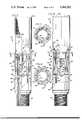
- FIG. 2is an enlarged, exploded, perspective view of part of the apparatus disclosed in FIG. 1;
- FIGS. 3 and 4are enlarged, longitudinal, part cross-sectional representations of part of the apparatus disclosed in FIGS. 1 and 2, with some parts being removed therefrom; and,
- FIGS. 5 and 6, respectively,are cross-sectional views taken along lines 5--5 of FIG. 3 and 6--6 of FIG. 4, respectively.
- FIG. 1there is disclosed a wellhead or christmas tree 10 in fluid communication with an oil producing strata 11 by means of borehole 12 which extends through the surface of the ground 14 so that production fluid can flow uphole through a production tubing 15.
- a packer device 16separates the upper and lower bore-hole annulus and receives the production tubing therethrough.
- the production tubingcontinues at 17 and 18 in order to connect a vent string 19 to a releasable coupling 20 made in accordance with the present invention.
- Perforating gun 21is connected to the releasable coupling and can be separated from the vent string at any subsequent time by manipulating the releasable coupling of this invention with a wireline actuated fishing tool of a type known to those skilled in the art.
- FIGS. 2-6disclose the details of the releasable coupling seen at 20 in FIG. 1.
- the couplingcomprises a pair of load transferring members which include a female sub 22 having a lower end portion 24, and an upper end portion 26, often called the box end.
- the female couplinghas an interior lower marginal portion 28 spaced from a medial, marginal, smooth bore 29 by a threaded marginal length 30. The threads extend from 32 to 33.
- the upper marginal end of the female subis provided with threads 34 which commence near end portion 26 and terminate at 35.
- Male member 36forms the remaining load transferring member and is provided with a circumferentially extending shoulder 38 which abuttingly engages the lower terminal end 24 of the female member.
- the lower marginal end of the male subis threaded to form the pin end 40, thereby enabling the apparatus to be interposed within an ordinary string of production tubing or the like.
- the telescoping marginal end of the male memberis threaded at 42.
- a circumferentially extending groove 44is formed within the reduced constant diameter portion 46 which separates the threads 42 from the shoulder 38, thereby providing an adequate marginal length of surface on the male member for accommodating the illustrated seal thereon.
- a plurality of radially spaced-apart lands 48extend from the constant diameter portion 46 and are defined by spaced, parallel sidewalls 50 and 52. The lands are joined together at 54. The threaded area commences at 56 in spaced relationship to the joinder member 54, and terminates at the terminal end 60 of the male member.
- cutouts 62are formed in radially spaced relationship about the male member, with the cutouts terminating at 54 to thereby form a series of longitudinally aligned, radially spaced, upwardly opening grooves which define the before mentioned fingers.
- a releasing member 64preferably includes an upper conical surface which downwardly converges into a central passageway.
- the passagewayis of constant i.d. and terminates at the lower end 68 thereof.
- the large o.d. portion 70has a circumferentially extending groove 72 circumferentially formed therein for receiving the illustrated seal therewithin.
- Shoulder 74 of the releasing memberis formed between the large o.d. 70 and small o.d. 77 of the member. The shoulder is received in seated relationship against the upper terminal end 60 of the fingers in the illustrated manner of FIGS. 3 and 4.
- Surface 80 of the conical portion of the releasing memberis arranged whereby there is no likelihood of inadvertent engagement with tool strings which may be lowered down through the releasing member.
- the apparatus of the present inventionis preferably arranged in the manner of FIGS. 2, 3, and 4, although it would be possible to use the releasing member in the inverted configuration.
- the configuration of the releasing member 64would preferably be modified so that the relationship of the conical surface 80 and the end 68 is reversed.
- the male memberis fabricated by turning the threaded area 58 prior to milling the cutouts 62 therein to thereby provide the individual fingers with a well-defined threaded area.
- the threaded areais calculated whereby the pitch and depth, as well as the number of threads, are of a value which is at least equal to the breaking strength of the tubing 18.
- the resultant structure provided by the individual fingersmust likewise have a breaking strength equivalent to the breaking strength of the tubing string 15 or 18.
- Those skilled in the artcan calculate the wall thickness of the fingers and the permissible cutout area, as well as the configuration, depth, and number of threads.
- thread area 58is intended to include individual, circumferentially spaced-apart grooves, as well as a continuous thread which extends from 60 to 56.
- the apparatusis assembled by screwing the male and female members together with a suitable gasket being placed within the annular groove 44 so that the resultant structure provides a sealed fluid coupling having a pin end at 40 and box end at 26 in the conventional manner of a tool string sub.
- the releasing member 64is next provided with the illustrated resilient seal and slidably placed into the illustrated position seen in FIGS. 3 and 5.
- the individual fingersare urged outwardly into engagement with the threaded area formed on the female member and consequently, the two members are effectively tied together in a positive manner.
- the releasable couplingis interposed within a tool string, such as exemplified by FIG. 1, and when it is desired to release a lower maginal length 18 of the string from an upper marginal length 17, a fishing tool can be run downhole in the usual manner until the fishing tool passes through the releasing member.
- the wireline actuated fishing toolis picked up, the lower end 68 of the releasing member is engaged by the tool and the releasing member is moved uphole out of engagement with the fingers.
- Upper end 66 of the releasing membergenerally will engage the lower, circumferentially extending shoulder presented by the tubing string 17 to thereby form a positive stop means which abuttingly engages the upper shoulder of the releasing member.
- the foregoing manipulative actionremoves the outward force exerted upon the individual fingers, thereby enabling the fingers to yieldably move towards one another so that the threaded surfaces at 42 and 58 can move laterally of one another, thereby enabling the male member to telescope or slide apart from the female member.
- This actionreleases the lower male member, along with everything connected thereto so that the lower tubing string 18, along with the gun 21, is dropped to the bottom of the borehole, while the female member remains connected to the upper tubing string 17.
- An important feature of the present inventionlies in providing an elongated plurality of fingers having a cutout which extends well below the threads 58 to thereby present a finger length which extends from 54 up to the beginning of the threaded area at 56.
- This feature of the inventionprovides an elongated finger having a threaded outer marginal end portion spaced from a main body portion such that the threaded area of the individual fingers can be resiliently urged towards one another by the action of the male and female members being pulled apart axially from one another.
- the pitch of the threads 58provides a wedgelike action which maintains the members joined together so long as the releasable member maintains the coacting threads interlocked with one another; and, when the releasing member is removed, the resultant force causes the individual fingers to be resiliently urged towards one another, thereby enabling the coacting threaded surfaces to move laterally respective to one another, so that the male and female members are parted.
- the fishing toolcan be removed from the apparatus in any number of different manners known to those skilled in the art of fishing tools.
- the O-ring placed within groove 72 of the releasing memberprevents inadvertent movement while a trip is being made through the releasable coupling with various different tools.
Landscapes
- Engineering & Computer Science (AREA)
- Life Sciences & Earth Sciences (AREA)
- Geology (AREA)
- Mining & Mineral Resources (AREA)
- Physics & Mathematics (AREA)
- Environmental & Geological Engineering (AREA)
- Fluid Mechanics (AREA)
- General Life Sciences & Earth Sciences (AREA)
- Geochemistry & Mineralogy (AREA)
- Mechanical Engineering (AREA)
- Earth Drilling (AREA)
Abstract
Description
Claims (12)
Priority Applications (1)
| Application Number | Priority Date | Filing Date | Title |
|---|---|---|---|
| US05/691,384US4066282A (en) | 1974-10-23 | 1976-06-01 | Positive tubing release coupling |
Applications Claiming Priority (2)
| Application Number | Priority Date | Filing Date | Title |
|---|---|---|---|
| US05/517,391US3966236A (en) | 1974-10-23 | 1974-10-23 | Releasable coupling |
| US05/691,384US4066282A (en) | 1974-10-23 | 1976-06-01 | Positive tubing release coupling |
Related Parent Applications (1)
| Application Number | Title | Priority Date | Filing Date |
|---|---|---|---|
| US05/517,391Continuation-In-PartUS3966236A (en) | 1974-10-23 | 1974-10-23 | Releasable coupling |
Publications (1)
| Publication Number | Publication Date |
|---|---|
| US4066282Atrue US4066282A (en) | 1978-01-03 |
Family
ID=42736161
Family Applications (1)
| Application Number | Title | Priority Date | Filing Date |
|---|---|---|---|
| US05/691,384Expired - LifetimeUS4066282A (en) | 1974-10-23 | 1976-06-01 | Positive tubing release coupling |
Country Status (1)
| Country | Link |
|---|---|
| US (1) | US4066282A (en) |
Cited By (26)
| Publication number | Priority date | Publication date | Assignee | Title |
|---|---|---|---|---|
| US4364587A (en)* | 1979-08-27 | 1982-12-21 | Samford Travis L | Safety joint |
| US4423889A (en) | 1980-07-29 | 1984-01-03 | Dresser Industries, Inc. | Well-tubing expansion joint |
| US4554981A (en)* | 1983-08-01 | 1985-11-26 | Hughes Tool Company | Tubing pressurized firing apparatus for a tubing conveyed perforating gun |
| US4601492A (en)* | 1982-10-20 | 1986-07-22 | Geo Vann, Inc. | Releasable coupling |
| US4635733A (en)* | 1982-06-07 | 1987-01-13 | Halliburton Company | Gun firing system using fluid filled pressure balance tubing |
| US4765409A (en)* | 1986-10-02 | 1988-08-23 | Western Atlas International, Inc. | Automatic separation device for use with wireline conveyed perforating gun |
| US4862957A (en)* | 1985-09-11 | 1989-09-05 | Dowell Schlumberger Incorporated | Packer and service tool assembly |
| US4913053A (en)* | 1986-10-02 | 1990-04-03 | Western Atlas International, Inc. | Method of increasing the detonation velocity of detonating fuse |
| US5156213A (en)* | 1991-05-03 | 1992-10-20 | Halliburton Company | Well completion method and apparatus |
| US5366014A (en)* | 1993-11-04 | 1994-11-22 | Halliburton Company | Method and apparatus for perforating a well using a modular perforating gun system |
| US5398760A (en)* | 1993-10-08 | 1995-03-21 | Halliburton Company | Methods of perforating a well using coiled tubing |
| US5423382A (en)* | 1993-11-10 | 1995-06-13 | Dresser Industries, Inc. | Apparatus for releasing perforating gun equipment from a well casing |
| US5529127A (en)* | 1995-01-20 | 1996-06-25 | Halliburton Company | Apparatus and method for snubbing tubing-conveyed perforating guns in and out of a well bore |
| US5875156A (en)* | 1993-07-09 | 1999-02-23 | Hitachi, Ltd. | Playback system for an optical disc representing a character or a graphic pattern formed by specified pit patterns |
| US6425443B1 (en) | 2000-11-20 | 2002-07-30 | Schlumberger Technology Corporation | Pressure compensated disconnect system and method |
| US20050183860A1 (en)* | 2004-02-24 | 2005-08-25 | 789047 Alberta Ltd. | Wireline coupler |
| US7108296B2 (en)* | 2002-09-17 | 2006-09-19 | Itt Manufacturing Enterprises, Inc. | Fluid quick connector for threaded fluid components |
| US7568737B2 (en) | 2006-09-22 | 2009-08-04 | Eaton Corporation | Male coupling for connecting to female threaded coupling |
| US20110110746A1 (en)* | 2009-11-11 | 2011-05-12 | Dwight Smith | Fast-acting collapsible fastener |
| US20120305319A1 (en)* | 2011-06-02 | 2012-12-06 | Baker Hughes Incorporated | Safety joint with indicating feature |
| US8727019B2 (en)* | 2012-03-06 | 2014-05-20 | Halliburton Energy Services, Inc. | Safety joint with non-rotational actuation |
| US8733451B2 (en) | 2012-03-06 | 2014-05-27 | Halliburton Energy Services, Inc. | Locking safety joint for use in a subterranean well |
| CN103912231A (en)* | 2014-04-09 | 2014-07-09 | 中国石油化工股份有限公司 | Drill rod male-thread fisher |
| US8783370B2 (en) | 2012-03-06 | 2014-07-22 | Halliburton Energy Services, Inc. | Deactivation of packer with safety joint |
| US10329850B2 (en)* | 2016-08-08 | 2019-06-25 | Onesubsea Ip Uk Limited | Releasable locking mechanism |
| US20250003299A1 (en)* | 2023-06-30 | 2025-01-02 | Toby Scott Baudoin | Safety separation apparatus and method |
Citations (6)
| Publication number | Priority date | Publication date | Assignee | Title |
|---|---|---|---|---|
| US2409811A (en)* | 1941-04-04 | 1946-10-22 | Guiberson Corp | Setting and releasing tool |
| US2532686A (en)* | 1945-09-18 | 1950-12-05 | Ware Cecil | Safety joint |
| US2737248A (en)* | 1950-07-10 | 1956-03-06 | Baker Oil Tools Inc | Nonrotary threaded coupling |
| US3071188A (en)* | 1958-10-29 | 1963-01-01 | Otis Eng Co | Remotely controlled latch for well tools |
| US3136366A (en)* | 1958-08-22 | 1964-06-09 | Brown | Coupling devices |
| US3148894A (en)* | 1958-06-26 | 1964-09-15 | Otis Eng Co | Well tools |
- 1976
- 1976-06-01USUS05/691,384patent/US4066282A/ennot_activeExpired - Lifetime
Patent Citations (6)
| Publication number | Priority date | Publication date | Assignee | Title |
|---|---|---|---|---|
| US2409811A (en)* | 1941-04-04 | 1946-10-22 | Guiberson Corp | Setting and releasing tool |
| US2532686A (en)* | 1945-09-18 | 1950-12-05 | Ware Cecil | Safety joint |
| US2737248A (en)* | 1950-07-10 | 1956-03-06 | Baker Oil Tools Inc | Nonrotary threaded coupling |
| US3148894A (en)* | 1958-06-26 | 1964-09-15 | Otis Eng Co | Well tools |
| US3136366A (en)* | 1958-08-22 | 1964-06-09 | Brown | Coupling devices |
| US3071188A (en)* | 1958-10-29 | 1963-01-01 | Otis Eng Co | Remotely controlled latch for well tools |
Cited By (32)
| Publication number | Priority date | Publication date | Assignee | Title |
|---|---|---|---|---|
| US4364587A (en)* | 1979-08-27 | 1982-12-21 | Samford Travis L | Safety joint |
| US4423889A (en) | 1980-07-29 | 1984-01-03 | Dresser Industries, Inc. | Well-tubing expansion joint |
| US4635733A (en)* | 1982-06-07 | 1987-01-13 | Halliburton Company | Gun firing system using fluid filled pressure balance tubing |
| US4601492A (en)* | 1982-10-20 | 1986-07-22 | Geo Vann, Inc. | Releasable coupling |
| US4554981A (en)* | 1983-08-01 | 1985-11-26 | Hughes Tool Company | Tubing pressurized firing apparatus for a tubing conveyed perforating gun |
| US4862957A (en)* | 1985-09-11 | 1989-09-05 | Dowell Schlumberger Incorporated | Packer and service tool assembly |
| US4765409A (en)* | 1986-10-02 | 1988-08-23 | Western Atlas International, Inc. | Automatic separation device for use with wireline conveyed perforating gun |
| US4913053A (en)* | 1986-10-02 | 1990-04-03 | Western Atlas International, Inc. | Method of increasing the detonation velocity of detonating fuse |
| US5156213A (en)* | 1991-05-03 | 1992-10-20 | Halliburton Company | Well completion method and apparatus |
| AU647709B2 (en)* | 1991-05-03 | 1994-03-24 | Halliburton Company | Well completion method and apparatus |
| US5303772A (en)* | 1991-05-03 | 1994-04-19 | Halliburton Company | Well completion apparatus |
| US5875156A (en)* | 1993-07-09 | 1999-02-23 | Hitachi, Ltd. | Playback system for an optical disc representing a character or a graphic pattern formed by specified pit patterns |
| US5398760A (en)* | 1993-10-08 | 1995-03-21 | Halliburton Company | Methods of perforating a well using coiled tubing |
| US5366014A (en)* | 1993-11-04 | 1994-11-22 | Halliburton Company | Method and apparatus for perforating a well using a modular perforating gun system |
| US5423382A (en)* | 1993-11-10 | 1995-06-13 | Dresser Industries, Inc. | Apparatus for releasing perforating gun equipment from a well casing |
| US5529127A (en)* | 1995-01-20 | 1996-06-25 | Halliburton Company | Apparatus and method for snubbing tubing-conveyed perforating guns in and out of a well bore |
| US6425443B1 (en) | 2000-11-20 | 2002-07-30 | Schlumberger Technology Corporation | Pressure compensated disconnect system and method |
| US7108296B2 (en)* | 2002-09-17 | 2006-09-19 | Itt Manufacturing Enterprises, Inc. | Fluid quick connector for threaded fluid components |
| US20050183860A1 (en)* | 2004-02-24 | 2005-08-25 | 789047 Alberta Ltd. | Wireline coupler |
| US7353868B2 (en)* | 2004-02-24 | 2008-04-08 | 789047 Alberta Ltd. | Wireline coupler |
| US7568737B2 (en) | 2006-09-22 | 2009-08-04 | Eaton Corporation | Male coupling for connecting to female threaded coupling |
| US8342787B2 (en)* | 2009-11-11 | 2013-01-01 | Zipnut Technology, Llc | Fast-acting collapsible fastener |
| US20110110746A1 (en)* | 2009-11-11 | 2011-05-12 | Dwight Smith | Fast-acting collapsible fastener |
| US20120305319A1 (en)* | 2011-06-02 | 2012-12-06 | Baker Hughes Incorporated | Safety joint with indicating feature |
| US8727019B2 (en)* | 2012-03-06 | 2014-05-20 | Halliburton Energy Services, Inc. | Safety joint with non-rotational actuation |
| US8733451B2 (en) | 2012-03-06 | 2014-05-27 | Halliburton Energy Services, Inc. | Locking safety joint for use in a subterranean well |
| US8783370B2 (en) | 2012-03-06 | 2014-07-22 | Halliburton Energy Services, Inc. | Deactivation of packer with safety joint |
| US9587451B2 (en) | 2012-03-06 | 2017-03-07 | Halliburton Energy Services, Inc. | Deactivation of packer with safety joint |
| CN103912231A (en)* | 2014-04-09 | 2014-07-09 | 中国石油化工股份有限公司 | Drill rod male-thread fisher |
| US10329850B2 (en)* | 2016-08-08 | 2019-06-25 | Onesubsea Ip Uk Limited | Releasable locking mechanism |
| US20250003299A1 (en)* | 2023-06-30 | 2025-01-02 | Toby Scott Baudoin | Safety separation apparatus and method |
| US12312883B2 (en)* | 2023-06-30 | 2025-05-27 | Toby Scott Baudoin | Safety separation apparatus and method |
Similar Documents
| Publication | Publication Date | Title |
|---|---|---|
| US4066282A (en) | Positive tubing release coupling | |
| US4601492A (en) | Releasable coupling | |
| US4898239A (en) | Retrievable bridge plug | |
| US3966236A (en) | Releasable coupling | |
| US7591305B2 (en) | Patriot retrievable production packer | |
| US3871448A (en) | Packer actuated vent assembly | |
| US4497368A (en) | Hanger mechanism | |
| US2715441A (en) | Bridging plug | |
| US3095926A (en) | Apparatus for recovering objects in a well | |
| US3990510A (en) | Releasable well anchor tool | |
| US5085479A (en) | Vertically manipulated ratchet fishing tool | |
| US6880642B1 (en) | Well abandonment plug | |
| US2734581A (en) | bonner | |
| GB2124275A (en) | Hanger mechanism | |
| US3667543A (en) | Retrievable well packer | |
| US3834472A (en) | Jarring accelerator | |
| US3454089A (en) | Bridging plug with pressure relief means and mandrel latch | |
| US4098335A (en) | Dual string tubing hanger and running and setting tool therefor | |
| US4657084A (en) | Twin seal well packer | |
| GB2402955A (en) | Hydraulically released overshot tool | |
| US6173786B1 (en) | Pressure-actuated running tool | |
| US4513822A (en) | Anchor seal assembly | |
| US3198254A (en) | Method and apparatus for completing wells | |
| US2999543A (en) | Parallel tubular string apparatus for well bores | |
| US4600058A (en) | Equipment insert and method |
Legal Events
| Date | Code | Title | Description |
|---|---|---|---|
| AS | Assignment | Owner name:GEO VANN, INC. A CORP. OF NEW MEXICO Free format text:ASSIGNMENT OF ASSIGNORS INTEREST. EFFECTIVE. 9-21-77;ASSIGNOR:VANN, ROY R.;REEL/FRAME:003950/0314 Effective date:19820217 | |
| AS | Assignment | Owner name:GEO INTERNATIONAL CORPORATION, 1 LANDMARK SQ., STA Free format text:ASSIGNMENT OF ASSIGNORS INTEREST.;ASSIGNOR:PEABODY INTERNATIONAL CORPORATION;REEL/FRAME:004231/0865 Effective date:19840229 Owner name:GEO VANN, INC., 16350 PARK TEN PLACE DRIVE, HOUSTO Free format text:ASSIGNMENT OF ASSIGNORS INTEREST.;ASSIGNOR:GEO INTERNATIONAL CORPORATION;REEL/FRAME:004231/0869 Effective date:19840229 Owner name:PEABODY INTERNATIONAL CORPORATION, GALION, OH A DE Free format text:ASSIGNMENT OF ASSIGNORS INTEREST.;ASSIGNOR:VANN, ROY R, SR.;REEL/FRAME:004231/0873 Effective date:19770921 Owner name:GEO INTERNATIONAL CORPORATION, CONNECTICUT Free format text:ASSIGNMENT OF ASSIGNORS INTEREST;ASSIGNOR:PEABODY INTERNATIONAL CORPORATION;REEL/FRAME:004231/0865 Effective date:19840229 | |
| AS | Assignment | Owner name:GEO INTERNATIONAL CORPORATION, A CORP. OF DE. Free format text:ASSIGNMENT OF ASSIGNORS INTEREST.;ASSIGNOR:PEABODY INTERNATIONAL CORPORATION;REEL/FRAME:004555/0052 Effective date:19850928 Owner name:GEO INTERNATIONAL CORPORATION, CONNECTICUT Free format text:ASSIGNMENT OF ASSIGNORS INTEREST;ASSIGNOR:PEABODY INTERNATIONAL CORPORATION;REEL/FRAME:004555/0052 Effective date:19850928 | |
| AS | Assignment | Owner name:VANN SYSTEMS INC. Free format text:CHANGE OF NAME;ASSIGNOR:GEO VANN, INC.;REEL/FRAME:004606/0291 Effective date:19851015 Owner name:HALLIBURTON COMPANY Free format text:MERGER;ASSIGNOR:VANN SYSTEMS, INC.;REEL/FRAME:004606/0300 Effective date:19851205 Owner name:VANN SYSTEMS INC.,STATELESS Free format text:CHANGE OF NAME;ASSIGNOR:GEO VANN, INC.;REEL/FRAME:004606/0291 Effective date:19851015 Owner name:HALLIBURTON COMPANY,STATELESS Free format text:MERGER;ASSIGNOR:VANN SYSTEMS, INC.;REEL/FRAME:004606/0300 Effective date:19851205 | |
| STCF | Information on status: patent grant | Free format text:PATENTED FILE - (OLD CASE ADDED FOR FILE TRACKING PURPOSES) |