US4066064A - Kitchen ventilator damper actuator and control - Google Patents
Kitchen ventilator damper actuator and controlDownload PDFInfo
- Publication number
- US4066064A US4066064AUS05/674,816US67481676AUS4066064AUS 4066064 AUS4066064 AUS 4066064AUS 67481676 AUS67481676 AUS 67481676AUS 4066064 AUS4066064 AUS 4066064A
- Authority
- US
- United States
- Prior art keywords
- damper
- power actuator
- kitchen
- passage
- source
- Prior art date
- Legal status (The legal status is an assumption and is not a legal conclusion. Google has not performed a legal analysis and makes no representation as to the accuracy of the status listed.)
- Expired - Lifetime
Links
Images

Classifications
- F—MECHANICAL ENGINEERING; LIGHTING; HEATING; WEAPONS; BLASTING
- F24—HEATING; RANGES; VENTILATING
- F24C—DOMESTIC STOVES OR RANGES ; DETAILS OF DOMESTIC STOVES OR RANGES, OF GENERAL APPLICATION
- F24C15/00—Details
- F24C15/20—Removing cooking fumes
- F24C15/2057—Removing cooking fumes using a cleaning liquid
- A—HUMAN NECESSITIES
- A62—LIFE-SAVING; FIRE-FIGHTING
- A62C—FIRE-FIGHTING
- A62C2/00—Fire prevention or containment
- A62C2/06—Physical fire-barriers
- A62C2/24—Operating or controlling mechanisms
- A62C2/241—Operating or controlling mechanisms having mechanical actuators and heat sensitive parts
- A—HUMAN NECESSITIES
- A62—LIFE-SAVING; FIRE-FIGHTING
- A62C—FIRE-FIGHTING
- A62C3/00—Fire prevention, containment or extinguishing specially adapted for particular objects or places
- A62C3/006—Fire prevention, containment or extinguishing specially adapted for particular objects or places for kitchens or stoves
- F—MECHANICAL ENGINEERING; LIGHTING; HEATING; WEAPONS; BLASTING
- F24—HEATING; RANGES; VENTILATING
- F24C—DOMESTIC STOVES OR RANGES ; DETAILS OF DOMESTIC STOVES OR RANGES, OF GENERAL APPLICATION
- F24C15/00—Details
- F24C15/20—Removing cooking fumes
- F24C15/2021—Arrangement or mounting of control or safety systems
- Y—GENERAL TAGGING OF NEW TECHNOLOGICAL DEVELOPMENTS; GENERAL TAGGING OF CROSS-SECTIONAL TECHNOLOGIES SPANNING OVER SEVERAL SECTIONS OF THE IPC; TECHNICAL SUBJECTS COVERED BY FORMER USPC CROSS-REFERENCE ART COLLECTIONS [XRACs] AND DIGESTS
- Y10—TECHNICAL SUBJECTS COVERED BY FORMER USPC
- Y10S—TECHNICAL SUBJECTS COVERED BY FORMER USPC CROSS-REFERENCE ART COLLECTIONS [XRACs] AND DIGESTS
- Y10S55/00—Gas separation
- Y10S55/36—Kitchen hoods
- Y—GENERAL TAGGING OF NEW TECHNOLOGICAL DEVELOPMENTS; GENERAL TAGGING OF CROSS-SECTIONAL TECHNOLOGIES SPANNING OVER SEVERAL SECTIONS OF THE IPC; TECHNICAL SUBJECTS COVERED BY FORMER USPC CROSS-REFERENCE ART COLLECTIONS [XRACs] AND DIGESTS
- Y10—TECHNICAL SUBJECTS COVERED BY FORMER USPC
- Y10T—TECHNICAL SUBJECTS COVERED BY FORMER US CLASSIFICATION
- Y10T137/00—Fluid handling
- Y10T137/4238—With cleaner, lubrication added to fluid or liquid sealing at valve interface
- Y10T137/4245—Cleaning or steam sterilizing
- Y10T137/4259—With separate material addition
Definitions
- a vent hoodis typically located in the kitchen overlying a particular cooking appliance, such as a deep fat fryer, range, or griddle, and communicates with the exhaust duct which typically in turn rises upwardly from the hood through the building wall or roof at an elevation higher than the hood.
- a fan or blower in the duct workprovides a negative pressure for forced ventilation of the kitchen air through the exhaust system, but because of the differential in elevation, even when the fan is not operating there nonetheless is a marked chimney effect created through the duct work.
- a typical hazard of a commercial kitchenis the possibility of a fire, because of the collection of grease and other inflammable substances and the ever present heat and even open flames of the kitchen. Further, the exhaust duct system becomes a fire risk after continued use, without proper cleaning, because of the buildup of grease on the inside of the duct work. Accordingly, it is generally imperative that the ventilating system have a damper that can be closed to block the free "chimney” effect passage of air from the kitchen through the duct work to the atmosphere, and that appropriate controls deenergize the ventilator power fan unit.
- One system thus far employed in automatic fire rated ventilatorsmight include, for example, a damper which is normally closed by a spring and which is held open by a fusible link. Consequently, upon the link being melted by the heat of a proximate fire, the damper is slammed shut to block the exhaust vent passage.
- the difficulty in the continued use of such a systemis that the damper is seldom opened and closed. Consequently, it can become bound by the buildup of grease or other dirt in the bearings or the spring can lose its snap because of heat or age, to the end that even with the fusible link removed the damper may not properly close.
- the damper safety devicewould not be workable until the damper was manually opened and a replacement fusible link put in place.
- Another type of safety control that is used commonly to automatically trip the damper in the event of a fireis electrically operated. Under such circumstances, a fire sensing means triggers an electric signal to a solenoid which either releases the damper to allow the same to be mechanically shifted to its closed position or that actually electrically shifts the damper to its closed position.
- a problem with this type controlis that frequently the electric power to the facility is interrupted during a fire to render the electrically actuated safety damper unusuable thereafter.
- the dampermight successfully be closed by the electrically actuated controls, nonetheless it must generally thereafter be manually opened after the fire is put out.
- This inventionteaches a kitchen ventilating system which is fire rated, and provides a damper that is shifted between its open and closed positions in a fail safe and mechanically positive manner without the use of a closing spring and even after total loss of both electrical power and water pressure.
- a fluid pressure actuator in the form of a power cylinderis operated by water, typically from a pressure source convenient to and a part of the kitchen itself, to shift the damper between its operative positions.
- the control valveis electrically energized to open the damper and is spring shifted to the position that closes the damper, to make the damper device close in a fail safe manner even in the event electrical power is lost during a fire.
- the actuating water control circuitfurther has a reservoir of pressure and a back flow check device to provide that the damper will close even in the event that all pressure of the water source is lost.
- the controlfurther allows for powered opening of the closed damper, responsive to a manually activated electrical input signal.
- the controlfurther, most importantly, operates automatically to open and close the damper every time that the exhaust blower or fan is turned on and off, typically on a daily basis, so that the operator is appraised regularly that the damper system is workable at that precise time.
- the subject devicefurther has automatic timing means for operating a wash cycle every time the exhaust blower is deenergized, and water discharge, with a detergent if desired, from pipes located within the exhaust duct system flushes the interior of the grease extractor section.
- the systemcan operate without the need of electrical wires or controls actually in or on the unit, other than for the thermostat itself, since it only requires water line connections between the power cylinder and the source of water pressure and the drain.
- the hydraulic fluid actuatorprobably in operation will have a longer life, greater reliability, and yet be more economical to install and operate than the typical prior art damper actuating mechanisms incorporating mechanical springs, control solenoids, and microswitches.
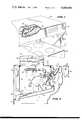
- FIG. 1is a perspective view of ventilating apparatus shown in typical operative association with a kitchen cooking appliance, where the improved damper actuating means is incorporated in the apparatus;
- FIG. 2is a sectional view of the hood showing the specific exhaust flow path from the kitchen through a grease extractor section to the exhaust duct, and the damper and actuating means therefor;
- FIG. 3is a water flow schematic for the water wash and damper actuation control used in the subject apparatus
- FIG. 4is an electrical schematic for the water wash and damper actuator control used in the subject apparatus.
- FIG. 1shows a kitchen cooking appliance in the form of a range 10, and a hood 12 is vertically spaced above and in general overlying relationship thereto.
- the hood 12has opposed side walls 14 (only one being shown) and a rear wall 16 upstanding from general proximity of the cooking appliance and terminating at a top wall 18.
- a front wall 20downwardly depends from top wall 18 and interconnects the opposed side walls 14 to form an inverted cuplike structure, as is well known.
- An exhaust duct 22communicates upwardly from an opening in the top wall 18 of the hood and is adapted to pass through the building structure, such as the walls or the roof, to discharge ultimately into the outside atmosphere.
- a fan unit or blower 24is generally mounted in the exhaust duct passage, frequently at a discharge plenum located on the roof or in a wall opening, but the same is illustrated in the duct itself in a semi-schematic manner.
- a motor 26powers the fan 24 which creates a negative pressure in the duct to induce forced ventilation of kitchen air and fumes through the vent inlet 28 and out the exhaust duct 22.
- vent structureThere further is typically associated with the vent structure a means for removing grease from the air to minimize the grease build-up in the exhaust duct 22 and further frequently to satisfy local building codes.
- the type illustrated hereinis commonly known as a centrifugal grease extractor where the air has a relatively uninterrupted but tortuous path between the vent inlet 28 and the exhaust duct.
- the illustrated grease extractorhas a front wall 30 above the inlet 28 previously noted, an inclined bottom portion located below the inlet and comprises of an outer wall 32 and inner walls 34 and 35, a vertical rear wall 36, and top baffle wall having a forward portion 38 that extends rearwardly from front wall 30 in general parallel relationship to the inner wall portion 34 and an inclined rear portion 40 that ends at a trough 41 spaced above the inner wall portion 34 forwardly of the rear wall 36.
- an intermediate baffle 42upstands from the inner wall portion 34, and a damper 44 pivoted at pin 46, when opened, presents a lower edge 47 spaced forwardly of the intermediate baffle 42 and above the inner wall portion 34.
- the air drawn into the inlet 28is forced to curve, as generally shown by line 48, down around the lower edge 47 of the damper and then up over baffle 42 and then down around the inclined rear portion to of the top baffle and up again along rear wall 36.
- line 48The air drawn into the inlet 28 is forced to curve, as generally shown by line 48, down around the lower edge 47 of the damper and then up over baffle 42 and then down around the inclined rear portion to of the top baffle and up again along rear wall 36.
- a drain pipe 49 connected to the lowest area of these wallsis used to carry away the collected grease to a point of discharge remote from the extractor unit.
- the wash system shownhas an inlet water pipe 50 extended into extractor plenum area 51 above the top baffle wall portions 38 and 40 and adjacent one of the side walls 14, and downwardly through an opening in the forward portion 38 and then crosswise of the inlet air flow.
- a plurality of nozzles 52are located along the pipe suited for discharging high pressure water, with or without detergent, into the plenum for high velocity discharge against the walls thereof to remove the grease and dirt built up on the walls and flush the same down the drain pipe 49.
- the particular location of the grease extraction meansis more completely covered in U.S. Pat. No. 4,022,118, but it is generally envisioned that any wash system having sufficient coverage and pressure to generally blanket the interior walls of the extractor plenum and baffles would suffice.
- the work systemfurther serves as a means for minimizing the chances of a fire spread through the duct system and thereby satisfies many safety code requirements for such equipment.
- damper 44which is pivoted about pin 46, and the damper can be shifted between two operative positions, namely the open position illustrated in FIG. 2 allowing the passage of air through the inlet, and the closed position where the damper lies across and closes the inlet to preclude the passage of air through the vent.
- the particular mounting means and construction of the damper 44is more thoroughly covered in my copending application entitled “Kitchen Ventilator Damper Construction” which was filed Dec. 8, 1975, having Ser. no. 638,502 now U.S. Pat. No. 4.029,002.
- the particular mechanical means 58 for moving the damper 44 between the open and closed positionsis illustrated in FIGS. 1 and 2, and includes a fluid power actuator in the form of a power cylinder 60.
- the power cylinderhas an interior piston 62 (illustrated in schematic in FIG. 3) connected by rod 64 to a yoke 66, which in turn is pivoted to a bracket secured to the front face of the damper 44.
- the power cylinderitself is connected to a bracket 68 which in turn is mounted on the front wall 30 of the extractor section.
- FIG. 3shows a preferred manner of connection of the fluid actuator for control and operation of the same.
- a hot water inlet line 70connects through a valve 72, a strainer 74, and a pressure switch 75, to a tee 76, where one leg of the tee connects through a one-way check valve 78 to a tee leading off in line 79 to a pressure reservoir 80 and in the line 81 as inlet line to a four-way valve 82.
- Two lines 83 and 85extend also from the output side of the valve and connect to the opposite end chambers 83a and 85a of the power cylinder 60.
- the valveis normally biased by spring 86 to the closed position (as shown in schematic representation in FIG.
- the valve 82thus has two operative positions that respectively interconnect two pairs of ports, each pair consisting of an infeed port and an outfeed port. Concerning the first pair of infeed and outfeed ports, the infeed port is connected by line 81 to the source of fluid and the outfeed port is connected by line 87 to the drain.
- the second pair of infeed and outfeed portsis connected by lines 83 and 85 to the opposite end chambers of the power cylinder 60. It should be noted that the direction of fluid flow through the second mentioned pair of infeed and outfeed ports is reversed as the valve is shifted between its opposite operative positions, so that the respective ports of the second mentioned pair of ports alternately act as infeed and outfeed ports.
- the pressure reservoir 80is an inverted tank having a small inlet line 79. Water pressure generated in the line 79 causes some water to flow into the tank until the pressure is balanced by the compression of the air trapped at the top of the tank, at which time the air remains confined at the top of the tank and water is at the lower section of the tank. With the check valve 78, should there be a drop in pressure of the inlet supply of the water at line 70, the reserve pressure and water remain in the pressure reservoir 80. The reserve pressure and volume of the water in the tank is sufficient, should there be a need for it and upon the shifting of the four-way valve 82, to force water through the appropriate connections to actuate the power cylinder 60 and shift the damper. Thus, even in the event of a water pressure failure, such as someone closing and inadvertantly leaving closed a water valve, the system would yet operate to close the damper should a fire occur in the building.
- the hot water line 91 from the tee 76connects through a wash valve 92 controlled by wash solenoid 93, an anti-siphon vacuum breaker 95 in the system, and through a tee 96 to the hot water spray pipe 50 for discharging as previously noted from the discharge nozzles 52.
- a tank 97 of detergentfurther is provided which connects through a pump 98 and a one-way check valve 99 to the tee 96 for admission of detergent into the hot water spray system for thorough removal of any dirt or grease from the plenum walls.
- FIG. 3provides for both opening and closing the damper with a positive mechanical force of the cylinder 60 even though it is accomplished solely by the provision of water pressure of the type readily available in a commercial building.
- the illustrated valve 82is electrically actuated to one position and spring returned to the other position, and the connection is made so that should there be a loss of electrical power, the damper would nonetheless remain in or be shifted to the closed position, since the spring biased valve would connect the high pressure water line 81 to the end chamber 85a of the power cylinder means 60.
- FIG. 4illustrates a control which is preferred for versatile use of the invention as thus far disclosed.
- L1connects through a main on-off switch 101 to common hot terminal 102.
- the blower or fan motor 26is operated for powered ventilation, as well as the damper solenoid is energized to provide that the damper is open.
- the power at hot terminal 102is normally connected via line 103 across normally closed contacts 104 of a fire relay 105, across the closed contacts 106 of water pressure switch 75, and across normally closed contacts of a stop switch 108 to terminal 109.
- the closed contactscomplete a circuit from the hot terminal 109 through coil 111 of a damper and blower relay 112 to energize the relay and further close the normally open contacts 113 and 115 of the relay.
- the coil 111remains energized by the circuit from the hot terminal 102 across the normally closed contacts 117 of wash relay 118 to terminal 119 and across the now closed relay contacts 113.
- blower motor 26With blower and damper relay 112 energized, the blower motor 26 likewise is energized by the circuit across closed contacts 113 from the hot terminal 119, as well as is a green indicator light 120 connected in parallel circuit with the blower to indicate by visual means that the blower is energized. Power is also connected from hot terminal 119 across the now closed contacts 115 to the damper solenoid 84 to shift the four-way valve 82 to open the damper as previously noted.
- the ventilation devicewould normally operate in this fashion, with the damper open and the blower or fan operating, to extract fumes from the kitchen in the customary manner.
- the operatorneed only momentarily shift the stop switch 108, at which time power from the hot terminal 102 is connected across the other contacts of the stop switch through terminal 122 to coil 123 of the wash relay 118 to energize the relay.
- the wash relayupon being energized opens the normally closed contacts 117 to interrupt power to terminal 119 to deenergize the blower and damper relay 112, which stops the blower and allows shifting of the four-way valve 82 to close the damper; and further closed normally open contacts 124 of the relay.
- the closed wash relay contacts 124deliver power from hot terminal 102 to maintain coil 123 energized, and also delivers power to wash solenoid 93 and across normally closed contacts 126 of a test switch to motor 127 for operating detergent pump 98 to effect a wash cycle.
- the wash relay 118 as hereinpreferably designed remains energized for a timed duration of 3 to 6 minutes, for example, during which time water and detergent discharged from the spray nozzles as above noted completes a wash cycle. However, it is desirable to provide a slight delay of approximately 5-10 seconds before opening the wash valve 92, in order to allow the blower to physically stop and the damper to physically close.
- wash duration timer 130 and wash delay timer 132are in the circuit between terminal 122 and the ground potential.
- the wash duration timer 130is energized with the relay coil 123 and operates to maintain the coil energized for the set duration of the wash cycle, for example, for a 5-minute time span.
- the internal connection within itself between terminals 133 and 134thus would complete and hold the circuit from the relay coil 123 to the ground potential.
- the internal connection across terminals 133 and 134would break to deenergize the relay coil 123 and in turn the relay 118.
- the power at terminal 122renders the one side of the wash solenoid 93 hot, and this is conncted through the solenoid across terminals 138 and 139 of the delay timer 132 to ground.
- the delay timerallows only a trinkle flow of current across the terminals 138 and 139, enough to actuate the timer but not enough to energize the wash solenoid 93.
- a circuitis completed across the terminals 138 and 139 which is sufficient to energize the wash solenoid and maintain the same energized until the wash timer 130 times out.
- the coil 123becomes deenergized to open the timer contacts 124, and this deenergizes the wash solenoid 93 and detergent pump motor 127 and terminates the wash cycle.
- Suitable timers 130 and 132 for performing the aboveare available from SSAC Precision Products Incorporated of Liverpool, NY, under model numbers TS 2424 and TS 1422, respectively.
- the detergent pumpcan be tested at any time for checking its proper functioning or for the presence of detergent in the system by shifting the test switch against the opposite contact which completes a circuit from the terminal 109, which normally is hot when the switch 101 is closed.
- a wash cycleis automatically started and operated for a set duration every time that the operator shifts the stop switch 108 from its normal position as shown.
- damper 44should be closed to provide visual assurance to the operator that the damper controls are properly working.
- the timer contacts 117once again close and allow for the terminal 119 to be hot and this thereby readies the apparatus for a normal operating cycle where the blower would be working and the damper would be open; and this cycle is started by momentarily closing the contacts of start switch 110.
- the disclosed controlautomatically leaves the damper in its closed position to preclude the transfer of air into or from the building through the vent inlet 28. This provides for certain savings of heating energy, particularly during the cooler months by stopping the chimmey effect that otherwise occurs where the kitchen ventilating system is normally maintained opened even when it is not in use.
- another main purpose of this particular inventionis to provide for improved operational characteristics in the event of a fire. Under such circumstances, the detection of a fire should automatically close the damper, stop the exhaust fan or blower, and discharge fire quenching water into the duct system.
- thermostat 142there are two ways to instigate a fire cycle; one being manual actuation of a fire switch 140 and the other being automatically upon sensing of excess heat by a thermostat 142.
- the switch 140 and thermostat 142are in a parallel circuit between hot terminal 102 and relay coil 146 of the fire relay 105. Normally, the thermostat would have contacts that are open and closed only in the event of sensing a heat which is indicative of the presence of a fire.
- the thermostatmight be located physically in the exhaust duct 22 as is evidenced by the projecting terminal 143.
- the normally open contacts 148 and 150are closed, and contacts 104 are opened.
- the closed contacts 150complete through normally closed contacts 152 of a manual reset switch a holding circuit from hot terminal 102 and through terminal 144 with the coil 146 to maintain the relay energized until the manual reset switch is depressed and the contact 152 are opened.
- the closed contacts 148completes a circuit from the hot terminal 102 to the wash relay coil 123 which instigates a wash cycle, as previously noted. This terminates power to the terminal 119 upon opening the normally closed contacts 117, to close the damper and stop the blower, and further causes the discharge of water under pressure from the nozzles 52 into the interior of the grease extractor and plenum.
- a major advantage of the disclosed inventionis the fact that the damper is automatically closed by means completely independent of mechanical or electrical energy, and relies solely on water pressure within a water system in the building itself or within the pressure reservoir 80 previously noted. Moreover, the damper mechanism and control operates on a regular basis every time the ventilator blower is started and stopped, so that there is little chance for an operator to be deceived into believing the fire detection mechanism is operable where in fact it is not, since the same is visually checked every day.
- the water pressure switch contacts 106will open upon an insufficient pressure at the sensed location of the device 75 in the line, and further will shift against terminal 156 to illuminate a red indicator light 158. Under such low water pressure sensed conditions, terminal 109 is neutral and a new operating cycle cannot be started to start the blower or open the damper; however, an operating cycle will continue as long as terminal 119 remains hot.
Landscapes
- Engineering & Computer Science (AREA)
- Mechanical Engineering (AREA)
- Health & Medical Sciences (AREA)
- Public Health (AREA)
- Business, Economics & Management (AREA)
- Emergency Management (AREA)
- Chemical & Material Sciences (AREA)
- Combustion & Propulsion (AREA)
- General Engineering & Computer Science (AREA)
- Ventilation (AREA)
Abstract
Description
Claims (14)
Priority Applications (2)
| Application Number | Priority Date | Filing Date | Title |
|---|---|---|---|
| US05/674,816US4066064A (en) | 1976-04-08 | 1976-04-08 | Kitchen ventilator damper actuator and control |
| CA275,757ACA1110101A (en) | 1976-04-08 | 1977-04-06 | Kitchen ventilator damper actuator and control |
Applications Claiming Priority (1)
| Application Number | Priority Date | Filing Date | Title |
|---|---|---|---|
| US05/674,816US4066064A (en) | 1976-04-08 | 1976-04-08 | Kitchen ventilator damper actuator and control |
Publications (1)
| Publication Number | Publication Date |
|---|---|
| US4066064Atrue US4066064A (en) | 1978-01-03 |
Family
ID=24707995
Family Applications (1)
| Application Number | Title | Priority Date | Filing Date |
|---|---|---|---|
| US05/674,816Expired - LifetimeUS4066064A (en) | 1976-04-08 | 1976-04-08 | Kitchen ventilator damper actuator and control |
Country Status (2)
| Country | Link |
|---|---|
| US (1) | US4066064A (en) |
| CA (1) | CA1110101A (en) |
Cited By (35)
| Publication number | Priority date | Publication date | Assignee | Title |
|---|---|---|---|---|
| US4271683A (en)* | 1979-07-26 | 1981-06-09 | Hester Industries, Inc. | High humidity food chilling system |
| US4363642A (en)* | 1977-03-25 | 1982-12-14 | Hardee's Food Systems, Inc. | Control of range hood emissions |
| WO1985000873A1 (en)* | 1983-08-11 | 1985-02-28 | Muckler, Richard, F. | Kitchen ventilating system |
| US4753218A (en)* | 1987-02-09 | 1988-06-28 | Cambridge Engineering, Inc. | Continuous water wash hood type ventilating system |
| US4784114A (en)* | 1982-05-05 | 1988-11-15 | Richard F. Muckler | Kitchen ventilating system |
| USRE33510E (en)* | 1979-07-26 | 1991-01-01 | Hester Industries, Inc. | High humidity steam cooker with continuously running conveyor |
| US5235963A (en)* | 1992-08-10 | 1993-08-17 | Strause James F | Exhaust duct cleaning system |
| US5292353A (en)* | 1991-07-03 | 1994-03-08 | The Delfield Company | Air scrubber |
| EP0612962A1 (en)* | 1993-02-23 | 1994-08-31 | MAIMER GmbH | Fume extracting hood, in particular for large-scale kitchens |
| US5642784A (en)* | 1996-02-16 | 1997-07-01 | Sani Metal Ltd. | Exhaust hood apparatus |
| US5860412A (en)* | 1997-11-05 | 1999-01-19 | Way; Joseph E. | Kitchen ventilation duct degreasing system |
| US6125841A (en)* | 1997-04-23 | 2000-10-03 | Boudreault; Jean-Pierre | Method and apparatus for combined removal and in-situ biodegradation of grease material from a kitchen ventilator |
| US6511844B1 (en) | 2000-02-11 | 2003-01-28 | Michael A. Smith | Air purification system and method of using the same |
| US6584968B1 (en)* | 2000-09-25 | 2003-07-01 | Itw Food Equipment Group Llc | Kitchen ventilator and associated control method |
| US6797246B2 (en)* | 1999-09-20 | 2004-09-28 | Danny L. Hopkins | Apparatus and method for cleaning, neutralizing and recirculating exhaust air in a confined environment |
| FR2865419A1 (en)* | 2004-01-22 | 2005-07-29 | Gabriel Sylvestre | Hood and ceiling filters cleaning and degreasing process for use in e.g. public kitchen, involves directing spray nozzles/injectors in hood and ceiling, towards backside of filters to spray water mixed with biological products |
| US7104263B1 (en)* | 2005-04-27 | 2006-09-12 | Po-Chang Chen | Detergent supply system for a self-cleaning kitchen hood |
| US20070119448A1 (en)* | 2002-04-12 | 2007-05-31 | Peter Yeung | Range hood cleaning assembly |
| US20070209655A1 (en)* | 2006-03-10 | 2007-09-13 | Kellogg David A | Range exhaust cleaning system and method |
| US20070221199A1 (en)* | 2006-03-24 | 2007-09-27 | Duke Manufacturing Co. | Vent system for cooking appliance |
| US20080045132A1 (en)* | 2004-06-22 | 2008-02-21 | Oy Halton Group Ltd. | Set And Forget Exhaust Controller |
| US20080066627A1 (en)* | 2003-09-16 | 2008-03-20 | Salvatore Lamartino | Cooling air system for a patty-forming apparatus |
| US20080308088A1 (en)* | 2005-01-06 | 2008-12-18 | Oy Halton Group Ltd. | Low Profile Exhaust Hood |
| US20090093210A1 (en)* | 2007-10-09 | 2009-04-09 | Oy Halton Group Ltd. | Damper suitable for liquid aerosol-laden flow streams |
| US20090272372A1 (en)* | 2008-05-02 | 2009-11-05 | Captive-Aire Systems, Inc. | Kitchen Hood Assembly with a Combination Cleaning and Fire Suppression System |
| US20120079946A1 (en)* | 2010-10-04 | 2012-04-05 | Jeffrey Bennett Dold | Self-cleaning vapor-condensing grease baffle filter |
| US8746231B2 (en) | 2006-03-10 | 2014-06-10 | Kbs Automist, Llc | Range exhaust cleaning system and method |
| CN104747464A (en)* | 2015-02-27 | 2015-07-01 | 北海和思科技有限公司 | Noise reduction and fume discharge device specially used in catering industry |
| US9134036B2 (en) | 2010-01-13 | 2015-09-15 | Oy Halton Group Ltd. | Oven exhaust hood methods, devices, and systems |
| US20170052545A1 (en)* | 2015-08-19 | 2017-02-23 | Robert Cortez | Gas monitoring and energy recycling system |
| CN108317325A (en)* | 2017-01-15 | 2018-07-24 | 程长青 | The input and output material three-way connection in roller drying storehouse |
| US10137384B2 (en)* | 2009-12-11 | 2018-11-27 | Micronic Technologies, Inc. | Systems and methods for water desalinization |
| US20190271384A1 (en)* | 2018-03-01 | 2019-09-05 | GM Global Technology Operations LLC | Transmission pressure controlled vent system |
| US20200147425A1 (en)* | 2018-11-14 | 2020-05-14 | The Boeing Company | Ventilation closure system |
| WO2023056154A1 (en)* | 2021-10-01 | 2023-04-06 | Oy Halton Group Ltd. | Fire detection and warning systems, devices, and methods for kitchen ventilation |
Citations (8)
| Publication number | Priority date | Publication date | Assignee | Title |
|---|---|---|---|---|
| US2311374A (en)* | 1938-11-01 | 1943-02-16 | American District Telegraph Co | Automatic fire control system for ventilating or air conditioning systems |
| US2648346A (en)* | 1952-05-19 | 1953-08-11 | Bendix Aviat Corp | Locking valve for hydraulic motors |
| US3055285A (en)* | 1959-11-03 | 1962-09-25 | Gaylord Ind | Kitchen ventilating system |
| US3207058A (en)* | 1962-09-21 | 1965-09-21 | Asa K Gaylord | Kitchen ventilating system |
| US3785124A (en)* | 1971-08-02 | 1974-01-15 | Gaylord Ind | Pollution-free kitchen ventilator |
| US3802493A (en)* | 1971-12-13 | 1974-04-09 | A Goettl | Air conditioning apparatus |
| US3805685A (en)* | 1973-01-15 | 1974-04-23 | Fischer Ind Inc | Method and apparatus for cleaning grease filters in a ventilating system |
| US3831643A (en)* | 1973-05-21 | 1974-08-27 | Black Prod Co | Bag filling machine having door-type inlet valve |
- 1976
- 1976-04-08USUS05/674,816patent/US4066064A/ennot_activeExpired - Lifetime
- 1977
- 1977-04-06CACA275,757Apatent/CA1110101A/ennot_activeExpired
Patent Citations (8)
| Publication number | Priority date | Publication date | Assignee | Title |
|---|---|---|---|---|
| US2311374A (en)* | 1938-11-01 | 1943-02-16 | American District Telegraph Co | Automatic fire control system for ventilating or air conditioning systems |
| US2648346A (en)* | 1952-05-19 | 1953-08-11 | Bendix Aviat Corp | Locking valve for hydraulic motors |
| US3055285A (en)* | 1959-11-03 | 1962-09-25 | Gaylord Ind | Kitchen ventilating system |
| US3207058A (en)* | 1962-09-21 | 1965-09-21 | Asa K Gaylord | Kitchen ventilating system |
| US3785124A (en)* | 1971-08-02 | 1974-01-15 | Gaylord Ind | Pollution-free kitchen ventilator |
| US3802493A (en)* | 1971-12-13 | 1974-04-09 | A Goettl | Air conditioning apparatus |
| US3805685A (en)* | 1973-01-15 | 1974-04-23 | Fischer Ind Inc | Method and apparatus for cleaning grease filters in a ventilating system |
| US3831643A (en)* | 1973-05-21 | 1974-08-27 | Black Prod Co | Bag filling machine having door-type inlet valve |
Cited By (52)
| Publication number | Priority date | Publication date | Assignee | Title |
|---|---|---|---|---|
| US4363642A (en)* | 1977-03-25 | 1982-12-14 | Hardee's Food Systems, Inc. | Control of range hood emissions |
| US4271683A (en)* | 1979-07-26 | 1981-06-09 | Hester Industries, Inc. | High humidity food chilling system |
| USRE33510E (en)* | 1979-07-26 | 1991-01-01 | Hester Industries, Inc. | High humidity steam cooker with continuously running conveyor |
| USRE35259E (en)* | 1979-07-26 | 1996-06-04 | Hester Industries, Inc. | High humidity steam cooker with continuously running conveyor |
| US4784114A (en)* | 1982-05-05 | 1988-11-15 | Richard F. Muckler | Kitchen ventilating system |
| WO1985000873A1 (en)* | 1983-08-11 | 1985-02-28 | Muckler, Richard, F. | Kitchen ventilating system |
| US4753218A (en)* | 1987-02-09 | 1988-06-28 | Cambridge Engineering, Inc. | Continuous water wash hood type ventilating system |
| US5292353A (en)* | 1991-07-03 | 1994-03-08 | The Delfield Company | Air scrubber |
| US5235963A (en)* | 1992-08-10 | 1993-08-17 | Strause James F | Exhaust duct cleaning system |
| EP0612962A1 (en)* | 1993-02-23 | 1994-08-31 | MAIMER GmbH | Fume extracting hood, in particular for large-scale kitchens |
| US5642784A (en)* | 1996-02-16 | 1997-07-01 | Sani Metal Ltd. | Exhaust hood apparatus |
| US6125841A (en)* | 1997-04-23 | 2000-10-03 | Boudreault; Jean-Pierre | Method and apparatus for combined removal and in-situ biodegradation of grease material from a kitchen ventilator |
| US5860412A (en)* | 1997-11-05 | 1999-01-19 | Way; Joseph E. | Kitchen ventilation duct degreasing system |
| US6797246B2 (en)* | 1999-09-20 | 2004-09-28 | Danny L. Hopkins | Apparatus and method for cleaning, neutralizing and recirculating exhaust air in a confined environment |
| US6511844B1 (en) | 2000-02-11 | 2003-01-28 | Michael A. Smith | Air purification system and method of using the same |
| US6584968B1 (en)* | 2000-09-25 | 2003-07-01 | Itw Food Equipment Group Llc | Kitchen ventilator and associated control method |
| US20070119448A1 (en)* | 2002-04-12 | 2007-05-31 | Peter Yeung | Range hood cleaning assembly |
| US20080066627A1 (en)* | 2003-09-16 | 2008-03-20 | Salvatore Lamartino | Cooling air system for a patty-forming apparatus |
| FR2865419A1 (en)* | 2004-01-22 | 2005-07-29 | Gabriel Sylvestre | Hood and ceiling filters cleaning and degreasing process for use in e.g. public kitchen, involves directing spray nozzles/injectors in hood and ceiling, towards backside of filters to spray water mixed with biological products |
| US7775865B2 (en) | 2004-06-22 | 2010-08-17 | Oy Halton Group Ltd. | Set and forget exhaust controller |
| US20080045132A1 (en)* | 2004-06-22 | 2008-02-21 | Oy Halton Group Ltd. | Set And Forget Exhaust Controller |
| US9664395B2 (en) | 2005-01-06 | 2017-05-30 | Oy Halton Group, Ltd. | Low profile exhaust hood |
| US9239169B2 (en) | 2005-01-06 | 2016-01-19 | Oy Halton Group Ltd. | Low profile exhaust hood |
| US20080308088A1 (en)* | 2005-01-06 | 2008-12-18 | Oy Halton Group Ltd. | Low Profile Exhaust Hood |
| US7104263B1 (en)* | 2005-04-27 | 2006-09-12 | Po-Chang Chen | Detergent supply system for a self-cleaning kitchen hood |
| US7832391B2 (en)* | 2006-03-10 | 2010-11-16 | Kellogg, Bruns & Smeija, LLC | Range exhaust cleaning system |
| US20070209655A1 (en)* | 2006-03-10 | 2007-09-13 | Kellogg David A | Range exhaust cleaning system and method |
| US8746231B2 (en) | 2006-03-10 | 2014-06-10 | Kbs Automist, Llc | Range exhaust cleaning system and method |
| US20110048397A1 (en)* | 2006-03-10 | 2011-03-03 | Kellogg, Bruns & Smeija, LLC | Range exhaust cleaning system and method |
| US8316839B2 (en) | 2006-03-10 | 2012-11-27 | Kbs Automist, Llc | Range exhaust cleaning system and method |
| US20070221199A1 (en)* | 2006-03-24 | 2007-09-27 | Duke Manufacturing Co. | Vent system for cooking appliance |
| US9719686B2 (en) | 2007-10-09 | 2017-08-01 | Oy Halton Group Ltd. | Damper suitable for liquid aerosol-laden flow streams |
| US10480797B2 (en) | 2007-10-09 | 2019-11-19 | Oy Halton Group Ltd. | Damper suitable for liquid aerosol-laden flow streams |
| US20090093210A1 (en)* | 2007-10-09 | 2009-04-09 | Oy Halton Group Ltd. | Damper suitable for liquid aerosol-laden flow streams |
| US9702565B2 (en) | 2007-10-09 | 2017-07-11 | Oy Halto Group Ltd. | Damper suitable for liquid aerosol-laden flow streams |
| US7963282B2 (en)* | 2008-05-02 | 2011-06-21 | Captive-Aire Systems, Inc. | Kitchen hood assembly with a combination cleaning and fire suppression system |
| US20090272372A1 (en)* | 2008-05-02 | 2009-11-05 | Captive-Aire Systems, Inc. | Kitchen Hood Assembly with a Combination Cleaning and Fire Suppression System |
| US10137384B2 (en)* | 2009-12-11 | 2018-11-27 | Micronic Technologies, Inc. | Systems and methods for water desalinization |
| EP3081865A2 (en) | 2010-01-13 | 2016-10-19 | OY Halton Group, Ltd. | Oven exhaust hood methods and device |
| US9134036B2 (en) | 2010-01-13 | 2015-09-15 | Oy Halton Group Ltd. | Oven exhaust hood methods, devices, and systems |
| US9777929B2 (en) | 2010-01-13 | 2017-10-03 | Oy Halton Group Ltd. | Oven exhaust hood methods, devices, and systems |
| US10215421B2 (en) | 2010-01-13 | 2019-02-26 | Oy Halton Group Ltd. | Oven exhaust hood methods, devices, and systems |
| US11137146B2 (en) | 2010-01-13 | 2021-10-05 | Oy Halton Group Ltd. | Oven exhaust hood methods, devices, and systems |
| US20120079946A1 (en)* | 2010-10-04 | 2012-04-05 | Jeffrey Bennett Dold | Self-cleaning vapor-condensing grease baffle filter |
| CN104747464A (en)* | 2015-02-27 | 2015-07-01 | 北海和思科技有限公司 | Noise reduction and fume discharge device specially used in catering industry |
| US20170052545A1 (en)* | 2015-08-19 | 2017-02-23 | Robert Cortez | Gas monitoring and energy recycling system |
| CN108317325A (en)* | 2017-01-15 | 2018-07-24 | 程长青 | The input and output material three-way connection in roller drying storehouse |
| US10948068B2 (en)* | 2018-03-01 | 2021-03-16 | GM Global Technology Operations LLC | Transmission pressure controlled vent system |
| US20190271384A1 (en)* | 2018-03-01 | 2019-09-05 | GM Global Technology Operations LLC | Transmission pressure controlled vent system |
| US20200147425A1 (en)* | 2018-11-14 | 2020-05-14 | The Boeing Company | Ventilation closure system |
| US10898743B2 (en)* | 2018-11-14 | 2021-01-26 | The Boeing Company | Ventilation closure system |
| WO2023056154A1 (en)* | 2021-10-01 | 2023-04-06 | Oy Halton Group Ltd. | Fire detection and warning systems, devices, and methods for kitchen ventilation |
Also Published As
| Publication number | Publication date |
|---|---|
| CA1110101A (en) | 1981-10-06 |
Similar Documents
| Publication | Publication Date | Title |
|---|---|---|
| US4066064A (en) | Kitchen ventilator damper actuator and control | |
| AU548848B2 (en) | Water spray fire protection for hoods over cooking units | |
| US4784114A (en) | Kitchen ventilating system | |
| US3653443A (en) | Fire extinguishing system for cook stoves and ranges | |
| US2813477A (en) | Safety ventilator unit | |
| US3785124A (en) | Pollution-free kitchen ventilator | |
| US3207058A (en) | Kitchen ventilating system | |
| US4830116A (en) | Fire extinguishing system | |
| US3690245A (en) | Range hood unit with fire safeguard fan control system | |
| US3433146A (en) | Grease extracting ventilating apparatus | |
| US6648077B2 (en) | Fire extinguishing system | |
| US4085735A (en) | Air ventilation and washing system | |
| US4773485A (en) | Fire extinguishing system for cookstove and ranges | |
| US3055285A (en) | Kitchen ventilating system | |
| US3786739A (en) | Ventilating system | |
| US3905385A (en) | Steam trap | |
| US3564989A (en) | Fire prevention system | |
| US3033191A (en) | Broiling apparatus | |
| WO2008065332A2 (en) | A kitchen ventilation system | |
| US4103676A (en) | Grease extraction cartridge for kitchen exhaust ventilator | |
| US4223599A (en) | Spray booth with energy saving and fire protection systems | |
| EP0151567A1 (en) | Kitchen ventilating system | |
| JPH0439550A (en) | Heating and cooking device | |
| CA1273524A (en) | Ventilation control system | |
| US2166834A (en) | Draft control for furnaces |
Legal Events
| Date | Code | Title | Description |
|---|---|---|---|
| STCF | Information on status: patent grant | Free format text:PATENTED FILE - (OLD CASE ADDED FOR FILE TRACKING PURPOSES) | |
| AS | Assignment | Owner name:BASTIAN ADVANCED SYSTEM, INC. Free format text:CHANGE OF NAME;ASSIGNOR:INTERNATIONAL FOOD SERVICE EQUIPMENT SYSTEMS, INC.;REEL/FRAME:004245/0581 | |
| AS | Assignment | Owner name:BIH FOODSERVICE, INC., FORMERLY KNOWN AS INTERNATI Free format text:RELEASED BY SECURED PARTY;ASSIGNOR:CONGRESS FINANCIAL CORPORATION;REEL/FRAME:004392/0760 Effective date:19850123 Owner name:GENERAL ELECTRIC CREDIT CORPORATION, CONNECTICUT Free format text:SECURITY INTEREST;ASSIGNOR:BIH FOODSERVICE,INC.;REEL/FRAME:004387/0714 Effective date:19850123 | |
| AS | Assignment | Owner name:GENERAL ELECTRIC CREDIT CORPORATION, CONNECTICUT Free format text:SECURITY INTEREST;ASSIGNOR:BIH FOODSERVICE, INC.;REEL/FRAME:004404/0344 Effective date:19850123 | |
| AS | Assignment | Owner name:HUSSMANN CORPORATION, 12999 ST. CHARLES ROCK ROAD, Free format text:ASSIGNMENT OF ASSIGNORS INTEREST.;ASSIGNOR:GENERAL ELECTRIC CREDIT CORPORATION;REEL/FRAME:004489/0491 Effective date:19851031 | |
| AS | Assignment | Owner name:MIDDLEBY MARSHALL, INC., A CORP. OF DE, ILLINOIS Free format text:ASSIGNMENT OF ASSIGNORS INTEREST.;ASSIGNOR:HUSSMANN CORPORATION;REEL/FRAME:005127/0235 Effective date:19890714 | |
| AS | Assignment | Owner name:CITIBANK, N.A., A NATIONAL BANKING ASSOCIATION, AS Free format text:SECURITY INTEREST;ASSIGNOR:MIDDLEBY MARSHALL INC.;REEL/FRAME:005159/0878 Effective date:19890714 | |
| AS | Assignment | Owner name:BOATMEN'S NATIONAL BANK OF ST. LOUIS, THE, MISSOUR Free format text:SECURITY INTEREST;ASSIGNOR:SOUTHERN ACQUISITION COMPANY OF ST. LOUIS, (IN THE FUTURE TO BE KNOWN AS SOUTHERN EQUIPMENT COMPANY), 4550 GUSTINE, ST. LOUIS, MO. 63116, A CORP. OF DE.;REEL/FRAME:005253/0350 Effective date:19900209 Owner name:MIDDLEBY MARSHALL INC., A CORP. OF DE. Free format text:RELEASED BY SECURED PARTY;ASSIGNOR:CITIBANK, N.A., AS AGENT;REEL/FRAME:005253/0360 Effective date:19900209 Owner name:SOUTHERN ACQUISITION COMPANY OF ST. LOUIS, MISSOUR Free format text:ASSIGNMENT OF ASSIGNORS INTEREST.;ASSIGNOR:MIDDLEBY MARSHALL INC., 8300 AUSTIN AVE., MORTON GROVE, IL. 60053, A CORP. OF DE.;REEL/FRAME:005253/0357 Effective date:19900209 | |
| AS | Assignment | Owner name:MIDDLEBY MARSHALL INC., TEXAS Free format text:RELEASE BY SECURED PARTY;ASSIGNOR:CITIBANK, N.A.;REEL/FRAME:007417/0486 Effective date:19950110 |