US4061698A - Humidifier-nebulizer apparatus - Google Patents
Humidifier-nebulizer apparatusDownload PDFInfo
- Publication number
- US4061698A US4061698AUS05/569,229US56922975AUS4061698AUS 4061698 AUS4061698 AUS 4061698AUS 56922975 AUS56922975 AUS 56922975AUS 4061698 AUS4061698 AUS 4061698A
- Authority
- US
- United States
- Prior art keywords
- passage
- nebulizer
- liquid
- discharge
- humidifier
- Prior art date
- Legal status (The legal status is an assumption and is not a legal conclusion. Google has not performed a legal analysis and makes no representation as to the accuracy of the status listed.)
- Expired - Lifetime
Links
- 239000006199nebulizerSubstances0.000titleclaimsabstractdescription39
- 239000007788liquidSubstances0.000claimsabstractdescription69
- 230000000694effectsEffects0.000claimsabstractdescription9
- 239000000203mixtureSubstances0.000claimsabstractdescription9
- 239000000945fillerSubstances0.000claimsdescription26
- 238000004891communicationMethods0.000claimsdescription16
- 230000002093peripheral effectEffects0.000claimsdescription5
- 239000007789gasSubstances0.000abstractdescription42
- QVGXLLKOCUKJST-UHFFFAOYSA-Natomic oxygenChemical compound[O]QVGXLLKOCUKJST-UHFFFAOYSA-N0.000abstractdescription10
- 239000001301oxygenSubstances0.000abstractdescription10
- 229910052760oxygenInorganic materials0.000abstractdescription10
- XLYOFNOQVPJJNP-UHFFFAOYSA-NwaterSubstancesOXLYOFNOQVPJJNP-UHFFFAOYSA-N0.000abstractdescription3
- 239000002245particleSubstances0.000description6
- 238000007789sealingMethods0.000description5
- 238000000071blow mouldingMethods0.000description4
- 238000002664inhalation therapyMethods0.000description4
- 210000002345respiratory systemAnatomy0.000description4
- 238000007664blowingMethods0.000description3
- 238000000034methodMethods0.000description3
- 230000000717retained effectEffects0.000description3
- 230000009471actionEffects0.000description2
- 230000015556catabolic processEffects0.000description2
- 238000010438heat treatmentMethods0.000description2
- 239000003595mistSubstances0.000description2
- 208000023504respiratory system diseaseDiseases0.000description2
- 210000003813thumbAnatomy0.000description2
- 206010014561EmphysemaDiseases0.000description1
- 208000006673asthmaDiseases0.000description1
- 230000004323axial lengthEffects0.000description1
- 238000009833condensationMethods0.000description1
- 230000005494condensationEffects0.000description1
- 238000010276constructionMethods0.000description1
- 208000037265diseases, disorders, signs and symptomsDiseases0.000description1
- 239000012530fluidSubstances0.000description1
- 238000004519manufacturing processMethods0.000description1
- 239000000463materialSubstances0.000description1
- 239000012528membraneSubstances0.000description1
- 238000012986modificationMethods0.000description1
- 230000004048modificationEffects0.000description1
- 238000002663nebulizationMethods0.000description1
- 230000008520organizationEffects0.000description1
- 229920000098polyolefinPolymers0.000description1
- 230000008569processEffects0.000description1
- 230000002035prolonged effectEffects0.000description1
- 239000007921spraySubstances0.000description1
Images

Classifications
- A—HUMAN NECESSITIES
- A61—MEDICAL OR VETERINARY SCIENCE; HYGIENE
- A61M—DEVICES FOR INTRODUCING MEDIA INTO, OR ONTO, THE BODY; DEVICES FOR TRANSDUCING BODY MEDIA OR FOR TAKING MEDIA FROM THE BODY; DEVICES FOR PRODUCING OR ENDING SLEEP OR STUPOR
- A61M16/00—Devices for influencing the respiratory system of patients by gas treatment, e.g. ventilators; Tracheal tubes
- A61M16/10—Preparation of respiratory gases or vapours
- A61M16/14—Preparation of respiratory gases or vapours by mixing different fluids, one of them being in a liquid phase
- A61M16/16—Devices to humidify the respiration air
- A—HUMAN NECESSITIES
- A61—MEDICAL OR VETERINARY SCIENCE; HYGIENE
- A61M—DEVICES FOR INTRODUCING MEDIA INTO, OR ONTO, THE BODY; DEVICES FOR TRANSDUCING BODY MEDIA OR FOR TAKING MEDIA FROM THE BODY; DEVICES FOR PRODUCING OR ENDING SLEEP OR STUPOR
- A61M16/00—Devices for influencing the respiratory system of patients by gas treatment, e.g. ventilators; Tracheal tubes
- A61M16/20—Valves specially adapted to medical respiratory devices
- A61M16/208—Non-controlled one-way valves, e.g. exhalation, check, pop-off non-rebreathing valves
- A61M16/209—Relief valves
- A—HUMAN NECESSITIES
- A61—MEDICAL OR VETERINARY SCIENCE; HYGIENE
- A61M—DEVICES FOR INTRODUCING MEDIA INTO, OR ONTO, THE BODY; DEVICES FOR TRANSDUCING BODY MEDIA OR FOR TAKING MEDIA FROM THE BODY; DEVICES FOR PRODUCING OR ENDING SLEEP OR STUPOR
- A61M16/00—Devices for influencing the respiratory system of patients by gas treatment, e.g. ventilators; Tracheal tubes
- A61M16/10—Preparation of respiratory gases or vapours
- A61M16/105—Filters
- A61M16/106—Filters in a path
- A61M16/107—Filters in a path in the inspiratory path
- Y—GENERAL TAGGING OF NEW TECHNOLOGICAL DEVELOPMENTS; GENERAL TAGGING OF CROSS-SECTIONAL TECHNOLOGIES SPANNING OVER SEVERAL SECTIONS OF THE IPC; TECHNICAL SUBJECTS COVERED BY FORMER USPC CROSS-REFERENCE ART COLLECTIONS [XRACs] AND DIGESTS
- Y10—TECHNICAL SUBJECTS COVERED BY FORMER USPC
- Y10S—TECHNICAL SUBJECTS COVERED BY FORMER USPC CROSS-REFERENCE ART COLLECTIONS [XRACs] AND DIGESTS
- Y10S261/00—Gas and liquid contact apparatus
- Y10S261/65—Vaporizers
Definitions
- the present inventionrelates generally to humidifier and nebulizer apparatus, and more particularly to a novel humidifier-nebulizer employing an adapter head which facilitates use of the apparatus as either a humidifier or nebulizer.
- nebulizerIt is known in the treatment of persons having respiratory disorders, such as emphysema or asthma, to provide inhalation therapy through the employment of humidifers or nebulizers.
- the person affected with the disorderinhales a gas-liquid mixture from the nebulizer or humidifier.
- a nebulizeris conventionally employed to introduce a medicinal solution in the form of a fine mist, spray or vapor into a person's respiratory system, with the percentage of liquid in the gas being relatively large as compared with the discharge from a humidifier.
- the nebulizereffects a breakdown of the liquid particles carried in the gas to a size insuring that the liquid particles reach their intended destination within the person's respiratory system.
- a humidifieris effective to moisten the gas discharged in a manner to introduce a moistened gas, such as oxygen, into a person's respiratory system.
- the gasis moistened so as to prevent desiccation of the respiratory tract or membranes during treatment over a prolonged period.
- the present inventionprovides a humidifier-nebulizer which takes the form of a single unit which a patient may readily and simply adjust for use as either a humidifier or nebulizer.
- One of the primary objects of the present inventionis to provide a humidifier-nebulizer employing novel adapter head means which provide for simple adjustment to operate the apparatus in either a humidifier or nebulizer mode of operation.
- Another object of the present inventionis to provide a novel adapter head for use with a liquid reservoir, which adapter head has a body member adapted for connection to a sealed liquid reservoir and a source of pressurized gas, and has selectively movable control valve means operable in a first position to discharge a nebulized gas from the adapter head, and operable in a second position to effect discharge of a humidified gas from a discharge port on the reservoir.
- Another object of the present inventionis to provide a humidifier-nebulizer apparatus employing a novel liquid reservoir which facilitates ease of manufacture and filling of the reservoir with attendant economic savings.
- Still another object of the present inventionis to provide a humidifier-nebulizer apparatus which employs a novel liquid reservoir having a sparger member disposed between a gas input tube and a primary liquid reservoir, the sparger member being adapted to provide highly efficient and quiet operation as the gas is introduced into the liquid.
- a feature of the present inventionlies in the provision of pressure relief means on the adapter head of the humidifier-nebulizer apparatus for preventing harmful affects to the adapter head during pressure buildup in the apparatus when used in a humidifier mode of operation.
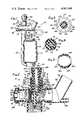
- FIG. 1is a side elevational view of a humidifier-nebulizer apparatus constructed in accordance with the present invention and shown in a nebulizing mode of operation;
- FIG. 2is an enlarged longitudinal sectional view of the adapter head assembly employed in the apparatus of FIG. 1, the adapter head being shown for use in a nebulization mode of operation;
- FIG. 3is a transverse sectional view taken substantially along the line 3--3 of FIG. 2, looking in the direction of the arrows;
- FIG. 4is a transverse sectional view taken substantially along the line 4--4 of FIG. 2, looking in the direction of the arrows;
- FIG. 5is a sectional view taken substantially along the line 5--5 of FIG. 2, looking in the direction of the arrows;
- FIG. 6is an enlarged longitudinal sectional view of the liquid reservoir used in the apparatus of FIG. 1, the liquid reservoir being in a sealed condition prior to assembly of the adapter head thereon;
- FIG. 7is a transverse sectional view taken substantially along the line 7--7 of FIG. 6 to illustrate the sparger member
- FIG. 8is an enlarged partial sectional view illustrating the discharge end of the adapter head having a sealing cap mounted thereon for use when the apparatus is used in a humidifier mode of operation;
- FIG. 9is an enlarged partial longitudinal sectional view illustrating an alternative embodiment of a control valve used in the adapter head.
- the humidifier-nebulizer apparatus 10includes liquid reservoir means, indicated generally at 12, and adapter head means, indicated generally at 14.
- the liquid reservoir 12is adapted to contain a quantity of sterile liquid such as water or a medicinal liquid, and is further adapted to have the adapter head means 14 mounted thereon.
- the adapter head means 14is connected to a source of oxygen or the like (not shown) and includes control valve means, indicated generally at 16, operative between first and second positions to allow use of the humidifier-nebulizer apparatus 10 in either a humidifying or nebulizing mode of operation.
- the humidifier-nebulizer apparatus 10is shown for use in a nebulizing mode of operation.
- the liquid reservoir means 12includes a primary or main liquid reservoir body portion 18 which terminates at its lower end in an annular wall 19.
- the reservoir body portion 18is generally rectangular in cross sectional configuration with rounded corners.
- the annular wall 19defines an opening 20 into the interior of the reservoir body 18.
- An upstanding filler tube 22is preferably formed integral with the reservoir body portion 18, as through a connecting web 24, and extends along the longitudinal length of the reservoir body portion 18.
- the upstanding filler tube 22is connected at its lower end to the annular wall 19 in communication with the opening 20, and has a sealed upper end surface 26 which extends above the top of the reservoir body 18.
- An external right-hand thread 28is formed on the outer periphery of the filler tube 22 adjacent its upper sealed end 26 to provide a threaded end upon which the adapter head means 14 may be threadedly engaged.
- the sealed end 26 of the filler tube 22is pierceable by a piercing element provided on the adapter head means 14 as will be described more fully hereinbelow.
- the upper end 28 of the reservoir body 18has an opening 30 formed therein which terminates in an upwardly extending integral cap portion 32.
- the cap portion 32has an upstanding cylindrical tubular extension 34 formed integral thereon which has an upper closed end 36 and a radially outwardly extending connector nib 38.
- the connector nib 38has annular ridges 40a, 40b and 40c formed thereon which are of progressively increasing diameter and which serve to receive and retain the end of a rubber or suitable elastomeric drain tube 42 (FIG. 1) when the humidifier-nebulizer apparatus 10 is used in a nebulizing mode of operation, and serves to receive the end of a cannula when the apparatus is used in a humidifier mode of operation.
- the liquid reservoir means 12is preferably formed of a polyolefin material which lends itself to conventional blow molding techniques.
- the liquid reservoir means 12, as illustrated in FIG. 6,may be made by known "blowing and filling" methods and machinery.
- the reservoir body 18 and filler tube 22are initially formed, with the upper end 26 of the filler tube being formed integral during the blowing process.
- a spargerwhich may alternatively be termed a diffuser, and which is indicated generally at 44, is held in position between the mold halves on locating pins and molded in-place.
- the sparger 44includes a lower circular nonporous base plate portion 46 which has an annular knurled flange 48 about which the wall 19 is formed.
- the sparger 44also includes a circular planar sparger plate 60 which has a depending annular wall 62 formed integral therewith. The lower edge of the depending wall 62 seats against an annular recessed surface 66 formed on the base plate 46.
- a radial flange 64is formed adjacent the periphery of the sparger plate 60, and the wall 19 is formed about this flange to retain the sparger plate 60 in place.
- the wall 62is spaced radially inwardly from the wall 19 so as to define an annular passage 67 therebetween which is in open fluid communication with the lower end of the filler tube 22.
- the wall 62has a plurality of openings 68 formed therein to provide communication between the annular passage 67, and thus the lower end of the filler tube 22, and the interior of the sparger 44.
- three rectangular openings 68are provided in equidistantly spaced relation about the wall 62.
- a sterilized liquidsuch as water 50
- a sterilized liquidsuch as water 50
- the blowing machineforms the cap 32, the upstanding extension 34, the connecting nip 38 and a rectangular tab 52 onto the upper end 28 of the liquid reservoir adjacent the opening 30.
- the tab 52may subsequently be broken off from the connecting nib 38 to expose the internal bore 54 of the connecting nib.
- the interior of the reservoir 18may then be connected through nib 38 to the drain tube 42, as shown in FIG. 1, or to a cannula.
- the sparger plate 60 of the sparger 44has a plurality of openings 70 formed therein in a radial spoke-like pattern as shown in FIG. 7.
- Each of the openings 70has an upwardly diverging frustoconical upper end 70a.
- gassuch as oxygen
- the gasthus passing downwardly within the filler tube passes through the openings 68 in the sparger 44 and upwardly through the openings 70 in the sparger plate 60 where the gas reacts against the liquid surface and forms bubbles which pass upwardly through the liquid 50 for outward passage in a humidified state through the connector nib 38. It has been found that the sparger 44 provides quiet and efficient operation in carrying out its intended function.
- the flat base plate 46 of the sparger 44cooperates with the lower end of the annular wall 19 of reservoir 18 to provide a surface against which a heating element may be positioned to facilitate heating of the liquid within the reservoir 18 as desired.
- the adapter head means 14includes an adapter body, indicated generally at 74, which has a first tubular body portion 76 having an air input end 76a upon which is mounted a regulator cap 78 to be described more fully below.
- the tubular body portion 76has a second end 76b which defines an output or discharge passage 80 for the adapter head means 14 when employed in a nebulizing mode of operation.
- the adapter body 74has a tubular portion 82 which depends downwardly from and is integrally connected to the tubular portion 76 such that the axis of the tubular portion 82 is substantially transverse to the longitudinal axis of the tubular portion 76.
- the tubular body portion 82has an internal thread 84 formed therein which is adapted for threaded cooperation with the external thread 28 formed on the upper end of the filler tube 22 to provide means for releasably securing the adapter head means 14 onto the liquid reservoir means 12.
- the adapter body 74has an upwardly directed tubular portion 86 which is preferably formed integral with the tubular body portion 76 and has its axis offset from but parallel to the axis of the tubular portion 82, both such axes lying in the plane of FIG. 2.
- the upstanding body portion 86serves to support the control valve means 16 to be described.
- the tubular body portion 86defines an internal cylindrical surface 88 which receives the outer cylindrical surface 90 of a spike member 92.
- the spike member 92forms a portion of the control valve means 16 and has a lower planar surface 94 a portion 94a of which seats against a surface 96 formed on a transverse support shelf 98 formed integral with and internally of the tubular body portion 76.
- the spike member 92is retained against the support surface 96 by an annular retainer lip 102 formed at the upper end of the cylindrical surface 88 to facilitate a snap-fit assembly.
- the spike member 92includes a cylindrical spike element 108 which has a lower pointed end 110.
- the pointed end 110 of the spike element 108is adapted to pierce the upper end wall 26 on the filler tube 22 when the adapter head 14 is mounted on the liquid reservoir 12. Such piercing is accomplished when the tubular portion 82 of the adapter head is threaded onto the external thread 28 on the filler tube 22.
- An annular sealing member 111is mounted within the tubular portion 82 of the adapter head 14 adjacent the spike end 110 for sealing engagement with the upper end 26 of the filler tube 22.
- the spike element 108has an axial flow passage 112 therein which terminates at its lower end in a transverse bore 114 intersecting the peripheral surface of the conical end 110.
- the upper end of the flow passage 112terminates in a cylindrical chamber 116 formed in the spike member 92.
- the cylindrical chamber 116has an upper enlarged diameter surface portion 116a which receives a valve body 118.
- the valve body 118has a stepped outer cylindrical surface having a lower surface portion 118a, an intermediate surface portion 118b rotatable within the upper portion 116a of the chamber 116, and an upper surface portion 118c.
- the intermediate surface portion 118b of the valve body 118has an annular rounded projection 120 formed thereon which cooperates with an annular recess 122 formed in the surface 116a to provide a snapfit assembly of the valve body 118 within the spike member 92.
- the valve body 118has a lower frustoconical surface 124 which, when the valve body 118 is assembled within the spike member 92, is spaced from a similarly configured frustoconical surface 126 formed at the lower end of the chamber 116 in the spike member 92.
- the frustoconical surfaces 124 and 126define an aspiration passage therebetween which is in flow communication with the flow passage 112 in the spike element 92.
- the suction action of the aspiration passageis created by the flow of gas downwardly from an axial passage 130 in the valve body 118 through a restrictive axial orifice or passage 132 in the valve body, and through an enlarged diameter flow orifice 134 formed in the spike member 92 axially aligned with orifice 132, the orifices 132 and 134 creating a venturi effect on the aspirator passage.
- a conical surface 136 having an included angle of approximately 90°interconnects the orifice 132 to the passage 130.
- a transverse passage 138is formed in the wall of the lower portion 118a of the valve body 118 so as to be closed off by the peripheral wall surface of chamber 116 when the valve body 118 is in a rotational position as shown in FIG. 2. Rotation of the valve body 118 180° relative to its position as shown in FIG. 2 will establish communication between the axial passage 130 and the passage 112 through transverse passage 138.
- the axis of the orifices 132 and 134intersects the center of a generally spherically shaped member 140 formed on the spike element 108 below the orifice 132.
- the member 140serves as an impact target for nebulized liquid-gas discharged from the orifice 134, and further breaks down the liquid particle size. It will be appreciated that the impact target 140 may take alternative shapes such as a cylindrical configuration.
- the control valve means 16includes an adjustment collar 142 to faciliate rotational movement of the valve body 118 from a position wherein the transverse flow passage 136 is closed off by the wall of chamber 116 to a position wherein the transverse passage 136 is in communication with the flow passage 112 in spike element 108.
- the adjustment collar 142is rotatably mounted on the tubular portion 86 of the adapter body 74 and has a generally circular opening 144 in its upper end which receives the valve body 118 therethrough.
- the adjustment collar 142has a recess 146 in the opening 144 which registers with a projection 148 formed on the valve body 118 such that rotation of the adjustment collar 142 effects a corresponding rotation of the valve body.
- the adjustment collar 142has a depending wall or skirt 150 the lower inner surface of which has an annular rib 152 adapted for snap-on relation with an annular outwardly projecting rib 154 formed on the upstanding adapter body portion 86.
- a thumb piece 156is formed on the depending wall 150 of the adjustment collar 142 to facilitate rotation of the adjustment collar.
- the adjustment collar 142has a radially inwardly directed rib 158 formed on the inner surface of wall 150 for registration with either one of two recesses 160 and 162 formed on the peripheral surface of the adapter body portion 86. In this manner, the adjustment collar may be selectively positioned on the adapter body in either of two rotational positions approximately 180° apart.
- the adapter body 74is preferably marked adjacent the two alternative positions of the thumb piece 156 so that the operator knows whether the control valve means 16 is in a nebulizing or humidifying position.
- the adapter head means 14is connected to a source of oxygen or other gas (not shown) in a manner to introduce the gas into the bore 130 in the valve body 118.
- a source of oxygen or other gas(not shown)
- an adapter nut 164is retained on the upper end of the valve body 118 and has internal threads 166 for threaded connection with a conventional fitting on a gas supply tube (not shown).
- the adapter nut 164has external ribs 168 thereon to facilitate rotation of the adapter nut and has an internal configuration conforming to an annular projection 170 on the valve body 118 to effect a sealing connection with a fitting of the external source of gas.
- the humidifier-nebulizer apparatusmay be used in either a humidifying or a nebulizing mode of operation.
- gas introduced under sufficient pressure into the flow passage 130 in the valve body 118causes the gas to pass through the venturi established by orifices 132 and 134.
- the venturi action of the gas passing through these orificescauses liquid from the liquid reservoir 12 to be drawn upwardly from the filler tube 22 through the flow passage 112 in the spike element 108 and through the aspiration passage for intermixing with the gas passing through the orifices 132 and 134.
- the liquid-gas mixture thus formedimpinges the sphere 140 whereupon the liquid particles carried with the gas are further reduced in size to small mist particles.
- the nebulized liquid-gas mixtureis then passed outwardly from the adapter head means 14 through the outlet passage 80.
- a connector 172may be mounted on the tubular end 76b of the adapter body 74 through a snap-fit connection at 174.
- the connector 172has an outer end portion 176 for connection to the tube of an oxygen mask, oxygen tent or other means used by a person undergoing inhalation therapy.
- the connector 176has a tubular drain connection portion 178 for connection to the end of the tube 42 opposite its connection to the connecting nib 38 on the liquid reservoir 18.
- the tubular portion 76a of the adapter body 74has a pair of generally rectangularly shaped openings 180 formed therein, as best seen in FIGS. 2 and 5.
- the regulator cap 78has a pair of diametrically opposed arcuate walls 182 and 184 which extend axially inwardly into the tubular body portion 76a for sliding engagement with the inner peripheral surface thereof.
- the walls 182 and 184 of the regulator cap 78are of suitable arcuate extent and axial length to allow rotation of the regulator cap 78 to selectively close-off or open the air intake openings 180 in the adapter body whereby to selectively control air drawn inwardly through the openings 180 due to the reduced pressure created by the venturi orifices 132 and 134.
- the regulator cap 78is retained on the tubular portion 76a of the adapter body 74 in a snap-fit manner through an annular wall 186.
- an air filter 188 of conventional constructionis disposed inwardly from the air intake openings 180 in the adapter body 74 to filter air passing from the openings 180 into the outlet passage 80 of the adapter body for intermixing with nebulized liquid-gas mixture discharged form the orifice 134.
- the tube 42is removed and the connector nib 38 is connected directly to a cannula as may be used in inhalation therapy.
- the adjustment collar 142is rotated to a position 180° from the position shown in FIG. 2 such that the transverse passage 138 in the valve body 118 is in flow communication with the passage 112 in the spike element 108.
- introduction of gas under sufficient pressure through the passage 130 in the valve body 118will effect downward flow of the major portion of the gas into the filler tube 22 and upwardly through the openings 70 in the sparger plate 60.
- the gas passed upwardly through the sparger plate 60forms small bubbles which pass upwardly through the liquid 50 and are discharged through discharge passage 54 as moistened gas particles.
- the connector 172When used in the humidifying mode of operation, the connector 172 is removed from the tubular end 76b of the adapter body 74 and a cap 190 (FIG. 8) is snap-fit assembled onto the end 76b.
- the cap 190serves to substantially seal off the end of the passage 80 and insure flow of gas through transverse passage 138 into the liquid reservoir 18 for effecting discharge of a humidified gas through the connector nib 38.
- pressure relief meansis provided in the regulator cap 78 to release the pressure within the outlet passage 80 when it reaches a predetermined value.
- the pressure relief means 192comprises a plug-like member having a cylindrical wall 194 which is received in snap-fit relation through a circular opening 196 in the cap 78.
- the pressure relief means 192has an annular inclined wall portion 198 which extends in overlying relation to the outer end of the cap 78 so as to overlie a pair of diametrically opposed flow passages 200 formed as marginal recesses in the opening 196.
- the annular wall 198is of a predetermined resiliency so as to move outwardly from its contact with the end wall of the cap 78 when the pressure buildup within the passage 80 reaches a predetermined value whereupon the pressure will be relieved through the passages 200. It will be understood that the pressure within the passage 80 is a function of the pressure within the liquid reservoir 12 so that the pressure relief means 192 also serves to prevent an undesirable pressure buildup in the liquid reservoir 12.
- FIG. 9illustrates an alternative venturi arrangement for use in control valve means, indicated generally at 16', in accordance with the present invention.
- the elements of the embodiment of FIG. 9which are similar to elements described above in connection with FIGS. 1-7 are represented by corresponding primed reference numerals.
- the spike member 92' of the embodiment of FIG. 9is generally similar to the above described spike element 92 but differs therefrom in that it has a planar surface 204 formed at the lower end of the cylindrical chamber 116' the plane of surface 204 being normal to the longitudinal axis of chamber 116'.
- An axial discharge orifice 134'provides communication between the chamber 116' and the outlet passage 80' in the adapter body 74'.
- the valve body 118'includes an axial bore 130' which terminates at its lower end in a cylindrical chamber 130a' which receives a cylindrically shaped venturi block member 206.
- the venturi block 206has a lower surface which abuts the planar surface 204 of the chamber 116', and includes an axial venturi passage defined by a restricted intermediate flow passage 208a having frustoconical entry and exit surfaces 208b and 208c.
- the restricted orifice 208acommunicates with an annular recess 210 about the venturi block through a transverse flow passage 212.
- the valve body 118'has a lower transverse passage 214 which is in continual communication with the annular recess 210 in the venturi block 206, and has an upper transverse flow passage 216 which, when the valve body 118 is in its position as shown in FIG. 9, provides communication between the passage 130' and the axial passage 112' in the spike member 92'.
- control valve means 16'mounted on a liquid reservoir 12 as above described, and with the valve body 118' positioned as shown in FIG. 9, gas introduced into the flow passage 130' will pass through the transverse flow passage 216 and downwardly through the flow passage 112' into the filler tube 22 where it thereafter passes upwardly through the sparger plate 60 and through the liquid 50 for discharge in a humidifying mode of operation.
- Gas passing through the venturi passages 208a, b and ccreates a venturi suction effect which draws liquid from the liquid reservoir 18 and filler tube 22 upwardly for intermixing with gas passing through the venturi orifice 208a, the mixture thereafter being discharged from orifice 134' in a nebulized liquid-gas mixture which impinges the breakdown sphere 140' and is subsequently discharged through the discharge opening 80 of the adapter head means 14'.
Landscapes
- Health & Medical Sciences (AREA)
- Pulmonology (AREA)
- Emergency Medicine (AREA)
- Engineering & Computer Science (AREA)
- Anesthesiology (AREA)
- Biomedical Technology (AREA)
- Heart & Thoracic Surgery (AREA)
- Hematology (AREA)
- Life Sciences & Earth Sciences (AREA)
- Animal Behavior & Ethology (AREA)
- General Health & Medical Sciences (AREA)
- Public Health (AREA)
- Veterinary Medicine (AREA)
- Nozzles (AREA)
Abstract
Description
Claims (6)
Priority Applications (2)
| Application Number | Priority Date | Filing Date | Title |
|---|---|---|---|
| US05/569,229US4061698A (en) | 1975-04-18 | 1975-04-18 | Humidifier-nebulizer apparatus |
| US05/763,818US4100235A (en) | 1975-04-18 | 1977-01-31 | Humidifier-nebulizer apparatus |
Applications Claiming Priority (1)
| Application Number | Priority Date | Filing Date | Title |
|---|---|---|---|
| US05/569,229US4061698A (en) | 1975-04-18 | 1975-04-18 | Humidifier-nebulizer apparatus |
Related Child Applications (1)
| Application Number | Title | Priority Date | Filing Date |
|---|---|---|---|
| US05/763,818ContinuationUS4100235A (en) | 1975-04-18 | 1977-01-31 | Humidifier-nebulizer apparatus |
Publications (1)
| Publication Number | Publication Date |
|---|---|
| US4061698Atrue US4061698A (en) | 1977-12-06 |
Family
ID=24274594
Family Applications (2)
| Application Number | Title | Priority Date | Filing Date |
|---|---|---|---|
| US05/569,229Expired - LifetimeUS4061698A (en) | 1975-04-18 | 1975-04-18 | Humidifier-nebulizer apparatus |
| US05/763,818Expired - LifetimeUS4100235A (en) | 1975-04-18 | 1977-01-31 | Humidifier-nebulizer apparatus |
Family Applications After (1)
| Application Number | Title | Priority Date | Filing Date |
|---|---|---|---|
| US05/763,818Expired - LifetimeUS4100235A (en) | 1975-04-18 | 1977-01-31 | Humidifier-nebulizer apparatus |
Country Status (1)
| Country | Link |
|---|---|
| US (2) | US4061698A (en) |
Cited By (28)
| Publication number | Priority date | Publication date | Assignee | Title |
|---|---|---|---|---|
| US4134940A (en)* | 1977-10-25 | 1979-01-16 | Aerwey Laboratories, Inc. | Humidifier adapter with audio relief valve |
| US4149556A (en)* | 1978-09-26 | 1979-04-17 | Respiratory Care, Inc. | Tubular connector having audible relief valve |
| US4210155A (en)* | 1978-08-03 | 1980-07-01 | Jerry Grimes | Inspirational inhalation spirometer apparatus |
| US4299355A (en)* | 1979-01-05 | 1981-11-10 | Haekkinen Taisto | Apparatus for atomizing medicaments |
| US4350647A (en)* | 1981-06-19 | 1982-09-21 | Respiratory Care, Inc. | Permanent adapter for a medical humidifier |
| USD267975S (en) | 1980-08-20 | 1983-02-15 | Baxter Travenol Laboratories, Inc. | Nebulizer cup |
| US5490630A (en)* | 1991-10-29 | 1996-02-13 | Kendall Medizinische Erzeugnisse Gmbh | Hand-held aerosol dispenser for therapeutic liquids |
| US6363932B1 (en) | 2000-07-06 | 2002-04-02 | Clinical Technologies, Inc. | Aerosol enhancement device |
| US20020121275A1 (en)* | 2000-07-06 | 2002-09-05 | Clinical Technologies, Inc. | Aerosol enhancement device |
| US6588421B1 (en) | 2000-09-29 | 2003-07-08 | Dhd Healthcare Corporation | HME bypass system |
| US6745763B2 (en)* | 1998-10-27 | 2004-06-08 | Garth T. Webb | Vaporizing device for administering sterile medication |
| US20050053875A1 (en)* | 2001-03-02 | 2005-03-10 | Haskew James W. | Catalyst delivery chamber and method of delivering catalyst for oxidizing mixtures |
| US20060131765A1 (en)* | 2004-01-07 | 2006-06-22 | Terentiev Alexandre N | Mixing bag with integral sparger and sensor receiver |
| US20060202362A1 (en)* | 2002-07-25 | 2006-09-14 | Mitsuru Chiba | Liquid bag, liquid bag mouth member, and method of producing the same |
| US20060270036A1 (en)* | 2005-04-22 | 2006-11-30 | Hyclone Laboratories, Inc. | Gas spargers and related container systems |
| US20080224336A1 (en)* | 2007-03-16 | 2008-09-18 | Vapotherm, Inc. | Water spike system |
| US20090130757A1 (en)* | 2005-10-26 | 2009-05-21 | Terentiev Alexandre N | Bioreactor with mixer and sparger |
| US20090301476A1 (en)* | 2008-06-05 | 2009-12-10 | Neil Alex Korneff | Heat and moisture exchange unit |
| US20090301475A1 (en)* | 2008-06-05 | 2009-12-10 | Neil Alex Korneff | Heat and moisture exchange unit |
| US20090301477A1 (en)* | 2008-06-05 | 2009-12-10 | Brian William Pierro | Heat and moisture exchange unit with check valve |
| US20100015696A1 (en)* | 2006-05-13 | 2010-01-21 | Tom Claes | Disposable bioreactor |
| US20100290308A1 (en)* | 2000-10-09 | 2010-11-18 | Terentiev Alexandre N | Systems using a levitating, rotating pumping or mixing element and related methods |
| US20120022432A1 (en)* | 2009-10-09 | 2012-01-26 | Shoichi Nakamura | Gas mist pressure bathing system |
| US9376655B2 (en) | 2011-09-29 | 2016-06-28 | Life Technologies Corporation | Filter systems for separating microcarriers from cell culture solutions |
| US9643133B2 (en) | 2011-09-30 | 2017-05-09 | Life Technologies Corporation | Container with film sparger |
| CN108578865A (en)* | 2018-05-02 | 2018-09-28 | 江素云 | a kind of multifunctional patient oxygen breathing device |
| US10123940B2 (en) | 2014-06-26 | 2018-11-13 | Advanced Scientific, Inc. | Bag assembly and system for use with a fluid |
| US10589197B2 (en) | 2016-12-01 | 2020-03-17 | Life Technologies Corporation | Microcarrier filter bag assemblies and methods of use |
Families Citing this family (20)
| Publication number | Priority date | Publication date | Assignee | Title |
|---|---|---|---|---|
| US4217328A (en)* | 1978-05-11 | 1980-08-12 | Respiratory Care, Inc. | Method of blow molding a bottle with a diffuser |
| US4509688A (en)* | 1981-12-04 | 1985-04-09 | Puritan-Bennett Corporation | One-piece nebulizer jet |
| US4629590A (en)* | 1984-10-15 | 1986-12-16 | Cimco | Nebulizer |
| US4891171A (en)* | 1986-09-19 | 1990-01-02 | Automatic Liquid Packaging, Inc. | Humidifier container |
| US4865777A (en)* | 1986-09-19 | 1989-09-12 | Automatic Liquid Packaging, Inc. | Manufacture of humidifier container |
| US4915879A (en)* | 1986-09-19 | 1990-04-10 | Automatic Liquid Packaging, Inc. | Signal coupling for humidifier container |
| US5000674A (en)* | 1986-09-19 | 1991-03-19 | Automatic Liquid Packaging, Inc. | Manufacture of humidifier container and mold assembly therefor |
| US4838464A (en)* | 1987-06-11 | 1989-06-13 | Graham Engineering Corporation | Vented plastic bottle |
| US4819625A (en)* | 1987-11-12 | 1989-04-11 | Cimco, Inc. | Nebulizer heater |
| KR900700176A (en)* | 1988-01-15 | 1990-08-11 | 셰브런 리써취 캄파니 | Compositions, Methods, and Apparatus for Removing Hydrogen Sulfide |
| US5004588A (en)* | 1988-01-15 | 1991-04-02 | Chevron Research & Technology Company | Process for removal of hydrogen sulfide from gaseous stream |
| US5524848A (en)* | 1993-08-23 | 1996-06-11 | Ellsworth; Scott P. | Humidification process and apparatus |
| EP0645157A3 (en)* | 1993-09-24 | 1995-06-07 | Kendall Med Erzeugnisse Gmbh | Container for the humidification of respiratory gas. |
| US5677982A (en)* | 1995-11-03 | 1997-10-14 | Slant/Fin Corporation | Humidifier with UV anti-contamination provision |
| US5971369A (en)* | 1998-01-09 | 1999-10-26 | Sunbeam Products, Inc. | Combination humidifier and vaporizer |
| US20040255874A1 (en)* | 2003-04-14 | 2004-12-23 | James Haskew | Method and system for increasing fuel economy in carbon-based fuel combustion processes |
| US7896401B2 (en)* | 2007-03-06 | 2011-03-01 | Smiths Medical Asd, Inc. | Respiratory gas humidifier adapter with pressure relief valve and audible signal generator |
| US8033167B2 (en)* | 2009-02-24 | 2011-10-11 | Gary Miller | Systems and methods for providing a catalyst |
| US8875698B2 (en)* | 2009-02-26 | 2014-11-04 | Acp Japan | Gas mist inhaler |
| CN103263714B (en)* | 2013-02-15 | 2015-06-17 | 李绪苏 | Integrated medical float type oxygen inhalator for atomization/humidification conversion valve |
Citations (13)
| Publication number | Priority date | Publication date | Assignee | Title |
|---|---|---|---|---|
| DK88403C (en)* | 1958-01-14 | 1960-01-18 | Simonsen & Weels Eftf | Apparatus for humidifying oxygen by oxygen therapy. |
| US3228526A (en)* | 1962-04-10 | 1966-01-11 | Yeomans Brothers Co | Apparatus for gasification of liquids |
| US3572660A (en)* | 1967-08-04 | 1971-03-30 | Becton Dickinson Co | Device for dispensing inhalable fluids |
| US3701793A (en)* | 1969-12-31 | 1972-10-31 | Metallgesellschaft Ag | Method of carrying out liquid gas reactions |
| US3724454A (en)* | 1971-02-04 | 1973-04-03 | Bendix Corp | Humidifier - nebulizer |
| US3744771A (en)* | 1970-07-20 | 1973-07-10 | Ahldea Corp | Disposable liquid entraining system |
| US3771721A (en)* | 1972-09-06 | 1973-11-13 | Respiratory Care | Nebulizer |
| US3807713A (en)* | 1972-11-17 | 1974-04-30 | Respiratory Care | Bottle containing fluid for inhalation therapy apparatus |
| US3857909A (en)* | 1973-04-11 | 1974-12-31 | Co Huggins J & Ass | Gas nebulizing apparatus |
| US3864440A (en)* | 1972-01-21 | 1975-02-04 | Respiratory Care | Humidifier and heater for delivered gas |
| US3903216A (en)* | 1969-09-10 | 1975-09-02 | Respiratory Care | Inhalation therapy apparatus |
| US3913843A (en)* | 1974-10-30 | 1975-10-21 | Respiratory Care | Humidifier |
| US3915386A (en)* | 1975-02-25 | 1975-10-28 | Respiratory Care | Nebulizer |
Family Cites Families (6)
| Publication number | Priority date | Publication date | Assignee | Title |
|---|---|---|---|---|
| US1288393A (en)* | 1917-12-24 | 1918-12-17 | Vito Di Sante | Air-filter. |
| US3066923A (en)* | 1960-11-14 | 1962-12-04 | Puritan Compressed Gas Corp | Dual action humidifier apparatus |
| FR1373751A (en)* | 1963-08-12 | 1964-10-02 | Method and device for stirring with methodical circulation of liquid masses by gas blowing | |
| US3806102A (en)* | 1972-06-20 | 1974-04-23 | Arirco Inc | Medical humidifier |
| US4036919A (en)* | 1974-06-26 | 1977-07-19 | Inhalation Therapy Equipment, Inc. | Nebulizer-humidifier system |
| US3971913A (en)* | 1974-07-26 | 1976-07-27 | Gerber Products Company | Non-splitting electric room vaporizer |
- 1975
- 1975-04-18USUS05/569,229patent/US4061698A/ennot_activeExpired - Lifetime
- 1977
- 1977-01-31USUS05/763,818patent/US4100235A/ennot_activeExpired - Lifetime
Patent Citations (13)
| Publication number | Priority date | Publication date | Assignee | Title |
|---|---|---|---|---|
| DK88403C (en)* | 1958-01-14 | 1960-01-18 | Simonsen & Weels Eftf | Apparatus for humidifying oxygen by oxygen therapy. |
| US3228526A (en)* | 1962-04-10 | 1966-01-11 | Yeomans Brothers Co | Apparatus for gasification of liquids |
| US3572660A (en)* | 1967-08-04 | 1971-03-30 | Becton Dickinson Co | Device for dispensing inhalable fluids |
| US3903216A (en)* | 1969-09-10 | 1975-09-02 | Respiratory Care | Inhalation therapy apparatus |
| US3701793A (en)* | 1969-12-31 | 1972-10-31 | Metallgesellschaft Ag | Method of carrying out liquid gas reactions |
| US3744771A (en)* | 1970-07-20 | 1973-07-10 | Ahldea Corp | Disposable liquid entraining system |
| US3724454A (en)* | 1971-02-04 | 1973-04-03 | Bendix Corp | Humidifier - nebulizer |
| US3864440A (en)* | 1972-01-21 | 1975-02-04 | Respiratory Care | Humidifier and heater for delivered gas |
| US3771721A (en)* | 1972-09-06 | 1973-11-13 | Respiratory Care | Nebulizer |
| US3807713A (en)* | 1972-11-17 | 1974-04-30 | Respiratory Care | Bottle containing fluid for inhalation therapy apparatus |
| US3857909A (en)* | 1973-04-11 | 1974-12-31 | Co Huggins J & Ass | Gas nebulizing apparatus |
| US3913843A (en)* | 1974-10-30 | 1975-10-21 | Respiratory Care | Humidifier |
| US3915386A (en)* | 1975-02-25 | 1975-10-28 | Respiratory Care | Nebulizer |
Cited By (53)
| Publication number | Priority date | Publication date | Assignee | Title |
|---|---|---|---|---|
| US4134940A (en)* | 1977-10-25 | 1979-01-16 | Aerwey Laboratories, Inc. | Humidifier adapter with audio relief valve |
| US4210155A (en)* | 1978-08-03 | 1980-07-01 | Jerry Grimes | Inspirational inhalation spirometer apparatus |
| US4149556A (en)* | 1978-09-26 | 1979-04-17 | Respiratory Care, Inc. | Tubular connector having audible relief valve |
| US4299355A (en)* | 1979-01-05 | 1981-11-10 | Haekkinen Taisto | Apparatus for atomizing medicaments |
| USD267975S (en) | 1980-08-20 | 1983-02-15 | Baxter Travenol Laboratories, Inc. | Nebulizer cup |
| US4350647A (en)* | 1981-06-19 | 1982-09-21 | Respiratory Care, Inc. | Permanent adapter for a medical humidifier |
| US5490630A (en)* | 1991-10-29 | 1996-02-13 | Kendall Medizinische Erzeugnisse Gmbh | Hand-held aerosol dispenser for therapeutic liquids |
| US6745763B2 (en)* | 1998-10-27 | 2004-06-08 | Garth T. Webb | Vaporizing device for administering sterile medication |
| US20020121275A1 (en)* | 2000-07-06 | 2002-09-05 | Clinical Technologies, Inc. | Aerosol enhancement device |
| US7204245B2 (en) | 2000-07-06 | 2007-04-17 | Clinical Technologies, Inc | Aerosol enhancement device |
| US20070169774A1 (en)* | 2000-07-06 | 2007-07-26 | Clinical Technologies, Inc. | Aerosol enhancement device |
| US6363932B1 (en) | 2000-07-06 | 2002-04-02 | Clinical Technologies, Inc. | Aerosol enhancement device |
| US6588421B1 (en) | 2000-09-29 | 2003-07-08 | Dhd Healthcare Corporation | HME bypass system |
| US20100290308A1 (en)* | 2000-10-09 | 2010-11-18 | Terentiev Alexandre N | Systems using a levitating, rotating pumping or mixing element and related methods |
| US20050053875A1 (en)* | 2001-03-02 | 2005-03-10 | Haskew James W. | Catalyst delivery chamber and method of delivering catalyst for oxidizing mixtures |
| US20060202362A1 (en)* | 2002-07-25 | 2006-09-14 | Mitsuru Chiba | Liquid bag, liquid bag mouth member, and method of producing the same |
| US7198255B2 (en)* | 2002-07-25 | 2007-04-03 | Senko Medical Instrument Mig. Co., Ltd. | Liquid bag, liquid bag mouth member, and method of producing the same |
| US7469884B2 (en)* | 2004-01-07 | 2008-12-30 | Levtech, Inc. | Mixing bag with integral sparger and sensor receiver |
| US20060131765A1 (en)* | 2004-01-07 | 2006-06-22 | Terentiev Alexandre N | Mixing bag with integral sparger and sensor receiver |
| US20060270036A1 (en)* | 2005-04-22 | 2006-11-30 | Hyclone Laboratories, Inc. | Gas spargers and related container systems |
| US10328404B2 (en) | 2005-04-22 | 2019-06-25 | Life Technologies Corporation | Gas spargers and related container systems |
| US9682353B2 (en) | 2005-04-22 | 2017-06-20 | Life Technologies Corporation | Gas spargers and related container systems |
| US9475012B2 (en) | 2005-04-22 | 2016-10-25 | Life Technologies Corporation | Gas spargers and related container systems |
| US8603805B2 (en) | 2005-04-22 | 2013-12-10 | Hyclone Laboratories, Inc. | Gas spargers and related container systems |
| US9259692B2 (en) | 2005-04-22 | 2016-02-16 | Life Technologies Corporation | Gas spargers and related container systems |
| US9005971B2 (en) | 2005-04-22 | 2015-04-14 | Life Technologies Corporation | Gas spargers and related container systems |
| US20090130757A1 (en)* | 2005-10-26 | 2009-05-21 | Terentiev Alexandre N | Bioreactor with mixer and sparger |
| US20100015696A1 (en)* | 2006-05-13 | 2010-01-21 | Tom Claes | Disposable bioreactor |
| US10632433B2 (en) | 2006-05-13 | 2020-04-28 | Pall Life Sciences Belgium Bvba | Disposable bioreactor |
| US7654507B2 (en)* | 2007-03-16 | 2010-02-02 | Vapotherm, Inc. | Water spike system |
| US20080224336A1 (en)* | 2007-03-16 | 2008-09-18 | Vapotherm, Inc. | Water spike system |
| US8561606B2 (en) | 2008-06-05 | 2013-10-22 | Carefusion 2200, Inc. | Heat and moisture exchange unit |
| US20090301477A1 (en)* | 2008-06-05 | 2009-12-10 | Brian William Pierro | Heat and moisture exchange unit with check valve |
| US20090301475A1 (en)* | 2008-06-05 | 2009-12-10 | Neil Alex Korneff | Heat and moisture exchange unit |
| US20090301476A1 (en)* | 2008-06-05 | 2009-12-10 | Neil Alex Korneff | Heat and moisture exchange unit |
| US20120022432A1 (en)* | 2009-10-09 | 2012-01-26 | Shoichi Nakamura | Gas mist pressure bathing system |
| US8961478B2 (en)* | 2009-10-09 | 2015-02-24 | Acp Japan Co., Ltd. | Gas mist pressure bathing system |
| US9376655B2 (en) | 2011-09-29 | 2016-06-28 | Life Technologies Corporation | Filter systems for separating microcarriers from cell culture solutions |
| US12234439B2 (en) | 2011-09-29 | 2025-02-25 | Life Technologies Corporation | Filter systems for separating microcarriers from cell culture solutions |
| US11840684B2 (en) | 2011-09-29 | 2023-12-12 | Life Technologies Corporation | Filter systems for separating microcarriers from cell culture solutions |
| US10301585B2 (en) | 2011-09-29 | 2019-05-28 | Life Technologies Corporation | Filter systems for separating microcarriers from cell culture solutions |
| US10934514B2 (en) | 2011-09-29 | 2021-03-02 | Life Technologies Corporation | Filter systems for separating microcarriers from cell culture solutions |
| US9643133B2 (en) | 2011-09-30 | 2017-05-09 | Life Technologies Corporation | Container with film sparger |
| US10843141B2 (en) | 2011-09-30 | 2020-11-24 | Life Technologies Corporation | Container with film sparger |
| US10350554B2 (en) | 2011-09-30 | 2019-07-16 | Life Technologies Corporation | Container with film Sparger |
| US12128367B2 (en) | 2011-09-30 | 2024-10-29 | Life Technologies Corporation | Container with film sparger |
| US10463571B2 (en) | 2014-06-26 | 2019-11-05 | Advanced Scientifics, Inc. | Bag assembly and bag system for use with a fluid |
| US10123940B2 (en) | 2014-06-26 | 2018-11-13 | Advanced Scientific, Inc. | Bag assembly and system for use with a fluid |
| US10589197B2 (en) | 2016-12-01 | 2020-03-17 | Life Technologies Corporation | Microcarrier filter bag assemblies and methods of use |
| US11344827B2 (en) | 2016-12-01 | 2022-05-31 | Life Technologies Corporation | Microcarrier filter bag assemblies and methods of use |
| US11890557B2 (en) | 2016-12-01 | 2024-02-06 | Life Technologies Corporation | Microcarrier filter bag assemblies and methods of use |
| CN108578865B (en)* | 2018-05-02 | 2020-08-04 | 鹤壁市人民医院 | Multifunctional oxygen inhalation equipment for patients |
| CN108578865A (en)* | 2018-05-02 | 2018-09-28 | 江素云 | a kind of multifunctional patient oxygen breathing device |
Also Published As
| Publication number | Publication date |
|---|---|
| US4100235A (en) | 1978-07-11 |
Similar Documents
| Publication | Publication Date | Title |
|---|---|---|
| US4061698A (en) | Humidifier-nebulizer apparatus | |
| US3826255A (en) | Intermittent positive pressure breathing manifold | |
| US4054622A (en) | Combination nebulizer and humidifier | |
| USRE30046E (en) | Nebulizer | |
| US4036919A (en) | Nebulizer-humidifier system | |
| US3913843A (en) | Humidifier | |
| US4231973A (en) | Nebulizer with variable flow rate control and associated method | |
| US4534343A (en) | Metered dose inhaler | |
| US4267974A (en) | Nebulizer device | |
| EP0098537B1 (en) | Inhalateur de vapeur | |
| US5062419A (en) | Nebulizer with valved "T" assembly | |
| US3915386A (en) | Nebulizer | |
| US3724454A (en) | Humidifier - nebulizer | |
| US3572660A (en) | Device for dispensing inhalable fluids | |
| US4243396A (en) | Humidifier separator | |
| US5490630A (en) | Hand-held aerosol dispenser for therapeutic liquids | |
| US5916493A (en) | Humidifier system | |
| US8397712B2 (en) | Nebulizer apparatus and method | |
| US3580249A (en) | Aerosol nebulizers | |
| US2266706A (en) | Nasal atomizing inhaler and dropper | |
| US4911157A (en) | Self-regulating, heated nebulizer system | |
| US5116088A (en) | Ventilator having an oscillatory inspiratory phase and method | |
| US4566452A (en) | Nebulizer | |
| USRE30285E (en) | Spraying devices, in particular nebulizing devices | |
| US3836079A (en) | Fluid dispensing device |
Legal Events
| Date | Code | Title | Description |
|---|---|---|---|
| AS | Assignment | Owner name:OMNISHELL 1300 FOUNTAIN SQUARE SOUTH, CINCINNATI, Free format text:ASSIGNMENT OF ASSIGNORS INTEREST.;ASSIGNOR:C.R. BARD, INC. A CORP N.J.;REEL/FRAME:004187/0212 Effective date:19830829 Owner name:OMNISHELL 1300 FOUNTAIN SQUARE SOUTH, CINCINNATI, Free format text:ASSIGNMENT OF ASSIGNORS INTEREST;ASSIGNOR:C.R. BARD, INC. A CORP N.J.;REEL/FRAME:004187/0212 Effective date:19830829 | |
| AS | Assignment | Owner name:INSPIRON CORPORATION Free format text:CHANGE OF NAME;ASSIGNOR:OMNISHELL, INC.;REEL/FRAME:004379/0943 Effective date:19841228 | |
| AS | Assignment | Owner name:INTERTECH RESOURCES INC., 2275 HALF DAY ROAD, BANN Free format text:ASSIGNMENT OF ASSIGNORS INTEREST.;ASSIGNOR:INSPIRON CORPORATION, A CORP OF DE.;REEL/FRAME:004536/0243 Effective date:19860401 | |
| AS | Assignment | Owner name:LASALLE NATIONAL BANK, A NATIONAL BANKING ASSOCIAT Free format text:SECURITY INTEREST;ASSIGNOR:INTERTECH RESOURCES INC., A CORP. OF ILLINOIS;REEL/FRAME:004573/0004 Effective date:19860401 | |
| AS | Assignment | Owner name:INTERTECH RESOURCES INC. Free format text:RELEASED BY SECURED PARTY;ASSIGNOR:LA SALLE NATIIONAL BANK;REEL/FRAME:005007/0227 Effective date:19881130 |