US4054133A - Control for a demand cannula - Google Patents
Control for a demand cannulaDownload PDFInfo
- Publication number
- US4054133A US4054133AUS05/671,195US67119576AUS4054133AUS 4054133 AUS4054133 AUS 4054133AUS 67119576 AUS67119576 AUS 67119576AUS 4054133 AUS4054133 AUS 4054133A
- Authority
- US
- United States
- Prior art keywords
- chamber
- passageway
- relief
- flow
- control
- Prior art date
- Legal status (The legal status is an assumption and is not a legal conclusion. Google has not performed a legal analysis and makes no representation as to the accuracy of the status listed.)
- Expired - Lifetime
Links
Images
Classifications
- A—HUMAN NECESSITIES
- A61—MEDICAL OR VETERINARY SCIENCE; HYGIENE
- A61M—DEVICES FOR INTRODUCING MEDIA INTO, OR ONTO, THE BODY; DEVICES FOR TRANSDUCING BODY MEDIA OR FOR TAKING MEDIA FROM THE BODY; DEVICES FOR PRODUCING OR ENDING SLEEP OR STUPOR
- A61M16/00—Devices for influencing the respiratory system of patients by gas treatment, e.g. ventilators; Tracheal tubes
- A61M16/20—Valves specially adapted to medical respiratory devices
- A—HUMAN NECESSITIES
- A61—MEDICAL OR VETERINARY SCIENCE; HYGIENE
- A61M—DEVICES FOR INTRODUCING MEDIA INTO, OR ONTO, THE BODY; DEVICES FOR TRANSDUCING BODY MEDIA OR FOR TAKING MEDIA FROM THE BODY; DEVICES FOR PRODUCING OR ENDING SLEEP OR STUPOR
- A61M16/00—Devices for influencing the respiratory system of patients by gas treatment, e.g. ventilators; Tracheal tubes
- A61M16/06—Respiratory or anaesthetic masks
- A61M16/0666—Nasal cannulas or tubing
- A61M16/0672—Nasal cannula assemblies for oxygen therapy
- A61M16/0677—Gas-saving devices therefor
- A—HUMAN NECESSITIES
- A61—MEDICAL OR VETERINARY SCIENCE; HYGIENE
- A61M—DEVICES FOR INTRODUCING MEDIA INTO, OR ONTO, THE BODY; DEVICES FOR TRANSDUCING BODY MEDIA OR FOR TAKING MEDIA FROM THE BODY; DEVICES FOR PRODUCING OR ENDING SLEEP OR STUPOR
- A61M16/00—Devices for influencing the respiratory system of patients by gas treatment, e.g. ventilators; Tracheal tubes
- A61M16/20—Valves specially adapted to medical respiratory devices
- A61M16/201—Controlled valves
- A61M16/207—Membrane valves with pneumatic amplification stage, i.e. having master and slave membranes
- A—HUMAN NECESSITIES
- A61—MEDICAL OR VETERINARY SCIENCE; HYGIENE
- A61M—DEVICES FOR INTRODUCING MEDIA INTO, OR ONTO, THE BODY; DEVICES FOR TRANSDUCING BODY MEDIA OR FOR TAKING MEDIA FROM THE BODY; DEVICES FOR PRODUCING OR ENDING SLEEP OR STUPOR
- A61M16/00—Devices for influencing the respiratory system of patients by gas treatment, e.g. ventilators; Tracheal tubes
- A61M16/0003—Accessories therefor, e.g. sensors, vibrators, negative pressure
- A61M2016/0015—Accessories therefor, e.g. sensors, vibrators, negative pressure inhalation detectors
- A61M2016/0018—Accessories therefor, e.g. sensors, vibrators, negative pressure inhalation detectors electrical
- A61M2016/0021—Accessories therefor, e.g. sensors, vibrators, negative pressure inhalation detectors electrical with a proportional output signal, e.g. from a thermistor
- A—HUMAN NECESSITIES
- A61—MEDICAL OR VETERINARY SCIENCE; HYGIENE
- A61M—DEVICES FOR INTRODUCING MEDIA INTO, OR ONTO, THE BODY; DEVICES FOR TRANSDUCING BODY MEDIA OR FOR TAKING MEDIA FROM THE BODY; DEVICES FOR PRODUCING OR ENDING SLEEP OR STUPOR
- A61M2205/00—General characteristics of the apparatus
- A61M2205/82—Internal energy supply devices
- A61M2205/8218—Gas operated
- A61M2205/8225—Gas operated using incorporated gas cartridges for the driving gas
Definitions
- oxygen masksMost often the administration of oxygen to the patient is achieved through the use of some type of oxygen mask. Unfortunately, most oxygen masks are cumbersome and require a seal to be formed with the face of each patient. Without such a seal, a desired oxygen flow cannot be achieved.
- a tube inserted in the nasal cavityhas bulbular sections for sealing the oro-pharyngeal and the endotracheal areas from the atmosphere to directly supply the lungs with a breathable oxygen enriched fluid.
- this post operative cannula deviceis satisfactory.
- the tubecauses an interference which hampers talking since exhalation gases are expelled through a constant flow valve in the supply conduit and not through the mouth.
- a standard cannulasuch as disclosed in U.S. Pat. No.
- 3,802,431is utilized to supply the needed oxygen enriched breathable fluid.
- This cannulathe patient can eat and talk without discomfort.
- a constant flow of oxygen at the maximum usage rateis always necessary to assure proper respiratory medication.
- the control meanshas a housing with a plenum which retains a fixed quantity of oxygen enriched breathable fluid.
- the plenumhas an orifice connected by a passageway through which the oxygen enriched breathable fluid is communicated to the nasal cavity.
- a wall meansseparates the orifice from a control chamber.
- An operational pressureholds the wall means against the orifice to seal the plenum.
- a sensorhas a first chamber connected to the nasal cavity, a second chamber connected to the atmosphere and a fixed volume chamber connected to the control chamber. When the inhalation phase in the breathing cycle of the patient starts, a pressure differential occurs between the first chamber and the second chamber. This pressure differential moves the sensor and allows an operational pressure in the control chamber to be communicated into the constant volume chamber.
- the control meansresponds to a sensed pressure differential between inhalation and exhalation pressure in the nasal passages for the development of an operational signal.
- the operational signalallows a fixed quantity of oxygen enriched breathable fluid to be presented to the patient at the start of an inhalation phase of a breathing cycle.
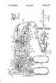
- FIG. 1is a schematic illustration of a breathing system showing a sectional view of a control means constructed according to the principles of this invention for regulating the flow of an oxygen enriched breathable fluid supplied to a recipient;
- FIG. 2is a sectional view of a distribution conduit for the breathing system taken along line 2--2 of FIG. 1;
- FIG. 3is a graph showing a typical pressure pattern measured in the nasal passage of a recipient during a breathing cycle.
- the breathing system 10shown in FIG. 1, has a control means 12 for regulating the communication of breathable fluid from either storage container 14 or 16 through a cannula means 18 to a recipient.
- the control means 12has a housing 24 with a supply passageway 26, which connects an operational switch means 20 with regulator means 22; a distribution passageway 30, which connects the regulator means 22 with plenum means 32; a control passageway 34, which connects the regulator means 22 with a wall means 36; a sensor passageway 38, which connects a sensor means 40 with the cannula means 18; a relief passageway 42, which connects the wall means 36 with the sensor means 40; an outlet passageway 44, which connects the plenum means 32 with the cannula means 18; and an aspirator passageway 46, which connects the sensor means 40 with the outlet passageway 44.
- the housing 24has a first entrance port 17 and a second entrance port 19 having threads thereon for attaching the first and second supply or storage containers 14 and 16 to the control means 12.
- Each of the supply containers 14 and 16have necks 21 and 221 on which O-ring seals 23 and 223 are located to engage the housing 24 and form a fluid tight seal.
- First and second pintles 25 and 29extend from the housing 24 to engage balls 27 and 31 in the necks 21 and 221 of storage or supply containers 14 and 16 to allow communication of the breathable fluid therein to flow into first and second branches 33 and 35 of the supply passageway 26.
- the operational switch means 20has a cylindrical body 37.
- the cylindrical body 37has axial passageway 39 connected to supply conduit 26 and a radial passageway 41.
- the radial passageway 41is adapted to be connected to the first and second branches 33 and 35.
- the cylindrical body 37has indicator indicia (OFF, 1,2) located thereon for informing the operator of the supply container which is connected to the supply conduit 26.
- a gage 43is also connected to the supply conduit 26 to inform the operator of the approximate quantity of oxygen enriched breathable fluid in the operational supply container.
- a low volume alarmis connected to the supply conduit 26 to warn the operator that the supply is reaching a low level and a change from one supply container to the other may be desirable.
- the supply conduit 26terminates in a high pressure chamber 66 adjacent the regulator means 22. Communication from the high pressure chamber 66 through bore 64 is entirely controlled by the regulator means 22.
- the regulator means 22has a diaphragm 48 which divides a cavity in the housing 24 into an atmospheric chamber 50 and a flow-through-chamber 52.
- a spring retainer 54located in the atmospheric chamber 50, is connected to a plate 56, in the flow-through-chamber 52, by a rivet 58.
- the center portion of the diaphragm 48is sandwiched between the spring retainer 54, and the plate 56, by the rivet 58.
- the plate 56has a projection 62 which extends into bore 64.
- a ball 68 located in the high pressure chamber 66is urged toward seat 70 associated with bore 64 by spring 72 to prevent communication between the high pressure chamber 66 and the flow-through-chamber 52.
- a spring 60urges projection 62 toward the ball 68.
- spring 60moves the diaphragm 48 toward the flow-through-chamber 52 causing the projection 62 to unseat ball 68 from seat 70 and allows communication of the breathable fluid from the high pressure chamber 66.
- the diaphragm 48moves toward the atmospheric chamber and allows spring 72 to urge ball 68 toward seat 70 and thereby interrupt the communication of breathable fluid through bore 64.
- the distribution passage 30connects the flow-through-chamber 52 to a selector valve means 74 which is associated with the plenum means 32.
- the selector valve means 74has a cylindrical body 76.
- the cylindrical body 76has an axial bore 78 connected to the distribution passageway 30 and a radial bore 80 for distribution of the oxygen enriched breathable fluid into the storage chamber 82 of the plenum means 32.
- the housing 24has a series of detents 84, 86, 88 and 90 adjacent the cylindrical body 76.
- a ball 92 in the cylindrical body 76is biased into a selected detent 84, 86, 88 or 90 to prevent the cylindrical body 76 from rotating after an operator has selected a desired flow rate from the flow-through-chamber 52.
- the housing 24has a first passage 96 with a first orifice 98, a second passage 100 with a second orifice 102, a third passage 104 with a third orifice 106, and a fourth passage 108 with a fourth orifice 110 through which the radial bore 80 of the selector valve means 74 is connected with the storage chamber 82.
- the orifices 98, 102, 106 and 110are circular. The size of each orifice will vary from each other as square of the radius in accordance with the following formula:
- QQuantity of fluid in liters/min.
- VVelocity of the fluid
- the flow rate into the storage chamber 82 of the plenum means 32is directly related to the radius of the orifice to which the radial bore 80 is connected. Since the storage chamber 82 retains a fixed quantity of the oxygen enriched breathable fluid for each flow rate selected, the communication of oxygen enriched breathable fluid from the storage chamber 82 is regulated by a first wall means 36 of a control means 111.
- the control means 111has first wall means 36 with a diaphragm 116.
- the diaphragm 116divides a cavity in the housing 24 into a control chamber 112 and a distribution chamber 114.
- Control passageway 34connects control chamber 112 with the flow-through-chamber 52.
- An orifice 118controls the flow rate of the oxygen enriched breathable fluid present in the control passageway 34 into the control chamber 112.
- the housing 24has a passage 122 which connects the storage chamber 82 with the distribution chamber 114.
- An annular projection 120surrounds the passage 122 to provide a seat for diaphragm 116.
- the diaphragm 116engages projection 120 to prevent flow of the oxygen enriched breathable fluid from storage chamber 82 into the distribution chamber 114 during the exhalation phase of the breathing cycle of a recipient.
- the distribution chamber 114is directly connected to the outlet passage 44 for communicating the oxygen enriched breathable fluid in the storage chamber 82 to the recipient upon movement of the wall means 36 away from passage 122.
- the operation of the wall means 36is controlled by sensor means 40.
- Sensor means 40responds to the inhalation and exhalation phases in a breathing cycle of a recipient.
- the sensor means 40has a first diaphragm 124, which is attached to the housing 24 to establish a sensing chamber 126, and a second diaphragm 128 which is attached to the housing 24 to establish an atmospheric chamber 130.
- a first backing plate 132is attached to the first diaphragm 124 and a second backing plate 134 is attached to the second diaphragm 128.
- a conduit 140is attached to the housing 24 for extending the relief passageway 42 into the center of the constant volume relief chamber 138.
- the conduit 140has an end section 142 with a face 144 parallel to the center surface of the first diaphragm 124.
- a spring 125acts on the first backing plate 132 to move the face 127 against the face 144 of the conduit extension 142 to separate the constant volume relief chamber 138 from relief passageway 42.
- the constant volume relief chamber 138is connected to the output passageway 44 through relief passageway 46.
- the relief passageway 46has a relief chamber 146 located therein adjacent a venturi section 148 in the outlet passageway 44.
- a check valve means 156is located in the relief chamber 146.
- the check valve means 156has a disc 150 which is urged toward seat 152 by a spring 154.
- the spring 154has sufficient resiliency to move the disc 150 onto seat 152 during an exhalation phase while allowing substantially free flow during the inhalation phase of a breathing cycle.
- the housing 24has a first nipple 155 with an annular shoulder 157 located thereon for attaching a sensing conduit 158 to the sensing passageway 38 and a second nipple 160 with an annular shoulder 162 located thereon for attaching a distribution conduit 164 to the outlet passageway 44.
- a first coupling 166joins the individual sensing conduit 158 and distribution 164 into a single structure conduit 170 as shown in FIG. 2.
- the length of the single structure conduit 170can be varied to meet the needs of the recipient.
- a second coupling 168divides the sensing conduit 158, into a first branch 180 and a second branch 182, and the distribution conduit 164 into a first branch 184 and a second branch 186.
- the first branch 184 of the distribution conduit 164is connected to a first tubular radial projection 174 extending from the cylindrical body 170 of the cannula means 18.
- the first branch 180 of the sensing conduit 158has an extension 178 which is located in the first tubular radial projection 174.
- the second branch 186 of the distribution conduit 164is connected to a second radial projection 176 extending from the cylindrical body 170 of the cannula means 18.
- the second branch 182 of the sensing conduit 158has an extension 188 which is located in the second tubular radial projection 176.
- the first and second tubular radial projections 174 and 176are adapted to be inserted into the nasal cavity of the recipient.
- an operatormoves switch means 20 to an ON position, as shown in FIG. 1, to a position where indicia 1 is aligned with arrow 45.
- Breathable fluid in storage container 14can now flow into the first branch 33, through radial passageway 41, and into the axial passageway 39 for communication into the supply conduit 26.
- Pointer 47 on gage 43indicates the quantity of the breathable fluid in the storage container 14. If the quantity of breathable fluid in the storage container 14 is below a predetermined value, the operator moves the cylindrical body to a second position where indicia 2 is aligned with arrow 45 to allow communication of breathable fluid from the second container 16.
- the high pressure oxygen enriched breathable fluid in the supply conduit 26is communicated into the high pressure chamber 66.
- spring 60moves ball 68 away from seat 70 and allows the high pressure breathable fluid to enter the flow-through-chamber 52.
- the pressure acting on diaphragmovercomes the spring 60 and moves the projection 62 out of engagement with ball 68.
- spring 72urges ball 68 against seat 70 to seal the high pressure chamber 66.
- the oxygen enriched breathable fluid located in the flow-through-chamber 52is simultaneously communicated through distribution passageway 30 going to the selector valve means 74 and through control passageway 34 going to the first wall means 36 of the control means 111. Thereafter, the operator, depending upon the recipient's need for oxygen enriched breathable fluid, moves the cylindrical body 76 to align radial passage 80 with the appropriate flow passage, shown in FIG. 1 as passage 100.
- the oxygen enriched breathable fluidcontinually flows from the distribution passage 30, through axial passage 78, out the radial passage 80, past orifice 102 and into the storage chamber 82.
- oxygen enriched breathable fluidflows in control passageway 34, through orifice 118 and into control chamber 112.
- the oxygen enriched breathable fluidacts on diaphragm 116 to move face 117 against face 120 and seal passage 122. With passage 122 sealed, a fixed quantity of breathable fluid is retained in storage chamber 82.
- the cannula means 18can be connected to the recipient.
- the first and second tubular projections 174 and 176are inserted in the nasal cavities of the recipient. As the recipient breathes, a pressure pattern 175 as indicated in FIG. 3 is sensed.
- a negative pressureshown below base line 177, occurs in the nasal cavity.
- This negative pressureas sensed by extensions 178 and 188 of the sensing conduit 158 is communicated into sensing chamber 126.
- a pressure differentialoccurs across the first and second diaphragms 124 and 128 which overcomes spring 125.
- This pressure differentialmoves the face 127 of the first diaphragm 124 away from the end 144 of the relief passage extension 140 to allow the pressurized of the oxygen enriched breathable fluid in the control chamber 112 to flow into the constant volume chamber 138.
- the pressurized of the oxygen enriched breathable fluid in storage chamber 82moves face 117 away from seat 122.
- the oxygen enriched breathable fluidflows in the outlet passage 44, past venturi 148 and into the distribution conduit 164 for delivery through the first and second branches 184 and 186 to the recipient.
- spring 60moves the diaphragm 48 toward the flow-through-chamber 52 and brings projection 64 into engagement with ball 68. Further movement of the diaphragm 48 causes the projection 64 to move ball 68 away from seat 70 and allows high pressure oxygen enriched breathable fluid to enter into and raise the pressure in the flow-through-chamber 52.
- spring 60is overcome, and projection 62 moves away from ball 68. With the projection 62 out of engagement with ball 68, spring 72 seats the ball 68 on seat 70 and interrupts the communication between the high pressure chamber 66 and the flow-through-chamber 52. This type of modulation automatically occurs whenever the pressure in the flow-through-chamber 52 drops below the preselected value.
- a positive pressureshown in FIG. 3 as above line 177, occurs in the exhalation phase of the breathing cycle.
- This positive pressureis communicated to the sensing chamber 126 to eliminate the pressure differential across the first and second diaphragms 124 and 128.
- the elimination of the pressure differentialallows spring 125 to move face 127 into engagement with face 144 of the conduit extension 140 and terminate communication between the control chamber 112 and the constant volume chamber 138.
- With the relief passage extension 140 sealed oxygen enriched breathable fluid present in the control passageway 34is directed into the control chamber 112.
- oxygen enriched breathable fluid in the control chamber 112the pressure acts on diaphragm 116 to move face 117 against seat 120. With face 117 seated on seat 120, the flow of the oxygen enriched breathable fluid into the storage chamber 82 continues until a fixed volume of breathable fluid at a predetermined pressure is retained.
- a slight pauseoccurs in the breathing cycle of human beings. During this pause segment, the pressure in the sensing chamber 126 approaches the pressure in chamber 130. Thereafter, the inhalation phase of the next breathing cycle begins and a negative pressure transmitted to the sensing chamber 126 again creates the operational pressure differential.
- the operational pressure differentialcontrols the position of the diaphragm 116 of the wall means 36. When the wall means 36 moves, the fixed volume of oxygen enriched breathable fluid is immediately communicated to the recipient through the outlet passage 44 and supply conduit 164. This cycle is repeated in each breathing cycle as long as the oxygen enriched breathable fluid is available in the supply containers 14 and 16.
Landscapes
- Health & Medical Sciences (AREA)
- Pulmonology (AREA)
- Emergency Medicine (AREA)
- Biomedical Technology (AREA)
- Engineering & Computer Science (AREA)
- Anesthesiology (AREA)
- Heart & Thoracic Surgery (AREA)
- Hematology (AREA)
- Life Sciences & Earth Sciences (AREA)
- Animal Behavior & Ethology (AREA)
- General Health & Medical Sciences (AREA)
- Public Health (AREA)
- Veterinary Medicine (AREA)
- Otolaryngology (AREA)
- Respiratory Apparatuses And Protective Means (AREA)
Abstract
Description
Q = V A
Q = V π Γ.sup.2
Claims (14)
Priority Applications (7)
| Application Number | Priority Date | Filing Date | Title |
|---|---|---|---|
| US05/671,195US4054133A (en) | 1976-03-29 | 1976-03-29 | Control for a demand cannula |
| CA272,914ACA1079154A (en) | 1976-03-29 | 1977-03-01 | Control for a demand cannula |
| GB12031/77AGB1534247A (en) | 1976-03-29 | 1977-03-22 | Control device for a breathing system |
| FR7708493AFR2346025A1 (en) | 1976-03-29 | 1977-03-22 | RESPIRATORY SYSTEM |
| DE19772713649DE2713649A1 (en) | 1976-03-29 | 1977-03-28 | VENTILATION SYSTEM |
| JP3407777AJPS52118995A (en) | 1976-03-29 | 1977-03-29 | Respirator |
| CA335,201ACA1087486A (en) | 1976-03-29 | 1979-09-07 | Control for a demand cannula |
Applications Claiming Priority (1)
| Application Number | Priority Date | Filing Date | Title |
|---|---|---|---|
| US05/671,195US4054133A (en) | 1976-03-29 | 1976-03-29 | Control for a demand cannula |
Publications (1)
| Publication Number | Publication Date |
|---|---|
| US4054133Atrue US4054133A (en) | 1977-10-18 |
Family
ID=24693513
Family Applications (1)
| Application Number | Title | Priority Date | Filing Date |
|---|---|---|---|
| US05/671,195Expired - LifetimeUS4054133A (en) | 1976-03-29 | 1976-03-29 | Control for a demand cannula |
Country Status (6)
| Country | Link |
|---|---|
| US (1) | US4054133A (en) |
| JP (1) | JPS52118995A (en) |
| CA (1) | CA1079154A (en) |
| DE (1) | DE2713649A1 (en) |
| FR (1) | FR2346025A1 (en) |
| GB (1) | GB1534247A (en) |
Cited By (128)
| Publication number | Priority date | Publication date | Assignee | Title |
|---|---|---|---|---|
| US4163448A (en)* | 1975-09-15 | 1979-08-07 | La Spirotechnique, Industrielle Et Commerciale | Breathing apparatus |
| US4374521A (en)* | 1980-09-12 | 1983-02-22 | Puritan-Bennett Corporation | Squeeze bag type resuscitator apparatus |
| US4414982A (en)* | 1980-11-26 | 1983-11-15 | Tritec Industries, Inc. | Apneic event detector and method |
| US4436090A (en) | 1979-01-22 | 1984-03-13 | Darling Phillip H | Piston actuated, pilot valve operated breathing regulator |
| WO1984001295A1 (en)* | 1982-10-01 | 1984-04-12 | Robert E Phillips | Oxygen therapy method and apparatus |
| WO1984001293A1 (en)* | 1982-10-01 | 1984-04-12 | Robert E Phillips | Oxygen delivery apparatus |
| WO1984002080A1 (en)* | 1982-12-03 | 1984-06-07 | Tritec Ind Inc | Respirating gas supply method and apparatus therefor |
| US4457303A (en)* | 1980-11-26 | 1984-07-03 | Tritec Industries, Inc. | Respirating gas supply control method and apparatus therefor |
| US4575042A (en)* | 1984-08-17 | 1986-03-11 | Associates Of Dallas | Pneumatically amplified conservation valve |
| US4612928A (en)* | 1984-08-28 | 1986-09-23 | Tiep Brian L | Method and apparatus for supplying a gas to a body |
| WO1987002590A1 (en)* | 1985-11-05 | 1987-05-07 | Shattuck, Leonard, L. | Positive-flow, demand responsive, respiratory regulator |
| US4705034A (en)* | 1985-10-02 | 1987-11-10 | Perkins Warren E | Method and means for dispensing respirating gases by effecting a known displacement |
| US4706664A (en)* | 1986-04-11 | 1987-11-17 | Puritan-Bennett Corporation | Inspiration oxygen saver |
| US4932401A (en)* | 1988-04-01 | 1990-06-12 | Perkins Warren E | Two-gas variable ratio, variable dose, metering system and method of use |
| US4989599A (en)* | 1989-01-26 | 1991-02-05 | Puritan-Bennett Corporation | Dual lumen cannula |
| US5005570A (en)* | 1985-10-02 | 1991-04-09 | Perkins Warren E | Method and means for dispensing respirating gases by effecting a known displacement |
| WO1991006335A1 (en)* | 1989-11-01 | 1991-05-16 | Puritan-Bennett | Pneumatic demand oxygen valve |
| DE4007274A1 (en)* | 1990-03-08 | 1991-09-12 | Planeta Hausgeraete | Cartridge for dispensing oxygen - comprises closed pipe coil in housing with opening tool |
| US5099836A (en)* | 1987-10-05 | 1992-03-31 | Hudson Respiratory Care Inc. | Intermittent oxygen delivery system and cannula |
| US5099837A (en)* | 1990-09-28 | 1992-03-31 | Russel Sr Larry L | Inhalation-based control of medical gas |
| US5137017A (en)* | 1989-04-13 | 1992-08-11 | Salter Labs | Demand oxygen system |
| US5165397A (en)* | 1988-12-15 | 1992-11-24 | Arp Leon J | Method and apparatus for demand oxygen system monitoring and control |
| USH1282H (en) | 1990-02-05 | 1994-02-01 | The United States Of America As Represented By The Secretary Of The Army | Fluidic volume-cycled respirator |
| US5335656A (en)* | 1988-04-15 | 1994-08-09 | Salter Laboratories | Method and apparatus for inhalation of treating gas and sampling of exhaled gas for quantitative analysis |
| US5360000A (en)* | 1987-03-19 | 1994-11-01 | Puritan-Bennett Corporation | Pneumatic demand oxygen valve |
| US5443062A (en)* | 1993-11-23 | 1995-08-22 | Hayes; Jeffrey P. | Load activated oxygen delivery system |
| US5558086A (en)* | 1992-12-16 | 1996-09-24 | Freedom Air Services | Method and apparatus for the intermittent delivery of oxygen therapy to a person |
| WO1997011734A1 (en)* | 1995-09-28 | 1997-04-03 | Nellcor Puritan Bennett Incorporated | Oxygen-conserving regulator assembly |
| US5666945A (en)* | 1995-06-07 | 1997-09-16 | Salter Labs | Pneumatically-operated gas demand apparatus |
| USD392036S (en) | 1995-06-09 | 1998-03-10 | Draeger Limited | Combined breathable gas container and carrying harness for a self-contained breathing apparatus |
| US5865174A (en)* | 1996-10-29 | 1999-02-02 | The Scott Fetzer Company | Supplemental oxygen delivery apparatus and method |
| US5881725A (en)* | 1997-08-19 | 1999-03-16 | Victor Equipment Company | Pneumatic oxygen conserver |
| WO1999022795A1 (en)* | 1997-11-04 | 1999-05-14 | Protector Technologies B.V. | Oxygen therapy apparatus |
| WO2000059566A1 (en)* | 1999-04-07 | 2000-10-12 | Event Medical Limited | Breathing apparatus |
| WO2000064522A1 (en)* | 1999-04-26 | 2000-11-02 | Veritek Ngv, Canada, Corporation | Treatment of carbon monoxide poisoning |
| WO2001041857A1 (en)* | 1999-12-13 | 2001-06-14 | Techwood As | A valve device for controlled supply of a pressure fluid |
| US6364161B1 (en) | 2000-09-27 | 2002-04-02 | Victor Equipment Company | Oxygen conserver |
| US6371114B1 (en) | 1998-07-24 | 2002-04-16 | Minnesota Innovative Technologies & Instruments Corporation | Control device for supplying supplemental respiratory oxygen |
| US6394088B1 (en)* | 1998-11-06 | 2002-05-28 | Mark R. Frye | Oxygen-delivery system with portable oxygen meter |
| GB2370511A (en)* | 2000-09-11 | 2002-07-03 | Western Scott Fetzer Company | Oxygen conserver |
| US6532958B1 (en) | 1997-07-25 | 2003-03-18 | Minnesota Innovative Technologies & Instruments Corporation | Automated control and conservation of supplemental respiratory oxygen |
| US20030140924A1 (en)* | 2001-11-06 | 2003-07-31 | Aylsworth Alonzo C. | Therapeutic gas conserver and control |
| US6626668B2 (en)* | 2001-01-05 | 2003-09-30 | Kaltenbach & Voigt Gmbh & Co. | Medical or dental-medical apparatus having a delivery line for a liquid |
| US6752152B2 (en)* | 2001-10-19 | 2004-06-22 | Precision Medical, Inc. | Pneumatic oxygen conserving device |
| US20040154620A1 (en)* | 2001-10-19 | 2004-08-12 | Gale Peter P. | Pneumatic oxygen conserving device |
| USD495049S1 (en) | 2003-06-24 | 2004-08-24 | Taga Medical Technologies, Inc | Oxygen conserving regulator |
| EP1462140A1 (en)* | 2003-03-26 | 2004-09-29 | Taema | First aid portable ventilator |
| US20050005942A1 (en)* | 2003-07-09 | 2005-01-13 | Airmatrix Technologies, Inc. | Method and system for measuring airflow of nares |
| US20050072306A1 (en)* | 2003-10-07 | 2005-04-07 | Deane Geoffrey Frank | Portable gas fractionalization system |
| US20050092321A1 (en)* | 2003-10-29 | 2005-05-05 | Airmatrix Technologies, Inc. | Method and system of sensing airflow and delivering therapeutic gas to a patient |
| US20050121033A1 (en)* | 1998-02-25 | 2005-06-09 | Ric Investments, Llc. | Respiratory monitoring during gas delivery |
| US6910482B2 (en) | 2001-10-19 | 2005-06-28 | Chart Inc. | Self-calibrating supplemental oxygen delivery system |
| US20050257788A1 (en)* | 2004-05-20 | 2005-11-24 | Acoba, Llc | Method and system to determine nasal resistance to airflow |
| US20060005842A1 (en)* | 2004-07-09 | 2006-01-12 | Rashad M A | Nasal pressure sensor oxygen therapy device |
| US20060060198A1 (en)* | 2004-09-17 | 2006-03-23 | Acoba, Llc | Method and system of scoring sleep disordered breathing |
| US20060086359A1 (en)* | 2004-10-22 | 2006-04-27 | Taga Medical Technologies, Inc. | Dual scale control knob for an oxygen conserving regulator |
| US7066985B2 (en) | 2003-10-07 | 2006-06-27 | Inogen, Inc. | Portable gas fractionalization system |
| US20060169281A1 (en)* | 2005-02-03 | 2006-08-03 | Aylsworth Alonzo C | Continuous flow selective delivery of therapeutic gas |
| US20060174885A1 (en)* | 2005-02-08 | 2006-08-10 | Acoba, Llc | Method and related system to control applied pressure in CPAP systems |
| US20070017520A1 (en)* | 2001-10-19 | 2007-01-25 | Gale Peter P | Oxygen delivery apparatus |
| US20070113856A1 (en)* | 2005-11-22 | 2007-05-24 | General Electric Company | Respiratory monitoring with cannula receiving respiratory airflows |
| US20070113850A1 (en)* | 2005-11-22 | 2007-05-24 | General Electric Company | Respiratory monitoring with cannula receiving respiratory airflows and differential pressure transducer |
| US20070113848A1 (en)* | 2005-11-22 | 2007-05-24 | General Electric Company | Respiratory monitoring with cannula receiving respiratory airflows and exhaled gases |
| US20070113847A1 (en)* | 2005-11-22 | 2007-05-24 | General Electric Company | Respiratory monitoring with cannula receiving first respiratory airflows and second respiratory airflows |
| US20070125380A1 (en)* | 2005-11-22 | 2007-06-07 | General Electric Company | Respiratory monitoring with differential pressure transducer |
| US20070135757A1 (en)* | 2005-12-12 | 2007-06-14 | Acker Jaron M | Multiple lumen monitored drug delivery nasal cannula system |
| US7328703B1 (en)* | 2004-08-25 | 2008-02-12 | Tiep Brian L | Oxygen delivery cannula system that improves the effectiveness of alveolar oxygenation |
| US20080078393A1 (en)* | 2005-11-22 | 2008-04-03 | General Electric Company | Respiratory monitoring with cannula receiving respiratory airflows, differential pressure transducer, and ventilator |
| US20080078407A1 (en)* | 2006-09-28 | 2008-04-03 | Nellcor Puritan Bennett Incorporated | System and method for providing support for a breathing passage |
| US20080190436A1 (en)* | 2006-08-04 | 2008-08-14 | Jaffe Michael B | Nasal and oral patient interface |
| US20080190429A1 (en)* | 2005-03-02 | 2008-08-14 | Integral Orthopedics Inc. | Conserving Device for Breathable Gas |
| US20080202519A1 (en)* | 2007-02-23 | 2008-08-28 | General Electric Company | Setting mandatory mechanical ventilation parameters based on patient physiology |
| US20080202518A1 (en)* | 2007-02-23 | 2008-08-28 | General Electric Company | Setting mandatory mechanical ventilation parameters based on patient physiology |
| US20080202522A1 (en)* | 2007-02-23 | 2008-08-28 | General Electric Company | Setting mandatory mechanical ventilation parameters based on patient physiology |
| US20080202517A1 (en)* | 2007-02-23 | 2008-08-28 | General Electric Company | Setting madatory mechanical ventilation parameters based on patient physiology |
| US20080202520A1 (en)* | 2007-02-23 | 2008-08-28 | General Electric Company | Setting mandatory mechanical ventilation parameters based on patient physiology |
| US20080230061A1 (en)* | 2007-03-23 | 2008-09-25 | General Electric Company | Setting expiratory time in mandatory mechanical ventilation based on a deviation from a stable condition of end tidal gas concentrations |
| US20080230060A1 (en)* | 2007-03-23 | 2008-09-25 | General Electric Company | Setting inspiratory time in mandatory mechanical ventilation based on patient physiology, such as when tidal volume is inspired |
| US20080230064A1 (en)* | 2007-03-23 | 2008-09-25 | General Electric Company | Setting inspiratory time in mandatory mechanical ventilation based on patient physiology, such as when forced inhalation flow ceases |
| US20080230063A1 (en)* | 2007-03-23 | 2008-09-25 | General Electric Company | Setting inspiratory time in mandatory mechanical ventilation based on patient physiology, such as forced inhalation time |
| US7438745B2 (en) | 2003-10-07 | 2008-10-21 | Inogen, Inc. | Portable gas fractionalization system |
| US7448594B2 (en) | 2004-10-21 | 2008-11-11 | Ameriflo, Inc. | Fluid regulator |
| US20090199855A1 (en)* | 2004-11-01 | 2009-08-13 | Davenport James M | System and method for conserving oxygen delivery while maintaining saturation |
| US7617826B1 (en) | 2004-02-26 | 2009-11-17 | Ameriflo, Inc. | Conserver |
| US7686870B1 (en) | 2005-12-29 | 2010-03-30 | Inogen, Inc. | Expandable product rate portable gas fractionalization system |
| WO2011015826A1 (en)* | 2009-08-07 | 2011-02-10 | Kind Consumer Limited | An inhaler |
| US7922789B1 (en) | 2003-10-07 | 2011-04-12 | Inogen, Inc. | Portable gas fractionalization system |
| US20110114098A1 (en)* | 2007-11-16 | 2011-05-19 | Mcauley Alastair Edwin | Nasal pillows with high volume bypass flow and method of using same |
| US20110253147A1 (en)* | 2010-04-19 | 2011-10-20 | Gusky Michael H | Breathing apparatus |
| US8136527B2 (en) | 2003-08-18 | 2012-03-20 | Breathe Technologies, Inc. | Method and device for non-invasive ventilation with nasal interface |
| US8146592B2 (en) | 2004-02-26 | 2012-04-03 | Ameriflo, Inc. | Method and apparatus for regulating fluid flow or conserving fluid flow |
| CN102481425A (en)* | 2009-04-02 | 2012-05-30 | 呼吸科技公司 | Methods, systems and apparatus for non-invasive open ventilation using a gas delivery nozzle within an outer tube |
| US8381729B2 (en) | 2003-06-18 | 2013-02-26 | Breathe Technologies, Inc. | Methods and devices for minimally invasive respiratory support |
| US8418694B2 (en) | 2003-08-11 | 2013-04-16 | Breathe Technologies, Inc. | Systems, methods and apparatus for respiratory support of a patient |
| US20130092165A1 (en)* | 2011-09-26 | 2013-04-18 | Anthony David Wondka | Nasal Ventilation Cannula System and Methods |
| US20130104901A1 (en)* | 2005-09-12 | 2013-05-02 | Mergenet Medical, Inc. | High Flow Therapy Artificial Airway Interfaces and Related Methods |
| US8567399B2 (en) | 2007-09-26 | 2013-10-29 | Breathe Technologies, Inc. | Methods and devices for providing inspiratory and expiratory flow relief during ventilation therapy |
| US8677999B2 (en) | 2008-08-22 | 2014-03-25 | Breathe Technologies, Inc. | Methods and devices for providing mechanical ventilation with an open airway interface |
| US8770193B2 (en) | 2008-04-18 | 2014-07-08 | Breathe Technologies, Inc. | Methods and devices for sensing respiration and controlling ventilator functions |
| US8770199B2 (en) | 2012-12-04 | 2014-07-08 | Ino Therapeutics Llc | Cannula for minimizing dilution of dosing during nitric oxide delivery |
| US8776793B2 (en) | 2008-04-18 | 2014-07-15 | Breathe Technologies, Inc. | Methods and devices for sensing respiration and controlling ventilator functions |
| US20140318536A1 (en)* | 2005-09-12 | 2014-10-30 | Mergenet Medicial, Inc. | Nasal cannula |
| US8925545B2 (en) | 2004-02-04 | 2015-01-06 | Breathe Technologies, Inc. | Methods and devices for treating sleep apnea |
| US8939152B2 (en) | 2010-09-30 | 2015-01-27 | Breathe Technologies, Inc. | Methods, systems and devices for humidifying a respiratory tract |
| US8955518B2 (en) | 2003-06-18 | 2015-02-17 | Breathe Technologies, Inc. | Methods, systems and devices for improving ventilation in a lung area |
| US8985099B2 (en) | 2006-05-18 | 2015-03-24 | Breathe Technologies, Inc. | Tracheostoma spacer, tracheotomy method, and device for inserting a tracheostoma spacer |
| US20150083123A1 (en)* | 2012-03-28 | 2015-03-26 | Robert Tero | Nasal Cannula with Pressure Monitoring |
| US9132250B2 (en) | 2009-09-03 | 2015-09-15 | Breathe Technologies, Inc. | Methods, systems and devices for non-invasive ventilation including a non-sealing ventilation interface with an entrainment port and/or pressure feature |
| US9352115B1 (en)* | 2011-11-18 | 2016-05-31 | Capnia, Inc. | Respiratory ventilation system with gas sparing valve having optional CPAP mode and mask for use with same |
| US20170065790A1 (en)* | 2015-09-04 | 2017-03-09 | Air Liquide Advanced Technologies U.S. LP | Gas demand device, method of installation, gas delivery system, and method of use |
| US9795756B2 (en) | 2012-12-04 | 2017-10-24 | Mallinckrodt Hospital Products IP Limited | Cannula for minimizing dilution of dosing during nitric oxide delivery |
| US20180043123A1 (en)* | 2016-01-18 | 2018-02-15 | Baiping Lei | Nasal breathing apparatus and method with multifunction |
| US9962512B2 (en) | 2009-04-02 | 2018-05-08 | Breathe Technologies, Inc. | Methods, systems and devices for non-invasive ventilation including a non-sealing ventilation interface with a free space nozzle feature |
| US10058668B2 (en) | 2007-05-18 | 2018-08-28 | Breathe Technologies, Inc. | Methods and devices for sensing respiration and providing ventilation therapy |
| US10099028B2 (en) | 2010-08-16 | 2018-10-16 | Breathe Technologies, Inc. | Methods, systems and devices using LOX to provide ventilatory support |
| US10226591B1 (en)* | 2012-09-25 | 2019-03-12 | Cleveland Medical Devices Inc. | Methods and devices for carbon dioxide-based sleep disorder therapy |
| US10252020B2 (en) | 2008-10-01 | 2019-04-09 | Breathe Technologies, Inc. | Ventilator with biofeedback monitoring and control for improving patient activity and health |
| US10792449B2 (en) | 2017-10-03 | 2020-10-06 | Breathe Technologies, Inc. | Patient interface with integrated jet pump |
| US10967203B1 (en) | 2018-10-30 | 2021-04-06 | Neale Emerson | Oxygen delivery device |
| US20210128864A1 (en)* | 2019-11-06 | 2021-05-06 | Koninklijke Philips N.V. | Oxygen recovery during nasal therapy |
| US11154672B2 (en) | 2009-09-03 | 2021-10-26 | Breathe Technologies, Inc. | Methods, systems and devices for non-invasive ventilation including a non-sealing ventilation interface with an entrainment port and/or pressure feature |
| US11406783B2 (en)* | 2018-08-23 | 2022-08-09 | Baiping Lei | Nasal breathing apparatus and method for high-flow therapy and non-invasive ventilation |
| US11517701B1 (en) | 2018-10-30 | 2022-12-06 | Neale Emerson | Oxygen delivery device |
| US20230010959A1 (en)* | 2019-12-09 | 2023-01-12 | Safran Aerotechnics | Regulator assembly for an aircrew breathing mask |
| US20230041231A1 (en)* | 2019-12-09 | 2023-02-09 | Safran Aerotechnics | Control assembly for a breathing mask of an aircraft crew member |
| US11638798B2 (en)* | 2016-10-13 | 2023-05-02 | Vyaire Medical Capital, LLC | Nasal cannula systems and methods |
| US20240066248A1 (en)* | 2022-08-26 | 2024-02-29 | Dan Tatum | Medicinal Diffuser |
| US12178961B2 (en) | 2020-10-22 | 2024-12-31 | Hill-Rom Services Pte. Ltd. | Multifunctional ventilator interfaces |
Families Citing this family (9)
| Publication number | Priority date | Publication date | Assignee | Title |
|---|---|---|---|---|
| JPS58500005A (en)* | 1980-11-26 | 1983-01-06 | トリテツク インダストリ−ズ,インコ−ポレ−テツド | breathing apparatus |
| JPS598972A (en)* | 1982-07-07 | 1984-01-18 | 佐藤 暢 | Respiration synchronous type gas supply method and apparatus in open type respiratory system |
| FR2530148B1 (en)* | 1982-07-13 | 1985-11-29 | France Prod Oxygenes Co | DEVICE FOR THE TREATMENT OF PATIENT RESPIRATORY FAILURE |
| US4506667A (en)* | 1983-04-06 | 1985-03-26 | Figgie Int Inc | Self-contained ventilator/resuscitator |
| DE3412118A1 (en)* | 1984-03-31 | 1985-10-10 | Allihn & Co Sauerstoffgeräte, 8000 München | Respiratory phase controller |
| FR2573204B1 (en)* | 1984-11-13 | 1987-01-30 | Air Liquide | DETECTOR OF LOWER PRESSURES TO THE MM OF WATER |
| DE3900276A1 (en)* | 1989-01-07 | 1990-07-12 | Draegerwerk Ag | VENTILATOR WITH BREATHING CIRCUIT AND CONTROLLED FRESH GAS SUPPLY |
| DE29622321U1 (en)* | 1996-12-21 | 1997-03-06 | Medicap Medizintechnik GmbH, 35327 Ulrichstein | Device for dosed gas supply to users |
| JP3930595B2 (en)* | 1997-01-16 | 2007-06-13 | 株式会社群馬コイケ | Breathing synchronization device for piping terminals |
Citations (11)
| Publication number | Priority date | Publication date | Assignee | Title |
|---|---|---|---|---|
| US1309686A (en)* | 1919-07-15 | Anesthetic apparatus | ||
| US2121311A (en)* | 1934-04-05 | 1938-06-21 | Gasaccumulator Svenska Ab | Respiration apparatus |
| US3043302A (en)* | 1958-05-08 | 1962-07-10 | Oxy Gear Inc | Flow control unit for portable inhalators |
| US3114365A (en)* | 1958-07-16 | 1963-12-17 | Franz Frederick | Apparatus for pulmonary ventilation during anesthesia |
| US3333581A (en)* | 1964-03-27 | 1967-08-01 | Elbert W Robinson | Pulmonary resuscitator with electrical control system |
| US3400713A (en)* | 1966-10-12 | 1968-09-10 | James E. Finan | Apparatus for intermittently dispensing oxygen or other gas suitable for breathing |
| US3434471A (en)* | 1966-04-06 | 1969-03-25 | Smithkline Corp | Therapeutic intermittent positive pressure respirator |
| US3797803A (en)* | 1971-05-15 | 1974-03-19 | Toyota Motor Co Ltd | Control valve assembly for a gas passageway |
| US3830257A (en)* | 1971-06-22 | 1974-08-20 | Minerve Sa | Air-gas mixture metering device, notably for respiratory mask |
| US3853105A (en)* | 1971-12-16 | 1974-12-10 | P Kenagy | Insufflator gas flow device |
| US3913576A (en)* | 1973-11-06 | 1975-10-21 | Westinghouse Electric Corp | Breathing apparatus |
- 1976
- 1976-03-29USUS05/671,195patent/US4054133A/ennot_activeExpired - Lifetime
- 1977
- 1977-03-01CACA272,914Apatent/CA1079154A/ennot_activeExpired
- 1977-03-22FRFR7708493Apatent/FR2346025A1/enactiveGranted
- 1977-03-22GBGB12031/77Apatent/GB1534247A/ennot_activeExpired
- 1977-03-28DEDE19772713649patent/DE2713649A1/ennot_activeWithdrawn
- 1977-03-29JPJP3407777Apatent/JPS52118995A/enactivePending
Patent Citations (11)
| Publication number | Priority date | Publication date | Assignee | Title |
|---|---|---|---|---|
| US1309686A (en)* | 1919-07-15 | Anesthetic apparatus | ||
| US2121311A (en)* | 1934-04-05 | 1938-06-21 | Gasaccumulator Svenska Ab | Respiration apparatus |
| US3043302A (en)* | 1958-05-08 | 1962-07-10 | Oxy Gear Inc | Flow control unit for portable inhalators |
| US3114365A (en)* | 1958-07-16 | 1963-12-17 | Franz Frederick | Apparatus for pulmonary ventilation during anesthesia |
| US3333581A (en)* | 1964-03-27 | 1967-08-01 | Elbert W Robinson | Pulmonary resuscitator with electrical control system |
| US3434471A (en)* | 1966-04-06 | 1969-03-25 | Smithkline Corp | Therapeutic intermittent positive pressure respirator |
| US3400713A (en)* | 1966-10-12 | 1968-09-10 | James E. Finan | Apparatus for intermittently dispensing oxygen or other gas suitable for breathing |
| US3797803A (en)* | 1971-05-15 | 1974-03-19 | Toyota Motor Co Ltd | Control valve assembly for a gas passageway |
| US3830257A (en)* | 1971-06-22 | 1974-08-20 | Minerve Sa | Air-gas mixture metering device, notably for respiratory mask |
| US3853105A (en)* | 1971-12-16 | 1974-12-10 | P Kenagy | Insufflator gas flow device |
| US3913576A (en)* | 1973-11-06 | 1975-10-21 | Westinghouse Electric Corp | Breathing apparatus |
Cited By (209)
| Publication number | Priority date | Publication date | Assignee | Title |
|---|---|---|---|---|
| US4163448A (en)* | 1975-09-15 | 1979-08-07 | La Spirotechnique, Industrielle Et Commerciale | Breathing apparatus |
| US4436090A (en) | 1979-01-22 | 1984-03-13 | Darling Phillip H | Piston actuated, pilot valve operated breathing regulator |
| US4374521A (en)* | 1980-09-12 | 1983-02-22 | Puritan-Bennett Corporation | Squeeze bag type resuscitator apparatus |
| US4414982A (en)* | 1980-11-26 | 1983-11-15 | Tritec Industries, Inc. | Apneic event detector and method |
| US4457303A (en)* | 1980-11-26 | 1984-07-03 | Tritec Industries, Inc. | Respirating gas supply control method and apparatus therefor |
| WO1984001295A1 (en)* | 1982-10-01 | 1984-04-12 | Robert E Phillips | Oxygen therapy method and apparatus |
| WO1984001293A1 (en)* | 1982-10-01 | 1984-04-12 | Robert E Phillips | Oxygen delivery apparatus |
| GB2142545A (en)* | 1982-10-01 | 1985-01-23 | Phillips Robert E | Oxygen therapy method and apparatus |
| US4535767A (en)* | 1982-10-01 | 1985-08-20 | Tiep Brian L | Oxygen delivery apparatus |
| WO1984002080A1 (en)* | 1982-12-03 | 1984-06-07 | Tritec Ind Inc | Respirating gas supply method and apparatus therefor |
| US4461293A (en)* | 1982-12-03 | 1984-07-24 | Kircaldie, Randall, And Mcnab | Respirating gas supply method and apparatus therefor |
| US4575042A (en)* | 1984-08-17 | 1986-03-11 | Associates Of Dallas | Pneumatically amplified conservation valve |
| US4612928A (en)* | 1984-08-28 | 1986-09-23 | Tiep Brian L | Method and apparatus for supplying a gas to a body |
| US4705034A (en)* | 1985-10-02 | 1987-11-10 | Perkins Warren E | Method and means for dispensing respirating gases by effecting a known displacement |
| US5005570A (en)* | 1985-10-02 | 1991-04-09 | Perkins Warren E | Method and means for dispensing respirating gases by effecting a known displacement |
| WO1987002590A1 (en)* | 1985-11-05 | 1987-05-07 | Shattuck, Leonard, L. | Positive-flow, demand responsive, respiratory regulator |
| US4706664A (en)* | 1986-04-11 | 1987-11-17 | Puritan-Bennett Corporation | Inspiration oxygen saver |
| US5360000A (en)* | 1987-03-19 | 1994-11-01 | Puritan-Bennett Corporation | Pneumatic demand oxygen valve |
| US5099836A (en)* | 1987-10-05 | 1992-03-31 | Hudson Respiratory Care Inc. | Intermittent oxygen delivery system and cannula |
| US4932401A (en)* | 1988-04-01 | 1990-06-12 | Perkins Warren E | Two-gas variable ratio, variable dose, metering system and method of use |
| US5335656A (en)* | 1988-04-15 | 1994-08-09 | Salter Laboratories | Method and apparatus for inhalation of treating gas and sampling of exhaled gas for quantitative analysis |
| US5165397A (en)* | 1988-12-15 | 1992-11-24 | Arp Leon J | Method and apparatus for demand oxygen system monitoring and control |
| US4989599A (en)* | 1989-01-26 | 1991-02-05 | Puritan-Bennett Corporation | Dual lumen cannula |
| WO1992012751A1 (en)* | 1989-01-26 | 1992-08-06 | Puritan-Bennett Corporation | Dual lumen cannula |
| US5137017A (en)* | 1989-04-13 | 1992-08-11 | Salter Labs | Demand oxygen system |
| WO1991006335A1 (en)* | 1989-11-01 | 1991-05-16 | Puritan-Bennett | Pneumatic demand oxygen valve |
| USH1282H (en) | 1990-02-05 | 1994-02-01 | The United States Of America As Represented By The Secretary Of The Army | Fluidic volume-cycled respirator |
| DE4007274A1 (en)* | 1990-03-08 | 1991-09-12 | Planeta Hausgeraete | Cartridge for dispensing oxygen - comprises closed pipe coil in housing with opening tool |
| US5099837A (en)* | 1990-09-28 | 1992-03-31 | Russel Sr Larry L | Inhalation-based control of medical gas |
| US5558086A (en)* | 1992-12-16 | 1996-09-24 | Freedom Air Services | Method and apparatus for the intermittent delivery of oxygen therapy to a person |
| US5443062A (en)* | 1993-11-23 | 1995-08-22 | Hayes; Jeffrey P. | Load activated oxygen delivery system |
| US5666945A (en)* | 1995-06-07 | 1997-09-16 | Salter Labs | Pneumatically-operated gas demand apparatus |
| USD392036S (en) | 1995-06-09 | 1998-03-10 | Draeger Limited | Combined breathable gas container and carrying harness for a self-contained breathing apparatus |
| AU704860B2 (en)* | 1995-09-28 | 1999-05-06 | Nellcor Puritan Bennett Incorporated | Oxygen-conserving regulator assembly |
| WO1997011734A1 (en)* | 1995-09-28 | 1997-04-03 | Nellcor Puritan Bennett Incorporated | Oxygen-conserving regulator assembly |
| JP3386138B2 (en) | 1995-09-28 | 2003-03-17 | ネルコー ピューリタン ベネット インコーポレイテッド | Oxygen storage regulator device |
| US5865174A (en)* | 1996-10-29 | 1999-02-02 | The Scott Fetzer Company | Supplemental oxygen delivery apparatus and method |
| US20040159323A1 (en)* | 1997-07-25 | 2004-08-19 | Minnesota Innovative Technologies And Instruments | Control of respiratory oxygen delivery |
| US6561187B2 (en) | 1997-07-25 | 2003-05-13 | Minnesota Innovative Technologies & Instruments Corporation | Control of supplemental respiratory oxygen |
| US20060213519A1 (en)* | 1997-07-25 | 2006-09-28 | Minnesota Innovative Technologies And Instruments | Control of respiratory oxygen delivery |
| US7331343B2 (en) | 1997-07-25 | 2008-02-19 | Minnesota Innovative Technologies & Instruments Corporation (Miti) | Control of supplemental respiratory oxygen |
| US20030145852A1 (en)* | 1997-07-25 | 2003-08-07 | Minnesota Innovative Technologies And Instruments | Control of supplemental respiratory Oxygen |
| US6532958B1 (en) | 1997-07-25 | 2003-03-18 | Minnesota Innovative Technologies & Instruments Corporation | Automated control and conservation of supplemental respiratory oxygen |
| US5881725A (en)* | 1997-08-19 | 1999-03-16 | Victor Equipment Company | Pneumatic oxygen conserver |
| WO1999022795A1 (en)* | 1997-11-04 | 1999-05-14 | Protector Technologies B.V. | Oxygen therapy apparatus |
| US6568391B1 (en) | 1997-11-04 | 2003-05-27 | Protector Technologies, B.V. | Oxygen therapy apparatus |
| US20050121033A1 (en)* | 1998-02-25 | 2005-06-09 | Ric Investments, Llc. | Respiratory monitoring during gas delivery |
| US6371114B1 (en) | 1998-07-24 | 2002-04-16 | Minnesota Innovative Technologies & Instruments Corporation | Control device for supplying supplemental respiratory oxygen |
| US6394088B1 (en)* | 1998-11-06 | 2002-05-28 | Mark R. Frye | Oxygen-delivery system with portable oxygen meter |
| WO2000059566A1 (en)* | 1999-04-07 | 2000-10-12 | Event Medical Limited | Breathing apparatus |
| WO2000064522A1 (en)* | 1999-04-26 | 2000-11-02 | Veritek Ngv, Canada, Corporation | Treatment of carbon monoxide poisoning |
| US6718980B2 (en) | 1999-04-26 | 2004-04-13 | Veritek Ngv | Treatment of carbon monoxide poisoning |
| US7040320B2 (en)* | 1999-12-13 | 2006-05-09 | Techwood As | Valve device for controlled supply of a pressure fluid |
| WO2001041857A1 (en)* | 1999-12-13 | 2001-06-14 | Techwood As | A valve device for controlled supply of a pressure fluid |
| JP2003516202A (en)* | 1999-12-13 | 2003-05-13 | テックウッド・エーエス | Valve device for supply control of pressurized fluid |
| US20030127098A1 (en)* | 1999-12-13 | 2003-07-10 | Anders Fjeld | Valve device for controlled supply of a pressure fluid |
| GB2370511A (en)* | 2000-09-11 | 2002-07-03 | Western Scott Fetzer Company | Oxygen conserver |
| US6612307B2 (en)* | 2000-09-11 | 2003-09-02 | Western/Scott Fetzer Company | Oxygen conserver |
| US6364161B1 (en) | 2000-09-27 | 2002-04-02 | Victor Equipment Company | Oxygen conserver |
| US6626668B2 (en)* | 2001-01-05 | 2003-09-30 | Kaltenbach & Voigt Gmbh & Co. | Medical or dental-medical apparatus having a delivery line for a liquid |
| US20040154620A1 (en)* | 2001-10-19 | 2004-08-12 | Gale Peter P. | Pneumatic oxygen conserving device |
| US6752152B2 (en)* | 2001-10-19 | 2004-06-22 | Precision Medical, Inc. | Pneumatic oxygen conserving device |
| US7089938B2 (en)* | 2001-10-19 | 2006-08-15 | Precision Medical, Inc. | Pneumatic oxygen conserving device |
| US20070017520A1 (en)* | 2001-10-19 | 2007-01-25 | Gale Peter P | Oxygen delivery apparatus |
| US6910482B2 (en) | 2001-10-19 | 2005-06-28 | Chart Inc. | Self-calibrating supplemental oxygen delivery system |
| US20030140924A1 (en)* | 2001-11-06 | 2003-07-31 | Aylsworth Alonzo C. | Therapeutic gas conserver and control |
| US20040200477A1 (en)* | 2003-03-26 | 2004-10-14 | Christian Bleys | Portable assembly for emergency ventilation |
| FR2852854A1 (en)* | 2003-03-26 | 2004-10-01 | Taema | PORTABLE EMERGENCY VENTILATION KIT |
| EP1462140A1 (en)* | 2003-03-26 | 2004-09-29 | Taema | First aid portable ventilator |
| US8381729B2 (en) | 2003-06-18 | 2013-02-26 | Breathe Technologies, Inc. | Methods and devices for minimally invasive respiratory support |
| US8955518B2 (en) | 2003-06-18 | 2015-02-17 | Breathe Technologies, Inc. | Methods, systems and devices for improving ventilation in a lung area |
| USD495049S1 (en) | 2003-06-24 | 2004-08-24 | Taga Medical Technologies, Inc | Oxygen conserving regulator |
| US20050005942A1 (en)* | 2003-07-09 | 2005-01-13 | Airmatrix Technologies, Inc. | Method and system for measuring airflow of nares |
| US7066180B2 (en)* | 2003-07-09 | 2006-06-27 | Airmatrix Technologies, Inc. | Method and system for measuring airflow of nares |
| US8418694B2 (en) | 2003-08-11 | 2013-04-16 | Breathe Technologies, Inc. | Systems, methods and apparatus for respiratory support of a patient |
| US8573219B2 (en) | 2003-08-18 | 2013-11-05 | Breathe Technologies, Inc. | Method and device for non-invasive ventilation with nasal interface |
| US8136527B2 (en) | 2003-08-18 | 2012-03-20 | Breathe Technologies, Inc. | Method and device for non-invasive ventilation with nasal interface |
| US20050072306A1 (en)* | 2003-10-07 | 2005-04-07 | Deane Geoffrey Frank | Portable gas fractionalization system |
| US7922789B1 (en) | 2003-10-07 | 2011-04-12 | Inogen, Inc. | Portable gas fractionalization system |
| US7066985B2 (en) | 2003-10-07 | 2006-06-27 | Inogen, Inc. | Portable gas fractionalization system |
| US7135059B2 (en) | 2003-10-07 | 2006-11-14 | Inogen, Inc. | Portable gas fractionalization system |
| US7438745B2 (en) | 2003-10-07 | 2008-10-21 | Inogen, Inc. | Portable gas fractionalization system |
| US7730887B2 (en) | 2003-10-07 | 2010-06-08 | Inogen, Inc. | Portable gas fractionalization system |
| US7753996B1 (en) | 2003-10-07 | 2010-07-13 | Inogen, Inc. | Portable gas fractionalization system |
| WO2005044331A3 (en)* | 2003-10-29 | 2006-03-09 | Airmatrix Technologies Inc | Method and system of sensing a patient’s airflow |
| US7007692B2 (en)* | 2003-10-29 | 2006-03-07 | Airmatrix Technologies, Inc. | Method and system of sensing airflow and delivering therapeutic gas to a patient |
| EP1680164A4 (en)* | 2003-10-29 | 2008-06-11 | Airmatrix Technologies Inc | Method and system of sensing a patient's airflow |
| US20050092321A1 (en)* | 2003-10-29 | 2005-05-05 | Airmatrix Technologies, Inc. | Method and system of sensing airflow and delivering therapeutic gas to a patient |
| US8925545B2 (en) | 2004-02-04 | 2015-01-06 | Breathe Technologies, Inc. | Methods and devices for treating sleep apnea |
| US7617826B1 (en) | 2004-02-26 | 2009-11-17 | Ameriflo, Inc. | Conserver |
| US8230859B1 (en) | 2004-02-26 | 2012-07-31 | Ameriflo, Inc. | Method and apparatus for regulating fluid |
| US8146592B2 (en) | 2004-02-26 | 2012-04-03 | Ameriflo, Inc. | Method and apparatus for regulating fluid flow or conserving fluid flow |
| US7213594B2 (en) | 2004-05-20 | 2007-05-08 | Acoba, L.L.C. | Method and system to determine nasal resistance to airflow |
| US20070186929A1 (en)* | 2004-05-20 | 2007-08-16 | Acoba, L.L.C. | Method and System to Determine Nasal Resistance to Airflow |
| US20050257788A1 (en)* | 2004-05-20 | 2005-11-24 | Acoba, Llc | Method and system to determine nasal resistance to airflow |
| US7013898B2 (en)* | 2004-07-09 | 2006-03-21 | Praxair Technology, Inc. | Nasal pressure sensor oxygen therapy device |
| US20060005842A1 (en)* | 2004-07-09 | 2006-01-12 | Rashad M A | Nasal pressure sensor oxygen therapy device |
| US7328703B1 (en)* | 2004-08-25 | 2008-02-12 | Tiep Brian L | Oxygen delivery cannula system that improves the effectiveness of alveolar oxygenation |
| US20060060198A1 (en)* | 2004-09-17 | 2006-03-23 | Acoba, Llc | Method and system of scoring sleep disordered breathing |
| US7448594B2 (en) | 2004-10-21 | 2008-11-11 | Ameriflo, Inc. | Fluid regulator |
| US20060086359A1 (en)* | 2004-10-22 | 2006-04-27 | Taga Medical Technologies, Inc. | Dual scale control knob for an oxygen conserving regulator |
| US20090199855A1 (en)* | 2004-11-01 | 2009-08-13 | Davenport James M | System and method for conserving oxygen delivery while maintaining saturation |
| US20060169281A1 (en)* | 2005-02-03 | 2006-08-03 | Aylsworth Alonzo C | Continuous flow selective delivery of therapeutic gas |
| US20060174885A1 (en)* | 2005-02-08 | 2006-08-10 | Acoba, Llc | Method and related system to control applied pressure in CPAP systems |
| US20080190429A1 (en)* | 2005-03-02 | 2008-08-14 | Integral Orthopedics Inc. | Conserving Device for Breathable Gas |
| US8276584B2 (en)* | 2005-03-02 | 2012-10-02 | Concept 2 Manufacture Design Ocd Limited | Conserving device for breathable gas |
| US9381317B2 (en)* | 2005-09-12 | 2016-07-05 | Mergenet Medical, Inc. | High flow therapy artificial airway interfaces and related methods |
| US10675427B2 (en)* | 2005-09-12 | 2020-06-09 | Robert M. Landis | Nasal cannula |
| US20130104901A1 (en)* | 2005-09-12 | 2013-05-02 | Mergenet Medical, Inc. | High Flow Therapy Artificial Airway Interfaces and Related Methods |
| US20140318536A1 (en)* | 2005-09-12 | 2014-10-30 | Mergenet Medicial, Inc. | Nasal cannula |
| US11883601B2 (en) | 2005-09-12 | 2024-01-30 | ResMed Pty Ltd | Nasal cannula |
| US11596758B2 (en) | 2005-09-12 | 2023-03-07 | ResMed Pty Ltd | Nasal cannula |
| US20070125380A1 (en)* | 2005-11-22 | 2007-06-07 | General Electric Company | Respiratory monitoring with differential pressure transducer |
| US20070113848A1 (en)* | 2005-11-22 | 2007-05-24 | General Electric Company | Respiratory monitoring with cannula receiving respiratory airflows and exhaled gases |
| US20070113856A1 (en)* | 2005-11-22 | 2007-05-24 | General Electric Company | Respiratory monitoring with cannula receiving respiratory airflows |
| US20070113850A1 (en)* | 2005-11-22 | 2007-05-24 | General Electric Company | Respiratory monitoring with cannula receiving respiratory airflows and differential pressure transducer |
| US20070113847A1 (en)* | 2005-11-22 | 2007-05-24 | General Electric Company | Respiratory monitoring with cannula receiving first respiratory airflows and second respiratory airflows |
| US9259542B2 (en) | 2005-11-22 | 2016-02-16 | General Electric Company | Respiratory monitoring with differential pressure transducer |
| US20080078393A1 (en)* | 2005-11-22 | 2008-04-03 | General Electric Company | Respiratory monitoring with cannula receiving respiratory airflows, differential pressure transducer, and ventilator |
| US7762253B2 (en)* | 2005-12-12 | 2010-07-27 | General Electric Company | Multiple lumen monitored drug delivery nasal cannula system |
| US20070135757A1 (en)* | 2005-12-12 | 2007-06-14 | Acker Jaron M | Multiple lumen monitored drug delivery nasal cannula system |
| US7686870B1 (en) | 2005-12-29 | 2010-03-30 | Inogen, Inc. | Expandable product rate portable gas fractionalization system |
| US8985099B2 (en) | 2006-05-18 | 2015-03-24 | Breathe Technologies, Inc. | Tracheostoma spacer, tracheotomy method, and device for inserting a tracheostoma spacer |
| US20080190436A1 (en)* | 2006-08-04 | 2008-08-14 | Jaffe Michael B | Nasal and oral patient interface |
| US10105099B2 (en) | 2006-08-04 | 2018-10-23 | Koninklijke Philips N.V. | Nasal and oral patient interfaces |
| US8616203B2 (en) | 2006-08-04 | 2013-12-31 | Ric Investments, Llc | Nasal and oral patient interfaces |
| US8161971B2 (en)* | 2006-08-04 | 2012-04-24 | Ric Investments, Llc | Nasal and oral patient interface |
| US20080078407A1 (en)* | 2006-09-28 | 2008-04-03 | Nellcor Puritan Bennett Incorporated | System and method for providing support for a breathing passage |
| US8056562B2 (en)* | 2006-09-28 | 2011-11-15 | Nellcor Puritan Bennett Llc | System and method for providing support for a breathing passage |
| US20080202523A1 (en)* | 2007-02-23 | 2008-08-28 | General Electric Company | Setting mandatory mechanical ventilation parameters based on patient physiology |
| US20080202517A1 (en)* | 2007-02-23 | 2008-08-28 | General Electric Company | Setting madatory mechanical ventilation parameters based on patient physiology |
| US20080202519A1 (en)* | 2007-02-23 | 2008-08-28 | General Electric Company | Setting mandatory mechanical ventilation parameters based on patient physiology |
| US20080202518A1 (en)* | 2007-02-23 | 2008-08-28 | General Electric Company | Setting mandatory mechanical ventilation parameters based on patient physiology |
| US20080202520A1 (en)* | 2007-02-23 | 2008-08-28 | General Electric Company | Setting mandatory mechanical ventilation parameters based on patient physiology |
| US20080202522A1 (en)* | 2007-02-23 | 2008-08-28 | General Electric Company | Setting mandatory mechanical ventilation parameters based on patient physiology |
| US20080202521A1 (en)* | 2007-02-23 | 2008-08-28 | General Electric Company | Setting mandatory mechanical ventilation parameters based on patient physiology |
| US20080202525A1 (en)* | 2007-02-23 | 2008-08-28 | General Electric Company | Setting mandatory mechanical ventilation parameters based on patient physiology |
| US20080230061A1 (en)* | 2007-03-23 | 2008-09-25 | General Electric Company | Setting expiratory time in mandatory mechanical ventilation based on a deviation from a stable condition of end tidal gas concentrations |
| US20080230063A1 (en)* | 2007-03-23 | 2008-09-25 | General Electric Company | Setting inspiratory time in mandatory mechanical ventilation based on patient physiology, such as forced inhalation time |
| US20080230060A1 (en)* | 2007-03-23 | 2008-09-25 | General Electric Company | Setting inspiratory time in mandatory mechanical ventilation based on patient physiology, such as when tidal volume is inspired |
| US20080230064A1 (en)* | 2007-03-23 | 2008-09-25 | General Electric Company | Setting inspiratory time in mandatory mechanical ventilation based on patient physiology, such as when forced inhalation flow ceases |
| US10058668B2 (en) | 2007-05-18 | 2018-08-28 | Breathe Technologies, Inc. | Methods and devices for sensing respiration and providing ventilation therapy |
| US8567399B2 (en) | 2007-09-26 | 2013-10-29 | Breathe Technologies, Inc. | Methods and devices for providing inspiratory and expiratory flow relief during ventilation therapy |
| US10537694B2 (en) | 2007-11-16 | 2020-01-21 | Fisher & Paykel Healthcare Limited | Nasal pillows with high volume bypass flow and method of using same |
| US20110114098A1 (en)* | 2007-11-16 | 2011-05-19 | Mcauley Alastair Edwin | Nasal pillows with high volume bypass flow and method of using same |
| US9205215B2 (en)* | 2007-11-16 | 2015-12-08 | Fisher & Paykel Health Limited | Nasal pillows with high volume bypass flow and method of using same |
| US20200222646A1 (en)* | 2007-11-16 | 2020-07-16 | Fisher & Paykel Healthcare Limited | Nasal pillows with high volume bypass flow and method of using same |
| US8776793B2 (en) | 2008-04-18 | 2014-07-15 | Breathe Technologies, Inc. | Methods and devices for sensing respiration and controlling ventilator functions |
| US8770193B2 (en) | 2008-04-18 | 2014-07-08 | Breathe Technologies, Inc. | Methods and devices for sensing respiration and controlling ventilator functions |
| US8677999B2 (en) | 2008-08-22 | 2014-03-25 | Breathe Technologies, Inc. | Methods and devices for providing mechanical ventilation with an open airway interface |
| US10252020B2 (en) | 2008-10-01 | 2019-04-09 | Breathe Technologies, Inc. | Ventilator with biofeedback monitoring and control for improving patient activity and health |
| US10046133B2 (en) | 2009-04-02 | 2018-08-14 | Breathe Technologies, Inc. | Methods, systems and devices for non-invasive open ventilation for providing ventilation support |
| US10232136B2 (en) | 2009-04-02 | 2019-03-19 | Breathe Technologies, Inc. | Methods, systems and devices for non-invasive open ventilation for treating airway obstructions |
| US9180270B2 (en) | 2009-04-02 | 2015-11-10 | Breathe Technologies, Inc. | Methods, systems and devices for non-invasive open ventilation with gas delivery nozzles within an outer tube |
| US12364835B2 (en) | 2009-04-02 | 2025-07-22 | Breathe Technologies, Inc. | Methods, systems and devices for non-invasive ventilation with gas delivery nozzles in free space |
| US9227034B2 (en) | 2009-04-02 | 2016-01-05 | Beathe Technologies, Inc. | Methods, systems and devices for non-invasive open ventilation for treating airway obstructions |
| US10695519B2 (en) | 2009-04-02 | 2020-06-30 | Breathe Technologies, Inc. | Methods, systems and devices for non-invasive open ventilation with gas delivery nozzles within nasal pillows |
| US10709864B2 (en) | 2009-04-02 | 2020-07-14 | Breathe Technologies, Inc. | Methods, systems and devices for non-invasive open ventilation with gas delivery nozzles with an outer tube |
| US11707591B2 (en) | 2009-04-02 | 2023-07-25 | Breathe Technologies, Inc. | Methods, systems and devices for non-invasive open ventilation with gas delivery nozzles with an outer tube |
| CN102481425A (en)* | 2009-04-02 | 2012-05-30 | 呼吸科技公司 | Methods, systems and apparatus for non-invasive open ventilation using a gas delivery nozzle within an outer tube |
| US11103667B2 (en) | 2009-04-02 | 2021-08-31 | Breathe Technologies, Inc. | Methods, systems and devices for non-invasive ventilation with gas delivery nozzles in free space |
| US12161807B2 (en) | 2009-04-02 | 2024-12-10 | Breathe Technologies, Inc. | Methods, systems and devices for non-invasive open ventilation with gas delivery nozzles within nasal pillows |
| US9962512B2 (en) | 2009-04-02 | 2018-05-08 | Breathe Technologies, Inc. | Methods, systems and devices for non-invasive ventilation including a non-sealing ventilation interface with a free space nozzle feature |
| US9675774B2 (en) | 2009-04-02 | 2017-06-13 | Breathe Technologies, Inc. | Methods, systems and devices for non-invasive open ventilation with gas delivery nozzles in free space |
| US11896766B2 (en) | 2009-04-02 | 2024-02-13 | Breathe Technologies, Inc. | Methods, systems and devices for non-invasive ventilation with gas delivery nozzles in free space |
| WO2011015826A1 (en)* | 2009-08-07 | 2011-02-10 | Kind Consumer Limited | An inhaler |
| GB2476612A (en)* | 2009-08-07 | 2011-06-29 | Kind Consumer Ltd | An inhaler |
| US10456539B2 (en) | 2009-08-07 | 2019-10-29 | Kind Consumer Limited | Inhaler |
| CN102470227B (en)* | 2009-08-07 | 2014-06-04 | 亲切消费者有限公司 | inhaler |
| GB2476612B (en)* | 2009-08-07 | 2012-02-08 | Kind Consumer Ltd | An inhaler |
| CN102470227A (en)* | 2009-08-07 | 2012-05-23 | 亲切消费者有限公司 | inhaler |
| US9132250B2 (en) | 2009-09-03 | 2015-09-15 | Breathe Technologies, Inc. | Methods, systems and devices for non-invasive ventilation including a non-sealing ventilation interface with an entrainment port and/or pressure feature |
| US11154672B2 (en) | 2009-09-03 | 2021-10-26 | Breathe Technologies, Inc. | Methods, systems and devices for non-invasive ventilation including a non-sealing ventilation interface with an entrainment port and/or pressure feature |
| US12048813B2 (en) | 2009-09-03 | 2024-07-30 | Breathe Technologies, Inc. | Methods, systems and devices for non-invasive ventilation including a non-sealing ventilation interface with an entrainment port and/or pressure feature |
| US10265486B2 (en) | 2009-09-03 | 2019-04-23 | Breathe Technologies, Inc. | Methods, systems and devices for non-invasive ventilation including a non-sealing ventilation interface with an entrainment port and/or pressure feature |
| US20110253147A1 (en)* | 2010-04-19 | 2011-10-20 | Gusky Michael H | Breathing apparatus |
| US10099028B2 (en) | 2010-08-16 | 2018-10-16 | Breathe Technologies, Inc. | Methods, systems and devices using LOX to provide ventilatory support |
| US9358358B2 (en) | 2010-09-30 | 2016-06-07 | Breathe Technologies, Inc. | Methods, systems and devices for humidifying a respiratory tract |
| US8939152B2 (en) | 2010-09-30 | 2015-01-27 | Breathe Technologies, Inc. | Methods, systems and devices for humidifying a respiratory tract |
| US20130092165A1 (en)* | 2011-09-26 | 2013-04-18 | Anthony David Wondka | Nasal Ventilation Cannula System and Methods |
| US20160243330A1 (en)* | 2011-11-18 | 2016-08-25 | Capnia, Inc. | Respiratory Ventilation System with Gas Sparing Valve Having Optional CPAP Mode and Mask for Use with Same |
| US9352115B1 (en)* | 2011-11-18 | 2016-05-31 | Capnia, Inc. | Respiratory ventilation system with gas sparing valve having optional CPAP mode and mask for use with same |
| US10413695B2 (en)* | 2012-03-28 | 2019-09-17 | Robert Tero | Nasal cannula with pressure monitoring |
| US20150083123A1 (en)* | 2012-03-28 | 2015-03-26 | Robert Tero | Nasal Cannula with Pressure Monitoring |
| US10226591B1 (en)* | 2012-09-25 | 2019-03-12 | Cleveland Medical Devices Inc. | Methods and devices for carbon dioxide-based sleep disorder therapy |
| US10556082B2 (en) | 2012-12-04 | 2020-02-11 | Mallinckrodt Hospital Products IP Limited | Cannula for minimizing dilution of dosing during nitric oxide delivery |
| US10130783B2 (en) | 2012-12-04 | 2018-11-20 | Mallinckrodt Hospital Products IP Limited | Cannula for minimizing dilution of dosing during nitric oxide delivery |
| US10918819B2 (en) | 2012-12-04 | 2021-02-16 | Mallinckrodt Hospital Products IP Limited | Cannula for minimizing dilution of dosing during nitric oxide delivery |
| US9032959B2 (en) | 2012-12-04 | 2015-05-19 | Ino Therapeutics Llc | Cannula for minimizing dilution of dosing during nitric oxide delivery |
| US9550039B2 (en) | 2012-12-04 | 2017-01-24 | Mallinckrodt Hospital Products IP Limited | Cannula for minimizing dilution of dosing during nitric oxide delivery |
| US9795756B2 (en) | 2012-12-04 | 2017-10-24 | Mallinckrodt Hospital Products IP Limited | Cannula for minimizing dilution of dosing during nitric oxide delivery |
| US8770199B2 (en) | 2012-12-04 | 2014-07-08 | Ino Therapeutics Llc | Cannula for minimizing dilution of dosing during nitric oxide delivery |
| US10744296B2 (en)* | 2015-09-04 | 2020-08-18 | L'air Liquide Societe Anonyme Pour L'etude Et L'exploitation Des Procedes Georges Claude | Gas demand device, method of installation, gas delivery system, and method of use |
| US20170065790A1 (en)* | 2015-09-04 | 2017-03-09 | Air Liquide Advanced Technologies U.S. LP | Gas demand device, method of installation, gas delivery system, and method of use |
| US10695517B2 (en)* | 2016-01-18 | 2020-06-30 | Baiping Lei | Nasal breathing apparatus and method with multifunction |
| US20180043123A1 (en)* | 2016-01-18 | 2018-02-15 | Baiping Lei | Nasal breathing apparatus and method with multifunction |
| US11638798B2 (en)* | 2016-10-13 | 2023-05-02 | Vyaire Medical Capital, LLC | Nasal cannula systems and methods |
| US12017002B2 (en) | 2017-10-03 | 2024-06-25 | Breathe Technologies, Inc. | Patient interface with integrated jet pump |
| US10792449B2 (en) | 2017-10-03 | 2020-10-06 | Breathe Technologies, Inc. | Patient interface with integrated jet pump |
| US11406783B2 (en)* | 2018-08-23 | 2022-08-09 | Baiping Lei | Nasal breathing apparatus and method for high-flow therapy and non-invasive ventilation |
| US10967203B1 (en) | 2018-10-30 | 2021-04-06 | Neale Emerson | Oxygen delivery device |
| US11517701B1 (en) | 2018-10-30 | 2022-12-06 | Neale Emerson | Oxygen delivery device |
| US20210128864A1 (en)* | 2019-11-06 | 2021-05-06 | Koninklijke Philips N.V. | Oxygen recovery during nasal therapy |
| US20230041231A1 (en)* | 2019-12-09 | 2023-02-09 | Safran Aerotechnics | Control assembly for a breathing mask of an aircraft crew member |
| US20230010959A1 (en)* | 2019-12-09 | 2023-01-12 | Safran Aerotechnics | Regulator assembly for an aircrew breathing mask |
| US12364882B2 (en)* | 2019-12-09 | 2025-07-22 | Safran Aerotechnics | Control assembly for a breathing mask of an aircraft crew member |
| US12390669B2 (en)* | 2019-12-09 | 2025-08-19 | Safran Aerotechnics | Regulator assembly for an aircrew breathing mask |
| US12178961B2 (en) | 2020-10-22 | 2024-12-31 | Hill-Rom Services Pte. Ltd. | Multifunctional ventilator interfaces |
| US20240066248A1 (en)* | 2022-08-26 | 2024-02-29 | Dan Tatum | Medicinal Diffuser |
Also Published As
| Publication number | Publication date |
|---|---|
| GB1534247A (en) | 1978-11-29 |
| CA1079154A (en) | 1980-06-10 |
| FR2346025A1 (en) | 1977-10-28 |
| JPS52118995A (en) | 1977-10-05 |
| DE2713649A1 (en) | 1977-10-13 |
| FR2346025B1 (en) | 1980-10-17 |
Similar Documents
| Publication | Publication Date | Title |
|---|---|---|
| US4054133A (en) | Control for a demand cannula | |
| US3881480A (en) | Breathing aid apparatus | |
| US4164219A (en) | Ventilator | |
| US3933171A (en) | Anesthesia breathing circuit with positive end expiratory pressure valve | |
| US3191596A (en) | Respirator | |
| EP0942764B1 (en) | Device for determining gas volume and volumetric changes in an anaesthesia system | |
| US3903881A (en) | Respirator system and method | |
| US4044763A (en) | Ventilator and method | |
| US5116088A (en) | Ventilator having an oscillatory inspiratory phase and method | |
| US4082093A (en) | Compensator valve | |
| US5862802A (en) | Ventilator having an oscillatory inspiratory phase and method | |
| US5007420A (en) | Ventilator having an oscillatory inspiratory phase and method | |
| US4575042A (en) | Pneumatically amplified conservation valve | |
| US4592349A (en) | Ventilator having an oscillatory inspiratory phase and method | |
| US5479920A (en) | Breath actuated medicinal aerosol delivery apparatus | |
| US3537448A (en) | Therapeutic intermittent positive pressure respirator | |
| US4039139A (en) | Ventilator and method | |
| US4256101A (en) | Thermistor assist sensing | |
| US5074299A (en) | Monitor for controlling the flow of gases for breathing during inhalation | |
| US3817246A (en) | Flow responsive respiration apparatus | |
| US3068856A (en) | Fluid control device | |
| US3385295A (en) | Apparatus for use in administering intermittent positive pressure breathing therapy | |
| US20120204884A1 (en) | Endotracheal tube cuff pressure regulator | |
| US2881757A (en) | Respirator control systems | |
| US3848617A (en) | Means for maintaining a fixed flow through a breathing regulator in an inhalation system |
Legal Events
| Date | Code | Title | Description |
|---|---|---|---|
| AS | Assignment | Owner name:HEALTHDYNE INC., 2253 NORTWEST PARKWAY, MARIETTA G Free format text:ASSIGNMENT OF ASSIGNORS INTEREST.;ASSIGNOR:BENDIX CORPORATION, THE, A CORP. OF DE.;REEL/FRAME:003990/0420 Effective date:19820419 | |
| STCF | Information on status: patent grant | Free format text:PATENTED FILE - (OLD CASE ADDED FOR FILE TRACKING PURPOSES) | |
| AS | Assignment | Owner name:HEALTHDYNE TECHNOLOGIES, INC., GEORGIA Free format text:ASSIGNMENT OF ASSIGNORS INTEREST.;ASSIGNOR:HEALTHDYNE, INC.;REEL/FRAME:006505/0794 Effective date:19930412 | |
| AS | Assignment | Owner name:CONTINENTAL BANK, N.A., ILLINOIS Free format text:SECURITY INTEREST;ASSIGNOR:HEALTHDYNE TECHNOLOGIES, INC.;REEL/FRAME:006611/0362 Effective date:19930629 | |
| AS | Assignment | Owner name:BANK OF AMERICA NATIONAL TRUST AND SAVINGS ASSOCIA Free format text:AMENDED AND RESTATED PATENT AND TRADEMARK SECURITY AGREEMENT;ASSIGNOR:HEALTHDYNE TECHNOLOGIES, INC.;REEL/FRAME:007365/0425 Effective date:19941229 Owner name:HEALTHDYNE TECHNOLOGIES, INC., GEORGIA Free format text:RELEASE OF PATENT & TRADEMARK SECURITY AGREEMENT;ASSIGNOR:CONTINENTAL BANK, N.A.;REEL/FRAME:007365/0420 Effective date:19941229 |