US4050464A - Surgical cable tensioning instrument - Google Patents
Surgical cable tensioning instrumentDownload PDFInfo
- Publication number
- US4050464A US4050464AUS05/680,235US68023576AUS4050464AUS 4050464 AUS4050464 AUS 4050464AUS 68023576 AUS68023576 AUS 68023576AUS 4050464 AUS4050464 AUS 4050464A
- Authority
- US
- United States
- Prior art keywords
- instrument
- handle
- hinge
- jaws
- jaw
- Prior art date
- Legal status (The legal status is an assumption and is not a legal conclusion. Google has not performed a legal analysis and makes no representation as to the accuracy of the status listed.)
- Expired - Lifetime
Links
Images

Classifications
- A—HUMAN NECESSITIES
- A61—MEDICAL OR VETERINARY SCIENCE; HYGIENE
- A61B—DIAGNOSIS; SURGERY; IDENTIFICATION
- A61B17/00—Surgical instruments, devices or methods
- A61B17/56—Surgical instruments or methods for treatment of bones or joints; Devices specially adapted therefor
- A61B17/58—Surgical instruments or methods for treatment of bones or joints; Devices specially adapted therefor for osteosynthesis, e.g. bone plates, screws or setting implements
- A61B17/88—Osteosynthesis instruments; Methods or means for implanting or extracting internal or external fixation devices
- A61B17/8869—Tensioning devices
- A—HUMAN NECESSITIES
- A61—MEDICAL OR VETERINARY SCIENCE; HYGIENE
- A61B—DIAGNOSIS; SURGERY; IDENTIFICATION
- A61B17/00—Surgical instruments, devices or methods
- A61B17/02—Surgical instruments, devices or methods for holding wounds open, e.g. retractors; Tractors
- A61B17/025—Joint distractors
- A—HUMAN NECESSITIES
- A61—MEDICAL OR VETERINARY SCIENCE; HYGIENE
- A61B—DIAGNOSIS; SURGERY; IDENTIFICATION
- A61B17/00—Surgical instruments, devices or methods
- A61B17/56—Surgical instruments or methods for treatment of bones or joints; Devices specially adapted therefor
- A61B17/58—Surgical instruments or methods for treatment of bones or joints; Devices specially adapted therefor for osteosynthesis, e.g. bone plates, screws or setting implements
- A61B17/68—Internal fixation devices, including fasteners and spinal fixators, even if a part thereof projects from the skin
- A61B17/70—Spinal positioners or stabilisers, e.g. stabilisers comprising fluid filler in an implant
- A—HUMAN NECESSITIES
- A61—MEDICAL OR VETERINARY SCIENCE; HYGIENE
- A61B—DIAGNOSIS; SURGERY; IDENTIFICATION
- A61B17/00—Surgical instruments, devices or methods
- A61B17/02—Surgical instruments, devices or methods for holding wounds open, e.g. retractors; Tractors
- A61B17/025—Joint distractors
- A61B2017/0256—Joint distractors for the spine
- Y—GENERAL TAGGING OF NEW TECHNOLOGICAL DEVELOPMENTS; GENERAL TAGGING OF CROSS-SECTIONAL TECHNOLOGIES SPANNING OVER SEVERAL SECTIONS OF THE IPC; TECHNICAL SUBJECTS COVERED BY FORMER USPC CROSS-REFERENCE ART COLLECTIONS [XRACs] AND DIGESTS
- Y10—TECHNICAL SUBJECTS COVERED BY FORMER USPC
- Y10T—TECHNICAL SUBJECTS COVERED BY FORMER US CLASSIFICATION
- Y10T29/00—Metal working
- Y10T29/53—Means to assemble or disassemble
- Y10T29/53796—Puller or pusher means, contained force multiplying operator
- Y10T29/53896—Puller or pusher means, contained force multiplying operator having lever operator
- Y10T29/539—Plier type means
Definitions
- This inventionrelates to a surgical instrument for use in the correction of curvature of the spinal column.
- This techniqueinvolves operation on the front of the spine, with access to the spine being gained by the removal of one rib, or possibly of two ribs.
- This methodmay be used for the correction of scoliosis (lateral curvature of the spinal column) when posterior elements are absent, such as in myelomeningocele or after an extensive laminectomy. It is particularly useful when lordosis (curvature of the spinal column with a forward convexity) is associated with scoliosis, and can often be used as a supplementary means of fixation in very long paralytic curves, especially those associated with lordosis in the lumbar region.
- the techniqueinvolves the application of compression on the convex side of the spinal curve, after the contents of the discs have been excised, so as to straighten the curve.
- the compressionis applied by means of a metal cable threaded through the heads of screws, one of which is anchored through a metal staple in each vertebra.
- a staple of "saddle" of such a size as to fit snugly over the vertebrais first selected and driven into place over the vertebra.
- a screwis then passed through a hole in the staple and into the vertebra until only the head of the screw protrudes above the staple.
- a metal cableis passed through a hole in the head of the screw. The procedure is repeated on successive vertebrae with a single cable being passed through all screw heads.
- Tensionis applied to the cable, to obtain the necessary corrective force. The tension may be applied one stage at a time, after the cable has been passed through each respective screw-head, or it may be applied after the cable has been passed through several or all of the screw-heads. When the correct tension has been obtained, the screw-head is crimped over the cable so as to maintain the cable at the necessary tension.
- the present inventionrelates to a surgical instrument, which is a tensioner designed specifically for applying the necessary tension to the metal cable to straighten the spinal column.
- the present inventionprovides a surgical instrument having two handles hinged together at a main hinge, each handle having an extension beyond the hinge so arranged that movement about the hinge of the two handles toward one another causes the two extensions to move away from one another, wherein one extension has, at the end remote from the hinge, cable receiving means consisting essentially of a bifurcated arm defining a slot open at one end to receive a cable, and wherein the second extension has, at the end remote from the hinge, two jaws between which a metal cable can be gripped, the instrument having means to ensure that movement together of the two handles causes the jaws, if open, to close and movement away from one another of the two handles causes the jaws, if closed, to open prior to causing any movement of the two extensions relative to one another.
- the second extensionmay terminate in a first member provided, at the end remote from the main hinge, with one of the jaws, and the second extension also includes a second member which is slidable with respect to the said first member and is provided, at the end remote from the main hinge, with the second jaw, wherein the said second member is coupled to the second handle, which has a pivot at a point along its length between the main hinge and the point of coupling of the said second member.
- the axis of the pivot and the axis of the main hingeare substantially parallel.
- the plane in which the first jaw liesis parallel to that in which the second jaw lies irrespective of whether the jaws are open or closed.
- the said two planesare parallel to the axis of the pivot and/or parallel to the axis of the main hinge irrespective of the positions of the jaws and of the relative positions of the handles.
- the second extensionpreferably terminates in a hollow cylinder (the said first member) the end remote from the main hinge of which serves as the first jaw, with the second jaw attached to the end of a shaft (the said second member) which is moveably contained within the cylinder and is coupled to the second handle.
- the shaftcan be rotated within the cylinder thus moving the first jaw in relation to the second jaw.
- Thismay be achieved with a number of structures known in the prior art, e.g. see U.S. Pat. Nos. 462,829; 718,306 or 3,424,027. In this way the tensioner can be adapted for either right-hand or left-hand use.
- the cylinderis preferably, at the end remote from the main hinge, bifurcated, with the end surfaces of the two branches serving as the first jaw.
- a lugis secured to the shaft, which lug is accommodated in a slot between the two branches of the bifurcated cylinder, when the two jaws are closed. If the shaft can be rotated as described above, this lug can advantageously be accommodated in either slot between the two branches of the cylinder.
- the end of the shaft or other second member nearer the main hingeis advantageously pivotably joined to one end of a coupling member, the other end of which is pivotably joined to the second handle or, preferably, to a short side arm provided on the second handle.
- the axes of the said two pivotsare parallel to one another, and preferably also parallel to the axis of the main hinge.
- a screw-threaded shaftmay be attached to the end of one handle and passed through the end of the other handle, with a nut, preferably a knurled nut, provided on the shaft such that it can be screwed along the shaft so as to apply pressure to push the handles together.
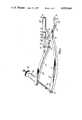
- FIG. 1is a perspective view of one form of tensioner according to the invention
- FIG. 2is a perspective view of a slightly modified form of the second extension of the tensioner shown in FIG. 1;
- FIG. 3is a perspective view of the extension shown in FIG. 2 but from the opposite side;
- FIG. 4is a cross-section through the extension shown in FIGS. 2 and 3 with the jaws apart;
- FIG. 5is a similar view to that of FIG. 4 but with the jaws closed.
- FIG. 6is a perspective view showing the screw-threaded shaft and the ends of the two handles, in a form slightly different from that of FIG. 1.
- the tensioneris made of stainless steel. It has two handles 11, 12 which are hinged together at a main hinge 13. Each handle has an extension 14, 15 respectively beyond the hinge 13.
- the first extension 14has at its end an open-ended slot 16 to receive a cable and a surface 17 to operate against the surface from which the cable protrudes.
- the second extension 15terminates in a cylinder 18, the end of which remote from the hinge 13 serves as a first jaw 19.
- a second jaw 20is attached to a shaft 21 contained within the cylinder 18 and coupled via coupling members 22, 23 and pivots 24, 25 to a short side arm provided on the handle 12.
- the handle 12is pivoted at 26 between pivot 25 and hinge 13.
- the surface against which the surface 17 operateswill be the head of a spinal screw.
- the screwwill have been secured through a spinal staple into a vertebra, and a metal cable will have been passed through a hole in the screw-head.
- Tensionis applied to the cable as described above, and then the head of the screw can be crimped over the cable so as to maintain it at the desired tension.
- the processcan be repeated with screws in subsequent vertebrae one at a time; alternatively tension can be applied over several vertebrae at once.
- a partially screw-threaded shaft 30 of rectangular cross-sectionis hinged at the end 31 of the handle 11 about hinge 32.
- This shaft 30passes through a slot in the end of the handle 12.
- a knurled nut 34is provided on the shaft and this can be screwed along the shaft to operate against a spring 35 (no visible in FIG. 1; see FIG. 6), which in turn operates against the inside of a partially dome-shaped hollow collar 36.
- This collar 36in turn operates against the handle 12 to move it in the direction 27'.
- the handles 11, 12can alternatively be moved together by manual pressure.
- FIG. 2 to 5show a slightly modified form of the extension 15 of FIG. 1.
- the extensionterminates in a cylinder 18, the end remote from the hinge 13 of which serves as a jaw 19.
- the second jaw 20is attached to a shaft 21 contained within the cylinder and this shaft 21 is attached to a coupling member 22.
- the end of the cylinder 18is bifurcated and there are two opposed slots 37, 38 each capable of receiving a lug 39 secured to the shaft 21.
- the shaft 21can be rotated within the cylinder 18 and relative to the coupling member 22, so as to align the lug 39 either with the slot 37 or with the opposed slot 38.
- the jaws 19, 20are closed, as shown in FIG.
- the lug 39is retracted into one of the slots 37, 38 (slot 38 in FIG. 5) and thus the shaft 21 is prevented from rotating.
- This rotational movement of the shaft 21permits a choice of direction for the opening between the jaws 19, 20, and thus the tensioner can be adapted for either right-hand or left-hand use.
- the jaws 19, 20are provided with respective slots 40, 41 for receiving the cable.
Landscapes
- Health & Medical Sciences (AREA)
- Surgery (AREA)
- Life Sciences & Earth Sciences (AREA)
- Biomedical Technology (AREA)
- Nuclear Medicine, Radiotherapy & Molecular Imaging (AREA)
- Engineering & Computer Science (AREA)
- Orthopedic Medicine & Surgery (AREA)
- Heart & Thoracic Surgery (AREA)
- Medical Informatics (AREA)
- Molecular Biology (AREA)
- Animal Behavior & Ethology (AREA)
- General Health & Medical Sciences (AREA)
- Public Health (AREA)
- Veterinary Medicine (AREA)
- Surgical Instruments (AREA)
Abstract
Description
This invention relates to a surgical instrument for use in the correction of curvature of the spinal column.
One technique that is used for the correction of spinal curvatures is the Dwyer technique of anterior instrumentation of the spine; (c.f. A. F. Dwyer, "Anterior approach to scoliosis," Journal of the Western Pacific Orthopaedic Association, Vol. VI, No. 1, Mar. 1969; A. F. Dwyer et al, "Anterior approach to scoliosis," Clinical Orthopaedics and Related Research, No. 62, pp. 192 - 202, 1969; and A. F. Dwyer, "Anterior approach to scoliosis," ibid, No. 93, July 1973). This technique involves operation on the front of the spine, with access to the spine being gained by the removal of one rib, or possibly of two ribs. This method may be used for the correction of scoliosis (lateral curvature of the spinal column) when posterior elements are absent, such as in myelomeningocele or after an extensive laminectomy. It is particularly useful when lordosis (curvature of the spinal column with a forward convexity) is associated with scoliosis, and can often be used as a supplementary means of fixation in very long paralytic curves, especially those associated with lordosis in the lumbar region.
The technique involves the application of compression on the convex side of the spinal curve, after the contents of the discs have been excised, so as to straighten the curve. The compression is applied by means of a metal cable threaded through the heads of screws, one of which is anchored through a metal staple in each vertebra.
A staple of "saddle" of such a size as to fit snugly over the vertebra is first selected and driven into place over the vertebra. A screw is then passed through a hole in the staple and into the vertebra until only the head of the screw protrudes above the staple. A metal cable is passed through a hole in the head of the screw. The procedure is repeated on successive vertebrae with a single cable being passed through all screw heads. Tension is applied to the cable, to obtain the necessary corrective force. The tension may be applied one stage at a time, after the cable has been passed through each respective screw-head, or it may be applied after the cable has been passed through several or all of the screw-heads. When the correct tension has been obtained, the screw-head is crimped over the cable so as to maintain the cable at the necessary tension.
The present invention relates to a surgical instrument, which is a tensioner designed specifically for applying the necessary tension to the metal cable to straighten the spinal column.
The present invention provides a surgical instrument having two handles hinged together at a main hinge, each handle having an extension beyond the hinge so arranged that movement about the hinge of the two handles toward one another causes the two extensions to move away from one another, wherein one extension has, at the end remote from the hinge, cable receiving means consisting essentially of a bifurcated arm defining a slot open at one end to receive a cable, and wherein the second extension has, at the end remote from the hinge, two jaws between which a metal cable can be gripped, the instrument having means to ensure that movement together of the two handles causes the jaws, if open, to close and movement away from one another of the two handles causes the jaws, if closed, to open prior to causing any movement of the two extensions relative to one another.
The second extension may terminate in a first member provided, at the end remote from the main hinge, with one of the jaws, and the second extension also includes a second member which is slidable with respect to the said first member and is provided, at the end remote from the main hinge, with the second jaw, wherein the said second member is coupled to the second handle, which has a pivot at a point along its length between the main hinge and the point of coupling of the said second member.
Advantageously, the axis of the pivot and the axis of the main hinge are substantially parallel. Advantageously, also, the plane in which the first jaw lies is parallel to that in which the second jaw lies irrespective of whether the jaws are open or closed. Moreover, advantageously, the said two planes are parallel to the axis of the pivot and/or parallel to the axis of the main hinge irrespective of the positions of the jaws and of the relative positions of the handles.
The second extension preferably terminates in a hollow cylinder (the said first member) the end remote from the main hinge of which serves as the first jaw, with the second jaw attached to the end of a shaft (the said second member) which is moveably contained within the cylinder and is coupled to the second handle. When the handles are moved apart, the shaft is caused to move in the direction of the end of the cylinder remote from the main hinge, thus pushing the second jaw away from the first jaw. When the handles are moved together, the shaft is pulled in the opposite direction and the jaws close. A first jaw faces in a direction away from the second handle, and the second jaw faces in the opposite direction.
Preferably, when the jaws are apart, the shaft can be rotated within the cylinder thus moving the first jaw in relation to the second jaw. This may be achieved with a number of structures known in the prior art, e.g. see U.S. Pat. Nos. 462,829; 718,306 or 3,424,027. In this way the tensioner can be adapted for either right-hand or left-hand use.
The cylinder is preferably, at the end remote from the main hinge, bifurcated, with the end surfaces of the two branches serving as the first jaw. Preferably also, a lug is secured to the shaft, which lug is accommodated in a slot between the two branches of the bifurcated cylinder, when the two jaws are closed. If the shaft can be rotated as described above, this lug can advantageously be accommodated in either slot between the two branches of the cylinder.
The end of the shaft or other second member nearer the main hinge is advantageously pivotably joined to one end of a coupling member, the other end of which is pivotably joined to the second handle or, preferably, to a short side arm provided on the second handle. Preferably, the axes of the said two pivots are parallel to one another, and preferably also parallel to the axis of the main hinge.
A screw-threaded shaft may be attached to the end of one handle and passed through the end of the other handle, with a nut, preferably a knurled nut, provided on the shaft such that it can be screwed along the shaft so as to apply pressure to push the handles together.
Various forms of tensioners according to the invention will now be described, by way of example only, with reference to the accompanying drawings, in which:
FIG. 1 is a perspective view of one form of tensioner according to the invention;
FIG. 2 is a perspective view of a slightly modified form of the second extension of the tensioner shown in FIG. 1;
FIG. 3 is a perspective view of the extension shown in FIG. 2 but from the opposite side;
FIG. 4 is a cross-section through the extension shown in FIGS. 2 and 3 with the jaws apart;
FIG. 5 is a similar view to that of FIG. 4 but with the jaws closed; and
FIG. 6 is a perspective view showing the screw-threaded shaft and the ends of the two handles, in a form slightly different from that of FIG. 1.
The tensioner is made of stainless steel. It has twohandles 11, 12 which are hinged together at a main hinge 13. Each handle has anextension first extension 14 has at its end an open-ended slot 16 to receive a cable and a surface 17 to operate against the surface from which the cable protrudes. Thesecond extension 15 terminates in acylinder 18, the end of which remote from the hinge 13 serves as afirst jaw 19. Asecond jaw 20 is attached to ashaft 21 contained within thecylinder 18 and coupled viacoupling members pivots handle 12. Thehandle 12 is pivoted at 26 betweenpivot 25 and hinge 13. When thehandles 11, 12 are moved together as shown byarrows 27, 27', thehandle 12 moves about the hinge 26 thus pulling thecoupling members shaft 21 in thedirection 28 and closing thejaws jaws handle 12 rotates relative to the handle 11 about the hinge 13 thus moving the twoextensions arrows 29, 29'. With the surface 17 abutting the surface from which a cable protrudes, and with the cable passing through theslot 16 and being gripped between thejaws handles 11, 12 together.
Normally, the surface against which the surface 17 operates will be the head of a spinal screw. The screw will have been secured through a spinal staple into a vertebra, and a metal cable will have been passed through a hole in the screw-head. Tension is applied to the cable as described above, and then the head of the screw can be crimped over the cable so as to maintain it at the desired tension. The process can be repeated with screws in subsequent vertebrae one at a time; alternatively tension can be applied over several vertebrae at once.
A partially screw-threadedshaft 30 of rectangular cross-section is hinged at theend 31 of the handle 11 abouthinge 32. Thisshaft 30 passes through a slot in the end of thehandle 12. Aknurled nut 34 is provided on the shaft and this can be screwed along the shaft to operate against a spring 35 (no visible in FIG. 1; see FIG. 6), which in turn operates against the inside of a partially dome-shapedhollow collar 36. Thiscollar 36 in turn operates against thehandle 12 to move it in the direction 27'. Thehandles 11, 12 can alternatively be moved together by manual pressure.
FIG. 2 to 5 show a slightly modified form of theextension 15 of FIG. 1. As in FIG. 1, the extension terminates in acylinder 18, the end remote from the hinge 13 of which serves as ajaw 19. Thesecond jaw 20 is attached to ashaft 21 contained within the cylinder and thisshaft 21 is attached to acoupling member 22. The end of thecylinder 18 is bifurcated and there are twoopposed slots lug 39 secured to theshaft 21. When the twojams shaft 21 can be rotated within thecylinder 18 and relative to thecoupling member 22, so as to align thelug 39 either with theslot 37 or with theopposed slot 38. When thejaws lug 39 is retracted into one of theslots 37, 38 (slot 38 in FIG. 5) and thus theshaft 21 is prevented from rotating. This rotational movement of theshaft 21 permits a choice of direction for the opening between thejaws jaws respective slots
Various surgical implants for use in the Dwyer technique of anterior instrumentation of the spine are described and claimed in the complete specifications accompanying U.K. Patent applications Nos. 17610/75, 17611/75, and 17612/75.
Claims (13)
1. A surgical instrument for applying tension to a cable for straightening a spinal column, said instrument having first and second hinged together at a main hinge, each handle having an extension beyond the hinge so arranged that movement about the hinge of the two handles toward one another causes the two extensions to move away from one another, wherein one extension has, at the end remote from the hinge, cable receiving means consisting essentially of a bifurcated arm defining a slot open at one end to receive a cable, and wherein the second extension has, at the end remote from the hinge, two jaws between which a metal cable can be gripped, the instrument having means to ensure that movement together of the two handles causes the jaws, if open, to close and movement away from one another of the two handles causes the jaws, if closed, to open prior to causing any movement of the two extensions relative to one another.
2. An instrument as claimed in claim 1, wherein the second extension terminates in a first member provided, at the end remote from the main hinge, with one of the jaws, and the second extension also includes a second member which is slidable with respect to the said first member and is provided, at the end remote from the main hinge, with the second jaw, wherein the said second member is coupled to the second handle, which has a pivot at a point along its length between the main hinge and the point of coupling of the said second member.
3. An instrument as claimed in claim 2, wherein the axis of the pivot and the axis of the main hinge are substantially parallel.
4. An instrument as claimed in claim 3, wherein the plane in which the first jaw lies is parallel to that in which the second jaw lies irrespective of whether the jaws are open or closed.
5. An instrument as claimed in claim 4, wherein the said two planes are parallel to the axis of the pivot and to the axis of the main hinge irrespective of the positions of the jaw and of the relative positions of the handles.
6. An instrument as claimed in claim 2 wherein the second extension terminates in a hollow cylinder, which constitutes the said first member, the end remote from the main hinge of which cylinder serves as the first jaw with the second jaw attached to the end of a shaft, which constitutes the said second member, moveably contained within the cylinder and coupled to the second handle.
7. An instrument as claimed in claim 6, wherein, when the jaws are apart, the shaft can be rotated within the cylinder.
8. An instrument as claimed in claim 6, wherein the cylinder is, at the end remote from the main hinge, bifurcated, with the end surfaces of the two branches of the bifurcated cylinder serving as the first jaw.
9. An instrument as claimed in claim 8, wherein a lug is secured to the shaft, which lug, when the jaws are closed, is accommodated in a slot between the two branches of the bifurcated cylinder.
10. An instrument as claimed in claim 1, wherein the proximal end of the second member nearer the main hinge is pivotably joined to one end of a coupling member, the distal end of which is pivotally joined to the second handle.
11. An instrument as claimed in claim 10, wherein the axes of the said two pivots are parallel to one another and to the axis of the main hinge.
12. An instrument as claimed claim 1, wherein a screw-threaded shaft is attached to the end of one handle and can be passed through the end of the other handle, with a nut so arranged on the shaft that it can be screwed along the shaft so as to apply pressure to push the handles together.
13. An instrument as claimed in claim 10, wherein the distal end of said coupling member is joined to the second handle via a short side arm provided on the second handle.
Applications Claiming Priority (2)
| Application Number | Priority Date | Filing Date | Title |
|---|---|---|---|
| GB17613/75AGB1551707A (en) | 1975-04-28 | 1975-04-28 | Surgical instrument |
| UK17613/75 | 1975-04-28 |
Publications (1)
| Publication Number | Publication Date |
|---|---|
| US4050464Atrue US4050464A (en) | 1977-09-27 |
Family
ID=10098207
Family Applications (1)
| Application Number | Title | Priority Date | Filing Date |
|---|---|---|---|
| US05/680,235Expired - LifetimeUS4050464A (en) | 1975-04-28 | 1976-04-26 | Surgical cable tensioning instrument |
Country Status (7)
| Country | Link |
|---|---|
| US (1) | US4050464A (en) |
| JP (1) | JPS51131193A (en) |
| AU (1) | AU500598B2 (en) |
| CA (1) | CA1069796A (en) |
| DE (1) | DE2618375A1 (en) |
| FR (1) | FR2309201A1 (en) |
| GB (1) | GB1551707A (en) |
Cited By (91)
| Publication number | Priority date | Publication date | Assignee | Title |
|---|---|---|---|---|
| US4271836A (en)* | 1976-06-28 | 1981-06-09 | Wyzsza Szkola Inzynierska Im. Jurija Gagarina | Appliance for correction of spinal curvatures |
| US4367577A (en)* | 1980-12-08 | 1983-01-11 | Muff Nicholas S | Extractor for removing broken tubing tips from catheter hubs |
| US4375161A (en)* | 1980-04-23 | 1983-03-01 | Sueddeutsche Kuehlerfabrik Julius Fr. Behr Gmbh & Co. Kg | Device for opening flanged joints |
| US4530142A (en)* | 1983-10-19 | 1985-07-23 | Schiffer John H | Tubing disconnect tool |
| US4577382A (en)* | 1984-04-18 | 1986-03-25 | Harold K. McIntire | Snap ring tool |
| US4587963A (en)* | 1983-05-26 | 1986-05-13 | Karl Leibinger | Instrument for positioning a cerclage fixation device around fractured bone parts |
| USD291729S (en) | 1985-05-08 | 1987-09-01 | Zimmer, Inc. | Spinal hook distractor or the like |
| US4712542A (en)* | 1986-06-30 | 1987-12-15 | Medmetric Corporation | System for establishing ligament graft orientation and isometry |
| US4726356A (en)* | 1985-11-12 | 1988-02-23 | Kapp Surgical Instrument, Inc. | Cardiovascular and thoracic retractor |
| FR2606312A1 (en)* | 1986-11-12 | 1988-05-13 | Peixoto Daniel | Hand instrument of the clamp type making it possible to exert successively on an object at least two separate actions developed from a single movement controlled by a user |
| US4862572A (en)* | 1988-06-02 | 1989-09-05 | Milbar Corporation | Retaining ring tool |
| US4969895A (en)* | 1989-01-23 | 1990-11-13 | Richards Medical Company | Apparatus and method for determining the tension on a ligament graft |
| US5002547A (en)* | 1987-02-07 | 1991-03-26 | Pfizer Hospital Products Group, Inc. | Apparatus for knee prosthesis |
| US5020519A (en)* | 1990-12-07 | 1991-06-04 | Zimmer, Inc. | Sagittal approximator |
| US5116340A (en)* | 1989-01-26 | 1992-05-26 | Songer Robert J | Surgical securance apparatus |
| US5122130A (en)* | 1988-03-23 | 1992-06-16 | Waldemar Link Gmbh & Co. | Forceps for inserting intervertebral device |
| US5167223A (en)* | 1989-09-08 | 1992-12-01 | Tibor Koros | Heart valve retractor and sternum spreader surgical instrument |
| US5167662A (en)* | 1992-01-24 | 1992-12-01 | Zimmer, Inc. | Temporary clamp and inserter for a posterior midline spinal clamp |
| USRE34150E (en)* | 1985-11-12 | 1992-12-29 | Kapp Surgical Instrument, Inc. | Cardiovascular and thoracic retractor |
| WO1994006362A1 (en)* | 1992-09-21 | 1994-03-31 | Ray R Charles | Tool and method for derotating scoliotic spine |
| USD346217S (en) | 1992-07-13 | 1994-04-19 | Acromed Corporation | Combined hook holder and rod mover for spinal surgery |
| US5311798A (en)* | 1990-04-02 | 1994-05-17 | Trusky Michael T | Spring spreading tool |
| US5312410A (en)* | 1992-12-07 | 1994-05-17 | Danek Medical, Inc. | Surgical cable tensioner |
| US5431659A (en)* | 1993-08-17 | 1995-07-11 | Texas Scottish Rite Hospital For Children | Pneumatic wire tensioner |
| US5449361A (en)* | 1993-04-21 | 1995-09-12 | Amei Technologies Inc. | Orthopedic cable tensioner |
| US5476465A (en)* | 1993-04-21 | 1995-12-19 | Amei Technologies Inc. | Surgical cable crimp |
| US5475941A (en)* | 1994-08-26 | 1995-12-19 | Moore; Chuck | Pork rind pliers |
| US5540698A (en)* | 1993-04-21 | 1996-07-30 | Amei Technologies Inc. | System and method for securing a medical cable |
| US5545168A (en)* | 1994-03-11 | 1996-08-13 | Burke; Dennis W. | Apparatus for both tensioning and crimping a surgical wire |
| US5846187A (en)* | 1996-09-13 | 1998-12-08 | Genzyme Corporation | Redo sternotomy retractor |
| US5891018A (en)* | 1997-09-19 | 1999-04-06 | Genzyme Corporation | Ball joint retractor |
| US6001106A (en)* | 1997-09-03 | 1999-12-14 | M & R Medical, Inc. | System for tensioning ligament grafts |
| US6146386A (en)* | 1999-02-04 | 2000-11-14 | Sdgi Holdings, Inc. | Cable operated bone anchor compressor |
| US6261296B1 (en) | 1998-10-02 | 2001-07-17 | Synthes U.S.A. | Spinal disc space distractor |
| WO2002009602A1 (en)* | 2000-07-27 | 2002-02-07 | Synthes Ag Chur | Cranial flap clamp and instrument for use therewith |
| US6368326B1 (en) | 1998-09-28 | 2002-04-09 | Daos Limited | Internal cord fixation device |
| US6383200B1 (en)* | 1999-12-21 | 2002-05-07 | Securos, Inc. | Tensioning device for cranial cruciate ligament stabilization |
| US20020120280A1 (en)* | 1999-12-21 | 2002-08-29 | Securos, Inc. | Crimping device for cranial cruciate ligament stabilization |
| US6616667B1 (en)* | 1999-11-25 | 2003-09-09 | Sulzer Orthopedics, Ltd. | Surgical instrument for tensioning a cable-like tensioning element |
| US20030229349A1 (en)* | 2002-06-11 | 2003-12-11 | Wellisz Tadeusz Z. | Cranial bone flap fixation system and method |
| US6739068B1 (en) | 2003-01-06 | 2004-05-25 | Pilling Weck Incorporated | Pliers with jaw spacing and load measuring readings |
| EP1405605A3 (en)* | 2000-07-27 | 2004-06-23 | SYNTHES AG Chur | Instrument for cranial flap clamp |
| US20040127907A1 (en)* | 1998-09-28 | 2004-07-01 | Dakin Edward B. | Internal cord fixation device |
| US20050137608A1 (en)* | 2000-07-27 | 2005-06-23 | Synthes (Usa) | Cranial flap clamp instrument |
| US20050159757A1 (en)* | 2002-06-24 | 2005-07-21 | Endius Incorporated | Surgical instrument for moving vertebrae |
| US20050192587A1 (en)* | 2004-02-27 | 2005-09-01 | Lim Roy K. | Rod reducer |
| US20050228392A1 (en)* | 2004-04-12 | 2005-10-13 | Keyer Thomas R | Rod persuader |
| US20060004380A1 (en)* | 2004-07-02 | 2006-01-05 | Didomenico Scott R | Compressor-distractor |
| US20060009775A1 (en)* | 2004-07-06 | 2006-01-12 | Brian Dec | Spinal rod insertion instrument |
| US20060025768A1 (en)* | 2003-07-03 | 2006-02-02 | Andy Iott | Top loading spinal fixation device and instruments for loading and handling the same |
| US20060089651A1 (en)* | 2004-10-26 | 2006-04-27 | Trudeau Jeffrey L | Apparatus and method for anchoring a surgical rod |
| US20060217714A1 (en)* | 2005-03-24 | 2006-09-28 | Depuy Spine, Inc. | Low profile spinal tethering methods |
| US20060235427A1 (en)* | 2005-04-14 | 2006-10-19 | Thomas Bradley G | Multi-function orthopedic instrument |
| US20070270830A1 (en)* | 2006-04-28 | 2007-11-22 | Sdgi Holdings, Inc. | Open axle surgical implant |
| US20080009863A1 (en)* | 2006-06-23 | 2008-01-10 | Zimmer Spine, Inc. | Pedicle screw distractor and associated method of use |
| US20080154277A1 (en)* | 2004-10-26 | 2008-06-26 | Scott Machalk | Tool apparatus for locking a spinal rod in an anchoring device therefor |
| US20080183191A1 (en)* | 2007-01-26 | 2008-07-31 | Hans Schoepp | Trajectory guide |
| US20080195155A1 (en)* | 2007-02-12 | 2008-08-14 | Jeffrey Hoffman | Locking instrument for implantable fixation device |
| US20080228233A1 (en)* | 2007-02-12 | 2008-09-18 | Jeffrey Hoffman | Instrument for manipulating spinal implant system |
| US20080249532A1 (en)* | 2007-04-06 | 2008-10-09 | Synthes U.S.A. | Securing device to secure fixation devices to bone portions |
| US20080287951A1 (en)* | 2007-03-22 | 2008-11-20 | Stoneburner James D | Segmented intramedullary structure |
| US20090157125A1 (en)* | 2007-02-14 | 2009-06-18 | Jeffrey Hoffman | Spinal Rod Reducer and Cap Insertion Apparatus |
| US20090228054A1 (en)* | 2008-01-29 | 2009-09-10 | Jeffrey Hoffman | Rod Locking Instrument |
| US20090259262A1 (en)* | 2008-04-15 | 2009-10-15 | Warsaw Orthopedic, Inc. | Surgical tool |
| US20100094294A1 (en)* | 2008-10-10 | 2010-04-15 | Joel Gillard | Cerclage system for bone |
| US20100319493A1 (en)* | 2009-06-17 | 2010-12-23 | Gorrie Andrew G | Jar opener and method for loosening jar lids suitable for arthritic persons |
| US20110112537A1 (en)* | 2009-10-09 | 2011-05-12 | Acute Innovations, Llc | System for tensioning a surgical wire |
| US20110202096A1 (en)* | 2010-02-12 | 2011-08-18 | John White | Spinal Rod and Screw Securing Apparatus and Method |
| US8439917B2 (en) | 2006-11-22 | 2013-05-14 | Sonoma Orthopedic Products, Inc. | Fracture fixation device, tools and methods |
| US8568413B2 (en) | 2008-12-18 | 2013-10-29 | Sonoma Orthopedic Products, Inc. | Bone fixation device, tools and methods |
| US8961516B2 (en) | 2005-05-18 | 2015-02-24 | Sonoma Orthopedic Products, Inc. | Straight intramedullary fracture fixation devices and methods |
| US8984720B2 (en) | 2011-12-28 | 2015-03-24 | Pioneer Surgical Technology, Inc. | Tensioning instrument and method |
| US9060820B2 (en) | 2005-05-18 | 2015-06-23 | Sonoma Orthopedic Products, Inc. | Segmented intramedullary fracture fixation devices and methods |
| US9155574B2 (en) | 2006-05-17 | 2015-10-13 | Sonoma Orthopedic Products, Inc. | Bone fixation device, tools and methods |
| US20150313656A1 (en)* | 2014-04-30 | 2015-11-05 | DePuy Synthes Products, Inc. | Tensioning instrument and related bone fixation systems and methods |
| US9241748B2 (en) | 2012-04-30 | 2016-01-26 | Acute Innovations Llc | System for binding bone |
| US9265543B2 (en) | 2011-12-27 | 2016-02-23 | Pioneer Surgical Technology, Inc. | Bone plate system and method |
| US9333021B2 (en) | 2012-11-21 | 2016-05-10 | Pioneer Surgical Technology, Inc. | Tensioning instrument |
| WO2017019317A1 (en)* | 2013-03-15 | 2017-02-02 | Matthew Songer | Cable fixation device, instruments, and methods |
| US9770278B2 (en) | 2014-01-17 | 2017-09-26 | Arthrex, Inc. | Dual tip guide wire |
| US9820793B1 (en)* | 2014-04-21 | 2017-11-21 | Dallen Medical, Inc. | Tensioning devices and methods for dynamic suture systems |
| CN109561967A (en)* | 2016-08-02 | 2019-04-02 | 黑普创新技术有限责任公司 | For separating the tool and method of femoral cup or femoral ball from femoral implant |
| US10314635B2 (en) | 2014-05-28 | 2019-06-11 | A&E Advanced Closure Systems, Llc | Tensioning instruments |
| US10426459B2 (en) | 2016-07-05 | 2019-10-01 | Mortise Medical, LLC | Extra joint stabilization construct |
| US10463410B2 (en) | 2016-01-22 | 2019-11-05 | A&E Advanced Closure Systems, Llc | Bone plate having a connector and a connector for a surgical loop |
| US10485600B2 (en) | 2016-07-29 | 2019-11-26 | A&E Advanced Closure Systems, Llc | Surgical cable tensioner |
| US10765465B2 (en) | 2012-11-21 | 2020-09-08 | A&E Advanced Closure Systems, Llc | Tensioning instrument |
| US10881437B2 (en) | 2013-12-05 | 2021-01-05 | A&E Advanced Closure Systems, Llc | Bone plate system and method |
| US11083510B1 (en) | 2021-04-19 | 2021-08-10 | Giftedness And Creativity Company | Surgical wire twisting tool |
| US20230100706A1 (en)* | 2020-10-07 | 2023-03-30 | Globus Medical, Inc. | Tensioning instruments |
| US20240024008A1 (en)* | 2022-07-19 | 2024-01-25 | Brent Lane Norris | Fracture distractor pliers |
Families Citing this family (5)
| Publication number | Priority date | Publication date | Assignee | Title |
|---|---|---|---|---|
| USRE36221E (en)* | 1989-02-03 | 1999-06-01 | Breard; Francis Henri | Flexible inter-vertebral stabilizer as well as process and apparatus for determining or verifying its tension before installation on the spinal column |
| FR2642645B1 (en)* | 1989-02-03 | 1992-08-14 | Breard Francis | FLEXIBLE INTERVERTEBRAL STABILIZER AND METHOD AND APPARATUS FOR CONTROLLING ITS VOLTAGE BEFORE PLACEMENT ON THE RACHIS |
| US6022377A (en)* | 1998-01-20 | 2000-02-08 | Sulzer Orthopedics Inc. | Instrument for evaluating balance of knee joint |
| FR2777449B1 (en)* | 1998-04-17 | 2000-09-15 | Sulzer Orthopedics Limited | TENSIONING DEVICE FOR LAYING A SPINAL STABILIZATION SYSTEM |
| EP1103225B1 (en) | 1999-11-25 | 2004-09-15 | Centerpulse Orthopedics Ltd. | Surgical instrument for tensioning a cable-like tension element |
Citations (1)
| Publication number | Priority date | Publication date | Assignee | Title |
|---|---|---|---|---|
| US2291413A (en)* | 1941-06-13 | 1942-07-28 | John R Siebrandt | Bone clamping and wire adjusting means |
Family Cites Families (2)
| Publication number | Priority date | Publication date | Assignee | Title |
|---|---|---|---|---|
| CH303821A (en)* | 1952-07-25 | 1954-12-15 | Roland Dr Med Leemann | Tensioning instrument. |
| DE1007705B (en)* | 1955-03-14 | 1957-05-02 | Dr Med Eberhard Zohlen | Spreader pliers for twisting wire ends, especially for wire ligatures in the case of bone fractures |
- 1975
- 1975-04-28GBGB17613/75Apatent/GB1551707A/ennot_activeExpired
- 1976
- 1976-04-23CACA250,885Apatent/CA1069796A/ennot_activeExpired
- 1976-04-26USUS05/680,235patent/US4050464A/ennot_activeExpired - Lifetime
- 1976-04-27DEDE19762618375patent/DE2618375A1/ennot_activeWithdrawn
- 1976-04-28AUAU13448/76Apatent/AU500598B2/ennot_activeExpired
- 1976-04-28FRFR7612567Apatent/FR2309201A1/enactivePending
- 1976-04-28JPJP51049344Apatent/JPS51131193A/enactivePending
Patent Citations (1)
| Publication number | Priority date | Publication date | Assignee | Title |
|---|---|---|---|---|
| US2291413A (en)* | 1941-06-13 | 1942-07-28 | John R Siebrandt | Bone clamping and wire adjusting means |
Non-Patent Citations (2)
| Title |
|---|
| "Harris' Wire Knot Tightener" (G520), Orthopaedic Catalogue, Down Bros. & Mayer & Phelps Ltd, p. G67.* |
| "Harris Wire Knot Tightener" Advertisement, p. 66, Downs Surgical, Inc., The Journal of Bone & Joint Surgery, vol. 50-A, No. 3, Apr. 1968.* |
Cited By (158)
| Publication number | Priority date | Publication date | Assignee | Title |
|---|---|---|---|---|
| US4271836A (en)* | 1976-06-28 | 1981-06-09 | Wyzsza Szkola Inzynierska Im. Jurija Gagarina | Appliance for correction of spinal curvatures |
| US4375161A (en)* | 1980-04-23 | 1983-03-01 | Sueddeutsche Kuehlerfabrik Julius Fr. Behr Gmbh & Co. Kg | Device for opening flanged joints |
| US4367577A (en)* | 1980-12-08 | 1983-01-11 | Muff Nicholas S | Extractor for removing broken tubing tips from catheter hubs |
| US4587963A (en)* | 1983-05-26 | 1986-05-13 | Karl Leibinger | Instrument for positioning a cerclage fixation device around fractured bone parts |
| US4530142A (en)* | 1983-10-19 | 1985-07-23 | Schiffer John H | Tubing disconnect tool |
| US4577382A (en)* | 1984-04-18 | 1986-03-25 | Harold K. McIntire | Snap ring tool |
| USD291729S (en) | 1985-05-08 | 1987-09-01 | Zimmer, Inc. | Spinal hook distractor or the like |
| USRE34150E (en)* | 1985-11-12 | 1992-12-29 | Kapp Surgical Instrument, Inc. | Cardiovascular and thoracic retractor |
| US4726356A (en)* | 1985-11-12 | 1988-02-23 | Kapp Surgical Instrument, Inc. | Cardiovascular and thoracic retractor |
| US4712542A (en)* | 1986-06-30 | 1987-12-15 | Medmetric Corporation | System for establishing ligament graft orientation and isometry |
| FR2606312A1 (en)* | 1986-11-12 | 1988-05-13 | Peixoto Daniel | Hand instrument of the clamp type making it possible to exert successively on an object at least two separate actions developed from a single movement controlled by a user |
| US5002547A (en)* | 1987-02-07 | 1991-03-26 | Pfizer Hospital Products Group, Inc. | Apparatus for knee prosthesis |
| US5122130A (en)* | 1988-03-23 | 1992-06-16 | Waldemar Link Gmbh & Co. | Forceps for inserting intervertebral device |
| US4862572A (en)* | 1988-06-02 | 1989-09-05 | Milbar Corporation | Retaining ring tool |
| US4969895A (en)* | 1989-01-23 | 1990-11-13 | Richards Medical Company | Apparatus and method for determining the tension on a ligament graft |
| US5116340A (en)* | 1989-01-26 | 1992-05-26 | Songer Robert J | Surgical securance apparatus |
| US5167223A (en)* | 1989-09-08 | 1992-12-01 | Tibor Koros | Heart valve retractor and sternum spreader surgical instrument |
| US5311798A (en)* | 1990-04-02 | 1994-05-17 | Trusky Michael T | Spring spreading tool |
| US5020519A (en)* | 1990-12-07 | 1991-06-04 | Zimmer, Inc. | Sagittal approximator |
| US5167662A (en)* | 1992-01-24 | 1992-12-01 | Zimmer, Inc. | Temporary clamp and inserter for a posterior midline spinal clamp |
| USD346217S (en) | 1992-07-13 | 1994-04-19 | Acromed Corporation | Combined hook holder and rod mover for spinal surgery |
| TR28257A (en)* | 1992-09-21 | 1996-03-20 | Charles Ray R | Tool and method to prevent the scolitic spine from rotating. |
| WO1994006362A1 (en)* | 1992-09-21 | 1994-03-31 | Ray R Charles | Tool and method for derotating scoliotic spine |
| US5312410A (en)* | 1992-12-07 | 1994-05-17 | Danek Medical, Inc. | Surgical cable tensioner |
| US5476465A (en)* | 1993-04-21 | 1995-12-19 | Amei Technologies Inc. | Surgical cable crimp |
| US5449361A (en)* | 1993-04-21 | 1995-09-12 | Amei Technologies Inc. | Orthopedic cable tensioner |
| US5540698A (en)* | 1993-04-21 | 1996-07-30 | Amei Technologies Inc. | System and method for securing a medical cable |
| US5431659A (en)* | 1993-08-17 | 1995-07-11 | Texas Scottish Rite Hospital For Children | Pneumatic wire tensioner |
| US5545168A (en)* | 1994-03-11 | 1996-08-13 | Burke; Dennis W. | Apparatus for both tensioning and crimping a surgical wire |
| US5868748A (en)* | 1994-03-11 | 1999-02-09 | Burke; Dennis W. | Apparatus for both tensioning and crimping a surgical wire |
| US5475941A (en)* | 1994-08-26 | 1995-12-19 | Moore; Chuck | Pork rind pliers |
| US5846187A (en)* | 1996-09-13 | 1998-12-08 | Genzyme Corporation | Redo sternotomy retractor |
| US5846191A (en)* | 1996-09-13 | 1998-12-08 | Genzyme Corporation | Redo sternotomy retractor |
| US6001106A (en)* | 1997-09-03 | 1999-12-14 | M & R Medical, Inc. | System for tensioning ligament grafts |
| US5891018A (en)* | 1997-09-19 | 1999-04-06 | Genzyme Corporation | Ball joint retractor |
| US5904650A (en)* | 1997-09-19 | 1999-05-18 | Genzyme Corporation | Ball joint retractor |
| US6368326B1 (en) | 1998-09-28 | 2002-04-09 | Daos Limited | Internal cord fixation device |
| US7410489B2 (en) | 1998-09-28 | 2008-08-12 | Daos Limited | Internal cord fixation device |
| US20040127907A1 (en)* | 1998-09-28 | 2004-07-01 | Dakin Edward B. | Internal cord fixation device |
| US6712825B2 (en) | 1998-10-02 | 2004-03-30 | Max Aebi | Spinal disc space distractor |
| US20050177173A1 (en)* | 1998-10-02 | 2005-08-11 | Max Aebi | Spinal disc space distractor |
| US6261296B1 (en) | 1998-10-02 | 2001-07-17 | Synthes U.S.A. | Spinal disc space distractor |
| US6146386A (en)* | 1999-02-04 | 2000-11-14 | Sdgi Holdings, Inc. | Cable operated bone anchor compressor |
| US6616667B1 (en)* | 1999-11-25 | 2003-09-09 | Sulzer Orthopedics, Ltd. | Surgical instrument for tensioning a cable-like tensioning element |
| US20090248063A1 (en)* | 1999-12-21 | 2009-10-01 | Wotton Iii Harry | Crimping device for cranial cruciate ligament stabilization |
| US20020120280A1 (en)* | 1999-12-21 | 2002-08-29 | Securos, Inc. | Crimping device for cranial cruciate ligament stabilization |
| US6383200B1 (en)* | 1999-12-21 | 2002-05-07 | Securos, Inc. | Tensioning device for cranial cruciate ligament stabilization |
| US7993349B2 (en) | 2000-07-27 | 2011-08-09 | Synthes Usa, Llc | Cranial flap clamp instrument |
| EP1405605A3 (en)* | 2000-07-27 | 2004-06-23 | SYNTHES AG Chur | Instrument for cranial flap clamp |
| US20050137608A1 (en)* | 2000-07-27 | 2005-06-23 | Synthes (Usa) | Cranial flap clamp instrument |
| WO2002009602A1 (en)* | 2000-07-27 | 2002-02-07 | Synthes Ag Chur | Cranial flap clamp and instrument for use therewith |
| US7361178B2 (en) | 2000-07-27 | 2008-04-22 | Synthes (U.S.A.) | Cranial flap clamp and instrument for use therewith |
| US20030229349A1 (en)* | 2002-06-11 | 2003-12-11 | Wellisz Tadeusz Z. | Cranial bone flap fixation system and method |
| US7048737B2 (en)* | 2002-06-11 | 2006-05-23 | Bioplate, Inc. | Cranial bone flap fixation system and method |
| US20050159757A1 (en)* | 2002-06-24 | 2005-07-21 | Endius Incorporated | Surgical instrument for moving vertebrae |
| US7988700B2 (en) | 2002-06-24 | 2011-08-02 | Zimmer Spine, Inc. | Surgical instrument for moving vertebrae |
| US7815650B2 (en) | 2002-06-24 | 2010-10-19 | Zimmer Spine, Inc. | Surgical instrument for moving vertebrae |
| US7713274B2 (en)* | 2002-06-24 | 2010-05-11 | Zimmer Spine, Inc. | Surgical instrument for moving vertebrae |
| US20080221627A1 (en)* | 2002-06-24 | 2008-09-11 | Shluzas Alan E | Surgical instrument for moving vertebrae |
| US6739068B1 (en) | 2003-01-06 | 2004-05-25 | Pilling Weck Incorporated | Pliers with jaw spacing and load measuring readings |
| US20060025768A1 (en)* | 2003-07-03 | 2006-02-02 | Andy Iott | Top loading spinal fixation device and instruments for loading and handling the same |
| US7922724B2 (en) | 2004-02-27 | 2011-04-12 | Warsaw Orthopedic, Inc. | Rod reducer |
| US7611517B2 (en) | 2004-02-27 | 2009-11-03 | Warsaw Orthopedic, Inc. | Rod reducer |
| US20060276798A1 (en)* | 2004-02-27 | 2006-12-07 | Sdgi Holdings, Inc. | Rod reducer |
| US20050192587A1 (en)* | 2004-02-27 | 2005-09-01 | Lim Roy K. | Rod reducer |
| US20050228392A1 (en)* | 2004-04-12 | 2005-10-13 | Keyer Thomas R | Rod persuader |
| US7491207B2 (en) | 2004-04-12 | 2009-02-17 | Synthes Usa, Llc | Rod persuader |
| US20060004380A1 (en)* | 2004-07-02 | 2006-01-05 | Didomenico Scott R | Compressor-distractor |
| US9351773B2 (en) | 2004-07-02 | 2016-05-31 | DePuy Synthes Products, Inc. | Compressor-distractor |
| US8753348B2 (en) | 2004-07-02 | 2014-06-17 | DePuy Synthes Products, LLC | Compressor-distractor |
| US7371239B2 (en) | 2004-07-06 | 2008-05-13 | Synthes (U.S.A.) | Spinal rod insertion instrument |
| US20060009775A1 (en)* | 2004-07-06 | 2006-01-12 | Brian Dec | Spinal rod insertion instrument |
| US20060089651A1 (en)* | 2004-10-26 | 2006-04-27 | Trudeau Jeffrey L | Apparatus and method for anchoring a surgical rod |
| US20080154277A1 (en)* | 2004-10-26 | 2008-06-26 | Scott Machalk | Tool apparatus for locking a spinal rod in an anchoring device therefor |
| US20060217713A1 (en)* | 2005-03-24 | 2006-09-28 | Serhan Hassan A | Low profile spinal tethering devices |
| US20060217715A1 (en)* | 2005-03-24 | 2006-09-28 | Depuy Spine, Inc. | Low profile spinal tethering systems |
| US8273086B2 (en) | 2005-03-24 | 2012-09-25 | Depuy Spine, Inc. | Low profile spinal tethering devices |
| US8123749B2 (en) | 2005-03-24 | 2012-02-28 | Depuy Spine, Inc. | Low profile spinal tethering systems |
| US10194954B2 (en) | 2005-03-24 | 2019-02-05 | DePuy Synthes Products, Inc. | Low profile spinal tethering devices |
| US8888818B2 (en) | 2005-03-24 | 2014-11-18 | DePuy Synthes Products, LLC | Low profile spinal tethering methods |
| US9492165B2 (en) | 2005-03-24 | 2016-11-15 | DePuy Synthes Products, Inc. | Low profile spinal tethering devices |
| US11103288B2 (en) | 2005-03-24 | 2021-08-31 | DePuy Synthes Products, Inc. | Low profile spinal tethering devices |
| US12262924B2 (en) | 2005-03-24 | 2025-04-01 | DePuy Synthes Products, Inc. | Low profile spinal tethering devices |
| US20100106195A1 (en)* | 2005-03-24 | 2010-04-29 | Depuy Spine, Inc. | Low profile spinal tethering methods |
| US20060217714A1 (en)* | 2005-03-24 | 2006-09-28 | Depuy Spine, Inc. | Low profile spinal tethering methods |
| US7909826B2 (en) | 2005-03-24 | 2011-03-22 | Depuy Spine, Inc. | Low profile spinal tethering methods |
| US20060235427A1 (en)* | 2005-04-14 | 2006-10-19 | Thomas Bradley G | Multi-function orthopedic instrument |
| US8668699B2 (en)* | 2005-04-14 | 2014-03-11 | Warsaw Orthopedic, Inc. | Multi-function orthopedic instrument |
| WO2007027209A1 (en)* | 2005-04-14 | 2007-03-08 | Warsaw Orthopedic, Inc. | Multi-function orthopedic instrument |
| US9060820B2 (en) | 2005-05-18 | 2015-06-23 | Sonoma Orthopedic Products, Inc. | Segmented intramedullary fracture fixation devices and methods |
| US8961516B2 (en) | 2005-05-18 | 2015-02-24 | Sonoma Orthopedic Products, Inc. | Straight intramedullary fracture fixation devices and methods |
| US20070270830A1 (en)* | 2006-04-28 | 2007-11-22 | Sdgi Holdings, Inc. | Open axle surgical implant |
| US7731735B2 (en) | 2006-04-28 | 2010-06-08 | Warsaw Orthopedic, Inc. | Open axle surgical implant |
| US8025683B2 (en) | 2006-04-28 | 2011-09-27 | Warsaw Orthopedic, Inc. | Open axle surgical implant |
| US9155574B2 (en) | 2006-05-17 | 2015-10-13 | Sonoma Orthopedic Products, Inc. | Bone fixation device, tools and methods |
| US20080009863A1 (en)* | 2006-06-23 | 2008-01-10 | Zimmer Spine, Inc. | Pedicle screw distractor and associated method of use |
| US8439917B2 (en) | 2006-11-22 | 2013-05-14 | Sonoma Orthopedic Products, Inc. | Fracture fixation device, tools and methods |
| US7736371B2 (en)* | 2007-01-26 | 2010-06-15 | Stryker Leibinger Gmbh & Co. Kg | Trajectory guide |
| US20080183191A1 (en)* | 2007-01-26 | 2008-07-31 | Hans Schoepp | Trajectory guide |
| US20080228233A1 (en)* | 2007-02-12 | 2008-09-18 | Jeffrey Hoffman | Instrument for manipulating spinal implant system |
| US20080195155A1 (en)* | 2007-02-12 | 2008-08-14 | Jeffrey Hoffman | Locking instrument for implantable fixation device |
| US20090157125A1 (en)* | 2007-02-14 | 2009-06-18 | Jeffrey Hoffman | Spinal Rod Reducer and Cap Insertion Apparatus |
| US8308774B2 (en) | 2007-02-14 | 2012-11-13 | Pioneer Surgical Technology, Inc. | Spinal rod reducer and cap insertion apparatus |
| US8430879B2 (en)* | 2007-03-22 | 2013-04-30 | Sonoma Orthopedic Products, Inc. | Segmented intramedullary structure |
| US8496658B2 (en) | 2007-03-22 | 2013-07-30 | Sonoma Orthopedic Products, Inc. | Segmented intramedullary structure |
| US20080287951A1 (en)* | 2007-03-22 | 2008-11-20 | Stoneburner James D | Segmented intramedullary structure |
| US20080249532A1 (en)* | 2007-04-06 | 2008-10-09 | Synthes U.S.A. | Securing device to secure fixation devices to bone portions |
| US8500739B2 (en) | 2007-04-06 | 2013-08-06 | DePuy Synthes Products, LLC | Securing device to secure fixation devices to bone portions |
| US9351765B2 (en) | 2007-04-06 | 2016-05-31 | DePuy Synthes Products, Inc. | Securing device to secure fixation devices to bone portions |
| US8235997B2 (en) | 2008-01-29 | 2012-08-07 | Pioneer Surgical Technology, Inc. | Rod locking instrument |
| US20090228054A1 (en)* | 2008-01-29 | 2009-09-10 | Jeffrey Hoffman | Rod Locking Instrument |
| US20090259262A1 (en)* | 2008-04-15 | 2009-10-15 | Warsaw Orthopedic, Inc. | Surgical tool |
| US8486114B2 (en) | 2008-10-10 | 2013-07-16 | Acute Innovations Llc | Cerclage system for bone |
| US20100094294A1 (en)* | 2008-10-10 | 2010-04-15 | Joel Gillard | Cerclage system for bone |
| US9237913B2 (en) | 2008-10-10 | 2016-01-19 | Acute Innovations Llc | Cerclage system for bone |
| US8568413B2 (en) | 2008-12-18 | 2013-10-29 | Sonoma Orthopedic Products, Inc. | Bone fixation device, tools and methods |
| US8001872B2 (en)* | 2009-06-17 | 2011-08-23 | Gorrie Andrew G | Jar opener and method for loosening jar lids suitable for arthritic persons |
| US20100319493A1 (en)* | 2009-06-17 | 2010-12-23 | Gorrie Andrew G | Jar opener and method for loosening jar lids suitable for arthritic persons |
| US20110112537A1 (en)* | 2009-10-09 | 2011-05-12 | Acute Innovations, Llc | System for tensioning a surgical wire |
| US8679122B2 (en) | 2009-10-09 | 2014-03-25 | Acute Innovations Llc | System for tensioning a surgical wire |
| US20110202096A1 (en)* | 2010-02-12 | 2011-08-18 | John White | Spinal Rod and Screw Securing Apparatus and Method |
| US8900240B2 (en) | 2010-02-12 | 2014-12-02 | Pioneer Surgical Technology, Inc. | Spinal rod and screw securing apparatus and method |
| US9265543B2 (en) | 2011-12-27 | 2016-02-23 | Pioneer Surgical Technology, Inc. | Bone plate system and method |
| US8984720B2 (en) | 2011-12-28 | 2015-03-24 | Pioneer Surgical Technology, Inc. | Tensioning instrument and method |
| US9241748B2 (en) | 2012-04-30 | 2016-01-26 | Acute Innovations Llc | System for binding bone |
| US9421050B2 (en) | 2012-04-30 | 2016-08-23 | Acute Innovations Llc | System for binding bone |
| US9333021B2 (en) | 2012-11-21 | 2016-05-10 | Pioneer Surgical Technology, Inc. | Tensioning instrument |
| US9561064B2 (en) | 2012-11-21 | 2017-02-07 | Pioneer Surgical Technology, Inc. | Bone plate system and method |
| US10765465B2 (en) | 2012-11-21 | 2020-09-08 | A&E Advanced Closure Systems, Llc | Tensioning instrument |
| US10426532B2 (en) | 2012-11-21 | 2019-10-01 | A&E Advanced Closure Systems, Llc | Bone plate system and method |
| WO2017019317A1 (en)* | 2013-03-15 | 2017-02-02 | Matthew Songer | Cable fixation device, instruments, and methods |
| US10881437B2 (en) | 2013-12-05 | 2021-01-05 | A&E Advanced Closure Systems, Llc | Bone plate system and method |
| US9770278B2 (en) | 2014-01-17 | 2017-09-26 | Arthrex, Inc. | Dual tip guide wire |
| US9820793B1 (en)* | 2014-04-21 | 2017-11-21 | Dallen Medical, Inc. | Tensioning devices and methods for dynamic suture systems |
| US10568676B2 (en) | 2014-04-21 | 2020-02-25 | Zimmer, Inc. | Tensioning devices and methods for dynamic suture systems |
| US10052143B2 (en)* | 2014-04-30 | 2018-08-21 | DePuy Synthes Products, Inc. | Tensioning instrument and related bone fixation systems and methods |
| US20150313656A1 (en)* | 2014-04-30 | 2015-11-05 | DePuy Synthes Products, Inc. | Tensioning instrument and related bone fixation systems and methods |
| US10314635B2 (en) | 2014-05-28 | 2019-06-11 | A&E Advanced Closure Systems, Llc | Tensioning instruments |
| US11298172B2 (en) | 2014-05-28 | 2022-04-12 | A&E Advanced Closure Systems, Llc | Tensioning instruments |
| US11413077B2 (en) | 2016-01-22 | 2022-08-16 | A&E Advanced Closure Systems, Llc | Bone plate having a connector and a connector for a surgical loop |
| US10463410B2 (en) | 2016-01-22 | 2019-11-05 | A&E Advanced Closure Systems, Llc | Bone plate having a connector and a connector for a surgical loop |
| US10842480B2 (en) | 2016-07-05 | 2020-11-24 | Crossroads Extremity Systems, Llc | Multiple suture threader and methods of use |
| US10682131B2 (en) | 2016-07-05 | 2020-06-16 | Crossroads Extremity Systems, Llc | Intra joint stabilization construct |
| US12357295B2 (en) | 2016-07-05 | 2025-07-15 | Crossroads Extremity Systems, Llc | Compression and tension instruments and methods of use to reinforce ligaments |
| US11234688B2 (en) | 2016-07-05 | 2022-02-01 | Crossroads Extremity Systems, Llc | Compression and tension instruments and methods of use to reinforce ligaments |
| US11241225B2 (en) | 2016-07-05 | 2022-02-08 | Crossroads Extremity Systems, Llc | Extra joint stabilization construct |
| US10426460B2 (en) | 2016-07-05 | 2019-10-01 | Mortise Medical, LLC | Compression and tension instruments and methods of use to reinforce ligaments |
| US10426459B2 (en) | 2016-07-05 | 2019-10-01 | Mortise Medical, LLC | Extra joint stabilization construct |
| US12343002B2 (en) | 2016-07-05 | 2025-07-01 | Crossroads Extremity Systems, Llc | Extra joint stabilization construct |
| US11937801B2 (en) | 2016-07-05 | 2024-03-26 | Crossroads Extremity Systems, Llc | Intra joint stabilization construct |
| US12042138B2 (en) | 2016-07-05 | 2024-07-23 | Crossroads Extremity Systems, Llc | Multiple suture threader and methods of use |
| US10485600B2 (en) | 2016-07-29 | 2019-11-26 | A&E Advanced Closure Systems, Llc | Surgical cable tensioner |
| KR20190114949A (en)* | 2016-08-02 | 2019-10-10 | 힙 이노베이션 테크놀러지 엘엘씨 | Tools and methods for separating femoral cups or femoral balls from femoral implants |
| CN109561967A (en)* | 2016-08-02 | 2019-04-02 | 黑普创新技术有限责任公司 | For separating the tool and method of femoral cup or femoral ball from femoral implant |
| US20230100706A1 (en)* | 2020-10-07 | 2023-03-30 | Globus Medical, Inc. | Tensioning instruments |
| US12303179B2 (en)* | 2020-10-07 | 2025-05-20 | Globus Medical, Inc. | Tensioning instruments |
| US11083510B1 (en) | 2021-04-19 | 2021-08-10 | Giftedness And Creativity Company | Surgical wire twisting tool |
| US20240024008A1 (en)* | 2022-07-19 | 2024-01-25 | Brent Lane Norris | Fracture distractor pliers |
Also Published As
| Publication number | Publication date |
|---|---|
| CA1069796A (en) | 1980-01-15 |
| GB1551707A (en) | 1979-08-30 |
| DE2618375A1 (en) | 1976-11-11 |
| FR2309201A1 (en) | 1976-11-26 |
| JPS51131193A (en) | 1976-11-15 |
| AU1344876A (en) | 1977-11-03 |
| AU500598B2 (en) | 1979-05-24 |
Similar Documents
| Publication | Publication Date | Title |
|---|---|---|
| US4050464A (en) | Surgical cable tensioning instrument | |
| US8753348B2 (en) | Compressor-distractor | |
| US11903621B2 (en) | Rod reduction device and method of use | |
| US7008432B2 (en) | Device for distracting or compressing bones on bone fragments | |
| US7326218B2 (en) | Bone plate and retractor assembly | |
| US9949778B2 (en) | Spinal implant with flexible tie | |
| US5392789A (en) | Endoscopic scissors having scissor elements loosely engaged with a clevis | |
| US6015409A (en) | Apparatus and method for spinal fixation and correction of spinal deformities | |
| US5565004A (en) | Christoudias twin forceps approximator | |
| US5964769A (en) | Surgical cable system and method | |
| EP0719118B1 (en) | Apparatus for spinal fixation | |
| US8915925B2 (en) | Percutaneous compression and distraction system | |
| US6015413A (en) | Device for the extraction of screw-threaded wires particularly for orthopaedic surgical operations | |
| US8562681B2 (en) | Laminoplasty implant, method and instrumentation | |
| EP3517063B1 (en) | Compression/distraction device for use in spinal surgery | |
| US20070270869A1 (en) | Surgical instrumentation for rod reduction | |
| US20090259262A1 (en) | Surgical tool | |
| US20120197304A1 (en) | Expansion and compression instrument for fracture fixation | |
| US10441337B2 (en) | Distraction and compression in one plier | |
| US20090012539A1 (en) | Surgical clamping instruments and methods | |
| US4869243A (en) | Device and method for joining fractured bones | |
| AU743254B2 (en) | Surgical cable system and method | |
| US20240041502A1 (en) | Spinal rod coupler and system for spinal corrective surgery | |
| WO2017020152A1 (en) | Bender | |
| JP2002306499A (en) | Medical hand tool |