US4038991A - Cardiac pacer with rate limiting means - Google Patents
Cardiac pacer with rate limiting meansDownload PDFInfo
- Publication number
- US4038991A US4038991AUS05/666,737US66673776AUS4038991AUS 4038991 AUS4038991 AUS 4038991AUS 66673776 AUS66673776 AUS 66673776AUS 4038991 AUS4038991 AUS 4038991A
- Authority
- US
- United States
- Prior art keywords
- output
- gate
- counter
- stimulation pulse
- input
- Prior art date
- Legal status (The legal status is an assumption and is not a legal conclusion. Google has not performed a legal analysis and makes no representation as to the accuracy of the status listed.)
- Expired - Lifetime
Links
Images
Classifications
- A—HUMAN NECESSITIES
- A61—MEDICAL OR VETERINARY SCIENCE; HYGIENE
- A61N—ELECTROTHERAPY; MAGNETOTHERAPY; RADIATION THERAPY; ULTRASOUND THERAPY
- A61N1/00—Electrotherapy; Circuits therefor
- A61N1/18—Applying electric currents by contact electrodes
- A61N1/32—Applying electric currents by contact electrodes alternating or intermittent currents
- A61N1/36—Applying electric currents by contact electrodes alternating or intermittent currents for stimulation
- A61N1/362—Heart stimulators
- A61N1/365—Heart stimulators controlled by a physiological parameter, e.g. heart potential
Definitions
- This inventionrelates to cardiac pacers, and more particularly, to cardiac pacers employing digital circuitry means for controlling the pacer operation.
- Digital cardiac pacershave been described, most of which are intended for implantation into the body of the patient.
- a pacerwhich can be employed externally to the patient, which can selectively provide an indication of its proper operation, which provides a circuit to prevent runaway of the pacer due to component drifts, and which is efficient in its power consumption requirements.
- the inventionin its broad aspect, presents a cardiac demand pacer for producing stimulation pulses for delivery to electrodes adapted to be connected to a heart to be stimulated.
- the pacerincludes means connected to the electrodes for producing a signal indicating the presence of a heartbeat.
- An oscillatoris provided for producing periodic pulses, and first and second pulse counter means are connected to the oscillator.
- the first pulse counter meanscounts a refractory period and the second pulse counter means counts a stimulation period.
- the first pulse counter meansis reset by a heartbeat indicating signal, and produces a resetting signal upon being reset by the heartbeat indicating signal after the refractory period count to reset the second counter means.
- a stimulation pulse generatoris also provided which is activated by the second counter means upon reaching the stimulation pulse period to deliver a stimulation pulse to the electrodes.
- rate limiting meansare provided to prevent the pacer from producing a stimulation pulse in the event the stimulation pulse rate exceeds a predetermined rate.
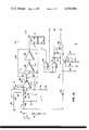
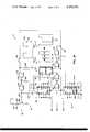
- FIGS. 1A and 1Bshow an electrical schematic diagram of an external heart pacer in accordance with a preferred embodiment of the invention.
- the external cardiac pacer of the inventionis shown in FIGS. 1A and 1B, and is illustrated by the general reference numeral 10.
- the pacerincludes six general circuits: an R-wave detector and amplifier circuit 11, a refractory period timer 12, a stimulation pulse interval timer 13, an output pulse amplifier 14, a rate limiting circuit 15 and a test circuit 16 for indicating the production of a stimulation pulse.
- the paceris designed for connection to electrodes (not shown) adapted to be connected to the user's heart, such electrodes, being known in the art, are not described herein in further detail. Terminals 17 are provided for such electrode connection. Thus, the cardiac pulses produced by the pacer 10 are conducted upon a line 18, connected to the terminal 17.
- a stimulation pulse timing circuit 13For the purpose of generating the stimulation pulses, a stimulation pulse timing circuit 13 is used.
- the timing circuit 13includes a master oscillator circuit 22, which includes an astable multivibrator 23, the oscillation rate of which is controlled by a capacitor 24, a variable resistor 25, and a fixed resistor 26.
- the capacitor 24is connected between the C and R-C inputs to the astable multivibrator 23, and the fixed resistor 26 and variable resistor 25 are connected in series between the R-C and R inputs.
- the output from the astable multivibrator 23is taken from the Q output terminal thereof.
- a counter 27counts the pulses produced at the Q output of the astable multivibrator 23.
- the Q output of the astable multivibrator 23is connected to the ⁇ I input of the counter 27, and the output of the counter 27 is derived at its Q 9 output terminal.
- the manner of operation of the counter 27is that it is advanced one step in binary order on the negative transition of ⁇ I .
- the output state upon the output terminal Q 9is controlled by the selection of the values of the capacitor 24 and resistors 25 and 26.
- the output upon the terminal Q 9 of the counter 27is conducted to a "one shot" multivibrator circuit 28 which includes two NOR gates 29 and 30.
- the output of the NOR gate 29is connected to the input terminals of the NOR gate 30 by a capacitor 32 and the output of the NOR gate 30 is connected to an input of the NOR gate 29 to provide a feedback path.
- the output terminal Q 9 of the counter 27is connected to the other input of the NOR gate 29.
- resistors 35-38are connected between the inputs of the NOR gate 30 and terminals of a switch 40 which is connected to ground.
- the pulse width of the pulse produced at the output of the NOR gate 30can be controlled by the selection of one of the resistors 35-38 by the switch 40. This selection capability provides a pulse width adjustment, as will be described below in detail.
- the output of the NOR gate 30is connected to the reset terminal of the counter 27 via a NOR gate 43 and an inverter connected NOR gate 44.
- the output from the NOR gate 30changes from low to high states, thereby resetting the count of the counter 27.
- the period of the change in state on the output terminal Q 9therefore, corresponds to the asynchronous rate of the cardiac pacer 10.
- the output of the NOR gate 30is also conducted to the stimulation pulse amplifier 14 to produce a stimulation pulse for delivery upon line 18 to the heart electrodes at terminal 17, as presently described.
- the stimulation pulse amplifier 14includes two transistors 50 and 51.
- the emitter of the transistor 50is connected to a negative terminal, and the collector is connected to the emitter of the transistor 51.
- a resistor 55is connected between the output of the NOR gate 30 and the base of the transistor 50 to conduct the output pulse produced by the NOR gate 30 thereto to control the conduction thereof.
- the collector of the transistor 51is connected by a capacitor 60 to the output line 18.
- a variable resistor 53is connected in series with a fixed resistor 54, the series being connected between the base of the transistor 51 and ground. The wiper arm of the variable resistor 53 is connected to the topside of the fixed resistor 54.
- a resistor 56is connected from the base of the transistor 51 to a negative terminal, as shown, to bias the transistor 51 normally out of conduction.
- a resistor 57is connected from the collector of the transistor 50 to ground, and a resistor 61 is connected from the collector of the transistor 51 to ground, to establish the bias conditions upon the respective transistors.
- the variable resistor 53controls the emitter-base junction voltage to control the conduction through the transistor 51, hence the amplitude of the output pulse produced.
- the transistor 50when a change in state is produced at the output of the NOR gate 30, the transistor 50 is biased into conduction, thereby providing a voltage drop across the resistor 57.
- the increasing negative potential developedis applied to the emitter of the transistor 51 to forward bias the emitter-base junction thereof to switch it on.
- a conduction pathis established through the collector and emitter of the transistor 51 and the emitter and collector of the transistor 50 via the capacitor 60 to the output terminal 17.
- the degree to which the conduction path is established and therefore the amplitude of the output pulseis controlled by the variable resistor 53, which controls the emitter-base junction voltage of the transistor 51, as mentioned above.
- a pair of Zener diodes 19are connected in series between the line 18 and ground.
- the capacitor 67serves as a low frequency filter, rejecting signals upon the line 18 of undesirably low frequency.
- a diode 72is connected between the junction of the resistor 66 and the capacitor 67 to establish a maximum voltage level which will be applied to the non-inverting input of the operational amplifier 70.
- a resistor 73is connected between the junction of the variable resistor 65 and the resistor 66 to ground.
- the voltage applied to the non-inverting input of the operation amplifier 70is controlled by the variable resistor 65, which, therefore, provides a sensitivity adjustment for the cardiac pacer 10 by adjusting the level of the input signal developed across the resistor 73.
- a feedback resistor 74is connected between the output of the operational amplifier 70 and its inverting input, and a resistor 75 connected in series with a capacitor 76 is connected between the non-inverting input of the operational amplifier 70 and ground.
- the voltage amplification of the operational amplifier 70is determined by the sum of the impedances of the resistor 74 and the resistor 75 and capacitor 76 divided by the sum of the impedances of the resistor 75 and capacitor 76. It can therefore be seen that the capacitor 76 provides a high amplifier gain at higher frequencies and a lower amplifier gain at lower frequencies, and therefore provides the amplifier 70 with a low frequency filtering capability.
- a small feed forward frequency compensating capacitor 80is connected to the operational amplifier 70 in a manner well known in the art.
- a balancing resistor 81is additionally provided connected between the amplifier 70 and ground.
- a variable resistor 82is connected in series with a fixed resistors 83 and 84 between ground and a negative terminal, with the arm of the variable resistor 82 connected to the non-inverting input of the amplifier 70, to thereby provide means for balancing the offset voltage of the amplifier 70.
- the output of the operational amplifier 70is connected to an inverting circuit 90 which includes a MOSFET 91 and two inverters 92 and 93.
- the source and drain of the MOSFET 91are connected between ground and a negative terminal, a load resistor 95 being provided in the drain circuit upon which the output voltage of the MOSFET 91 is developed.
- the input to the inverting circuit 90is connected to the gate of the MOSFET 91.
- the signal developed across the resistor 95is conducted via the inverters 92 and 93 to the refractory timing circuit 12, as next described.
- the refractory timing circuit 12includes a counter 100 which is reset by the signal developed at the output of the inverter 93.
- the output Q of the astable multivibrator 23is conducted via a NOR gate 104 to the ⁇ I input of the counter 100.
- An output of the counter 100, for example, at the Q 7 terminalis conducted to the other input of the NOR gate 104, whereby the logic signal applied to the ⁇ I input is Q 7 .sup. . Q ASMV .
- the counter 100operates from a reset condition to a count at which the Q 7 output state changes from low at high states, at which time the output of the NOR gate 104 becomes low, thereby discontinuing the count by the counter 100.
- the output terminal Q 7is also connected to an inverter connected NOR gate 110, the output of which is conducted via a capacitor 111 to another input of the NOR gate 43 (FIG. 1B).
- a resistor 112is connected between the other input of the NOR gate 43 and a negative terminal and a diode 113 is connected in parallel with the resistor 112 to establish a normally low state at the input to the NOR gate 43.
- the refractory portion of the cardiac pacer circuit 10operates as follows.
- a signalappears upon the line 18, it is amplified by the operational amplifier 70 and is applied to the counter 100 to reset its count.
- the output state at terminal Q 7becomes low, thereby enabling the counter 100 to begin counting.
- the counter 100is again disabled.
- the output state Q 7is low, a low logic state is applied to the reset terminal of the counter 27, thereby enabling its count.
- the state upon the output terminal Q 7 of the counter 100changes from low to high, the output from the inverter 110 changes from high to low.
- the operation of the circuitcan be monitored by the monitor circuit 16, which includes a one shot multivibrator circuit 120 and a light emitting diode (LED) controlling circuit 121.
- the one shot multivibrator circuit 120includes two NOR gates 122 and 123, interconnected by a capacitor 125.
- a resistor 126is connected from the input of the inverter-connected NOR gate 122 to ground, and the output of the NOR gate 122 is connected to an input of the NOR gate 123.
- a switch 130is connected in series with the line from the output of the NOR gate 30 to the other input of the NOR gate 123, and a resistor 128 is connected from the NOR gate side of the switch 130 to a negative voltage.
- a transistor 135has its emitter connected to the negative terminal, and has the LED 136 and a resistor 137 connected in series between its collector and ground.
- a base resistor 140is connected between the base of the transistor 135 and the output of the NOR gate 122.
- the test switch 130is depressed.
- a pulseis generated at the output of the NOR gate 122.
- the pulse at the output of the NOR gate 122is applied to the base of the transistor 135 by the resistor 140 causing current to be conducted through the collector resistor 137 and light emitting diode 136, to indicate operation of the circuit 10.
- the rate of the stimulation pulses produced by the circuit 10is limited by the pulse rate limiter 15.
- the pulse rate limiting circuit 15includes a monostable multivibrator 160 which is triggered by a trailing edge of the output pulse from the monostable multivibrator 28.
- the monostable multivibrator 160includes a capacitor 161 and a resistor 162 connected respectively between its C and R terminals and its RC-terminal. The output is taken from the Q terminal, and is connected to an input of the NOR gate 30.
- the Q output of the monostable multivibrator 160switches to a high state for a time determined by the time constant of the capacitor 161 and the resistor 162. During this high state, no additional pulses are permitted to pass the NOR gate 30.
- This disabling conditioncan be established at an upper desirable stimulation pulse rate, for example, 125 pulses per minute. If the output from the counter 27 should exceed this predetermined high pulse limit rate, the pulses will not be permitted to pass the NOR gate 30. Such condition, although not ordinarily possible, may result, for example, by circuit components drifts, especially after significant component aging, or the like.
- the power supply for the pacer circuit 10can be of any conveniently available type, although, because of the use of CMOS type integrated circuits, the pacer circuit 10 is particularly suitable for use with low voltage long life power supply sources, such a lithium iodide batteries or the like.
- two batteries 150 and 151are provided. The batteries are connected in series, the positive terminal of the first battery 150 being connected to ground and the negative terminal of the second battery 151 being connected to a switch 153 to provide an on-off capability to the circuit 10.
- the switch 153is ganged to the pulse width selection switch 40, as shown, and, in its operative position, supplies a negative potential for utilization by the circuit, as shown.
- the realization of the pacer circuit 10can be as follows:
Landscapes
- Health & Medical Sciences (AREA)
- Heart & Thoracic Surgery (AREA)
- Life Sciences & Earth Sciences (AREA)
- Cardiology (AREA)
- Engineering & Computer Science (AREA)
- Physiology (AREA)
- Biophysics (AREA)
- Biomedical Technology (AREA)
- Nuclear Medicine, Radiotherapy & Molecular Imaging (AREA)
- Radiology & Medical Imaging (AREA)
- Animal Behavior & Ethology (AREA)
- General Health & Medical Sciences (AREA)
- Public Health (AREA)
- Veterinary Medicine (AREA)
- Electrotherapy Devices (AREA)
Abstract
Description
______________________________________ Integrated Circuits (RCA type)27, 100 CD 4060 90 CD 4007 23, 160 CD 4047 70 CA 3078 104, 110, 43, 44, 29, 30, 123, 122 CD 4001 Component Number Type 25, 53, 65 1 megohm (variable) 61, 73 30 Resistors Number Value 66, 140 10 kilohms kilohms 82 2 megohms (variable) 50, 56, 83, 84, 128 1megohm 81 10megohm 75, 37 22kilohms 74 6.8 megohms 95 3.9megohms 112 100kilohms 26 110 kilohms 35 43 kilohms 36 33 kilohms 38 12kilohms 55 15kilohms 126 1.5megohm 137 1kilohm 57 4.7kolohms 162 820 kilohms67,76 0.33 Capacitors Number Value microfarads 80 50picofarads 111 0.01 microfaradsCapacitors Number Value 24 0.00232, 125, 161 0.1 microfarads microfarads 60 50 microfaradsDiodes Number Type 19 IN756,72, 113 IN4625 IN3070 136 HP5082-465550, 51, 135 2N2222 ______________________________________ Transistors Number Type
Claims (2)
Priority Applications (1)
| Application Number | Priority Date | Filing Date | Title |
|---|---|---|---|
| US05/666,737US4038991A (en) | 1976-03-15 | 1976-03-15 | Cardiac pacer with rate limiting means |
Applications Claiming Priority (1)
| Application Number | Priority Date | Filing Date | Title |
|---|---|---|---|
| US05/666,737US4038991A (en) | 1976-03-15 | 1976-03-15 | Cardiac pacer with rate limiting means |
Publications (1)
| Publication Number | Publication Date |
|---|---|
| US4038991Atrue US4038991A (en) | 1977-08-02 |
Family
ID=24675253
Family Applications (1)
| Application Number | Title | Priority Date | Filing Date |
|---|---|---|---|
| US05/666,737Expired - LifetimeUS4038991A (en) | 1976-03-15 | 1976-03-15 | Cardiac pacer with rate limiting means |
Country Status (1)
| Country | Link |
|---|---|
| US (1) | US4038991A (en) |
Cited By (11)
| Publication number | Priority date | Publication date | Assignee | Title |
|---|---|---|---|---|
| DE2944636A1 (en)* | 1978-11-06 | 1980-05-14 | Medtronic Inc | PULSE GENERATOR FOR MEDICAL DEVICES |
| DE2944637A1 (en)* | 1978-11-06 | 1980-05-14 | Medtronic Inc | PROGRAMMABLE MEDICAL DEVICE |
| FR2440748A1 (en)* | 1978-11-06 | 1980-06-06 | Medtronic Inc | IMPROVED MEDICAL DEVICE PULSE GENERATOR |
| FR2493074A1 (en)* | 1980-10-23 | 1982-04-30 | Gorenje Tovarna Gospodinjske | CONTROL CIRCUIT FOR A THERAPEUTIC STIMULATOR FOR TREATMENT OF URINARY INCONTINENCE |
| FR2496467A1 (en)* | 1980-12-24 | 1982-06-25 | Medtronic Inc | CARDIAC STIMULATOR WITH RHYTHM LIMITATION |
| US4344437A (en)* | 1980-04-30 | 1982-08-17 | Medtronic, Inc. | Pacemaker triggering coupling circuit |
| US4485818A (en)* | 1980-11-14 | 1984-12-04 | Cordis Corporation | Multi-mode microprocessor-based programmable cardiac pacer |
| US4515159A (en)* | 1978-11-06 | 1985-05-07 | Medtronic, Inc. | Digital cardiac pacemaker with rate limit means |
| US4776338A (en)* | 1986-06-16 | 1988-10-11 | Siemens Aktiengesellschaft | Cardiac pacer for pacing a human heart and pacing method |
| US5370668A (en)* | 1993-06-22 | 1994-12-06 | Medtronic, Inc. | Fault-tolerant elective replacement indication for implantable medical device |
| US5387228A (en)* | 1993-06-22 | 1995-02-07 | Medtronic, Inc. | Cardiac pacemaker with programmable output pulse amplitude and method |
Citations (8)
| Publication number | Priority date | Publication date | Assignee | Title |
|---|---|---|---|---|
| US3311111A (en)* | 1964-08-11 | 1967-03-28 | Gen Electric | Controllable electric body tissue stimulators |
| US3557796A (en)* | 1969-03-10 | 1971-01-26 | Cordis Corp | Digital counter driven pacer |
| US3822707A (en)* | 1972-04-17 | 1974-07-09 | Cardiac Pacemakers Inc | Metal-enclosed cardiac pacer with solid-state power source |
| US3833005A (en)* | 1971-07-26 | 1974-09-03 | Medtronic Inc | Compared count digitally controlled pacemaker |
| US3903897A (en)* | 1972-03-11 | 1975-09-09 | Kent Cambridge Medical Ltd | Cardiac pacer |
| US3920024A (en)* | 1973-04-16 | 1975-11-18 | Vitatron Medical Bv | Threshold tracking system and method for stimulating a physiological system |
| US3926198A (en)* | 1974-06-10 | 1975-12-16 | Arco Med Prod Co | Cardiac pacer |
| US3945387A (en)* | 1974-09-09 | 1976-03-23 | General Electric Company | Implantable cardiac pacer with characteristic controllable circuit and control device therefor |
- 1976
- 1976-03-15USUS05/666,737patent/US4038991A/ennot_activeExpired - Lifetime
Patent Citations (8)
| Publication number | Priority date | Publication date | Assignee | Title |
|---|---|---|---|---|
| US3311111A (en)* | 1964-08-11 | 1967-03-28 | Gen Electric | Controllable electric body tissue stimulators |
| US3557796A (en)* | 1969-03-10 | 1971-01-26 | Cordis Corp | Digital counter driven pacer |
| US3833005A (en)* | 1971-07-26 | 1974-09-03 | Medtronic Inc | Compared count digitally controlled pacemaker |
| US3903897A (en)* | 1972-03-11 | 1975-09-09 | Kent Cambridge Medical Ltd | Cardiac pacer |
| US3822707A (en)* | 1972-04-17 | 1974-07-09 | Cardiac Pacemakers Inc | Metal-enclosed cardiac pacer with solid-state power source |
| US3920024A (en)* | 1973-04-16 | 1975-11-18 | Vitatron Medical Bv | Threshold tracking system and method for stimulating a physiological system |
| US3926198A (en)* | 1974-06-10 | 1975-12-16 | Arco Med Prod Co | Cardiac pacer |
| US3945387A (en)* | 1974-09-09 | 1976-03-23 | General Electric Company | Implantable cardiac pacer with characteristic controllable circuit and control device therefor |
Cited By (15)
| Publication number | Priority date | Publication date | Assignee | Title |
|---|---|---|---|---|
| DE2944637A1 (en)* | 1978-11-06 | 1980-05-14 | Medtronic Inc | PROGRAMMABLE MEDICAL DEVICE |
| FR2440748A1 (en)* | 1978-11-06 | 1980-06-06 | Medtronic Inc | IMPROVED MEDICAL DEVICE PULSE GENERATOR |
| EP0011950A3 (en)* | 1978-11-06 | 1981-01-07 | Medtronic, Inc. | Body stimulator pulse generator |
| US4515159A (en)* | 1978-11-06 | 1985-05-07 | Medtronic, Inc. | Digital cardiac pacemaker with rate limit means |
| DE2944636A1 (en)* | 1978-11-06 | 1980-05-14 | Medtronic Inc | PULSE GENERATOR FOR MEDICAL DEVICES |
| US4344437A (en)* | 1980-04-30 | 1982-08-17 | Medtronic, Inc. | Pacemaker triggering coupling circuit |
| US4387719A (en)* | 1980-10-23 | 1983-06-14 | Gorenje Tovarna Gospodinjske Opreme N.Sol.O. Velenje | Control circuit of a therapeutic stimulator for the urinary incontinence |
| FR2493074A1 (en)* | 1980-10-23 | 1982-04-30 | Gorenje Tovarna Gospodinjske | CONTROL CIRCUIT FOR A THERAPEUTIC STIMULATOR FOR TREATMENT OF URINARY INCONTINENCE |
| US4485818A (en)* | 1980-11-14 | 1984-12-04 | Cordis Corporation | Multi-mode microprocessor-based programmable cardiac pacer |
| US4337777A (en)* | 1980-12-24 | 1982-07-06 | Medtronic, Inc. | Rate limited pacer |
| FR2496467A1 (en)* | 1980-12-24 | 1982-06-25 | Medtronic Inc | CARDIAC STIMULATOR WITH RHYTHM LIMITATION |
| US4776338A (en)* | 1986-06-16 | 1988-10-11 | Siemens Aktiengesellschaft | Cardiac pacer for pacing a human heart and pacing method |
| US5370668A (en)* | 1993-06-22 | 1994-12-06 | Medtronic, Inc. | Fault-tolerant elective replacement indication for implantable medical device |
| US5387228A (en)* | 1993-06-22 | 1995-02-07 | Medtronic, Inc. | Cardiac pacemaker with programmable output pulse amplitude and method |
| US5402070A (en)* | 1993-06-22 | 1995-03-28 | Medtronic, Inc. | Fault-tolerant elective replacement indication for implantable medical device |
Similar Documents
| Publication | Publication Date | Title |
|---|---|---|
| US3825016A (en) | Implantable cardiac pacemaker with battery voltage-responsive rate | |
| US3678937A (en) | Demand cardiac pacer with interference protection | |
| US4038991A (en) | Cardiac pacer with rate limiting means | |
| US3835865A (en) | Body organ stimulator | |
| US4108148A (en) | Pacer with automatically variable A-V interval | |
| US3618615A (en) | Self checking cardiac pacemaker | |
| US4476868A (en) | Body stimulator output circuit | |
| CA1140636A (en) | Cardiac pacer with pulse width detector | |
| US3547127A (en) | Cardiac pacemaker with regulated power supply | |
| US3528428A (en) | Demand pacer | |
| US4323075A (en) | Battery failure compensation for a power supply used in an implantable defibrillator | |
| US3777762A (en) | Pacemaker with continuously adjustable output amplitude | |
| US3693626A (en) | Demand pacer with heart rate memory | |
| US3985142A (en) | Demand heart pacer with improved interference discrimination | |
| US3871383A (en) | Power supply | |
| US5285780A (en) | Pacemaker with improved pulse detection | |
| US4060090A (en) | Variable P-R interval pacemaker | |
| IE44878B1 (en) | Implantable digital cardiac pacer having externally selectible operating parameters | |
| US4043347A (en) | Multiple-function demand pacer with low current drain | |
| US4304238A (en) | Programmable demand pacer | |
| US3474353A (en) | Multivibrator having pulse rate responsive to battery voltage | |
| GB2048688A (en) | Programmable demand pacer | |
| US4023121A (en) | Oscillator for demand heart pacer | |
| US3969635A (en) | Voltage condition monitor | |
| GB1303016A (en) |
Legal Events
| Date | Code | Title | Description |
|---|---|---|---|
| AS | Assignment | Owner name:COOK PACEMAKER CORPORATION, A CORP. OF PA. Free format text:LICENSE;ASSIGNOR:INTERMEDICS, INC.,;REEL/FRAME:003844/0181 Effective date:19810327 Owner name:COOK PACEMAKER CORPORATION, A CORP. OF, PENNSYLVAN Free format text:LICENSE;ASSIGNOR:INTERMEDICS, INC.,;REEL/FRAME:003844/0181 Effective date:19810327 | |
| AS | Assignment | Owner name:CITIBANK, N.A., AS AGENT Free format text:SECURITY INTEREST;ASSIGNORS:INTERMEDICS, INC.;INTERMEDICS CARDIASSIST, INC.;INTERMEDICS INTRAOCULAR, INC.;AND OTHERS;REEL/FRAME:004303/0077 Effective date:19840726 Owner name:BANK OF AMERICA NATIONAL TRUST AND SAVINGS ASSOCIA Free format text:SECURITY INTEREST;ASSIGNORS:INTERMEDICS, INC.;INTERMEDICS CARDIASSIST, INC.;INTERMEDICS INTRAOCULAR, INC.;AND OTHERS;REEL/FRAME:004303/0077 Effective date:19840726 Owner name:FIRST NATIONAL BANK OF CHICAGO, THE Free format text:SECURITY INTEREST;ASSIGNORS:INTERMEDICS, INC.;INTERMEDICS CARDIASSIST, INC.;INTERMEDICS INTRAOCULAR, INC.;AND OTHERS;REEL/FRAME:004303/0077 Effective date:19840726 Owner name:BRAZOSPORT BANK OF TEXAS Free format text:SECURITY INTEREST;ASSIGNORS:INTERMEDICS, INC.;INTERMEDICS CARDIASSIST, INC.;INTERMEDICS INTRAOCULAR, INC.;AND OTHERS;REEL/FRAME:004303/0077 Effective date:19840726 Owner name:CHASE MANHATTAN BANK, N.A., THE Free format text:SECURITY INTEREST;ASSIGNORS:INTERMEDICS, INC.;INTERMEDICS CARDIASSIST, INC.;INTERMEDICS INTRAOCULAR, INC.;AND OTHERS;REEL/FRAME:004303/0077 Effective date:19840726 Owner name:TRUST COMPANY BANK Free format text:SECURITY INTEREST;ASSIGNORS:INTERMEDICS, INC.;INTERMEDICS CARDIASSIST, INC.;INTERMEDICS INTRAOCULAR, INC.;AND OTHERS;REEL/FRAME:004303/0077 Effective date:19840726 Owner name:FIRST FREEPORT NATIONAL BANK Free format text:SECURITY INTEREST;ASSIGNORS:INTERMEDICS, INC.;INTERMEDICS CARDIASSIST, INC.;INTERMEDICS INTRAOCULAR, INC.;AND OTHERS;REEL/FRAME:004303/0077 Effective date:19840726 | |
| AS | Assignment | Owner name:CHASE COMMERCIAL CORPORATION Free format text:SECURITY INTEREST;ASSIGNORS:INTERMEDICS, INC., A CORP. OF TEXAS;INTERMEDICS CARDIASSIST, INC., A CORP OF TX.;INTERMEDICS INTRAOCULAR, INC., A CORP. OF TEXAS;AND OTHERS;REEL/FRAME:004449/0501 Effective date:19850703 Owner name:CITICORP MILTILEASE (SEF), INC. Free format text:SECURITY INTEREST;ASSIGNORS:INTERMEDICS, INC.;INTERMEDICS CARDIASSIST, INC.;INTERMEDICS INTRAOCULAR, INC., A CORP. OF TEXAS;AND OTHERS;REEL/FRAME:004452/0900 Effective date:19850703 Owner name:B.A. LEASING CORPORATION Free format text:SECURITY INTEREST;ASSIGNORS:INTERMEDICS, INC., A CORP. OF TEXAS;INTERMEDICS CARDIASSIST, INC.;INTERMEDICS INTRAOCULAR, INC., A CORP. OF TEXAS;AND OTHERS;REEL/FRAME:004449/0424 Effective date:19850703 Owner name:CITIBANK, N.A. Free format text:SECURITY INTEREST;ASSIGNORS:INTERMEDICS, INC., A TX CORP;INTERMEDICS CARDIASSIST, INC., A TX CORP.;INTERMEDICS INTRAOCULAR, INC., A TX CORP.;AND OTHERS;REEL/FRAME:004434/0728 Effective date:19850703 | |
| AS | Assignment | Owner name:INTERMEDICS, INC. Free format text:RELEASED BY SECURED PARTY;ASSIGNOR:CITICORP MULTILEASE (SEF), INC.;REEL/FRAME:004576/0516 Effective date:19860515 Owner name:INTERMEDICS, INC., INTERMEDICS CARDIASSIST, INC., Free format text:SAID PARTIES RECITES OBLIGATIONS RECITED IN SECURITY AGREEMENT RECORDED SEPTEMBER 17, 1984 REEL 4303 FRAMES 077-127 HAVE BEEN PAID IN FULL ALL;ASSIGNOR:CITIBANK, N.A., INDIVIDUALLY AND AS AGENT FOR BANK OF AMERICA NATIONAL TRUST AND SAVINGS ASSOCIATION, THE CHASE MANHATTAN BANK, N.A., THE FIRST NATIONAL BANK OF CHICAGO, TRUST COMPANY BANK, FIRST FREEPORT NATIONAL BANK OF BRAZOSPORT BANK OF TEXAS;REEL/FRAME:004592/0424 Effective date:19860502 Owner name:INTERMEDICS, INC., INTERMEDICS CARDIASSIST, INC., Free format text:SECURED PARTY HEREBY RELEASE THE SECURITY INTEREST IN AGREEMENT RECORDED AUGUST 5, 1985. REEL 4434 FRAMES 728-782;ASSIGNOR:CITIBANK, N.A.;REEL/FRAME:004592/0394 Effective date:19860502 | |
| AS | Assignment | Owner name:MAY PARTNERSHIP THE, 2170 PIEDMONT ROAD, N.E., ATL Free format text:SECURITY INTEREST;ASSIGNORS:INTERMEDICS, INC.,;INTERMEDICS CARDIASSIST, INC.;SURGITRONICS CORPORATION;AND OTHERS;REEL/FRAME:004581/0501 Effective date:19860703 Owner name:MAY PARTNERSHIP, THE,GEORGIA Free format text:SECURITY INTEREST;ASSIGNORS:INTERMEDICS, INC.,;INTERMEDICS CARDIASSIST, INC.;SURGITRONICS CORPORATION;AND OTHERS;REEL/FRAME:004581/0501 Effective date:19860703 | |
| AS | Assignment | Owner name:INTERMEDICS, INC., A TEXAS CORP. Free format text:RELEASED BY SECURED PARTY;ASSIGNOR:B. A. LEASING CORPORATION;REEL/FRAME:004603/0607 Effective date:19860813 Owner name:INTERMEDICS CARDIASSIST, INC., A TEXAS CORP. Free format text:RELEASED BY SECURED PARTY;ASSIGNOR:B. A. LEASING CORPORATION;REEL/FRAME:004603/0607 Effective date:19860813 Owner name:INTERMEDICS INTRAOCULAR, INC., A TEXAS CORP. Free format text:RELEASED BY SECURED PARTY;ASSIGNOR:B. A. LEASING CORPORATION;REEL/FRAME:004603/0607 Effective date:19860813 Owner name:SURGITRONICS CORPORATION, A TEXAS CORP. Free format text:RELEASED BY SECURED PARTY;ASSIGNOR:B. A. LEASING CORPORATION;REEL/FRAME:004603/0607 Effective date:19860813 Owner name:CARBOMEDICS, INC., A TEXAS CORP. Free format text:RELEASED BY SECURED PARTY;ASSIGNOR:B. A. LEASING CORPORATION;REEL/FRAME:004603/0607 Effective date:19860813 Owner name:NEUROMEDICS, INC., A TEXAS CORP. Free format text:RELEASED BY SECURED PARTY;ASSIGNOR:B. A. LEASING CORPORATION;REEL/FRAME:004603/0607 Effective date:19860813 Owner name:CALCITEK, INC., A TEXAS CORP. Free format text:RELEASED BY SECURED PARTY;ASSIGNOR:B. A. LEASING CORPORATION;REEL/FRAME:004603/0607 Effective date:19860813 Owner name:AMERICAN PACEMAKER CORPORATION, A MASSACHUSETTS CO Free format text:RELEASED BY SECURED PARTY;ASSIGNOR:B. A. LEASING CORPORATION;REEL/FRAME:004603/0607 Effective date:19860813 Owner name:INTERMEDICS, INC. Free format text:RELEASED BY SECURED PARTY;ASSIGNOR:CHASE COMMERCIAL CORPORATION;REEL/FRAME:004605/0581 Effective date:19860804 Owner name:INTERMEDICS CARDIASSIST, INC. Free format text:RELEASED BY SECURED PARTY;ASSIGNOR:CHASE COMMERCIAL CORPORATION;REEL/FRAME:004605/0581 Effective date:19860804 Owner name:INTERMEDICS INTRAOCULAR, INC. Free format text:RELEASED BY SECURED PARTY;ASSIGNOR:CHASE COMMERCIAL CORPORATION;REEL/FRAME:004605/0581 Effective date:19860804 Owner name:SURGITRONICS CORPORATION Free format text:RELEASED BY SECURED PARTY;ASSIGNOR:CHASE COMMERCIAL CORPORATION;REEL/FRAME:004605/0581 Effective date:19860804 Owner name:CARBO-MEDICS, INC. Free format text:RELEASED BY SECURED PARTY;ASSIGNOR:CHASE COMMERCIAL CORPORATION;REEL/FRAME:004605/0581 Effective date:19860804 Owner name:NEUROMEDICS, INC. Free format text:RELEASED BY SECURED PARTY;ASSIGNOR:CHASE COMMERCIAL CORPORATION;REEL/FRAME:004605/0581 Effective date:19860804 Owner name:CALCITEK, INC., ALL TEXAS CORPS Free format text:RELEASED BY SECURED PARTY;ASSIGNOR:CHASE COMMERCIAL CORPORATION;REEL/FRAME:004605/0581 Effective date:19860804 Owner name:AMERICAN PACEMAKER CORPORATION A CORP OF MA Free format text:RELEASED BY SECURED PARTY;ASSIGNOR:CHASE COMMERCIAL CORPORATION;REEL/FRAME:004605/0581 Effective date:19860804 Owner name:INTERMEDICS, INC., A TEXAS CORP., STATELESS Free format text:RELEASED BY SECURED PARTY;ASSIGNOR:B. A. LEASING CORPORATION;REEL/FRAME:004603/0607 Effective date:19860813 Owner name:INTERMEDICS CARDIASSIST, INC., A TEXAS CORP., STAT Free format text:RELEASED BY SECURED PARTY;ASSIGNOR:B. A. LEASING CORPORATION;REEL/FRAME:004603/0607 Effective date:19860813 Owner name:INTERMEDICS INTRAOCULAR, INC., A TEXAS CORP., STAT Free format text:RELEASED BY SECURED PARTY;ASSIGNOR:B. A. LEASING CORPORATION;REEL/FRAME:004603/0607 Effective date:19860813 Owner name:SURGITRONICS CORPORATION, A TEXAS CORP., STATELESS Free format text:RELEASED BY SECURED PARTY;ASSIGNOR:B. A. LEASING CORPORATION;REEL/FRAME:004603/0607 Effective date:19860813 Owner name:CARBOMEDICS, INC., A TEXAS CORP., STATELESS Free format text:RELEASED BY SECURED PARTY;ASSIGNOR:B. A. LEASING CORPORATION;REEL/FRAME:004603/0607 Effective date:19860813 Owner name:NEUROMEDICS, INC., A TEXAS CORP., STATELESS Free format text:RELEASED BY SECURED PARTY;ASSIGNOR:B. A. LEASING CORPORATION;REEL/FRAME:004603/0607 Effective date:19860813 Owner name:CALCITEK, INC., A TEXAS CORP., STATELESS Free format text:RELEASED BY SECURED PARTY;ASSIGNOR:B. A. LEASING CORPORATION;REEL/FRAME:004603/0607 Effective date:19860813 | |
| AS | Assignment | Owner name:INTERMEDICS, INC. Free format text:RELEASED BY SECURED PARTY;ASSIGNOR:MAY PARTNERSHIP, THE, BY: ROLLINS HOLDING COMPANY, INC.;REEL/FRAME:004874/0945 Effective date:19870112 |