US4038703A - Prosthetic devices having a region of controlled porosity - Google Patents
Prosthetic devices having a region of controlled porosityDownload PDFInfo
- Publication number
- US4038703A US4038703AUS05/631,868US63186875AUS4038703AUS 4038703 AUS4038703 AUS 4038703AUS 63186875 AUS63186875 AUS 63186875AUS 4038703 AUS4038703 AUS 4038703A
- Authority
- US
- United States
- Prior art keywords
- spring means
- coil spring
- loops
- diameter
- substrate
- Prior art date
- Legal status (The legal status is an assumption and is not a legal conclusion. Google has not performed a legal analysis and makes no representation as to the accuracy of the status listed.)
- Expired - Lifetime
Links
Images

Classifications
- A—HUMAN NECESSITIES
- A61—MEDICAL OR VETERINARY SCIENCE; HYGIENE
- A61F—FILTERS IMPLANTABLE INTO BLOOD VESSELS; PROSTHESES; DEVICES PROVIDING PATENCY TO, OR PREVENTING COLLAPSING OF, TUBULAR STRUCTURES OF THE BODY, e.g. STENTS; ORTHOPAEDIC, NURSING OR CONTRACEPTIVE DEVICES; FOMENTATION; TREATMENT OR PROTECTION OF EYES OR EARS; BANDAGES, DRESSINGS OR ABSORBENT PADS; FIRST-AID KITS
- A61F2/00—Filters implantable into blood vessels; Prostheses, i.e. artificial substitutes or replacements for parts of the body; Appliances for connecting them with the body; Devices providing patency to, or preventing collapsing of, tubular structures of the body, e.g. stents
- A61F2/02—Prostheses implantable into the body
- A61F2/30—Joints
- A61F2/30767—Special external or bone-contacting surface, e.g. coating for improving bone ingrowth
- A61F2/30907—Nets or sleeves applied to surface of prostheses or in cement
- A—HUMAN NECESSITIES
- A61—MEDICAL OR VETERINARY SCIENCE; HYGIENE
- A61F—FILTERS IMPLANTABLE INTO BLOOD VESSELS; PROSTHESES; DEVICES PROVIDING PATENCY TO, OR PREVENTING COLLAPSING OF, TUBULAR STRUCTURES OF THE BODY, e.g. STENTS; ORTHOPAEDIC, NURSING OR CONTRACEPTIVE DEVICES; FOMENTATION; TREATMENT OR PROTECTION OF EYES OR EARS; BANDAGES, DRESSINGS OR ABSORBENT PADS; FIRST-AID KITS
- A61F2/00—Filters implantable into blood vessels; Prostheses, i.e. artificial substitutes or replacements for parts of the body; Appliances for connecting them with the body; Devices providing patency to, or preventing collapsing of, tubular structures of the body, e.g. stents
- A61F2/02—Prostheses implantable into the body
- A61F2/04—Hollow or tubular parts of organs, e.g. bladders, tracheae, bronchi or bile ducts
- A61F2/06—Blood vessels
- A—HUMAN NECESSITIES
- A61—MEDICAL OR VETERINARY SCIENCE; HYGIENE
- A61F—FILTERS IMPLANTABLE INTO BLOOD VESSELS; PROSTHESES; DEVICES PROVIDING PATENCY TO, OR PREVENTING COLLAPSING OF, TUBULAR STRUCTURES OF THE BODY, e.g. STENTS; ORTHOPAEDIC, NURSING OR CONTRACEPTIVE DEVICES; FOMENTATION; TREATMENT OR PROTECTION OF EYES OR EARS; BANDAGES, DRESSINGS OR ABSORBENT PADS; FIRST-AID KITS
- A61F2/00—Filters implantable into blood vessels; Prostheses, i.e. artificial substitutes or replacements for parts of the body; Appliances for connecting them with the body; Devices providing patency to, or preventing collapsing of, tubular structures of the body, e.g. stents
- A61F2/02—Prostheses implantable into the body
- A61F2/24—Heart valves ; Vascular valves, e.g. venous valves; Heart implants, e.g. passive devices for improving the function of the native valve or the heart muscle; Transmyocardial revascularisation [TMR] devices; Valves implantable in the body
- A61F2/2409—Support rings therefor, e.g. for connecting valves to tissue
- A—HUMAN NECESSITIES
- A61—MEDICAL OR VETERINARY SCIENCE; HYGIENE
- A61F—FILTERS IMPLANTABLE INTO BLOOD VESSELS; PROSTHESES; DEVICES PROVIDING PATENCY TO, OR PREVENTING COLLAPSING OF, TUBULAR STRUCTURES OF THE BODY, e.g. STENTS; ORTHOPAEDIC, NURSING OR CONTRACEPTIVE DEVICES; FOMENTATION; TREATMENT OR PROTECTION OF EYES OR EARS; BANDAGES, DRESSINGS OR ABSORBENT PADS; FIRST-AID KITS
- A61F2/00—Filters implantable into blood vessels; Prostheses, i.e. artificial substitutes or replacements for parts of the body; Appliances for connecting them with the body; Devices providing patency to, or preventing collapsing of, tubular structures of the body, e.g. stents
- A61F2/02—Prostheses implantable into the body
- A61F2/24—Heart valves ; Vascular valves, e.g. venous valves; Heart implants, e.g. passive devices for improving the function of the native valve or the heart muscle; Transmyocardial revascularisation [TMR] devices; Valves implantable in the body
- A61F2/2421—Heart valves ; Vascular valves, e.g. venous valves; Heart implants, e.g. passive devices for improving the function of the native valve or the heart muscle; Transmyocardial revascularisation [TMR] devices; Valves implantable in the body with non-pivoting rigid closure members
- A61F2/2424—Ball valves
- A—HUMAN NECESSITIES
- A61—MEDICAL OR VETERINARY SCIENCE; HYGIENE
- A61F—FILTERS IMPLANTABLE INTO BLOOD VESSELS; PROSTHESES; DEVICES PROVIDING PATENCY TO, OR PREVENTING COLLAPSING OF, TUBULAR STRUCTURES OF THE BODY, e.g. STENTS; ORTHOPAEDIC, NURSING OR CONTRACEPTIVE DEVICES; FOMENTATION; TREATMENT OR PROTECTION OF EYES OR EARS; BANDAGES, DRESSINGS OR ABSORBENT PADS; FIRST-AID KITS
- A61F2/00—Filters implantable into blood vessels; Prostheses, i.e. artificial substitutes or replacements for parts of the body; Appliances for connecting them with the body; Devices providing patency to, or preventing collapsing of, tubular structures of the body, e.g. stents
- A61F2/02—Prostheses implantable into the body
- A61F2/30—Joints
- A61F2/32—Joints for the hip
- A61F2/36—Femoral heads ; Femoral endoprostheses
- A61F2/3662—Femoral shafts
- A—HUMAN NECESSITIES
- A61—MEDICAL OR VETERINARY SCIENCE; HYGIENE
- A61F—FILTERS IMPLANTABLE INTO BLOOD VESSELS; PROSTHESES; DEVICES PROVIDING PATENCY TO, OR PREVENTING COLLAPSING OF, TUBULAR STRUCTURES OF THE BODY, e.g. STENTS; ORTHOPAEDIC, NURSING OR CONTRACEPTIVE DEVICES; FOMENTATION; TREATMENT OR PROTECTION OF EYES OR EARS; BANDAGES, DRESSINGS OR ABSORBENT PADS; FIRST-AID KITS
- A61F2/00—Filters implantable into blood vessels; Prostheses, i.e. artificial substitutes or replacements for parts of the body; Appliances for connecting them with the body; Devices providing patency to, or preventing collapsing of, tubular structures of the body, e.g. stents
- A61F2/02—Prostheses implantable into the body
- A61F2/30—Joints
- A61F2/38—Joints for elbows or knees
- A—HUMAN NECESSITIES
- A61—MEDICAL OR VETERINARY SCIENCE; HYGIENE
- A61F—FILTERS IMPLANTABLE INTO BLOOD VESSELS; PROSTHESES; DEVICES PROVIDING PATENCY TO, OR PREVENTING COLLAPSING OF, TUBULAR STRUCTURES OF THE BODY, e.g. STENTS; ORTHOPAEDIC, NURSING OR CONTRACEPTIVE DEVICES; FOMENTATION; TREATMENT OR PROTECTION OF EYES OR EARS; BANDAGES, DRESSINGS OR ABSORBENT PADS; FIRST-AID KITS
- A61F2/00—Filters implantable into blood vessels; Prostheses, i.e. artificial substitutes or replacements for parts of the body; Appliances for connecting them with the body; Devices providing patency to, or preventing collapsing of, tubular structures of the body, e.g. stents
- A61F2/02—Prostheses implantable into the body
- A61F2/30—Joints
- A61F2002/30001—Additional features of subject-matter classified in A61F2/28, A61F2/30 and subgroups thereof
- A61F2002/30003—Material related properties of the prosthesis or of a coating on the prosthesis
- A61F2002/30004—Material related properties of the prosthesis or of a coating on the prosthesis the prosthesis being made from materials having different values of a given property at different locations within the same prosthesis
- A61F2002/30011—Material related properties of the prosthesis or of a coating on the prosthesis the prosthesis being made from materials having different values of a given property at different locations within the same prosthesis differing in porosity
- A—HUMAN NECESSITIES
- A61—MEDICAL OR VETERINARY SCIENCE; HYGIENE
- A61F—FILTERS IMPLANTABLE INTO BLOOD VESSELS; PROSTHESES; DEVICES PROVIDING PATENCY TO, OR PREVENTING COLLAPSING OF, TUBULAR STRUCTURES OF THE BODY, e.g. STENTS; ORTHOPAEDIC, NURSING OR CONTRACEPTIVE DEVICES; FOMENTATION; TREATMENT OR PROTECTION OF EYES OR EARS; BANDAGES, DRESSINGS OR ABSORBENT PADS; FIRST-AID KITS
- A61F2/00—Filters implantable into blood vessels; Prostheses, i.e. artificial substitutes or replacements for parts of the body; Appliances for connecting them with the body; Devices providing patency to, or preventing collapsing of, tubular structures of the body, e.g. stents
- A61F2/02—Prostheses implantable into the body
- A61F2/30—Joints
- A61F2002/30001—Additional features of subject-matter classified in A61F2/28, A61F2/30 and subgroups thereof
- A61F2002/30108—Shapes
- A61F2002/30199—Three-dimensional shapes
- A61F2002/30289—Three-dimensional shapes helically-coiled
- A—HUMAN NECESSITIES
- A61—MEDICAL OR VETERINARY SCIENCE; HYGIENE
- A61F—FILTERS IMPLANTABLE INTO BLOOD VESSELS; PROSTHESES; DEVICES PROVIDING PATENCY TO, OR PREVENTING COLLAPSING OF, TUBULAR STRUCTURES OF THE BODY, e.g. STENTS; ORTHOPAEDIC, NURSING OR CONTRACEPTIVE DEVICES; FOMENTATION; TREATMENT OR PROTECTION OF EYES OR EARS; BANDAGES, DRESSINGS OR ABSORBENT PADS; FIRST-AID KITS
- A61F2/00—Filters implantable into blood vessels; Prostheses, i.e. artificial substitutes or replacements for parts of the body; Appliances for connecting them with the body; Devices providing patency to, or preventing collapsing of, tubular structures of the body, e.g. stents
- A61F2/02—Prostheses implantable into the body
- A61F2/30—Joints
- A61F2002/30001—Additional features of subject-matter classified in A61F2/28, A61F2/30 and subgroups thereof
- A61F2002/30316—The prosthesis having different structural features at different locations within the same prosthesis; Connections between prosthetic parts; Special structural features of bone or joint prostheses not otherwise provided for
- A61F2002/30535—Special structural features of bone or joint prostheses not otherwise provided for
- A61F2002/30565—Special structural features of bone or joint prostheses not otherwise provided for having spring elements
- A61F2002/30566—Helical springs
- A—HUMAN NECESSITIES
- A61—MEDICAL OR VETERINARY SCIENCE; HYGIENE
- A61F—FILTERS IMPLANTABLE INTO BLOOD VESSELS; PROSTHESES; DEVICES PROVIDING PATENCY TO, OR PREVENTING COLLAPSING OF, TUBULAR STRUCTURES OF THE BODY, e.g. STENTS; ORTHOPAEDIC, NURSING OR CONTRACEPTIVE DEVICES; FOMENTATION; TREATMENT OR PROTECTION OF EYES OR EARS; BANDAGES, DRESSINGS OR ABSORBENT PADS; FIRST-AID KITS
- A61F2/00—Filters implantable into blood vessels; Prostheses, i.e. artificial substitutes or replacements for parts of the body; Appliances for connecting them with the body; Devices providing patency to, or preventing collapsing of, tubular structures of the body, e.g. stents
- A61F2/02—Prostheses implantable into the body
- A61F2/30—Joints
- A61F2/30721—Accessories
- A61F2002/30733—Inserts placed into an endoprosthetic cavity, e.g. for modifying a material property
- A—HUMAN NECESSITIES
- A61—MEDICAL OR VETERINARY SCIENCE; HYGIENE
- A61F—FILTERS IMPLANTABLE INTO BLOOD VESSELS; PROSTHESES; DEVICES PROVIDING PATENCY TO, OR PREVENTING COLLAPSING OF, TUBULAR STRUCTURES OF THE BODY, e.g. STENTS; ORTHOPAEDIC, NURSING OR CONTRACEPTIVE DEVICES; FOMENTATION; TREATMENT OR PROTECTION OF EYES OR EARS; BANDAGES, DRESSINGS OR ABSORBENT PADS; FIRST-AID KITS
- A61F2/00—Filters implantable into blood vessels; Prostheses, i.e. artificial substitutes or replacements for parts of the body; Appliances for connecting them with the body; Devices providing patency to, or preventing collapsing of, tubular structures of the body, e.g. stents
- A61F2/02—Prostheses implantable into the body
- A61F2/30—Joints
- A61F2/30767—Special external or bone-contacting surface, e.g. coating for improving bone ingrowth
- A61F2/30771—Special external or bone-contacting surface, e.g. coating for improving bone ingrowth applied in original prostheses, e.g. holes or grooves
- A61F2002/3082—Grooves
- A—HUMAN NECESSITIES
- A61—MEDICAL OR VETERINARY SCIENCE; HYGIENE
- A61F—FILTERS IMPLANTABLE INTO BLOOD VESSELS; PROSTHESES; DEVICES PROVIDING PATENCY TO, OR PREVENTING COLLAPSING OF, TUBULAR STRUCTURES OF THE BODY, e.g. STENTS; ORTHOPAEDIC, NURSING OR CONTRACEPTIVE DEVICES; FOMENTATION; TREATMENT OR PROTECTION OF EYES OR EARS; BANDAGES, DRESSINGS OR ABSORBENT PADS; FIRST-AID KITS
- A61F2/00—Filters implantable into blood vessels; Prostheses, i.e. artificial substitutes or replacements for parts of the body; Appliances for connecting them with the body; Devices providing patency to, or preventing collapsing of, tubular structures of the body, e.g. stents
- A61F2/02—Prostheses implantable into the body
- A61F2/30—Joints
- A61F2/32—Joints for the hip
- A61F2/36—Femoral heads ; Femoral endoprostheses
- A61F2/3609—Femoral heads or necks; Connections of endoprosthetic heads or necks to endoprosthetic femoral shafts
- A61F2002/3625—Necks
- A61F2002/3631—Necks with an integral complete or partial peripheral collar or bearing shoulder at its base
- A—HUMAN NECESSITIES
- A61—MEDICAL OR VETERINARY SCIENCE; HYGIENE
- A61F—FILTERS IMPLANTABLE INTO BLOOD VESSELS; PROSTHESES; DEVICES PROVIDING PATENCY TO, OR PREVENTING COLLAPSING OF, TUBULAR STRUCTURES OF THE BODY, e.g. STENTS; ORTHOPAEDIC, NURSING OR CONTRACEPTIVE DEVICES; FOMENTATION; TREATMENT OR PROTECTION OF EYES OR EARS; BANDAGES, DRESSINGS OR ABSORBENT PADS; FIRST-AID KITS
- A61F2230/00—Geometry of prostheses classified in groups A61F2/00 - A61F2/26 or A61F2/82 or A61F9/00 or A61F11/00 or subgroups thereof
- A61F2230/0063—Three-dimensional shapes
- A61F2230/0091—Three-dimensional shapes helically-coiled or spirally-coiled, i.e. having a 2-D spiral cross-section
- A—HUMAN NECESSITIES
- A61—MEDICAL OR VETERINARY SCIENCE; HYGIENE
- A61F—FILTERS IMPLANTABLE INTO BLOOD VESSELS; PROSTHESES; DEVICES PROVIDING PATENCY TO, OR PREVENTING COLLAPSING OF, TUBULAR STRUCTURES OF THE BODY, e.g. STENTS; ORTHOPAEDIC, NURSING OR CONTRACEPTIVE DEVICES; FOMENTATION; TREATMENT OR PROTECTION OF EYES OR EARS; BANDAGES, DRESSINGS OR ABSORBENT PADS; FIRST-AID KITS
- A61F2250/00—Special features of prostheses classified in groups A61F2/00 - A61F2/26 or A61F2/82 or A61F9/00 or A61F11/00 or subgroups thereof
- A61F2250/0014—Special features of prostheses classified in groups A61F2/00 - A61F2/26 or A61F2/82 or A61F9/00 or A61F11/00 or subgroups thereof having different values of a given property or geometrical feature, e.g. mechanical property or material property, at different locations within the same prosthesis
- A61F2250/0023—Special features of prostheses classified in groups A61F2/00 - A61F2/26 or A61F2/82 or A61F9/00 or A61F11/00 or subgroups thereof having different values of a given property or geometrical feature, e.g. mechanical property or material property, at different locations within the same prosthesis differing in porosity
- A—HUMAN NECESSITIES
- A61—MEDICAL OR VETERINARY SCIENCE; HYGIENE
- A61F—FILTERS IMPLANTABLE INTO BLOOD VESSELS; PROSTHESES; DEVICES PROVIDING PATENCY TO, OR PREVENTING COLLAPSING OF, TUBULAR STRUCTURES OF THE BODY, e.g. STENTS; ORTHOPAEDIC, NURSING OR CONTRACEPTIVE DEVICES; FOMENTATION; TREATMENT OR PROTECTION OF EYES OR EARS; BANDAGES, DRESSINGS OR ABSORBENT PADS; FIRST-AID KITS
- A61F2310/00—Prostheses classified in A61F2/28 or A61F2/30 - A61F2/44 being constructed from or coated with a particular material
- A61F2310/00005—The prosthesis being constructed from a particular material
- A61F2310/00011—Metals or alloys
- A61F2310/00017—Iron- or Fe-based alloys, e.g. stainless steel
- A—HUMAN NECESSITIES
- A61—MEDICAL OR VETERINARY SCIENCE; HYGIENE
- A61F—FILTERS IMPLANTABLE INTO BLOOD VESSELS; PROSTHESES; DEVICES PROVIDING PATENCY TO, OR PREVENTING COLLAPSING OF, TUBULAR STRUCTURES OF THE BODY, e.g. STENTS; ORTHOPAEDIC, NURSING OR CONTRACEPTIVE DEVICES; FOMENTATION; TREATMENT OR PROTECTION OF EYES OR EARS; BANDAGES, DRESSINGS OR ABSORBENT PADS; FIRST-AID KITS
- A61F2310/00—Prostheses classified in A61F2/28 or A61F2/30 - A61F2/44 being constructed from or coated with a particular material
- A61F2310/00005—The prosthesis being constructed from a particular material
- A61F2310/00011—Metals or alloys
- A61F2310/00023—Titanium or titanium-based alloys, e.g. Ti-Ni alloys
- A—HUMAN NECESSITIES
- A61—MEDICAL OR VETERINARY SCIENCE; HYGIENE
- A61F—FILTERS IMPLANTABLE INTO BLOOD VESSELS; PROSTHESES; DEVICES PROVIDING PATENCY TO, OR PREVENTING COLLAPSING OF, TUBULAR STRUCTURES OF THE BODY, e.g. STENTS; ORTHOPAEDIC, NURSING OR CONTRACEPTIVE DEVICES; FOMENTATION; TREATMENT OR PROTECTION OF EYES OR EARS; BANDAGES, DRESSINGS OR ABSORBENT PADS; FIRST-AID KITS
- A61F2310/00—Prostheses classified in A61F2/28 or A61F2/30 - A61F2/44 being constructed from or coated with a particular material
- A61F2310/00005—The prosthesis being constructed from a particular material
- A61F2310/00011—Metals or alloys
- A61F2310/00029—Cobalt-based alloys, e.g. Co-Cr alloys or Vitallium
- A—HUMAN NECESSITIES
- A61—MEDICAL OR VETERINARY SCIENCE; HYGIENE
- A61F—FILTERS IMPLANTABLE INTO BLOOD VESSELS; PROSTHESES; DEVICES PROVIDING PATENCY TO, OR PREVENTING COLLAPSING OF, TUBULAR STRUCTURES OF THE BODY, e.g. STENTS; ORTHOPAEDIC, NURSING OR CONTRACEPTIVE DEVICES; FOMENTATION; TREATMENT OR PROTECTION OF EYES OR EARS; BANDAGES, DRESSINGS OR ABSORBENT PADS; FIRST-AID KITS
- A61F2310/00—Prostheses classified in A61F2/28 or A61F2/30 - A61F2/44 being constructed from or coated with a particular material
- A61F2310/00389—The prosthesis being coated or covered with a particular material
- A61F2310/00574—Coating or prosthesis-covering structure made of carbon, e.g. of pyrocarbon
Definitions
- the present inventionrelates to prosthetic devices and, more particularly, primarily to prosthetic devices designed for use in the orthopedic area.
- prosthetic devicesfor repair or replacement of bone structure in living bodies is well known, as well as for replacements in the vascular system, for example artificial heart valves.
- conventional prosthetic deviceshave been constructed from metals, ceramics and plastics, depending upon their intended applications, and chemical-vapor-deposited carbon, particularly pyrolytic carbon, has now become more widely used for coating substrates to provide a dense exterior surface that is nonthrombogenic and biocompatible in the construction of prosthetic devices.
- chemical-vapor-deposited carbonparticularly pyrolytic carbon
- Another object of the inventionis to provide a prosthetic device having an exterior surface portion of carefully controlled and uniform porosity so as to promote the ingrowth of tissue and/or bone structure and thereby create long-lasting joinder.
- a further objectis to provide an improved method for making a prosthetic device having a surface of carefully controlled and uniform porosity which device may be of substantially any size and/or shape as needed to provide an effective body repair part.
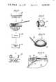
- FIG. 1is a perspective view of a portion of a knee joint prosthesis
- FIG. 2is a bottom view showing the knee joint prosthesis of FIG. 1;
- FIG. 3is an enlarged, fragmentary, sectional view taken along the line 3--3 of FIG. 2;
- FIG. 4is a front view showing a ball-containing portion of a hip joint prosthesis
- FIG. 5is an enlarged sectional view taken along line 5--5 of FIG. 4;
- FIG. 6is a view similar to FIG. 4 showing an alternative embodiment of such a hip joint prosthesis
- FIG. 7is a sectional view through a bone pin
- FIG. 8is a diagrammatic representation showing the formation of a tubular prosthetic device structure having closely controlled porosity
- FIG. 9is a perspective view showing a Starr-Edwards ball-type heart valve which has been modified in accordance with the present invention.
- FIG. 10is a diagrammatic view showing the application of a fine helical coil spring to the base of the valve shown in FIG. 9 by winding the same thereabout;
- FIG. 11is an enlarged fragmentary sectional view showing the heart valve of FIG. 9 with the ball located in closed position.
- FIG. 1 of the drawingsShown in FIG. 1 of the drawings is a knee joint prosthesis 10 designed for replacement of a seriously damaged knee.
- the prosthesis 10has a pivotal wear surface 12 which is of generally arcuate shape and which is flanked by a pair of generally flat side surfaces 14.
- the arcuate surface 12is designed for pivoting against another such arcuate wear surface in the functioning of the knee joint, and there is only a slight curvature between the lateral sides 14 in order to restrict pivoting in that direction and thus attempt to stabilize the knee joint against sideward movement.
- the prosthesis 10has an undersurface 16 which is nominally flat but which is provided with a plurality of parallel shallow grooves 18.
- the grooves 18run from the front to the rear of the prosthesis; however, it should be understood that the parallel grooves could also run from side-to-side, diagonally or in any desired direction.
- the grooves 18accordingly have a depth less than one-half the loop diameter of the springs 20.
- the prosthesis 10may be formed by machining a suitable block of corrosion-resistant metal, and usually metal alloys such as stainless steel, Vitallium, and cobalt alloys, for example, Haynes alloy No. 25, or titanium are employed.
- the coil spring 20is preferably made from the same metal as the remainder of the prosthesis; however, in some cases dissimilar metals are sometimes employed.
- a spring 20is chosen which is formed so that the adjacent loops of the helix abut one another.
- the inherent compression characteristicscauses adjacent springs to grasp one another at the points of contact when the elongating force is removed.
- a helical spring of suitable lengthwould be disposed in each of the shallow grooves 18 and in such grasping contact with the adjacent springs.
- the block and spring assemblymay then be held together, using a suitable jig, and heated to a sintering temperature under a non-oxidizing atmosphere, preferably hydrogen or vacuum.
- helical coil springs 20allows the porosity of the surface to be controlled by the regulation of several parameters. Change in porosity can be accomplished by varying the wire diameter of the metal from which the coil springs are fabricated, by varying the loop diameter of the individual helices and by varying the amount of overlap or interleaving between adjacent springs. Moreover, porosity can be changed by stretching the individual springs to a greater degree so as to provide spacing of a greater distance between loops; however, such stretching to achieve porosity variance is more suitable to the constructions described hereinafter than to the creation of a surface such as that depicted in FIGS. 1 through 3 wherein the interleaving of adjacent springs occurs.
- the natural bone joint portion corresponding to the prosthesis 10is surgically removed, and the remaining end of the bone is shaped to provide a mating face that will fit with the undersurface of the prosthesis that is provided by the coil spring arrangement.
- the uniform and controlled porosity of the undersurfaceis conducive to the growth of natural bone and tissue in adherence thereto, and its presence induces acceptance of the replacement prosthesis as a functionally permanent section of the bone itself.
- the prosthesis 10can be used in its metallic form, or the entire exterior surface thereof can be coated with a more biocompatible material, such as vapor-deposited carbon or certain polymers.
- a more biocompatible materialsuch as vapor-deposited carbon or certain polymers.
- chemical-vapor-deposited carbonas a coating for prosthetic devices generally is disclosed in U.S. Pat. No. 3,526,005, issued Sept. 1, 1970 in the names of Jack C. Bokros, et al.
- a preferred method for assuring good adhesion of a vapor-deposited coating to a metallic substrateis taught in pending U.S. patent application Ser. No. 527,971, filed Nov. 29, 1974 in the names of Jack C. Bokros, et al., now U.S. Pat. No. 3,952,334, issued Apr.
- an intermediate layer of a high-temperature polymerfor example, a polyimide resin or a (polyamide-imide) resin
- non-chemical vapor-deposition methodssuch as vacuum evaporation or sputtering from a pure carbon source.
- the outer layer of vapor-deposited carbonneed only be a fraction of a micron thick, and if such an intermediate polymer layer between about 0.2 and 10 microns thick is used, the thickness of the vapor-deposited carbon layer may be used thin as about 0.2 micron for carbon having a density of at least 1.6 g./cm 3 .
- a hip joint prosthesis 22which has a ball section 24 fabricated from a suitable metal or ceramic material which is suitably proportioned and polished to provide a low friction surface for installation within the hip socket of a living person.
- a ball section 24fabricated from a suitable metal or ceramic material which is suitably proportioned and polished to provide a low friction surface for installation within the hip socket of a living person.
- fastened to the ball section 24is depending collar 26 and shank section 28, preferably formed of metal, which may be joined thereto in any suitable manner (not shown), as by providing the shank 28 and collar 26 with a short threaded stub at its upper end which mates with a threaded hole provided internally within the ball.
- the tapered shank 28is designed for insertion into the upper end of the femur which is being partially replaced by the prosthesis.
- the outer surface of the shank 28is provided with a plurality of channels or grooves 30 which extend longitudinally thereof. Because of the tapered configuration of the shank 28, there are more channels 30 at the upper end than near the lower end thereof.
- An individual helical coil spring 32 of constant loop diameteris disposed in each of the channels 30 to provide the porous surface region into which bone fibers may grow. As illustrated in FIG. 5, the depth of the channels is preferably near the loop diameter of the spring; however, in specialized cases it may be appropriate to use a shallow groove or even none at all.
- the channels 30should not have a depth greater than 150% of the diameter of the helical springs 32.
- the individual springs 32may be initially located in the channels in any suitable manner; however, inasmuch as they are mounted throughout 360° about the surface of the shank, initial spot welding of the ends is sometimes employed. Moreover, such spot welding facilitates slightly stretching helical springs, which are originally formed with their individual loops touching one another, so as to slightly lengthen the springs and thus provide a predetermined amount of spacing between the individual loops thereof, equal to at least about 10% of the diameter of the spring wire.
- each of the springs 32lies in its respective channel 30
- a suitable sintering operationis carried out so that the touching portion of each spring loop becomes permanently bonded to the metal surface of the channel in the shank section 28, thus securing the spring to the substrate at a plurality of spaced points.
- FIG. 6depicts an alternative embodiment of a hip joint prosthesis 22' to that depicted in FIGS. 4 and 5, and accordingly like reference numerals are employed for the same parts.
- a shank section 28'is provided which is provided with a single spiral channel 30' which runs continuously from a location near the top of the shank to the bottom thereof.
- a long coil spring 32'is used, and it may be suitably spot-welded at its one end to a location near the upper end of the channel 30' in the shank. Thereafter it is wrapped around and around the shank 28' along the spiral path, until it reaches the bottom end of the channel.
- Wrappingis carried out with the desired amount of tension in the spring 32' so as to spread apart the individual loops and to provide an amount of spacing to achieve the porosity which is desired. Thereafter, a sintering operation is carried out so as to bond the touching portions of the coil in the channel to the adjacent arcuate surface.
- this spacingcan be increased or decreased, as desired, so as to vary the percentage of porous region provided on the shank portion of the prosthesis 22'. Conceivably the entire surface could be covered with a spiral winding of the spring 32', but likely a porous region this great in area would not be needed.
- FIG. 7depicts a simple bone pin 40 or the like wherein a cylindrical metallic rod 42 is inserted into the interior passageway through a helical spring 44 of constant diameter.
- the spring 44should be proportioned so as not to be significantly oversize with regard to the outer diameter of the metal rod 42 so that a good bond will be created during the subsequent sintering operaion.
- a coil spring 44is chosen having an internal diameter which is substantially equal to the outer diameter of the rod, and after insertion, the spring is stretched the desired amount and tack-welded at each end prior to sintering.
- the individual loops of the springare spaced apart at least about 10% of the diameter of the spring wire, and preferably the diameter of the spring wire is equal to between about 1 and about 5 percent of the diameter of the rod 42.
- a spring 44may be chosen that has a slightly smaller internal diameter, in which case the spring is caused to unwrap slightly, by relative rotation of its opposite ends, to open up the diameter through the helical spring to a sufficient distance to accept the cylindrical rod 42. Thereafter, releasing the ends of the spring 44 causes it to firmly grasp the rod throughout its entire length and thereby obviates the need for tack-welding prior to sintering. In any event, once the sintering is completed, there are points of attachment between the spring and the surface of the rod throughout the lengths thereof.
- FIG. 8diagrammatically illustrates a process for forming a porous tube 50 which is generated by winding a long length of helical spring 52 of constant loop diameter about a suitable mandrel 54 and then joining the spring convolutions to one another to create a self-supporting structure.
- a suitable ceramic mandrel 54is chosen, such as an alumina rod, which will not react with the metal spring at the sintering temperature and which has an external diameter equal to the internal diameter of the desired tube which is to be fabricated.
- the rod 54may be somewhat greater in length than the tube 50 to be fabricated, and one end may be inserted in a lathe or the like so as to aid in its manipulation.
- One end of the spring 52is suitably attached to the rod 54, and the helical spring is then wrapped spirally around the rod as the lathe slowly causes it to rotate, stretching the spring slightly to open up the loops and preferably to just slightly interleave the loops of one spiral convolution with the next. Wrapping is continued until the desired amount of length of the rod 54 is covered, and then the other end of the spring is also suitably affixed to the alumina rod.
- the assemblyis transferred to a sintering station 58 where heating under an inert atmosphere is carried out so that the interleaved coils sinter to one another at the points of touching. There should be no significant reaction between the spring 56 and the ceramic mandrel 54 at the temperature employed. After sintering is complete, the bonds at the two ends are broken at an appropriate machining staion 60, and the alumina rod is removed from the interior of the coiled spring 56.
- the resultant productis a tubular structure 50 having a predetermined porosity, which is a function of the diameter of the spring wire, the loop diameter of the helix, the amount of stretching of the spring during its initial placement and the distance to which the spiral convolutions are interleaved with one another.
- the porous tubular structure 50may be used as is, or it may be entirely coated, for example, with vapor-deposited carbon to make it more biocompatible.
- FIG. 9Shown in FIG. 9 is a heart valve 70 of the Starr-Edwards design, the general details of which are described in U.S. Pat. No. 3,365,728, issued Jan. 30, 1968.
- the valveincludes a base ring 72 upon which is mounted a cage 74 wherein there is disposed a ball valve member 76.
- the ringis preferably made of a non-corrodable metal, such as Stellite, and is shaped to provide an outwardly facing channel 78 about its outer periphery.
- Some type of a sleevehas previously been provided in the channel 78 to permit the heart valve 70 to be sutured in place in the body of the patient. However, in this embodiment of the invention, the sleeve is replaced by a wound helical spring.
- an endless length of a very fine metal wire spring 80has one end suitably attached to the channeled-surface of the ring, as by spot welding, and the helical spring is then wrapped around and around and around the outer periphery of the base ring so as to substantially fill the channel 78 with a plurality of convolutions of the spring.
- the spring 80is slightly stretched so that the loops are spaced apart and interfit with one another as described with respect to FIG. 8.
- the other end of the spring 80is suitably welded to one of the earlier convolutions.
- the base ring 72 with the fine spring wrapped around itis transferred to a sintering station where it is heated under an inert atmosphere so that the slightly interleaved coils sinter to one another at the points of touching.
- the helical spring 80might be made from stainless steel wire between about 0.25 and 0.5mm in diameter which is coiled to have an outer loop diameter of about 2mm.
- the base ring 72 with its wrapped and sintered spring 80may be coated with vapor-deposited carbon. Thereafter, the ball valve member 76 and the cage 74 are mated with the base ring 72, and the struts of the cage permanently joined to the ring. In the implantation of the valve in the mitral position, the porous structure provided by the sintered spring assembly allows ready suturing to the tissue. Thereafter, the carboncoated porous spring structure provides a ready location for the ingrowth of tissue which unites the valve 70 to the heart and results in an excellent and secure affixing of the valve in place.
Landscapes
- Health & Medical Sciences (AREA)
- Cardiology (AREA)
- Engineering & Computer Science (AREA)
- Biomedical Technology (AREA)
- Life Sciences & Earth Sciences (AREA)
- Public Health (AREA)
- Heart & Thoracic Surgery (AREA)
- Vascular Medicine (AREA)
- Oral & Maxillofacial Surgery (AREA)
- Animal Behavior & Ethology (AREA)
- General Health & Medical Sciences (AREA)
- Transplantation (AREA)
- Veterinary Medicine (AREA)
- Gastroenterology & Hepatology (AREA)
- Pulmonology (AREA)
- Orthopedic Medicine & Surgery (AREA)
- Prostheses (AREA)
- Materials For Medical Uses (AREA)
Abstract
Description
Claims (14)
Priority Applications (8)
| Application Number | Priority Date | Filing Date | Title |
|---|---|---|---|
| US05/631,868US4038703A (en) | 1975-11-14 | 1975-11-14 | Prosthetic devices having a region of controlled porosity |
| CA260,837ACA1081402A (en) | 1975-11-14 | 1976-09-09 | Prosthetic devices and methods of making same |
| CH1422376ACH607918A5 (en) | 1975-11-14 | 1976-11-11 | |
| GB47232/76AGB1554454A (en) | 1975-11-14 | 1976-11-12 | Implantable prosthetic device having a region of controlled porosity and method for making same |
| JP51135497AJPS5264198A (en) | 1975-11-14 | 1976-11-12 | Prosthesis and method of producing same |
| DE19762651792DE2651792A1 (en) | 1975-11-14 | 1976-11-12 | PROSTHETIC DEVICE AND METHOD OF MANUFACTURING IT |
| FR7634091AFR2331320A1 (en) | 1975-11-14 | 1976-11-12 | PROSTHESIS WITH A POROUS REGION CARRIED OUT BY A BUDDIN SPRING AND ASSOCIATED PREPARATION PROCESS |
| IT69715/76AIT1091068B (en) | 1975-11-14 | 1976-11-12 | PROSTHETIC DEVICE FOR ORTHOPEDICS AND PROCEDURE FOR ITS MANUFACTURE |
Applications Claiming Priority (1)
| Application Number | Priority Date | Filing Date | Title |
|---|---|---|---|
| US05/631,868US4038703A (en) | 1975-11-14 | 1975-11-14 | Prosthetic devices having a region of controlled porosity |
Publications (1)
| Publication Number | Publication Date |
|---|---|
| US4038703Atrue US4038703A (en) | 1977-08-02 |
Family
ID=24533103
Family Applications (1)
| Application Number | Title | Priority Date | Filing Date |
|---|---|---|---|
| US05/631,868Expired - LifetimeUS4038703A (en) | 1975-11-14 | 1975-11-14 | Prosthetic devices having a region of controlled porosity |
Country Status (8)
| Country | Link |
|---|---|
| US (1) | US4038703A (en) |
| JP (1) | JPS5264198A (en) |
| CA (1) | CA1081402A (en) |
| CH (1) | CH607918A5 (en) |
| DE (1) | DE2651792A1 (en) |
| FR (1) | FR2331320A1 (en) |
| GB (1) | GB1554454A (en) |
| IT (1) | IT1091068B (en) |
Cited By (77)
| Publication number | Priority date | Publication date | Assignee | Title |
|---|---|---|---|---|
| US4292694A (en)* | 1980-06-25 | 1981-10-06 | Lord Corporation | Prosthesis anchoring means |
| US4292695A (en)* | 1980-06-25 | 1981-10-06 | Lord Corporation | Prosthesis stem |
| US4394370A (en)* | 1981-09-21 | 1983-07-19 | Jefferies Steven R | Bone graft material for osseous defects and method of making same |
| US4406023A (en)* | 1982-04-19 | 1983-09-27 | Harris William H | Stemmed femoral component for the human hip |
| US4495664A (en)* | 1981-07-30 | 1985-01-29 | Ceraver | Titanium or titanium alloy pin for cement-free fixing in a long bone to form a prosthesis |
| US4551863A (en)* | 1981-09-28 | 1985-11-12 | Murray William M | Femoral component and method |
| US4570271A (en)* | 1981-07-27 | 1986-02-18 | Battelle Development Corporation | Porous coatings from wire mesh for bone implants |
| US4660755A (en)* | 1985-09-09 | 1987-04-28 | Zimmer, Inc. | Method for constructing a surgical implant |
| GB2184458A (en)* | 1985-11-27 | 1987-06-24 | Permelec Electrode Ltd | Titanium composite having a coil-shaped skeletal surface structure for use as electrode biocompatible implant and catalyst support |
| US4714470A (en)* | 1986-02-19 | 1987-12-22 | Zimmer, Inc. | Grooved prosthetic implant |
| US4714473A (en)* | 1985-07-25 | 1987-12-22 | Harrington Arthritis Research Center | Knee prosthesis |
| US4728335A (en)* | 1986-12-15 | 1988-03-01 | Jurgutis John A | Hip prosthesis |
| US4731088A (en)* | 1986-06-02 | 1988-03-15 | Boehringer Mannheim Corp | Enclosure member for prosthetic joint |
| US4769032A (en)* | 1986-03-05 | 1988-09-06 | Bruce Steinberg | Prosthetic valve and monitoring system and method |
| EP0224890A3 (en)* | 1985-12-05 | 1989-03-15 | Technische Hochschule Karl-Marx-Stadt | Active implant |
| US4829152A (en)* | 1987-11-16 | 1989-05-09 | Rostoker, Inc. | Method of resistance welding a porous body to a substrate |
| US4842517A (en)* | 1986-12-05 | 1989-06-27 | Haruyuki Kawahara | Endosseous implant having mesh pore structure |
| US4936863A (en)* | 1988-05-13 | 1990-06-26 | Hofmann Aaron A | Hip prosthesis |
| US4944759A (en)* | 1986-01-21 | 1990-07-31 | Joint Medical Products Corporation | Porous-coated artificial joints |
| US4964868A (en)* | 1985-07-25 | 1990-10-23 | Harrington Arthritis Research Center | Knee prosthesis |
| US4969907A (en)* | 1985-01-08 | 1990-11-13 | Sulzer Brothers Limited | Metal bone implant |
| US5084151A (en)* | 1985-11-26 | 1992-01-28 | Sorin Biomedica S.P.A. | Method and apparatus for forming prosthetic device having a biocompatible carbon film thereon |
| US5163953A (en)* | 1992-02-10 | 1992-11-17 | Vince Dennis J | Toroidal artificial heart valve stent |
| US5167502A (en)* | 1986-12-05 | 1992-12-01 | Haruyuki Kawahara | Method for an endosseous implant having mesh pore structure |
| US5370684A (en)* | 1986-12-12 | 1994-12-06 | Sorin Biomedica S.P.A. | Prosthesis of polymeric material coated with biocompatible carbon |
| US5387247A (en)* | 1983-10-25 | 1995-02-07 | Sorin Biomedia S.P.A. | Prosthetic device having a biocompatible carbon film thereon and a method of and apparatus for forming such device |
| US5397359A (en)* | 1991-08-07 | 1995-03-14 | Oscobal Ag | Metal wire structure for endoprosthetics |
| US5405402A (en)* | 1993-04-14 | 1995-04-11 | Intermedics Orthopedics, Inc. | Implantable prosthesis with radiographic marker |
| US5411552A (en)* | 1990-05-18 | 1995-05-02 | Andersen; Henning R. | Valve prothesis for implantation in the body and a catheter for implanting such valve prothesis |
| US5489306A (en)* | 1995-01-03 | 1996-02-06 | Gorski; Jerrold M. | Graduated porosity implant for fibro-osseous integration |
| US5549705A (en)* | 1993-10-26 | 1996-08-27 | Howmedica, Inc. | Prosthesis with integral proximal spacer |
| US5653727A (en)* | 1987-10-19 | 1997-08-05 | Medtronic, Inc. | Intravascular stent |
| WO1998019617A1 (en)* | 1996-11-01 | 1998-05-14 | The Johns Hopkins University | Orthopedic implant |
| US5755687A (en)* | 1997-04-01 | 1998-05-26 | Heartport, Inc. | Methods and devices for occluding a patient's ascending aorta |
| US5765568A (en)* | 1994-05-27 | 1998-06-16 | Heartport, Inc. | Catheter system and method for venting the left ventricle |
| EP0730681A4 (en)* | 1993-11-15 | 1998-07-15 | Univ Pennsylvania | Composite materials using bone bioactive glass and ceramic fibers |
| US5792094A (en)* | 1991-07-16 | 1998-08-11 | Heartport, Inc. | Method of delivering cardioplegic fluid to a patient's heart |
| US5881443A (en)* | 1996-12-09 | 1999-03-16 | The Johns Hopkins University | Apparatus and methods for embedding a biocompatible material in a polymer bone implant |
| US5984968A (en)* | 1995-09-29 | 1999-11-16 | Park; Joon B. | Reinforcement for an orthopedic implant |
| US6121172A (en)* | 1993-11-15 | 2000-09-19 | The Trustees Of The University Of Pennsylvania | Composite materials using bone bioactive glass and ceramic fibers |
| US6231590B1 (en) | 1998-11-10 | 2001-05-15 | Scimed Life Systems, Inc. | Bioactive coating for vaso-occlusive devices |
| US6338735B1 (en) | 1991-07-16 | 2002-01-15 | John H. Stevens | Methods for removing embolic material in blood flowing through a patient's ascending aorta |
| US20020151970A1 (en)* | 1999-02-10 | 2002-10-17 | Garrison Michi E. | Methods and devices for implanting cardiac valves |
| US6482171B1 (en) | 1991-07-16 | 2002-11-19 | Heartport, Inc. | Multi-lumen catheter |
| US20030018381A1 (en)* | 2000-01-25 | 2003-01-23 | Scimed Life Systems, Inc. | Manufacturing medical devices by vapor deposition |
| US6582462B1 (en) | 1990-05-18 | 2003-06-24 | Heartport, Inc. | Valve prosthesis for implantation in the body and a catheter for implanting such valve prosthesis |
| US6596084B1 (en) | 1999-05-20 | 2003-07-22 | Medicalcv, Inc. | Pyrolytic carbon coating apparatus having feed gas actuator |
| FR2835739A1 (en)* | 2002-02-11 | 2003-08-15 | Spinevision | SYSTEM FOR FIXING A WORKPIECE ON A BONE BODY |
| US20030220696A1 (en)* | 2002-05-23 | 2003-11-27 | Levine David Jerome | Implantable porous metal |
| US20040093014A1 (en)* | 1998-11-10 | 2004-05-13 | Hanh Ho | Bioactive components for incorporation with vaso-occlusive members |
| US20050102034A1 (en)* | 1998-05-14 | 2005-05-12 | E. Hayes Daniel E.Jr. | Bimetal acetabular component construct for hip joint prosthesis |
| US6915169B2 (en) | 1998-07-22 | 2005-07-05 | Cardiac Pacemakers, Inc. | Extendable and retractable lead having a snap-fit terminal connector |
| US6983185B2 (en) | 1998-07-22 | 2006-01-03 | Cardiac Pacemakers, Inc. | Lead with terminal connector assembly |
| US20060178751A1 (en)* | 1998-05-14 | 2006-08-10 | Despres Alfred S Iii | Implant with composite coating |
| US20060184246A1 (en)* | 2004-06-10 | 2006-08-17 | Zwirkoski Paul A | Non-soft tissue repair |
| US20060189999A1 (en)* | 2005-02-24 | 2006-08-24 | Paul Zwirkoski | Linked slideable and interlockable rotatable components |
| EP1638483A4 (en)* | 2003-06-30 | 2007-04-11 | David Peter Shaw | Cuffs for medical applications |
| US20080021565A1 (en)* | 1998-05-14 | 2008-01-24 | Hayes Daniel E E Jr | Bimetal tibial component construct for knee joint prosthesis |
| US20110208189A1 (en)* | 2005-02-22 | 2011-08-25 | Tecres S.P.A. | Disposable device for treatment of infections of human limbs |
| US8992531B2 (en) | 2011-12-16 | 2015-03-31 | Chow Ip, Llc | Prosthetic femoral stem for use in high impact hip replacement |
| US20150245912A1 (en)* | 2012-09-21 | 2015-09-03 | Waldemar Link Gmbh & Co. Kg | Joint Implant |
| US9301765B2 (en) | 2011-12-16 | 2016-04-05 | Chow Ip, Llc | Prosthetic femoral stem for use in high offset hip replacement |
| US20160101275A1 (en)* | 2014-10-08 | 2016-04-14 | Alfred E. Mann Foundation For Scientific Research | Percutaneous Ports with Wire Coils |
| US20160101274A1 (en)* | 2014-10-08 | 2016-04-14 | Alfred E. Mann Foundation For Scientific Research | Method of Manufacturing Percutaneous Ports with Wire Coils |
| US11278412B2 (en)* | 2018-03-30 | 2022-03-22 | Depuy Ireland Unlimited Company | Hybrid fixation features for three-dimensional porous structures for bone ingrowth and methods for producing |
| US11364123B2 (en) | 2018-03-26 | 2022-06-21 | Depuy Ireland Unlimited Company | Three-dimensional porous structures for bone ingrowth and methods for producing |
| US11517438B2 (en) | 2019-09-25 | 2022-12-06 | Depuy Ireland Unlimited Company | Three-dimensional porous structures for bone ingrowth and methods for producing |
| US11793652B2 (en) | 2017-11-21 | 2023-10-24 | Institute for Musculoskeletal Science and Education, Ltd. | Implant with improved bone contact |
| US11819419B2 (en)* | 2015-04-29 | 2023-11-21 | Institute for Musculoskeletal Science and Education, Ltd. | Implant with curved bone contacting elements |
| US11826261B2 (en) | 2015-04-29 | 2023-11-28 | Institute for Musculoskeletal Science and Education, Ltd. | Coiled implants and systems and methods of use thereof |
| US11890200B2 (en) | 2018-03-30 | 2024-02-06 | Depuy Ireland Unlimited Company | Surface textures for three-dimensional porous structures for bone ingrowth and methods for producing |
| US11938039B2 (en) | 2017-03-13 | 2024-03-26 | Institute for Musculoskeletal Science and Education, Ltd. | Implant with structural members arranged around a ring |
| US11951018B2 (en) | 2017-11-21 | 2024-04-09 | Institute for Musculoskeletal Science and Education, Ltd. | Implant with improved flow characteristics |
| US12042399B2 (en) | 2016-10-25 | 2024-07-23 | Institute for Musculoskeletal Science and Education, Ltd. | Implant with protected fusion zones |
| US12097123B2 (en) | 2015-04-29 | 2024-09-24 | Institute for Musculoskeletal Science and Education, Ltd. | Implant with arched bone contacting elements |
| US12171464B2 (en)* | 2022-05-06 | 2024-12-24 | Lincotek Trento S.P.A. | Fixing device |
| US12208011B2 (en) | 2016-10-25 | 2025-01-28 | Institute for Musculoskeletal Science and Education, Ltd. | Implant with multi-layer bone interfacing lattice |
Families Citing this family (17)
| Publication number | Priority date | Publication date | Assignee | Title |
|---|---|---|---|---|
| FR2429589A1 (en)* | 1978-06-29 | 1980-01-25 | Ceraver | TITANIUM ROD OR TITANIUM ALLOY FOR CEMENT-FREE FIXING IN A LONG BONE FOR PROSTHESIS |
| FR2510395B2 (en)* | 1978-06-29 | 1987-05-29 | Ceraver | TITANIUM ROD OR TITANIUM ALLOY FOR CEMENT-FREE FIXING IN A LONG BONE FOR PROSTHESIS |
| US4479271A (en)* | 1981-10-26 | 1984-10-30 | Zimmer, Inc. | Prosthetic device adapted to promote bone/tissue ingrowth |
| DE3216539C3 (en)* | 1982-05-03 | 1997-09-25 | Link Waldemar Gmbh Co | Thigh part of a hip joint endoprosthesis |
| US4546501A (en)* | 1982-09-28 | 1985-10-15 | Gustilo Ramon B | Hip prosthesis |
| USRE32488E (en)* | 1982-09-28 | 1987-09-01 | Hip prosthesis | |
| GB8318483D0 (en)* | 1983-07-08 | 1983-08-10 | Zimmer Deloro Surgical Ltd | Skeletal implants |
| US4536894A (en)* | 1983-08-04 | 1985-08-27 | Galante Jorge O | Hip prosthesis with flared porous bony ingrowth pads |
| FR2565482A2 (en)* | 1984-06-07 | 1985-12-13 | Biomasys | Improvements made to intra-uterine devices |
| FR2555893A1 (en)* | 1983-12-01 | 1985-06-07 | Biomasys | Improvements made to intra-uterine devices |
| EP0147274A1 (en)* | 1983-12-01 | 1985-07-03 | BIOMASYS Société dite: | Intra-uterine devices |
| KR850001814B1 (en)* | 1984-04-17 | 1985-12-23 | 한국과학기술원 | Total hip arthroplasty |
| DE3423667A1 (en)* | 1984-05-08 | 1985-11-28 | Rüdiger Dipl.-Ing. 5204 Lohmar Scheunemann | IMPLANT FOR BONE AND TOOTH ROOT REPLACEMENT WITH SPECIAL TRANSITION STRUCTURE BETWEEN BONES AND IMPLANT CORE AND BONE SIDE WHOLE OR PARTLY RESORBABLE MATRIX |
| FR2573648B1 (en)* | 1984-11-28 | 1989-07-13 | Rousseau Philippe | CEMENT-FREE SMOOTH RAIL PROSTHESIS OF THE TOP END OF THE FEMUR |
| FR2610512B1 (en)* | 1987-02-06 | 1997-01-24 | Cuilleron J | METHOD AND MEANS FOR ANCHORING ELEMENTS OF SCREWED IMPLANTS IN BONE TISSUES AND THE IMPLANT ELEMENTS OBTAINED |
| CH689725A5 (en)* | 1994-09-08 | 1999-09-30 | Franz Dr Sutter | Condyle prosthesis. |
| DE4441695A1 (en)* | 1994-11-23 | 1996-06-13 | Gerd Hoermansdoerfer | Anisotropically elastic hip joint endoprosthesis for implantation in narrow space of upper leg bone |
Citations (5)
| Publication number | Priority date | Publication date | Assignee | Title |
|---|---|---|---|---|
| BE560269A (en)* | ||||
| US3435526A (en)* | 1967-02-13 | 1969-04-01 | Heli Coil Corp | Device for securing an artificial tooth to the bone structure of a human jaw |
| US3546711A (en)* | 1968-04-09 | 1970-12-15 | Gulf Energy & Environ Systems | Heart valve |
| US3839741A (en)* | 1972-11-17 | 1974-10-08 | J Haller | Heart valve and retaining means therefor |
| US3906550A (en)* | 1973-12-27 | 1975-09-23 | William Rostoker | Prosthetic device having a porous fiber metal structure |
Family Cites Families (7)
| Publication number | Priority date | Publication date | Assignee | Title |
|---|---|---|---|---|
| GB1073076A (en)* | 1964-12-31 | 1967-06-21 | Nat Res Dev | An improved artificial heart valve |
| CH430043A (en)* | 1965-10-19 | 1967-02-15 | Adriano Dr Bertolini | Procedure for obtaining an intraosseous implant for dental prosthesis and an intraosseous implant thus obtained |
| GB1165698A (en)* | 1965-11-05 | 1969-10-01 | Guinness De Laszlo M A P Henry | Improvements in or relating to Prostheses |
| US3707006A (en)* | 1970-08-26 | 1972-12-26 | Gulf Oil Corp | Orthopedic device for repair or replacement of bone |
| FR2215927B1 (en)* | 1973-01-31 | 1976-05-14 | Louyot Comptoir Lyon Alemand | |
| US3969130A (en)* | 1973-02-05 | 1976-07-13 | General Atomic Company | Carbon-coated articles and method of making same |
| FR2307516A1 (en)* | 1975-04-18 | 1976-11-12 | Giraux Jean | Artificial valve for heart - has seamless titanium sleeve with U-shaped orifices opened by folding tongues |
- 1975
- 1975-11-14USUS05/631,868patent/US4038703A/ennot_activeExpired - Lifetime
- 1976
- 1976-09-09CACA260,837Apatent/CA1081402A/ennot_activeExpired
- 1976-11-11CHCH1422376Apatent/CH607918A5/xxnot_activeIP Right Cessation
- 1976-11-12DEDE19762651792patent/DE2651792A1/ennot_activeWithdrawn
- 1976-11-12GBGB47232/76Apatent/GB1554454A/ennot_activeExpired
- 1976-11-12JPJP51135497Apatent/JPS5264198A/enactivePending
- 1976-11-12ITIT69715/76Apatent/IT1091068B/enactive
- 1976-11-12FRFR7634091Apatent/FR2331320A1/enactiveGranted
Patent Citations (5)
| Publication number | Priority date | Publication date | Assignee | Title |
|---|---|---|---|---|
| BE560269A (en)* | ||||
| US3435526A (en)* | 1967-02-13 | 1969-04-01 | Heli Coil Corp | Device for securing an artificial tooth to the bone structure of a human jaw |
| US3546711A (en)* | 1968-04-09 | 1970-12-15 | Gulf Energy & Environ Systems | Heart valve |
| US3839741A (en)* | 1972-11-17 | 1974-10-08 | J Haller | Heart valve and retaining means therefor |
| US3906550A (en)* | 1973-12-27 | 1975-09-23 | William Rostoker | Prosthetic device having a porous fiber metal structure |
Cited By (119)
| Publication number | Priority date | Publication date | Assignee | Title |
|---|---|---|---|---|
| US4292695A (en)* | 1980-06-25 | 1981-10-06 | Lord Corporation | Prosthesis stem |
| US4292694A (en)* | 1980-06-25 | 1981-10-06 | Lord Corporation | Prosthesis anchoring means |
| US4570271A (en)* | 1981-07-27 | 1986-02-18 | Battelle Development Corporation | Porous coatings from wire mesh for bone implants |
| US4495664A (en)* | 1981-07-30 | 1985-01-29 | Ceraver | Titanium or titanium alloy pin for cement-free fixing in a long bone to form a prosthesis |
| US4394370A (en)* | 1981-09-21 | 1983-07-19 | Jefferies Steven R | Bone graft material for osseous defects and method of making same |
| US4551863A (en)* | 1981-09-28 | 1985-11-12 | Murray William M | Femoral component and method |
| US4406023A (en)* | 1982-04-19 | 1983-09-27 | Harris William H | Stemmed femoral component for the human hip |
| US5387247A (en)* | 1983-10-25 | 1995-02-07 | Sorin Biomedia S.P.A. | Prosthetic device having a biocompatible carbon film thereon and a method of and apparatus for forming such device |
| US4969907A (en)* | 1985-01-08 | 1990-11-13 | Sulzer Brothers Limited | Metal bone implant |
| US4964868A (en)* | 1985-07-25 | 1990-10-23 | Harrington Arthritis Research Center | Knee prosthesis |
| US4714473A (en)* | 1985-07-25 | 1987-12-22 | Harrington Arthritis Research Center | Knee prosthesis |
| US4660755A (en)* | 1985-09-09 | 1987-04-28 | Zimmer, Inc. | Method for constructing a surgical implant |
| US5084151A (en)* | 1985-11-26 | 1992-01-28 | Sorin Biomedica S.P.A. | Method and apparatus for forming prosthetic device having a biocompatible carbon film thereon |
| GB2184458A (en)* | 1985-11-27 | 1987-06-24 | Permelec Electrode Ltd | Titanium composite having a coil-shaped skeletal surface structure for use as electrode biocompatible implant and catalyst support |
| US4889685A (en)* | 1985-11-27 | 1989-12-26 | Permelec Electrode Ltd. | Process of producing titanium composite having a coil-shaped skeletal structure on the surface thereof |
| EP0224890A3 (en)* | 1985-12-05 | 1989-03-15 | Technische Hochschule Karl-Marx-Stadt | Active implant |
| US4944759A (en)* | 1986-01-21 | 1990-07-31 | Joint Medical Products Corporation | Porous-coated artificial joints |
| US4714470A (en)* | 1986-02-19 | 1987-12-22 | Zimmer, Inc. | Grooved prosthetic implant |
| US4769032A (en)* | 1986-03-05 | 1988-09-06 | Bruce Steinberg | Prosthetic valve and monitoring system and method |
| US4731088A (en)* | 1986-06-02 | 1988-03-15 | Boehringer Mannheim Corp | Enclosure member for prosthetic joint |
| US5167502A (en)* | 1986-12-05 | 1992-12-01 | Haruyuki Kawahara | Method for an endosseous implant having mesh pore structure |
| US4842517A (en)* | 1986-12-05 | 1989-06-27 | Haruyuki Kawahara | Endosseous implant having mesh pore structure |
| US5370684A (en)* | 1986-12-12 | 1994-12-06 | Sorin Biomedica S.P.A. | Prosthesis of polymeric material coated with biocompatible carbon |
| US4728335A (en)* | 1986-12-15 | 1988-03-01 | Jurgutis John A | Hip prosthesis |
| US5653727A (en)* | 1987-10-19 | 1997-08-05 | Medtronic, Inc. | Intravascular stent |
| US6923828B1 (en) | 1987-10-19 | 2005-08-02 | Medtronic, Inc. | Intravascular stent |
| US4829152A (en)* | 1987-11-16 | 1989-05-09 | Rostoker, Inc. | Method of resistance welding a porous body to a substrate |
| US4936863A (en)* | 1988-05-13 | 1990-06-26 | Hofmann Aaron A | Hip prosthesis |
| US7618446B2 (en) | 1990-05-18 | 2009-11-17 | Edwards Lifesciences Ag | Valve prosthesis for implantation in the body and a catheter for implanting such valve prosthesis |
| US6582462B1 (en) | 1990-05-18 | 2003-06-24 | Heartport, Inc. | Valve prosthesis for implantation in the body and a catheter for implanting such valve prosthesis |
| US5411552A (en)* | 1990-05-18 | 1995-05-02 | Andersen; Henning R. | Valve prothesis for implantation in the body and a catheter for implanting such valve prothesis |
| US6338735B1 (en) | 1991-07-16 | 2002-01-15 | John H. Stevens | Methods for removing embolic material in blood flowing through a patient's ascending aorta |
| US6482171B1 (en) | 1991-07-16 | 2002-11-19 | Heartport, Inc. | Multi-lumen catheter |
| US5792094A (en)* | 1991-07-16 | 1998-08-11 | Heartport, Inc. | Method of delivering cardioplegic fluid to a patient's heart |
| US20020058995A1 (en)* | 1991-07-16 | 2002-05-16 | Stevens John H. | Endovascular aortic valve replacement |
| US8915959B2 (en) | 1991-07-16 | 2014-12-23 | Heartport, Inc. | Endovascular aortic valve replacement |
| US5397359A (en)* | 1991-08-07 | 1995-03-14 | Oscobal Ag | Metal wire structure for endoprosthetics |
| US5163953A (en)* | 1992-02-10 | 1992-11-17 | Vince Dennis J | Toroidal artificial heart valve stent |
| US5405402A (en)* | 1993-04-14 | 1995-04-11 | Intermedics Orthopedics, Inc. | Implantable prosthesis with radiographic marker |
| US5549705A (en)* | 1993-10-26 | 1996-08-27 | Howmedica, Inc. | Prosthesis with integral proximal spacer |
| US6121172A (en)* | 1993-11-15 | 2000-09-19 | The Trustees Of The University Of Pennsylvania | Composite materials using bone bioactive glass and ceramic fibers |
| EP0730681A4 (en)* | 1993-11-15 | 1998-07-15 | Univ Pennsylvania | Composite materials using bone bioactive glass and ceramic fibers |
| US5810757A (en)* | 1994-05-27 | 1998-09-22 | Heartport, Inc. | Catheter system and method for total isolation of the heart |
| US6398752B1 (en) | 1994-05-27 | 2002-06-04 | William P. Sweezer, Jr. | Method of occluding a patient's ascending aorta and delivery cardioplegic fluid |
| US5800375A (en)* | 1994-05-27 | 1998-09-01 | Heartport, Inc. | Catheter system and method for providing cardiopulmonary bypass pump support during heart surgery |
| US5765568A (en)* | 1994-05-27 | 1998-06-16 | Heartport, Inc. | Catheter system and method for venting the left ventricle |
| US5489306A (en)* | 1995-01-03 | 1996-02-06 | Gorski; Jerrold M. | Graduated porosity implant for fibro-osseous integration |
| US5984968A (en)* | 1995-09-29 | 1999-11-16 | Park; Joon B. | Reinforcement for an orthopedic implant |
| US6602293B1 (en)* | 1996-11-01 | 2003-08-05 | The Johns Hopkins University | Polymeric composite orthopedic implant |
| EP0951248A4 (en)* | 1996-11-01 | 2000-11-02 | Univ Johns Hopkins | ORTHOPEDIC PROSTHESIS |
| WO1998019617A1 (en)* | 1996-11-01 | 1998-05-14 | The Johns Hopkins University | Orthopedic implant |
| US5881443A (en)* | 1996-12-09 | 1999-03-16 | The Johns Hopkins University | Apparatus and methods for embedding a biocompatible material in a polymer bone implant |
| US5755687A (en)* | 1997-04-01 | 1998-05-26 | Heartport, Inc. | Methods and devices for occluding a patient's ascending aorta |
| US6056723A (en)* | 1997-04-01 | 2000-05-02 | Heartport, Inc. | Methods and devices for occluding a patient's ascending aorta |
| US6423031B1 (en) | 1997-04-01 | 2002-07-23 | Brian S. Donlon | Methods and devices for occluding a patient's ascending aorta |
| US7850738B2 (en) | 1998-05-14 | 2010-12-14 | Hayes Jr Daniel E E | Bimetal acetabular component construct for hip joint prosthesis |
| US8167954B2 (en) | 1998-05-14 | 2012-05-01 | Consensus Orthopedics, Inc. | Implant with composite coating |
| US20090254191A1 (en)* | 1998-05-14 | 2009-10-08 | Despres Iii Alfred S | Implant with composite coating |
| US7513912B2 (en) | 1998-05-14 | 2009-04-07 | Hayes Medical, Inc. | Bimetal tibial component construct for knee joint prosthesis |
| US7445640B2 (en)* | 1998-05-14 | 2008-11-04 | Hayes Medical, Inc. | Implant with composite coating |
| US20050102034A1 (en)* | 1998-05-14 | 2005-05-12 | E. Hayes Daniel E.Jr. | Bimetal acetabular component construct for hip joint prosthesis |
| US20080021565A1 (en)* | 1998-05-14 | 2008-01-24 | Hayes Daniel E E Jr | Bimetal tibial component construct for knee joint prosthesis |
| US20060178751A1 (en)* | 1998-05-14 | 2006-08-10 | Despres Alfred S Iii | Implant with composite coating |
| US8285398B2 (en) | 1998-07-22 | 2012-10-09 | Cardiac Pacemakers, Inc. | Lead with terminal connector assembly |
| US6983185B2 (en) | 1998-07-22 | 2006-01-03 | Cardiac Pacemakers, Inc. | Lead with terminal connector assembly |
| US6915169B2 (en) | 1998-07-22 | 2005-07-05 | Cardiac Pacemakers, Inc. | Extendable and retractable lead having a snap-fit terminal connector |
| US8209035B2 (en) | 1998-07-22 | 2012-06-26 | Cardiac Pacemakers, Inc. | Extendable and retractable lead having a snap-fit terminal connector |
| US7774934B2 (en) | 1998-07-22 | 2010-08-17 | Cardiac Pacemakers, Inc. | Method for making a terminal connector |
| US7392095B2 (en) | 1998-07-22 | 2008-06-24 | Cardiac Pacemakers, Inc. | Extendable and retractable lead having a snap-fit terminal connector |
| US8016852B2 (en) | 1998-11-10 | 2011-09-13 | Stryker Corporation | Bioactive components for incorporation with vaso-occlusive members |
| US6231590B1 (en) | 1998-11-10 | 2001-05-15 | Scimed Life Systems, Inc. | Bioactive coating for vaso-occlusive devices |
| US20040093014A1 (en)* | 1998-11-10 | 2004-05-13 | Hanh Ho | Bioactive components for incorporation with vaso-occlusive members |
| US20020151970A1 (en)* | 1999-02-10 | 2002-10-17 | Garrison Michi E. | Methods and devices for implanting cardiac valves |
| US6596084B1 (en) | 1999-05-20 | 2003-07-22 | Medicalcv, Inc. | Pyrolytic carbon coating apparatus having feed gas actuator |
| US6938668B2 (en) | 2000-01-25 | 2005-09-06 | Scimed Life Systems, Inc. | Manufacturing medical devices by vapor deposition |
| US8460361B2 (en) | 2000-01-25 | 2013-06-11 | Boston Scientific Scimed, Inc. | Manufacturing medical devices by vapor deposition |
| US20060000715A1 (en)* | 2000-01-25 | 2006-01-05 | Whitcher Forrest D | Manufacturing medical devices by vapor deposition |
| US20030018381A1 (en)* | 2000-01-25 | 2003-01-23 | Scimed Life Systems, Inc. | Manufacturing medical devices by vapor deposition |
| WO2003068112A1 (en)* | 2002-02-11 | 2003-08-21 | Spinevision | System for fixing a part to a bone element |
| FR2835739A1 (en)* | 2002-02-11 | 2003-08-15 | Spinevision | SYSTEM FOR FIXING A WORKPIECE ON A BONE BODY |
| US20050143733A1 (en)* | 2002-02-11 | 2005-06-30 | Dominique Petit | System for fixing a part to a bone element |
| US8142504B2 (en) | 2002-02-11 | 2012-03-27 | Spinevision | System for fixing a part to a bone element |
| US20030220696A1 (en)* | 2002-05-23 | 2003-11-27 | Levine David Jerome | Implantable porous metal |
| EP1638483A4 (en)* | 2003-06-30 | 2007-04-11 | David Peter Shaw | Cuffs for medical applications |
| US8734520B2 (en) | 2004-06-10 | 2014-05-27 | Spinal Ventures, Llc | Device and method for securing a fastener |
| US9526539B2 (en) | 2004-06-10 | 2016-12-27 | Spinal Ventures, Llc | Non-soft tissue repair |
| US20100076497A1 (en)* | 2004-06-10 | 2010-03-25 | Zwirkoski Paul A | Device and Method for Securing a Fastener |
| US7682400B2 (en) | 2004-06-10 | 2010-03-23 | Spinal Ventures, Llc | Non-soft tissue repair |
| US20060184246A1 (en)* | 2004-06-10 | 2006-08-17 | Zwirkoski Paul A | Non-soft tissue repair |
| US20110208189A1 (en)* | 2005-02-22 | 2011-08-25 | Tecres S.P.A. | Disposable device for treatment of infections of human limbs |
| US9452001B2 (en)* | 2005-02-22 | 2016-09-27 | Tecres S.P.A. | Disposable device for treatment of infections of human limbs |
| US8034109B2 (en) | 2005-02-24 | 2011-10-11 | Morphogeny, Llc | Linked slideable and interlockable rotatable components |
| US20060189999A1 (en)* | 2005-02-24 | 2006-08-24 | Paul Zwirkoski | Linked slideable and interlockable rotatable components |
| US9301765B2 (en) | 2011-12-16 | 2016-04-05 | Chow Ip, Llc | Prosthetic femoral stem for use in high offset hip replacement |
| US8992531B2 (en) | 2011-12-16 | 2015-03-31 | Chow Ip, Llc | Prosthetic femoral stem for use in high impact hip replacement |
| US10070963B2 (en) | 2011-12-16 | 2018-09-11 | Chow Ip, Llc | Prosthetic femoral stem for use in high impact hip replacement |
| US9427258B2 (en) | 2011-12-16 | 2016-08-30 | Chow Ip, Llc | Prosthetic femoral stem for use in high impact hip replacement |
| US20150245912A1 (en)* | 2012-09-21 | 2015-09-03 | Waldemar Link Gmbh & Co. Kg | Joint Implant |
| US10226612B2 (en)* | 2014-10-08 | 2019-03-12 | Alfred E. Mann Foundation For Scientific Research | Percutaneous ports with wire coils |
| US20160101274A1 (en)* | 2014-10-08 | 2016-04-14 | Alfred E. Mann Foundation For Scientific Research | Method of Manufacturing Percutaneous Ports with Wire Coils |
| US10086184B2 (en)* | 2014-10-08 | 2018-10-02 | Alfred E. Mann Foundation For Scientific Research | Method of manufacturing percutaneous ports with wire coils |
| US20160101275A1 (en)* | 2014-10-08 | 2016-04-14 | Alfred E. Mann Foundation For Scientific Research | Percutaneous Ports with Wire Coils |
| US10940303B2 (en)* | 2014-10-08 | 2021-03-09 | Alfred E. Mann Foundation For Scientific Research | Percutaneous ports with wire coils |
| US11826261B2 (en) | 2015-04-29 | 2023-11-28 | Institute for Musculoskeletal Science and Education, Ltd. | Coiled implants and systems and methods of use thereof |
| US11819419B2 (en)* | 2015-04-29 | 2023-11-21 | Institute for Musculoskeletal Science and Education, Ltd. | Implant with curved bone contacting elements |
| US12097123B2 (en) | 2015-04-29 | 2024-09-24 | Institute for Musculoskeletal Science and Education, Ltd. | Implant with arched bone contacting elements |
| US12208011B2 (en) | 2016-10-25 | 2025-01-28 | Institute for Musculoskeletal Science and Education, Ltd. | Implant with multi-layer bone interfacing lattice |
| US12042399B2 (en) | 2016-10-25 | 2024-07-23 | Institute for Musculoskeletal Science and Education, Ltd. | Implant with protected fusion zones |
| US12303400B2 (en) | 2017-03-13 | 2025-05-20 | Institute for Musculoskeletal Science and Education, Ltd. | Implant with structural members arranged around a ring |
| US11938039B2 (en) | 2017-03-13 | 2024-03-26 | Institute for Musculoskeletal Science and Education, Ltd. | Implant with structural members arranged around a ring |
| US11793652B2 (en) | 2017-11-21 | 2023-10-24 | Institute for Musculoskeletal Science and Education, Ltd. | Implant with improved bone contact |
| US12186200B2 (en) | 2017-11-21 | 2025-01-07 | Institute for Musculoskeletal Science and Education, Ltd. | Implant with improved bone contact |
| US11951018B2 (en) | 2017-11-21 | 2024-04-09 | Institute for Musculoskeletal Science and Education, Ltd. | Implant with improved flow characteristics |
| US11364123B2 (en) | 2018-03-26 | 2022-06-21 | Depuy Ireland Unlimited Company | Three-dimensional porous structures for bone ingrowth and methods for producing |
| US11890200B2 (en) | 2018-03-30 | 2024-02-06 | Depuy Ireland Unlimited Company | Surface textures for three-dimensional porous structures for bone ingrowth and methods for producing |
| US11278412B2 (en)* | 2018-03-30 | 2022-03-22 | Depuy Ireland Unlimited Company | Hybrid fixation features for three-dimensional porous structures for bone ingrowth and methods for producing |
| US12133801B2 (en) | 2019-09-25 | 2024-11-05 | Depuy Ireland Unlimited Company | Three-dimensional porous structures for bone ingrowth and methods for producing |
| US11517438B2 (en) | 2019-09-25 | 2022-12-06 | Depuy Ireland Unlimited Company | Three-dimensional porous structures for bone ingrowth and methods for producing |
| US12171464B2 (en)* | 2022-05-06 | 2024-12-24 | Lincotek Trento S.P.A. | Fixing device |
Also Published As
| Publication number | Publication date |
|---|---|
| FR2331320A1 (en) | 1977-06-10 |
| CA1081402A (en) | 1980-07-15 |
| GB1554454A (en) | 1979-10-24 |
| JPS5264198A (en) | 1977-05-27 |
| FR2331320B1 (en) | 1982-06-04 |
| CH607918A5 (en) | 1978-12-15 |
| DE2651792A1 (en) | 1977-05-18 |
| IT1091068B (en) | 1985-06-26 |
Similar Documents
| Publication | Publication Date | Title |
|---|---|---|
| US4038703A (en) | Prosthetic devices having a region of controlled porosity | |
| DE69834425T2 (en) | SUPPORTED IMPLANT | |
| US9668852B2 (en) | Metallic implantable grafts and method of making same | |
| US6908480B2 (en) | Structurally variable stents | |
| CA2498162C (en) | Sectional crimped graft | |
| US5015253A (en) | Non-woven endoprosthesis | |
| US4349498A (en) | Radio-opaque markers for pyrolytic carbon prosthetic members | |
| US5163958A (en) | Carbon coated tubular endoprosthesis | |
| US5549663A (en) | Endoprosthesis having graft member and exposed welded end junctions, method and procedure | |
| US3800403A (en) | Method of making a suturing member and mounting the suturing member on a device | |
| EP2298252A1 (en) | Valvular prostheses having metal or pseudometallic construction and methods of manufacture | |
| FR2702954A1 (en) | Prosthesis and intraluminal implant. | |
| WO1993020781A1 (en) | Suture ring for heart valve prosthesis | |
| AU2005267886A1 (en) | Metallic drug-releasing medical devices and method of making same | |
| AU2008201081B8 (en) | Valvular prostheses having metal or pseudometallic construction and methods of manufacture | |
| MX2007000912A (en) | Metallic drug-releasing medical devices and method of making same |
Legal Events
| Date | Code | Title | Description |
|---|---|---|---|
| AS | Assignment | Owner name:CITIBANK, N.A., AS AGENT Free format text:SECURITY INTEREST;ASSIGNORS:INTERMEDICS, INC.;INTERMEDICS CARDIASSIST, INC.;INTERMEDICS INTRAOCULAR, INC.;AND OTHERS;REEL/FRAME:004303/0077 Effective date:19840726 Owner name:CHASE MANHATTAN BANK, N.A., THE Free format text:SECURITY INTEREST;ASSIGNORS:INTERMEDICS, INC.;INTERMEDICS CARDIASSIST, INC.;INTERMEDICS INTRAOCULAR, INC.;AND OTHERS;REEL/FRAME:004303/0077 Effective date:19840726 Owner name:FIRST NATIONAL BANK OF CHICAGO, THE Free format text:SECURITY INTEREST;ASSIGNORS:INTERMEDICS, INC.;INTERMEDICS CARDIASSIST, INC.;INTERMEDICS INTRAOCULAR, INC.;AND OTHERS;REEL/FRAME:004303/0077 Effective date:19840726 Owner name:FIRST FREEPORT NATIONAL BANK Free format text:SECURITY INTEREST;ASSIGNORS:INTERMEDICS, INC.;INTERMEDICS CARDIASSIST, INC.;INTERMEDICS INTRAOCULAR, INC.;AND OTHERS;REEL/FRAME:004303/0077 Effective date:19840726 Owner name:TRUST COMPANY BANK Free format text:SECURITY INTEREST;ASSIGNORS:INTERMEDICS, INC.;INTERMEDICS CARDIASSIST, INC.;INTERMEDICS INTRAOCULAR, INC.;AND OTHERS;REEL/FRAME:004303/0077 Effective date:19840726 Owner name:BANK OF AMERICA NATIONAL TRUST AND SAVINGS ASSOCIA Free format text:SECURITY INTEREST;ASSIGNORS:INTERMEDICS, INC.;INTERMEDICS CARDIASSIST, INC.;INTERMEDICS INTRAOCULAR, INC.;AND OTHERS;REEL/FRAME:004303/0077 Effective date:19840726 Owner name:BRAZOSPORT BANK OF TEXAS Free format text:SECURITY INTEREST;ASSIGNORS:INTERMEDICS, INC.;INTERMEDICS CARDIASSIST, INC.;INTERMEDICS INTRAOCULAR, INC.;AND OTHERS;REEL/FRAME:004303/0077 Effective date:19840726 | |
| AS | Assignment | Owner name:CHASE COMMERCIAL CORPORATION Free format text:SECURITY INTEREST;ASSIGNORS:INTERMEDICS, INC., A CORP. OF TEXAS;INTERMEDICS CARDIASSIST, INC., A CORP OF TX.;INTERMEDICS INTRAOCULAR, INC., A CORP. OF TEXAS;AND OTHERS;REEL/FRAME:004449/0501 Effective date:19850703 Owner name:B.A. LEASING CORPORATION Free format text:SECURITY INTEREST;ASSIGNORS:INTERMEDICS, INC., A CORP. OF TEXAS;INTERMEDICS CARDIASSIST, INC.;INTERMEDICS INTRAOCULAR, INC., A CORP. OF TEXAS;AND OTHERS;REEL/FRAME:004449/0424 Effective date:19850703 Owner name:CITIBANK, N.A. Free format text:SECURITY INTEREST;ASSIGNORS:INTERMEDICS, INC., A TX CORP;INTERMEDICS CARDIASSIST, INC., A TX CORP.;INTERMEDICS INTRAOCULAR, INC., A TX CORP.;AND OTHERS;REEL/FRAME:004434/0728 Effective date:19850703 Owner name:CITICORP MILTILEASE (SEF), INC. Free format text:SECURITY INTEREST;ASSIGNORS:INTERMEDICS, INC.;INTERMEDICS CARDIASSIST, INC.;INTERMEDICS INTRAOCULAR, INC., A CORP. OF TEXAS;AND OTHERS;REEL/FRAME:004452/0900 Effective date:19850703 | |
| AS | Assignment | Owner name:INTERMEDICS, INC. Free format text:RELEASED BY SECURED PARTY;ASSIGNOR:CITICORP MULTILEASE (SEF), INC.;REEL/FRAME:004576/0516 Effective date:19860515 Owner name:INTERMEDICS, INC., INTERMEDICS CARDIASSIST, INC., Free format text:SAID PARTIES RECITES OBLIGATIONS RECITED IN SECURITY AGREEMENT RECORDED SEPTEMBER 17, 1984 REEL 4303 FRAMES 077-127 HAVE BEEN PAID IN FULL ALL;ASSIGNOR:CITIBANK, N.A., INDIVIDUALLY AND AS AGENT FOR BANK OF AMERICA NATIONAL TRUST AND SAVINGS ASSOCIATION, THE CHASE MANHATTAN BANK, N.A., THE FIRST NATIONAL BANK OF CHICAGO, TRUST COMPANY BANK, FIRST FREEPORT NATIONAL BANK OF BRAZOSPORT BANK OF TEXAS;REEL/FRAME:004592/0424 Effective date:19860502 Owner name:INTERMEDICS, INC., INTERMEDICS CARDIASSIST, INC., Free format text:SECURED PARTY HEREBY RELEASE THE SECURITY INTEREST IN AGREEMENT RECORDED AUGUST 5, 1985. REEL 4434 FRAMES 728-782;ASSIGNOR:CITIBANK, N.A.;REEL/FRAME:004592/0394 Effective date:19860502 | |
| AS | Assignment | Owner name:MAY PARTNERSHIP THE, 2170 PIEDMONT ROAD, N.E., ATL Free format text:SECURITY INTEREST;ASSIGNORS:INTERMEDICS, INC.,;INTERMEDICS CARDIASSIST, INC.;SURGITRONICS CORPORATION;AND OTHERS;REEL/FRAME:004581/0501 Effective date:19860703 Owner name:MAY PARTNERSHIP, THE,GEORGIA Free format text:SECURITY INTEREST;ASSIGNORS:INTERMEDICS, INC.,;INTERMEDICS CARDIASSIST, INC.;SURGITRONICS CORPORATION;AND OTHERS;REEL/FRAME:004581/0501 Effective date:19860703 | |
| AS | Assignment | Owner name:INTERMEDICS, INC., A TEXAS CORP. Free format text:RELEASED BY SECURED PARTY;ASSIGNOR:B. A. LEASING CORPORATION;REEL/FRAME:004603/0607 Effective date:19860813 Owner name:INTERMEDICS CARDIASSIST, INC., A TEXAS CORP. Free format text:RELEASED BY SECURED PARTY;ASSIGNOR:B. A. LEASING CORPORATION;REEL/FRAME:004603/0607 Effective date:19860813 Owner name:INTERMEDICS INTRAOCULAR, INC., A TEXAS CORP. Free format text:RELEASED BY SECURED PARTY;ASSIGNOR:B. A. LEASING CORPORATION;REEL/FRAME:004603/0607 Effective date:19860813 Owner name:SURGITRONICS CORPORATION, A TEXAS CORP. Free format text:RELEASED BY SECURED PARTY;ASSIGNOR:B. A. LEASING CORPORATION;REEL/FRAME:004603/0607 Effective date:19860813 Owner name:CARBOMEDICS, INC., A TEXAS CORP. Free format text:RELEASED BY SECURED PARTY;ASSIGNOR:B. A. LEASING CORPORATION;REEL/FRAME:004603/0607 Effective date:19860813 Owner name:NEUROMEDICS, INC., A TEXAS CORP. Free format text:RELEASED BY SECURED PARTY;ASSIGNOR:B. A. LEASING CORPORATION;REEL/FRAME:004603/0607 Effective date:19860813 Owner name:CALCITEK, INC., A TEXAS CORP. Free format text:RELEASED BY SECURED PARTY;ASSIGNOR:B. A. LEASING CORPORATION;REEL/FRAME:004603/0607 Effective date:19860813 Owner name:AMERICAN PACEMAKER CORPORATION, A MASSACHUSETTS CO Free format text:RELEASED BY SECURED PARTY;ASSIGNOR:B. A. LEASING CORPORATION;REEL/FRAME:004603/0607 Effective date:19860813 Owner name:INTERMEDICS, INC. Free format text:RELEASED BY SECURED PARTY;ASSIGNOR:CHASE COMMERCIAL CORPORATION;REEL/FRAME:004605/0581 Effective date:19860804 Owner name:INTERMEDICS CARDIASSIST, INC. Free format text:RELEASED BY SECURED PARTY;ASSIGNOR:CHASE COMMERCIAL CORPORATION;REEL/FRAME:004605/0581 Effective date:19860804 Owner name:INTERMEDICS INTRAOCULAR, INC. Free format text:RELEASED BY SECURED PARTY;ASSIGNOR:CHASE COMMERCIAL CORPORATION;REEL/FRAME:004605/0581 Effective date:19860804 Owner name:SURGITRONICS CORPORATION Free format text:RELEASED BY SECURED PARTY;ASSIGNOR:CHASE COMMERCIAL CORPORATION;REEL/FRAME:004605/0581 Effective date:19860804 Owner name:CARBO-MEDICS, INC. Free format text:RELEASED BY SECURED PARTY;ASSIGNOR:CHASE COMMERCIAL CORPORATION;REEL/FRAME:004605/0581 Effective date:19860804 Owner name:NEUROMEDICS, INC. Free format text:RELEASED BY SECURED PARTY;ASSIGNOR:CHASE COMMERCIAL CORPORATION;REEL/FRAME:004605/0581 Effective date:19860804 Owner name:CALCITEK, INC., ALL TEXAS CORPS Free format text:RELEASED BY SECURED PARTY;ASSIGNOR:CHASE COMMERCIAL CORPORATION;REEL/FRAME:004605/0581 Effective date:19860804 Owner name:AMERICAN PACEMAKER CORPORATION A CORP OF MA Free format text:RELEASED BY SECURED PARTY;ASSIGNOR:CHASE COMMERCIAL CORPORATION;REEL/FRAME:004605/0581 Effective date:19860804 Owner name:INTERMEDICS, INC., A TEXAS CORP., STATELESS Free format text:RELEASED BY SECURED PARTY;ASSIGNOR:B. A. LEASING CORPORATION;REEL/FRAME:004603/0607 Effective date:19860813 Owner name:INTERMEDICS CARDIASSIST, INC., A TEXAS CORP., STAT Free format text:RELEASED BY SECURED PARTY;ASSIGNOR:B. A. LEASING CORPORATION;REEL/FRAME:004603/0607 Effective date:19860813 Owner name:INTERMEDICS INTRAOCULAR, INC., A TEXAS CORP., STAT Free format text:RELEASED BY SECURED PARTY;ASSIGNOR:B. A. LEASING CORPORATION;REEL/FRAME:004603/0607 Effective date:19860813 Owner name:SURGITRONICS CORPORATION, A TEXAS CORP., STATELESS Free format text:RELEASED BY SECURED PARTY;ASSIGNOR:B. A. LEASING CORPORATION;REEL/FRAME:004603/0607 Effective date:19860813 Owner name:CARBOMEDICS, INC., A TEXAS CORP., STATELESS Free format text:RELEASED BY SECURED PARTY;ASSIGNOR:B. A. LEASING CORPORATION;REEL/FRAME:004603/0607 Effective date:19860813 Owner name:NEUROMEDICS, INC., A TEXAS CORP., STATELESS Free format text:RELEASED BY SECURED PARTY;ASSIGNOR:B. A. LEASING CORPORATION;REEL/FRAME:004603/0607 Effective date:19860813 Owner name:CALCITEK, INC., A TEXAS CORP., STATELESS Free format text:RELEASED BY SECURED PARTY;ASSIGNOR:B. A. LEASING CORPORATION;REEL/FRAME:004603/0607 Effective date:19860813 | |
| AS | Assignment | Owner name:INTERMEDICS, INC. Free format text:RELEASED BY SECURED PARTY;ASSIGNOR:MAY PARTNERSHIP, THE, BY: ROLLINS HOLDING COMPANY, INC.;REEL/FRAME:004874/0945 Effective date:19870112 |