US4034746A - Retractor - Google Patents
RetractorDownload PDFInfo
- Publication number
- US4034746A US4034746AUS05/601,059US60105975AUS4034746AUS 4034746 AUS4034746 AUS 4034746AUS 60105975 AUS60105975 AUS 60105975AUS 4034746 AUS4034746 AUS 4034746A
- Authority
- US
- United States
- Prior art keywords
- arm
- plate
- retractor
- rod
- plane
- Prior art date
- Legal status (The legal status is an assumption and is not a legal conclusion. Google has not performed a legal analysis and makes no representation as to the accuracy of the status listed.)
- Expired - Lifetime
Links
- 230000008602contractionEffects0.000abstract1
- 238000000034methodMethods0.000description8
- 238000001356surgical procedureMethods0.000description4
- 210000003811fingerAnatomy0.000description2
- 210000005036nerveAnatomy0.000description2
- 208000003618Intervertebral Disc DisplacementDiseases0.000description1
- 206010050296Intervertebral disc protrusionDiseases0.000description1
- 208000002847Surgical WoundDiseases0.000description1
- 208000027418Wounds and injuryDiseases0.000description1
- 210000000988bone and boneAnatomy0.000description1
- 230000006378damageEffects0.000description1
- 208000014674injuryDiseases0.000description1
- 238000003780insertionMethods0.000description1
- 230000037431insertionEffects0.000description1
- 230000002452interceptive effectEffects0.000description1
- 210000003041ligamentAnatomy0.000description1
- 230000013011matingEffects0.000description1
- 238000012986modificationMethods0.000description1
- 230000004048modificationEffects0.000description1
- 210000000276neural tubeAnatomy0.000description1
- 230000000087stabilizing effectEffects0.000description1
- 210000003813thumbAnatomy0.000description1
Images
Classifications
- A—HUMAN NECESSITIES
- A61—MEDICAL OR VETERINARY SCIENCE; HYGIENE
- A61B—DIAGNOSIS; SURGERY; IDENTIFICATION
- A61B17/00—Surgical instruments, devices or methods
- A61B17/02—Surgical instruments, devices or methods for holding wounds open, e.g. retractors; Tractors
- A61B17/0206—Surgical instruments, devices or methods for holding wounds open, e.g. retractors; Tractors with antagonistic arms as supports for retractor elements
- A—HUMAN NECESSITIES
- A61—MEDICAL OR VETERINARY SCIENCE; HYGIENE
- A61B—DIAGNOSIS; SURGERY; IDENTIFICATION
- A61B17/00—Surgical instruments, devices or methods
- A61B17/28—Surgical forceps
- A61B17/2812—Surgical forceps with a single pivotal connection
- A61B17/2833—Locking means
- A61B2017/2837—Locking means with a locking ratchet
Definitions
- Surgical retractors for expanding the width of an incision during surgical proceduresare known.
- Such retractorsare designed to operate in a scissor like manner and utilize plates or other members which are inserted into the surgical incision. The plates or members are then spread apart utilizing pivotally movable handles thereby spreading or increasing the width across the incision providing the surgeon with sufficient room to carry out the surgical procedure.
- the present inventionis directed to an improved retractor especially designed for the operative procedure of micro-lumbar discectomy in which the incision is relatively small (2cm) thereby necessitating optimum utilization of the rather confined space.
- a right sided herniated lumbar discwill be treated with the surgeon standing on the right side of the patient who is in the face down position.
- the retractor of the invention shown in the drawingsis designed specifically for the right handed surgeon while a mirror image thereof will be used for the left handed surgeon.
- design detailssuch as the handles and locking mechanism of the instrument will always be placed away from the dominate hand of the surgeon thereby minimizing any interference of the instrument with the other instruments utilized in the surgeon's dominate hand while carrying out the procedure.
- known retractorshave a disadvantage of the instrument arm being often nearest the surgeon and interfering with other instruments, such as forceps used in an operation. Accordingly, the present retractor is designed to optimize the advantages of such a procedure thereby giving the surgeon ample space in which to work and at the same time preventing interference with other instruments as well as the microscopic field of vision.
- the present inventionis directed to an improved surgical retractor, especially suited for spinal surgical procedures and more especially a device for the operative procedure of lumbar discectomy.
- the unique features of the deviceincludes a plate secured adjacent to the end of one of the spreadable arms which plate is angled inwardly for a portion of its length thereby offering the advantage of displacing the arm portion from the microfield when the retractor is open.
- Another improved featureis that the other (opposite) elongated arm extends a greater length than those previously known instruments of this type whereby it terminates approximately in line with or across from the upper edge of the plate on the opposite arm.
- a secondary arm or rod memberangles somewhat downwardly from the end of the second arm and terminates in an outwardly projecting point or tip approximately 2/3 of the plate length and centered with respect to the plate width.
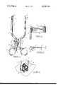
- FIG. 1is a plan view of the retractor of the invention
- FIG. 2is a side view of the upper end of the instrument
- FIG. 3is an end view of the plate and rod member in a closed position
- FIG. 4is a top view illustrating the disposition of retractor components in use to spread the sides of an incision.
- FIG. 1shows a retractor 10 of the invention for use by a right handed surgeon. It is to be understood that a left hand instrument will have the same features but will be a mirror image of that shown and described.
- the retractorcomprises a pair of movable handles 33 and 34 both secured to a common pivot pin 32 which extends through a slot in each of the handles. Thus, the handles are hinged on the pin.
- At the lower ends of the handlesare rings 35 and 36 through which a surgeon or operator may place a thumb and finger for selectively spreading or contracting the handles which concomitantly results in opposite movement of jaw-like arms 12 and 18. Since arm 12 is attached to handle 34 and arm 18 to handle 33, when the handles are contracted, this will cause the arms to be spread, opened or expanded and visa versa.
- an arc shaped rack or ratchet member 40 having a plurality of teeth or notches 42is attached to handle 34.
- the rackextends through slot 39 in handle 33 so that as handle 34 is moved relative to handle 33, the rack moves freely in slot 39.
- a pawl member 44also having a plurality of teeth preferably at least four, for mating with those of the rack is pivotally secured on handle 33 by pin 46 which extends through the handle and pawl.
- a flattened projection or flange 48provides a surface against which the operator may press to rotate the pawl thereby disengaging the pawl teeth from those of the rack.
- the pawlwill also include a projection or knob 43 which extends through the other end of slot 39 in arm 33.
- a leaf spring 45is attached at one end by rivet or screw 41 to arm 33 and abuts pawl projection 43 thereby biasing the pawl in the upward position for engagement or mesh of its teeth with those of rack 40.
- the pawlWith the pawl normally biased upwardly and urged against the rack to set the arm spread until the operator depresses flange 48 disengaging it from the rack thereby allowing movement of the handles.
- the teeth in the rackare slanted so that the handles may be moved toward one another thereby spreading the arms without requiring depression of tab 48 but not visa versa, i.e., spreading of the handles first requires depression of the finger tab to disengage the pawl teeth from the rack.
- the depth of the teeth in both the rack and pawlare about 3mm deep or more in order to give greater stability and reduce the risk of slippage once the retractor has been expanded in the incision during surgery.
- FIG. 1illustrates the retractor 10 from the underside, the device shown normally to be used by a right handed surgeon whereby plate 20 and rod 14 extend into the incision with the plate nearest the surgeon with the handles being operated by the surgeon's non-dominant or left hand.
- the surgeonwill work into the surgical area with his right hand between plate 20 and rod 14, the handles of the instrument being directed away from the surgeon's right hand.
- Plate 20is rather thin in cross-section and terminates in a toothed end surface 26 which teeth extend substantially along the botom plate edge.
- the plateextends downwardly when both arms 12 and 18 lie along a horizontal plane as the instrument is used as illustrated in FIG. 3.
- plate 20is secured along the upper end of arm 18 at a side edge opposite the toothed end 22 and comprises an angled portion 15 directed inwardly toward rod 14, a straight portion 22 which lies approximately parallel to rod 14, and an end portion 23 angled outwardly away from rod 14 and along the edge of which are located the teeth.
- the overall length of plate 20is at least five cm and preferably between 5 and about 9 cm and the width about 2 cm or less to about 1 cm.
- the length of angled portion 15 of plate 20is preferably between about 0.5 and 2.5 cm and more preferably 1 to 2 cm so that the distance B between the inner plate edge and the end at arm 18 is about 1 1 cm.
- this one cm plate anglewill allow the surgeon to insert an instrument such as forceps into the incision 40 over the upper side or arm 18 which is seen to be held away from the inner edge of the incision when the retractor is open as shown.
- the angle of plate portion 15 relative to plate portion 22will preferably be between about 20° and about 45°, the specific angle being within this range to achieve the 1 cm distance B.
- the specific angle of end portion 23is preferably between about 25° and 45°, sufficient to expose teeth 26 for properly gripping the flesh in the incision to stabilize the instrument.
- the other or opposite arm 12is secured at its lower end and is integral with handle 34.
- the major portion of arm 12is elongated and extends substantially straight up to its terminal end 28 to which rod or extension portion 14 is connected.
- the upper end 28 of arm 12preferably extends to at least a length equivalent to and across from the mid point or center of the width of plate 20 and more preferably extends to a distance across from the upper edge 24 of plate 20 as illustrated.
- Rod 14extends normal to the arm and substantially parallel with plate 20 and also angles downwardly from the upper arm end so that it terminates in a pointed projection 16 at approximately the mid point or center of plate 20.
- the length of the rodis preferably between about two-thirds and the full length of plate 20 so that pointed projection 16 is at about the center of the plate width and at least two-thirds of its length.
- the length of rod 14is preferably between about 3 and about 8 cm, again, depending on the length of plate 20 and terminating at about two-thirds of the plate length.
- rod lengthwill be about 3.3 cm as shown to approximate scale in FIGS. 2 and 3.
- the rod lengthis important to prevent hook or projection 16 from being driven into the neural canal as it would if the rod was substantially longer, approaching the length of plate 20.
- rod 14is too short, the projection would simply rest on bone, thereby often producing torque forces which would minimize the stability of the instrument.
- FIG. 4the plate and rod extending into incision 40.
- Handles 33 and 34(FIG. 1) are brought together as needed to spread arms 12 and 18 and open incision to the desired extend.
- the unique features of the instrumentmake it especially useful for microsurgical techniques, where maximum utilization of small incisions as well as field of view are absolute requirements for success in these procedures.
- the device shownis for use by a right handed surgeon in a micro lumbar discectomy, with the plate being on the right side of the patient (face down) and the surgeon working from the right side of the patient. With the plate and rod extending into the incision, the instrument handles are directed to the surgeon's left. An instrument for use by a left handed surgeon will be a mirror image of that shown.
- Other modifications within the purview of the invention to achieve the advantages thereofwill be evident to those skilled in the art.
Landscapes
- Health & Medical Sciences (AREA)
- Life Sciences & Earth Sciences (AREA)
- Surgery (AREA)
- Heart & Thoracic Surgery (AREA)
- Engineering & Computer Science (AREA)
- Biomedical Technology (AREA)
- Nuclear Medicine, Radiotherapy & Molecular Imaging (AREA)
- Medical Informatics (AREA)
- Molecular Biology (AREA)
- Animal Behavior & Ethology (AREA)
- General Health & Medical Sciences (AREA)
- Public Health (AREA)
- Veterinary Medicine (AREA)
- Surgical Instruments (AREA)
Abstract
Description
Claims (9)
Priority Applications (1)
| Application Number | Priority Date | Filing Date | Title |
|---|---|---|---|
| US05/601,059US4034746A (en) | 1975-08-01 | 1975-08-01 | Retractor |
Applications Claiming Priority (1)
| Application Number | Priority Date | Filing Date | Title |
|---|---|---|---|
| US05/601,059US4034746A (en) | 1975-08-01 | 1975-08-01 | Retractor |
Publications (1)
| Publication Number | Publication Date |
|---|---|
| US4034746Atrue US4034746A (en) | 1977-07-12 |
Family
ID=24406070
Family Applications (1)
| Application Number | Title | Priority Date | Filing Date |
|---|---|---|---|
| US05/601,059Expired - LifetimeUS4034746A (en) | 1975-08-01 | 1975-08-01 | Retractor |
Country Status (1)
| Country | Link |
|---|---|
| US (1) | US4034746A (en) |
Cited By (57)
| Publication number | Priority date | Publication date | Assignee | Title |
|---|---|---|---|---|
| US4693250A (en)* | 1986-01-29 | 1987-09-15 | Cook, Incorporated | Method for dilating puncture site in the renal pelvis |
| US4754746A (en)* | 1986-09-25 | 1988-07-05 | Cox Kenneth L | Self-retaining metatarsal spreader |
| US4932395A (en)* | 1988-05-18 | 1990-06-12 | Mehdizadeh Hamid M | Hemi-laminectomy retractor attachment device |
| USD314825S (en) | 1989-03-31 | 1991-02-19 | Torre Randall J | Skin retractor |
| US4997432A (en)* | 1988-03-23 | 1991-03-05 | Waldemar Link Gmbh & Co. | Surgical instrument set |
| US5019081A (en)* | 1986-12-10 | 1991-05-28 | Watanabe Robert S | Laminectomy surgical process |
| USD319877S (en) | 1989-01-12 | 1991-09-10 | R. Martin Oliveras | Gynecological forceps |
| FR2670109A1 (en)* | 1990-10-15 | 1992-06-12 | Lacaffiniere Jean Yves De | Total trapeziometacarpal prosthesis with intermediate component |
| US5176129A (en)* | 1991-03-01 | 1993-01-05 | Tekdyne, Inc. | Self-retaining refractor |
| US5599279A (en)* | 1994-03-16 | 1997-02-04 | Gus J. Slotman | Surgical instruments and method useful for endoscopic spinal procedures |
| US5613971A (en)* | 1995-08-11 | 1997-03-25 | Depuy Inc. | Ratcheting tibial and femoral guide |
| US5620458A (en)* | 1994-03-16 | 1997-04-15 | United States Surgical Corporation | Surgical instruments useful for endoscopic spinal procedures |
| US6074344A (en)* | 1999-07-14 | 2000-06-13 | Paschall, Jr.; Jack | Grasping retractor |
| US6196969B1 (en) | 1999-05-21 | 2001-03-06 | Lab Engineering & Manufacturing, Inc. | Tissue retractor adapted for the attachment of an auxiliary element |
| USD457956S1 (en) | 2001-05-18 | 2002-05-28 | Tibor B. Koros | Retractor |
| US20030055503A1 (en)* | 2001-09-19 | 2003-03-20 | O'neil Michael J. | Alignment verification device and method of use |
| US20030167059A1 (en)* | 2002-03-04 | 2003-09-04 | Young John Stewart | Devices and methods for spinal compression and distraction |
| US6652533B2 (en) | 2001-09-20 | 2003-11-25 | Depuy Acromed, Inc. | Medical inserter tool with slaphammer |
| US6709439B2 (en) | 2001-10-30 | 2004-03-23 | Depuy Spine, Inc. | Slaphammer tool |
| US6755841B2 (en) | 2000-05-08 | 2004-06-29 | Depuy Acromed, Inc. | Medical installation tool |
| US20040147935A1 (en)* | 2003-01-25 | 2004-07-29 | Christopher Segler | Tarsal Joint Space Distractor |
| US20050021042A1 (en)* | 2003-07-21 | 2005-01-27 | Theirry Marnay | Instruments and method for inserting an intervertebral implant |
| US20050027170A1 (en)* | 2003-07-10 | 2005-02-03 | Showa Ika Kohgyo Co., Ltd. | Surgical retractors |
| US20050080320A1 (en)* | 2003-08-14 | 2005-04-14 | Lee Andrew Max | Multiple-blade retractor |
| US20060195087A1 (en)* | 2005-02-02 | 2006-08-31 | Ronald Sacher | Adjustable length implant |
| US20060195088A1 (en)* | 2005-02-02 | 2006-08-31 | Ronald Sacher | Adjustable length implant |
| US20060235391A1 (en)* | 2005-03-08 | 2006-10-19 | Sutterlin Chester Iii | Facet joint stabilization |
| US20070016221A1 (en)* | 1999-09-14 | 2007-01-18 | Boris Beyersdorff | Insertion instrument for an intervertebral implant |
| US20070123903A1 (en)* | 2005-10-31 | 2007-05-31 | Depuy Spine, Inc. | Medical Device installation tool and methods of use |
| US20070162134A1 (en)* | 2002-12-13 | 2007-07-12 | Theirry Marnay | Intervertebral implant, insertion tool and method of inserting same |
| US20070185375A1 (en)* | 2006-02-06 | 2007-08-09 | Depuy Spine, Inc. | Medical device installation tool |
| US20070208346A1 (en)* | 2003-04-28 | 2007-09-06 | Theirry Marnay | Instruments and method for preparing an intervertebral space for receiving an artificial disc implant |
| US20080027436A1 (en)* | 2006-07-14 | 2008-01-31 | John Cournoyer | Rod to Rod Connectors and Methods of Adjusting The Length Of A Spinal Rod Construct |
| US20080177275A1 (en)* | 2006-12-01 | 2008-07-24 | Charles Wing | Interbody distractor |
| US20100168860A1 (en)* | 2008-12-22 | 2010-07-01 | Marc Reichen | Orthopedic implant with flexible keel |
| USD642679S1 (en)* | 2010-10-06 | 2011-08-02 | Raven Iii Raymond B | Surgical retractor |
| US20110307061A1 (en)* | 2010-06-15 | 2011-12-15 | Zyga Technology, Inc. | Systems and methods for facet joint treatment |
| US20120101505A1 (en)* | 2010-10-26 | 2012-04-26 | Zimmer, Inc. | Patellar resection instrument with variable depth guide |
| CN102715927A (en)* | 2012-07-07 | 2012-10-10 | 苏州市康力骨科器械有限公司 | Minimal invasive opening forceps |
| US8337500B2 (en) | 2006-07-31 | 2012-12-25 | Synthes Usa, Llc | Drilling/milling guide and keel cut preparation system |
| US20130072939A1 (en)* | 2007-05-17 | 2013-03-21 | Michael T. Gauthier | Compessor Distractor Tool |
| US8506634B2 (en) | 1999-07-02 | 2013-08-13 | DePuy Synthes Products, LLC | Intervertebral implant |
| US8998990B2 (en) | 2006-07-24 | 2015-04-07 | DePuy Synthes Products, LLC | Intervertebral implant with keel |
| US9233006B2 (en) | 2010-06-15 | 2016-01-12 | Zyga Technology, Inc. | Systems and methods for facet joint treatment |
| US20170273550A1 (en)* | 2016-03-28 | 2017-09-28 | Megaforce Company Limited | Expander |
| US9833328B2 (en) | 2010-06-15 | 2017-12-05 | Zyga Technology | System and methods for facet joint treatment |
| US20180103941A1 (en)* | 2016-10-13 | 2018-04-19 | Agha Khan | Surgical retractor |
| US20190090902A1 (en)* | 2013-03-14 | 2019-03-28 | Prescient Surgical, Inc. | Methods and devices for the prevention of incisional surgical site infections |
| WO2021015819A1 (en)* | 2019-07-25 | 2021-01-28 | Neuroenterprises Llc | Multipurpose surgical retractor and methods of use |
| US11224415B1 (en) | 2020-07-10 | 2022-01-18 | Warsaw Orthopedic, Inc. | Tissue retractor |
| USD951447S1 (en) | 2018-12-08 | 2022-05-10 | Gauthier Biomedical, Inc. | Handle |
| US11596439B2 (en) | 2017-11-07 | 2023-03-07 | Prescient Surgical, Inc. | Methods and apparatus for prevention of surgical site infection |
| US11607208B2 (en)* | 2018-08-09 | 2023-03-21 | Joshua Gilbert Kent | Tissue securing device and method of use |
| US12096923B2 (en) | 2020-07-10 | 2024-09-24 | Warsaw Orthopedic, Inc. | Tissue retractor, retraction modules, and associated methods |
| US20250114134A1 (en)* | 2023-10-05 | 2025-04-10 | Shukla Medical | Arthroscopic washer extractor |
| US12349889B2 (en) | 2020-07-10 | 2025-07-08 | Warsaw Orthopedic, Inc. | Tissue retractor, retraction modules, and associated methods |
| US12383249B2 (en) | 2020-07-10 | 2025-08-12 | Warsaw Orthopedic, Inc. | Tissue retractor, retraction modules, and associated methods |
Citations (4)
| Publication number | Priority date | Publication date | Assignee | Title |
|---|---|---|---|---|
| SU275298A1 (en)* | ||||
| FR511203A (en)* | 1920-03-08 | 1920-12-20 | Lucas Rojas Pineiro | New surgical instrument |
| US3038467A (en)* | 1960-08-29 | 1962-06-12 | Sklar Mfg Co J | Surgical instrument |
| US3470872A (en)* | 1966-11-25 | 1969-10-07 | Herman R Grieshaber | Pivoted retractor with shielded spacer teeth |
- 1975
- 1975-08-01USUS05/601,059patent/US4034746A/ennot_activeExpired - Lifetime
Patent Citations (4)
| Publication number | Priority date | Publication date | Assignee | Title |
|---|---|---|---|---|
| SU275298A1 (en)* | ||||
| FR511203A (en)* | 1920-03-08 | 1920-12-20 | Lucas Rojas Pineiro | New surgical instrument |
| US3038467A (en)* | 1960-08-29 | 1962-06-12 | Sklar Mfg Co J | Surgical instrument |
| US3470872A (en)* | 1966-11-25 | 1969-10-07 | Herman R Grieshaber | Pivoted retractor with shielded spacer teeth |
Cited By (102)
| Publication number | Priority date | Publication date | Assignee | Title |
|---|---|---|---|---|
| US4693250A (en)* | 1986-01-29 | 1987-09-15 | Cook, Incorporated | Method for dilating puncture site in the renal pelvis |
| US4754746A (en)* | 1986-09-25 | 1988-07-05 | Cox Kenneth L | Self-retaining metatarsal spreader |
| US5019081A (en)* | 1986-12-10 | 1991-05-28 | Watanabe Robert S | Laminectomy surgical process |
| US4997432A (en)* | 1988-03-23 | 1991-03-05 | Waldemar Link Gmbh & Co. | Surgical instrument set |
| US4932395A (en)* | 1988-05-18 | 1990-06-12 | Mehdizadeh Hamid M | Hemi-laminectomy retractor attachment device |
| USD319877S (en) | 1989-01-12 | 1991-09-10 | R. Martin Oliveras | Gynecological forceps |
| USD314825S (en) | 1989-03-31 | 1991-02-19 | Torre Randall J | Skin retractor |
| FR2670109A1 (en)* | 1990-10-15 | 1992-06-12 | Lacaffiniere Jean Yves De | Total trapeziometacarpal prosthesis with intermediate component |
| US5176129A (en)* | 1991-03-01 | 1993-01-05 | Tekdyne, Inc. | Self-retaining refractor |
| US5599279A (en)* | 1994-03-16 | 1997-02-04 | Gus J. Slotman | Surgical instruments and method useful for endoscopic spinal procedures |
| US5755732A (en)* | 1994-03-16 | 1998-05-26 | United States Surgical Corporation | Surgical instruments useful for endoscopic spinal procedures |
| US5620458A (en)* | 1994-03-16 | 1997-04-15 | United States Surgical Corporation | Surgical instruments useful for endoscopic spinal procedures |
| US5697889A (en)* | 1994-03-16 | 1997-12-16 | Gus J. Slotman | Surgical instruments useful for endoscopic spinal procedures |
| US5613971A (en)* | 1995-08-11 | 1997-03-25 | Depuy Inc. | Ratcheting tibial and femoral guide |
| US6196969B1 (en) | 1999-05-21 | 2001-03-06 | Lab Engineering & Manufacturing, Inc. | Tissue retractor adapted for the attachment of an auxiliary element |
| US8506634B2 (en) | 1999-07-02 | 2013-08-13 | DePuy Synthes Products, LLC | Intervertebral implant |
| US8974530B2 (en) | 1999-07-02 | 2015-03-10 | DePuy Synthes Products, LLC | Intervertebral implant |
| US9526624B2 (en) | 1999-07-02 | 2016-12-27 | DePuy Synthes Products, Inc. | Intervertebral implant |
| US8795371B2 (en) | 1999-07-02 | 2014-08-05 | DePuy Synthes Products, LLC | Intervertebral implant |
| US8882839B2 (en) | 1999-07-02 | 2014-11-11 | DePuy Synthes Products, LLC | Intervertebral implant |
| US6074344A (en)* | 1999-07-14 | 2000-06-13 | Paschall, Jr.; Jack | Grasping retractor |
| US8876836B2 (en) | 1999-09-14 | 2014-11-04 | DePuy Synthes Products, LLC | Insertion instrument for an intervertebral implant |
| US8535326B2 (en) | 1999-09-14 | 2013-09-17 | DePuy Synthes Products, LLC | Insertion instrument for an intervertebral implant |
| US20070016221A1 (en)* | 1999-09-14 | 2007-01-18 | Boris Beyersdorff | Insertion instrument for an intervertebral implant |
| US6755841B2 (en) | 2000-05-08 | 2004-06-29 | Depuy Acromed, Inc. | Medical installation tool |
| USRE46410E1 (en) | 2000-05-08 | 2017-05-23 | DePuy Synthes Products, Inc. | Medical installation tool |
| USRE43317E1 (en) | 2000-05-08 | 2012-04-17 | Depuy Spine, Inc. | Medical installation tool |
| USRE45639E1 (en) | 2000-05-08 | 2015-08-04 | DePuy Synthes Products, Inc. | Medical installation tool |
| USRE44835E1 (en) | 2000-05-08 | 2014-04-08 | Depuy Synthes Products Llc | Medical installation tool |
| USD457956S1 (en) | 2001-05-18 | 2002-05-28 | Tibor B. Koros | Retractor |
| US20030055503A1 (en)* | 2001-09-19 | 2003-03-20 | O'neil Michael J. | Alignment verification device and method of use |
| US6652533B2 (en) | 2001-09-20 | 2003-11-25 | Depuy Acromed, Inc. | Medical inserter tool with slaphammer |
| US6709439B2 (en) | 2001-10-30 | 2004-03-23 | Depuy Spine, Inc. | Slaphammer tool |
| US7011658B2 (en)* | 2002-03-04 | 2006-03-14 | Sdgi Holdings, Inc. | Devices and methods for spinal compression and distraction |
| US20030167059A1 (en)* | 2002-03-04 | 2003-09-04 | Young John Stewart | Devices and methods for spinal compression and distraction |
| US20070162134A1 (en)* | 2002-12-13 | 2007-07-12 | Theirry Marnay | Intervertebral implant, insertion tool and method of inserting same |
| US8579978B2 (en) | 2002-12-13 | 2013-11-12 | DePuy Synthes Products, LLC | Intervertebral implant, insertion tool and method of inserting same |
| US9084682B2 (en) | 2002-12-13 | 2015-07-21 | DePuy Synthes Products, Inc. | Intervertebral implant, insertion tool and method of inserting same |
| US9585763B2 (en) | 2002-12-13 | 2017-03-07 | DePuy Synthes Products, Inc. | Intervertebral implant, insertion tool and method of inserting same |
| US9956086B2 (en) | 2002-12-13 | 2018-05-01 | Centinel Spine Llc | Intervertebral implant, insertion tool and method of inserting same |
| US8105381B2 (en) | 2002-12-13 | 2012-01-31 | Spine Solutions, Inc. | Intervertebral implant, insertion tool and method of inserting same |
| US7097647B2 (en) | 2003-01-25 | 2006-08-29 | Christopher Paige Segler | Tarsal joint space distractor |
| US20040147935A1 (en)* | 2003-01-25 | 2004-07-29 | Christopher Segler | Tarsal Joint Space Distractor |
| US20070208346A1 (en)* | 2003-04-28 | 2007-09-06 | Theirry Marnay | Instruments and method for preparing an intervertebral space for receiving an artificial disc implant |
| US8663229B2 (en) | 2003-04-28 | 2014-03-04 | DePuy Synthes Products, LLC | Instruments and method for preparing an intervertebral space for receiving an artificial disc implant |
| US10182831B2 (en) | 2003-04-28 | 2019-01-22 | Centinel Spine Llc | Instruments and method for preparing an intervertebral space for receiving an artificial disc implant |
| US20050027170A1 (en)* | 2003-07-10 | 2005-02-03 | Showa Ika Kohgyo Co., Ltd. | Surgical retractors |
| US20050021042A1 (en)* | 2003-07-21 | 2005-01-27 | Theirry Marnay | Instruments and method for inserting an intervertebral implant |
| US7803162B2 (en) | 2003-07-21 | 2010-09-28 | Spine Solutions, Inc. | Instruments and method for inserting an intervertebral implant |
| US8349017B2 (en) | 2003-07-21 | 2013-01-08 | Spine Solutions, Inc. | Instruments and method for inserting an intervertebral implant |
| US20050080320A1 (en)* | 2003-08-14 | 2005-04-14 | Lee Andrew Max | Multiple-blade retractor |
| US7481766B2 (en) | 2003-08-14 | 2009-01-27 | Synthes (U.S.A.) | Multiple-blade retractor |
| US20060195087A1 (en)* | 2005-02-02 | 2006-08-31 | Ronald Sacher | Adjustable length implant |
| US20060195088A1 (en)* | 2005-02-02 | 2006-08-31 | Ronald Sacher | Adjustable length implant |
| US7927357B2 (en) | 2005-02-02 | 2011-04-19 | Depuy Spine, Inc. | Adjustable length implant |
| US7942908B2 (en)* | 2005-02-02 | 2011-05-17 | Depuy Spine, Inc. | Adjustable length implant |
| US20060235391A1 (en)* | 2005-03-08 | 2006-10-19 | Sutterlin Chester Iii | Facet joint stabilization |
| US8696707B2 (en) | 2005-03-08 | 2014-04-15 | Zyga Technology, Inc. | Facet joint stabilization |
| US20070123903A1 (en)* | 2005-10-31 | 2007-05-31 | Depuy Spine, Inc. | Medical Device installation tool and methods of use |
| US20070185375A1 (en)* | 2006-02-06 | 2007-08-09 | Depuy Spine, Inc. | Medical device installation tool |
| US8377072B2 (en) | 2006-02-06 | 2013-02-19 | Depuy Spine, Inc. | Medical device installation tool |
| US20080027436A1 (en)* | 2006-07-14 | 2008-01-31 | John Cournoyer | Rod to Rod Connectors and Methods of Adjusting The Length Of A Spinal Rod Construct |
| US8475499B2 (en) | 2006-07-14 | 2013-07-02 | DePuy Synthes Products, LLC. | Rod to rod connectors and methods of adjusting the length of a spinal rod construct |
| US11690728B2 (en) | 2006-07-24 | 2023-07-04 | Centinel Spine, Llc | Intervertebral implant with keel |
| US8998990B2 (en) | 2006-07-24 | 2015-04-07 | DePuy Synthes Products, LLC | Intervertebral implant with keel |
| US10583014B2 (en) | 2006-07-24 | 2020-03-10 | Centinel Spine, Llc | Intervertebral implant with keel |
| US9387086B2 (en) | 2006-07-24 | 2016-07-12 | DePuy Synthes Products, Inc. | Intervertebral implant with keel |
| US9883950B2 (en) | 2006-07-24 | 2018-02-06 | Centinel Spine Llc | Intervertebral implant with keel |
| US8337500B2 (en) | 2006-07-31 | 2012-12-25 | Synthes Usa, Llc | Drilling/milling guide and keel cut preparation system |
| US9254139B2 (en) | 2006-07-31 | 2016-02-09 | DePuy Synthes Products, Inc. | Drilling/milling guide and keel cut preparation system |
| US9949746B2 (en) | 2006-07-31 | 2018-04-24 | Centinel Spine Llc | Drilling/milling guide and keel cut preparation system |
| US9717511B2 (en) | 2006-07-31 | 2017-08-01 | DePuy Synthes Products, Inc. | Drilling/milling guide and keel cut preparation system |
| US20080177275A1 (en)* | 2006-12-01 | 2008-07-24 | Charles Wing | Interbody distractor |
| US7896884B2 (en) | 2006-12-01 | 2011-03-01 | Aesculap, Inc. | Interbody distractor |
| US20130072939A1 (en)* | 2007-05-17 | 2013-03-21 | Michael T. Gauthier | Compessor Distractor Tool |
| US9107719B2 (en)* | 2007-05-17 | 2015-08-18 | Gauthier Biomedical, Inc. | Compressor distractor tool |
| US20100168860A1 (en)* | 2008-12-22 | 2010-07-01 | Marc Reichen | Orthopedic implant with flexible keel |
| US8425603B2 (en) | 2008-12-22 | 2013-04-23 | Synthes Usa, Llc | Orthopedic implant with flexible keel |
| US8663293B2 (en)* | 2010-06-15 | 2014-03-04 | Zyga Technology, Inc. | Systems and methods for facet joint treatment |
| US9233006B2 (en) | 2010-06-15 | 2016-01-12 | Zyga Technology, Inc. | Systems and methods for facet joint treatment |
| US9314277B2 (en) | 2010-06-15 | 2016-04-19 | Zyga Technology, Inc. | Systems and methods for facet joint treatment |
| US9833328B2 (en) | 2010-06-15 | 2017-12-05 | Zyga Technology | System and methods for facet joint treatment |
| US20110307061A1 (en)* | 2010-06-15 | 2011-12-15 | Zyga Technology, Inc. | Systems and methods for facet joint treatment |
| CN103237525A (en)* | 2010-06-15 | 2013-08-07 | 正格技术公司 | Systems for facet joint treatment |
| USD642679S1 (en)* | 2010-10-06 | 2011-08-02 | Raven Iii Raymond B | Surgical retractor |
| US20120101505A1 (en)* | 2010-10-26 | 2012-04-26 | Zimmer, Inc. | Patellar resection instrument with variable depth guide |
| US8747410B2 (en)* | 2010-10-26 | 2014-06-10 | Zimmer, Inc. | Patellar resection instrument with variable depth guide |
| CN102715927A (en)* | 2012-07-07 | 2012-10-10 | 苏州市康力骨科器械有限公司 | Minimal invasive opening forceps |
| US20190090902A1 (en)* | 2013-03-14 | 2019-03-28 | Prescient Surgical, Inc. | Methods and devices for the prevention of incisional surgical site infections |
| US20170273550A1 (en)* | 2016-03-28 | 2017-09-28 | Megaforce Company Limited | Expander |
| US10441260B2 (en)* | 2016-03-28 | 2019-10-15 | Megaforce Company Limited | Expander |
| US20180103941A1 (en)* | 2016-10-13 | 2018-04-19 | Agha Khan | Surgical retractor |
| US11596439B2 (en) | 2017-11-07 | 2023-03-07 | Prescient Surgical, Inc. | Methods and apparatus for prevention of surgical site infection |
| US11607208B2 (en)* | 2018-08-09 | 2023-03-21 | Joshua Gilbert Kent | Tissue securing device and method of use |
| USD951447S1 (en) | 2018-12-08 | 2022-05-10 | Gauthier Biomedical, Inc. | Handle |
| WO2021015819A1 (en)* | 2019-07-25 | 2021-01-28 | Neuroenterprises Llc | Multipurpose surgical retractor and methods of use |
| US20220151601A1 (en)* | 2019-07-25 | 2022-05-19 | Neuroenterprises Llc | Multipurpose surgical retractor and methods of use |
| US11224415B1 (en) | 2020-07-10 | 2022-01-18 | Warsaw Orthopedic, Inc. | Tissue retractor |
| US12096923B2 (en) | 2020-07-10 | 2024-09-24 | Warsaw Orthopedic, Inc. | Tissue retractor, retraction modules, and associated methods |
| US12349889B2 (en) | 2020-07-10 | 2025-07-08 | Warsaw Orthopedic, Inc. | Tissue retractor, retraction modules, and associated methods |
| US12383249B2 (en) | 2020-07-10 | 2025-08-12 | Warsaw Orthopedic, Inc. | Tissue retractor, retraction modules, and associated methods |
| US20250114134A1 (en)* | 2023-10-05 | 2025-04-10 | Shukla Medical | Arthroscopic washer extractor |
Similar Documents
| Publication | Publication Date | Title |
|---|---|---|
| US4034746A (en) | Retractor | |
| US5556416A (en) | Endoscopic instrument | |
| EP3892208B1 (en) | Surgical stapling device with adjustable dissecting tip | |
| US5681337A (en) | Bone shaver | |
| US5928263A (en) | Surgical instrument with flexible actuator and rigid actuator cover | |
| US5484441A (en) | Rongeur surgical instrument | |
| JP4242044B2 (en) | Curved laparoscope with arc-shaped part of two kinds of curvature | |
| US4887756A (en) | Surgical stapler providing variable degree of staple closure | |
| US5788630A (en) | Rib retractor | |
| US5219354A (en) | Dissecting-cum haemostapling scissors | |
| US5196023A (en) | Surgical needle holder and cutter for an endo-suture, endo-ligature or the like | |
| US6033425A (en) | Lifting rib retractor | |
| US5282817A (en) | Actuating handle for multipurpose surgical instrument | |
| US4043343A (en) | Forceps | |
| US6368271B1 (en) | Method for humerus retraction | |
| US5931778A (en) | Rib retractor | |
| US20100011541A1 (en) | Handle and forceps/tweezers and method and apparatus for designing the like | |
| US20110015685A1 (en) | Guide for spinal tools, implants, and devices | |
| US20020049460A1 (en) | Surgical cutting instrument having concative jaw tips | |
| JP7397248B2 (en) | ophthalmic surgical instruments | |
| EP1018954A1 (en) | Back biting surgical instrument | |
| US5833697A (en) | Suture needle holding surgical instrument | |
| US10413290B1 (en) | Combined needle holder scissors | |
| CN108403160B (en) | Surgical instrument with hollow trigger | |
| EP2192861B1 (en) | Surgical retractor |
Legal Events
| Date | Code | Title | Description |
|---|---|---|---|
| AS | Assignment | Owner name:INSTITUTE FOR SOCIAL AND SCIENTIFIC DEVELOPMENT TH Free format text:ASSIGNMENT OF ASSIGNORS INTEREST.;ASSIGNOR:SOLOMON, JACK D.;REEL/FRAME:004610/0320 Effective date:19860827 Owner name:INSTITUTE FOR SOCIAL AND SCIENTIFIC DEVELOPMENT TH Free format text:ASSIGNMENT OF ASSIGNORS INTEREST;ASSIGNOR:SOLOMON, JACK D.;REEL/FRAME:004610/0320 Effective date:19860827 | |
| AS | Assignment | Owner name:SOLOMON, JACK D. Free format text:ASSIGNMENT OF ASSIGNORS INTEREST.;ASSIGNOR:GAMING AND TECHNOLOGY, INC.;REEL/FRAME:004961/0028 Effective date:19870824 Owner name:SOLOMON, JACK D. Free format text:AGREEMENT,;ASSIGNOR:GAMING AND TECHNOLOGY, INC.;REEL/FRAME:004961/0002 Effective date:19851216 Owner name:SOLOMON, JACK D. Free format text:ASSIGNMENT OF ASSIGNORS INTEREST.;ASSIGNOR:GAMING AND TECHNOLOGY, INC., A CORP. OF NV;REEL/FRAME:005004/0788 Effective date:19880906 |