US4034744A - Ultrasonic scanning system with video recorder - Google Patents
Ultrasonic scanning system with video recorderDownload PDFInfo
- Publication number
- US4034744A US4034744AUS05/631,623US63162375AUS4034744AUS 4034744 AUS4034744 AUS 4034744AUS 63162375 AUS63162375 AUS 63162375AUS 4034744 AUS4034744 AUS 4034744A
- Authority
- US
- United States
- Prior art keywords
- scan
- sector
- ultrasonic
- display
- transducer
- Prior art date
- Legal status (The legal status is an assumption and is not a legal conclusion. Google has not performed a legal analysis and makes no representation as to the accuracy of the status listed.)
- Expired - Lifetime
Links
- 239000002131composite materialSubstances0.000claimsabstractdescription8
- 238000010894electron beam technologyMethods0.000claims4
- 230000000977initiatory effectEffects0.000claims1
- 210000001835visceraAnatomy0.000abstractdescription3
- 238000002604ultrasonographyMethods0.000description12
- 239000000523sampleSubstances0.000description8
- 238000000034methodMethods0.000description6
- 238000002592echocardiographyMethods0.000description5
- 230000033001locomotionEffects0.000description5
- 230000005540biological transmissionEffects0.000description4
- 230000001419dependent effectEffects0.000description3
- 230000001360synchronised effectEffects0.000description3
- 239000013078crystalSubstances0.000description2
- 238000010586diagramMethods0.000description2
- 239000012530fluidSubstances0.000description2
- OAICVXFJPJFONN-UHFFFAOYSA-NPhosphorusChemical compound[P]OAICVXFJPJFONN-UHFFFAOYSA-N0.000description1
- 208000027418Wounds and injuryDiseases0.000description1
- 230000003750conditioning effectEffects0.000description1
- 230000006378damageEffects0.000description1
- 208000014674injuryDiseases0.000description1
- 231100000957no side effectToxicity0.000description1
- 210000000056organAnatomy0.000description1
- 230000005855radiationEffects0.000description1
- 239000000565sealantSubstances0.000description1
- 230000003068static effectEffects0.000description1
- 239000000126substanceSubstances0.000description1
- 238000004148unit processMethods0.000description1
Images


Classifications
- A—HUMAN NECESSITIES
- A61—MEDICAL OR VETERINARY SCIENCE; HYGIENE
- A61B—DIAGNOSIS; SURGERY; IDENTIFICATION
- A61B8/00—Diagnosis using ultrasonic, sonic or infrasonic waves
- G—PHYSICS
- G01—MEASURING; TESTING
- G01N—INVESTIGATING OR ANALYSING MATERIALS BY DETERMINING THEIR CHEMICAL OR PHYSICAL PROPERTIES
- G01N29/00—Investigating or analysing materials by the use of ultrasonic, sonic or infrasonic waves; Visualisation of the interior of objects by transmitting ultrasonic or sonic waves through the object
- G01N29/04—Analysing solids
- G01N29/06—Visualisation of the interior, e.g. acoustic microscopy
- G—PHYSICS
- G01—MEASURING; TESTING
- G01S—RADIO DIRECTION-FINDING; RADIO NAVIGATION; DETERMINING DISTANCE OR VELOCITY BY USE OF RADIO WAVES; LOCATING OR PRESENCE-DETECTING BY USE OF THE REFLECTION OR RERADIATION OF RADIO WAVES; ANALOGOUS ARRANGEMENTS USING OTHER WAVES
- G01S15/00—Systems using the reflection or reradiation of acoustic waves, e.g. sonar systems
- G01S15/88—Sonar systems specially adapted for specific applications
- G01S15/89—Sonar systems specially adapted for specific applications for mapping or imaging
- G01S15/8906—Short-range imaging systems; Acoustic microscope systems using pulse-echo techniques
- G01S15/8934—Short-range imaging systems; Acoustic microscope systems using pulse-echo techniques using a dynamic transducer configuration
- G01S15/8938—Short-range imaging systems; Acoustic microscope systems using pulse-echo techniques using a dynamic transducer configuration using transducers mounted for mechanical movement in two dimensions
- G01S15/894—Short-range imaging systems; Acoustic microscope systems using pulse-echo techniques using a dynamic transducer configuration using transducers mounted for mechanical movement in two dimensions by rotation about a single axis
- G—PHYSICS
- G10—MUSICAL INSTRUMENTS; ACOUSTICS
- G10K—SOUND-PRODUCING DEVICES; METHODS OR DEVICES FOR PROTECTING AGAINST, OR FOR DAMPING, NOISE OR OTHER ACOUSTIC WAVES IN GENERAL; ACOUSTICS NOT OTHERWISE PROVIDED FOR
- G10K11/00—Methods or devices for transmitting, conducting or directing sound in general; Methods or devices for protecting against, or for damping, noise or other acoustic waves in general
- G10K11/18—Methods or devices for transmitting, conducting or directing sound
- G10K11/26—Sound-focusing or directing, e.g. scanning
- G10K11/35—Sound-focusing or directing, e.g. scanning using mechanical steering of transducers or their beams
- G10K11/352—Sound-focusing or directing, e.g. scanning using mechanical steering of transducers or their beams by moving the transducer
- G10K11/355—Arcuate movement
Definitions
- This inventionrelates generally to ultrasonic scanning systems for use in observing organs in the body and more particularly to an ultrasonic sector scanning system.
- the ultrasoundis transmitted in a beam including brief pulses each followed by a relatively long interval where no transmission occurs. During this interval the pulse energy is transmitted through the body. Whenever a pulse of energy strikes a boundary between two substances having different acoustic impedances, a portion of the energy is reflected, some of it returning as an echo to the source. The remaining portion of the original energy is available to produce additional echoes from deeper interfaces.
- the crystal which serves as the transducer converting electrical energy into sound pulsesreceives the echoes and generates an electrical signal. This signal is amplified, displayed as a static or dynamic pattern on a cathode ray tube. The relative positions of the interfaces are shown on the display.
- a particular type of scanner usedis a sector scanner since it has the ability to display a cross-sectional area of the human body.
- a sector scannergenerally comprises an ultrasonic transducer (a piezoelectric element) which is mounted and motor driven through a suitable mechanical arrangement.
- the drive arrangementmoves the transducer which is generally in the form of a flat circular object back and forth in an arc scanning motion.
- the transduceris pulsed with high voltage spikes at pulsed repetition rates in the order of 3000 Hz. These spikes cause the piezoelectric element to mechanically ring, thereby emitting high frequency sound waves.
- These ultrasonic wavesimpinge upon the structure within the body and, when difference of acoustic impedance exists, are partially reflected back to the transducer element.
- the transducer elementacts like a receiver and converts these mechanical vibrations to electrical energy. This energy is amplified and processed such that it can be displayed on a cathode ray tube.
- the mechanical driving arrangementnot only drives the probe but also provides an electrical output analogous to transducer position by the use of position sensing means such as a potentiometer which translates position information into electrical energy.
- the electrical signalis processed and utilized to create horizontal and vertical signals which, along with the returning ultrasonic impulses, are used to create an X-Y display on the cathode ray tube.
- the resultant imageis a representation of the internal organs of the body.
- Another prior art system which allows real time examination of internal organs of the body such as the heartemploys a catheter which has a rotating tip which carries a plurality of transducers.
- the transducersare selectively connected to a pulser to transmit ultrasonic pulses into the body and to receive echoes therefrom.
- the echo pulsesare processed and applied to a cathode ray tube whereby they provide sequential representations of the area at a rate which is dependent upon the speed of rotation of the transducers and with a resolution which is dependent upon the pulse rate.
- Field ratesare selected so that the display can be photographed with a movie camera, for example, 24 frames per second.
- a systemwhich includes at least one ultrasonic transducer adapted to receive electrical pulses and transmit an ultrasonic beam into the body and which receives reflected ultrasonic energy and generates an electrical signal. Means are provided for moving the transducer so that it periodically scans a predetermined sector in a predetermined time. Pulses are applied at a predetermined rate whereby the time and rate determines the number of lines scanned in each field.
- a video recording meansis connected to the scanning system and serves to record a composite signal of the scan field including information respecting the beginning of each scan line and scan field and the transducer output whereby when the recording is reproduced, processed and applied to display means, it provides a display which corresponds exactly to the original display.
- the systemalso includes means for providing a display as the information is recorded.
- FIG. 1is a block diagram of a system in accordance with the present invention.
- FIG. 2is a timing diagram showing the waveforms at various portions of the system of FIG. 1.
- FIG. 3is a perspective view of a scanning head suitable for use in the system of the present invention.
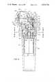
- FIG. 4is a sectional view of the scanning head partly broken away to show the interior components.
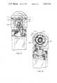
- FIGS. 5 and 6are sectional views taken along the lines 5--5 and 6--6 of FIG. 4 respectively.
- FIG. 7is a view of one side of the head portion partly broken away to show the interior components.
- FIG. 8is a view of the opposite side of the head partly broken away to show the interior components.
- the system describedincludes a rotor 11 driven by a motor 12.
- the rotor 11carries a plurality of ultrasonic transducers 13 spaced about the periphery of the rotor.
- the rotating member 11also carries a plurality of spaced reflecting surfaces 14 which are viewed by a phototransducer 16 which provides an output pulse as each reflective surface 14 passes the phototransducer.
- the output of the phototransducer 16is applied to motor control 17 to which is also applied a reference frequency along the line 18 from sync generator 19 which serves to synchronize the operation of the overall system as will be presently described.
- Input to the sync generatoris from a clock system 21 which may include a crystal together with appropriate dividers to provide a control frequency to the sync generator 19.
- the output on the line 18may, for example, be a 60 Hertz output which is applied to the motor control.
- the output pulses from the phototransducer 16are employed in a servo system to servo control operation of the motor 12 and to control the position of the rotor 11 whereby the position of the transducer is accurately determined as the rotor rotates.
- Ultrasonic pulsesare applied sequentially to the individual transducers at a high rate so that they scan a plurality of lines in a fan or sector as the member rotates. This is schematically shown in the Figure where the transducers 13 are shown with one side connected to a common input line 23 with the other side adapted to be connected to ground 24 as the rotor rotates. Consequently, only one of the transducers is connected during 90° of rotation.
- the arrangementis such that as one transducer scans a 90° sector, the next transducer begins to scan the same 90° sector in sequence.
- the sync generator 19applies trigger pulses along the line 26 to an interface 27 which drives a suitable transmitter and receiver 28.
- the transmitter-receivermay be an Ekoline 20A/B which serves to receive trigger pulses and transmit ultrasonic pulses for application to the transducer.
- the transducerreceives the echoes from the interfaces and the receiver processes the same and provides ultrasound data along the line 29 to the interface 27.
- the ultrasound dataappears on the line 30 and is applied to a data conditioning and composite video generator 31 and to a display data switch 32.
- the sync generator 19applies a sync pulse to the sweep generator 33 which serves to form a plurality of sawtooth voltage waves such as shown in FIG. 2C.
- the sawtooth voltage wavesprovide the so-called "R" sweep voltage which is modified as will be presently described.
- the sync generatoralso serves to generate a trigger pulse responsive to the output from the transducer 16 to thereby indicate the beginning of a sweep.
- This trigger pulseserves to form a sawtooth voltage such as shown in FIG. 2B which provides the ⁇ sweep voltage which is also modified.
- the number of linesis, therefore, directly dependent upon the frequency of the ultrasonic pulses which are applied to the transducers.
- the ultrasound data on the line 30is applied through the display switch to the monitor along the line 41 and serves to modulate the intensity of the beam whereby the scan will be modulated in accordance with the ultrasound data which is received as a result of reflections from the interfaces.
- the speed of rotation of the rotor 11determines the number of fields or displays which are available per second while the number of pulses applied determines the number of lines. It is apparent, however, that the pulse rate is limited by the depth which the scan must reach since there must be enough time between pulses to receive echoes from the deepest portion observed.
- the sync signals from the sync generator 19 corresponding both to the R and ⁇ sync signals applied to the sweep generatorsare also applied to a data conditioner 31.
- the data conditioneralso receives the ultrasound data.
- the unitprocesses the data in a manner similar to a television composite signal generator. It provides a composite video signal on the line 43.
- the signalis illustrated at Figure 2A and includes vertical sync pulses 51, horizontal sync pulses 52 and the ultrasound data 53 for each scan line.
- the video recordermay be any conventional video recorder such as a helical scan recorder which serves to record video signal.
- the rotation of the recording heads and the motion of the tapeis synchronized with the timing system of the ultrasonic scanning system whereby to provide the recording of sequential fields of information.
- the video recorder composite signalis applied along the line 53 to a data sync separator 54 which separates out the R and ⁇ sync pulses and applies them to the sweep generator 33 which provides the appropriate sweep signals through the multipliers 36 and 37 for driving the deflection circuits of the cathode ray tube.
- the separated ultrasound data on the line 57is applied to the display switch and directly to the video display in the same manner as the original ultrasound pulses to modulate the intensity.
- the playback displayis identical to the original display.
- the rate of rotation and the pulse rateare so selected that the scan lines are interlaced, that is, the scan lines for each sequential field are interlaced with the scan line of the previous field thereby giving a higher resolution without flicker.
- video tape recordersare based on a helical scanning principle.
- the video recording tapeis wrapped around a drum in which one or more record/playback heads are rotating. Each head protrudes through a slot which traverses the outer diameter of the drum.
- the tapeis wrapped almost parallel to the plane of the moving head so that the head moves at an angle with respect to the longitudinal axis of the tape, thus generating a helical scanning pattern.
- Two television fieldsare recorded on the tape every one-thirtieth of a second. These fields by themselves do not represent the entire television picture. These two fields are required to create a television frame.
- the two fieldsare scanned onto a cathode ray tube screen in an interlaced pattern to provide the frame.
- the first set of horizontal scan lines corresponding to one fieldis drawn on the phosphor screen, after which the second set corresponding to the other field is placed in the space between the first set of lines.
- This 2:1 interlacing techniqueprovides the viewer with a high resolution, twice the resolution of either field separately.
- the ultrasonic signals producedwill be recorded in the same field/frame format as would a television image.
- the cylindrical transducer headmakes a complete rotation in one-thirtieth of a second in 1:1 synchronism with the video tape recorder head, four fields per revolution are created if a four element head is chosen.
- Each fieldwould contain a number of lines which would be determined by the pulse repetition rate at which the elements are driven and the length of time each transducer is actively being pulsed. In the above case, is a pulse repetition rate of 3000 Hz is chosen, there would be 25 lines per field.
- a suitable systemwould be for a transducer element rotating at 900 rpm pulsed at 3000 Hz and utilizing a 4:1 interlace. This would give 50 lines per field and 200 lines per frame.
- the displaywould be a 90° segment with an apparent 200 line resolution.
- the interlacewould be lines 1, 3, 2, 4. This would provide minimum flicker since the maximum time difference between any two adjacent lines would be only two fields.
- the pulse repetition rate of the ultrasonoscope driving the rotating section transduceris synchronized with the rotating transducer head which is achieved by the sync generator in the present invention.
- the mechanical driving arrangement of the prior art sector scannerprovides an electrical output analogous to transducer position by use of a position sensing means. This electrical output is ultimately used to create the X-Y display on the cathode ray tube.
- the rotating sector transduceralso provides a position signal. This signal is recorded on the video tape recorder in the present method and provides the field synchronizing pulse.
- the position of the transducer element in each instant of timemust be available to the X-Y display processing circuitry simultaneously with the appropriate ultrasonic information. This is provided by the line pulses recorded for each scan line. Upon reproduction from the video tape recorder, the timing information is recovered to drive the sweep generators.
- the number of lines per fieldare chosen to include a fractional portion, that is, if there is to be a 4:1 interlace, the lines per field would be 49.25 to provide the suitable interlace.
- FIGS. 3 through 8A suitable rotating head assembly and probe for use in connection with the present invention is shown in FIGS. 3 through 8.
- the rotating head assembly and probeform the subject matter of copending application Ser. No. 631,456 filed Nov. 13, 1975.
- the probeincludes handle 61 which is detachably secured to a scanning head 62 by means of a ring 63 which engages threads 64 formed on the head 62 (FIG. 4).
- the attachment of the head 62 to the handle 61provides a mechanical connection to the driving motor and an electrical connection to associated equipment as will be presently described.
- the head 62includes the rotor 11 with a plurality of transducers 13 which rotate in a plane parallel to the axis of the probe handle.
- the handle 61serves to house the motor 12 with the motor shaft 64 attached to coupler 66.
- the couplerhas its forward end slotted with two crossing slots 67 as shown more particularly in FIG. 6.
- the slots 67are adapted to engage pin 68 mounted on driven shaft 69.
- the driven shaft 69is mounted for rotation by spaced bearings 71 and 72 mounted in the disc shaped mounting block 73.
- An O-ring seal 74serves to seal the shaft and prevent leakage of ultrasound transmitting fluid which fills the head portion as will be presently described.
- Opinion gear 76is mounted on the end of the shaft and engages bevel gear 77 mounted on the rotor shaft 78.
- rotation of the motorserves to rotate the rotor 11.
- the rotor 11is supported for rotation by a shaft 78 which is mounted on spaced bearings 79 and 81.
- the complete assembly just describedis housed within a shell or cover 82 which has a relatively thin portion 83 adjacent the probe face to thereby permit the transmission of ultrasonic energy.
- the complete interior of the housingis filled with a suitable fluid which provides continuity for the transmission of the ultrasonic energy from the transducers 13 to and through the window 83.
- the window 83is adapted to be placed against the body to be examined.
- the rotorincludes a plurality of reflective surfaces 14.
- the phototransducer 16cooperates with the surfaces and provides an output signal through a connector 84 to the cable 85 carried by the handle.
- the ultrasound pulsesare applied to the wires 23 through a coaxial connector 86 to the brush block 87 suitably attached to the mounting brackets 88 by screws 89.
- the brushes 91, 92 and 93ride within associated grooves formed on the extension of the shaft 78. Slip rings are carried in the grooves and are connected to leads which run coaxially within the hollow shaft 78 and exit at the opposite end of the rotor as will be presently described.
- the brush block and its mountingis more clearly shown in FIG. 7 and includes a pair of screws 89 attaching the brush block 87 to L-shaped support 88 which, in turn, are secured to the disc 73.
- the systemincludes a printed circuit board 101 suitably attached to the rotor as, for example, by pins 102, FIG. 4.
- the commutating systemincludes four commutating segments 103, each having one end 104 connected to an associated transducer and extending approximately 90°.
- the ultrasonic energyis directed coaxially through the shaft and connected to the continuous commutating ring 106.
- a brush 107serves to provide contact between the rings 106 and segments 103 whereby as the rotor is rotated, the ring 106 is sequentially connected to each of the segments 103 to sequentially connect one side of each of the transducers to the source of energy.
- each of the transducersis connected to a ring 105 which is, in turn, connected to ground to provide the other terminal for the transducers.
- the rotor housing 82includes a first portion 108 which is threaded and adapted to be engaged by the ring 63 and a second substantially hemispherical portion 109 adapted to be attached thereto so that the rotor and associated parts can be placed within a fluid-tight housing.
- the hemispherical portion 109is suitably secured to the portion 108 by means of screws 110 of FIG. 7.
- a suitable sealantis provided between the spherical portions and the intersecting surfaces of the portion 108.
- a compact, movable probewhich can be easily applied to the body for scanning particular section thereof.
- the head portionscan be removed and a new head inserted.
- a head having three or two transducersmay be employed in connection with the motor handle 61.
- the system described aboveoperates by synchronously recording on the recording medium the fields and lines scanned by the transducer with the motion of the recording head, it is possible to operate asynchronously. That is, the movement of the ultrasonic transducer need not by synchronous with the movement of the recording heads.
Landscapes
- Physics & Mathematics (AREA)
- Engineering & Computer Science (AREA)
- Health & Medical Sciences (AREA)
- Life Sciences & Earth Sciences (AREA)
- Acoustics & Sound (AREA)
- Remote Sensing (AREA)
- Radar, Positioning & Navigation (AREA)
- General Health & Medical Sciences (AREA)
- Pathology (AREA)
- General Physics & Mathematics (AREA)
- Nuclear Medicine, Radiotherapy & Molecular Imaging (AREA)
- Biophysics (AREA)
- Surgery (AREA)
- Animal Behavior & Ethology (AREA)
- Radiology & Medical Imaging (AREA)
- Public Health (AREA)
- Veterinary Medicine (AREA)
- Medical Informatics (AREA)
- Biomedical Technology (AREA)
- Molecular Biology (AREA)
- Computer Networks & Wireless Communication (AREA)
- Heart & Thoracic Surgery (AREA)
- Chemical & Material Sciences (AREA)
- Analytical Chemistry (AREA)
- Biochemistry (AREA)
- Immunology (AREA)
- Multimedia (AREA)
- Ultra Sonic Daignosis Equipment (AREA)
- Investigating Or Analyzing Materials By The Use Of Ultrasonic Waves (AREA)
Abstract
Description
Claims (12)
Priority Applications (7)
| Application Number | Priority Date | Filing Date | Title |
|---|---|---|---|
| US05/631,623US4034744A (en) | 1975-11-13 | 1975-11-13 | Ultrasonic scanning system with video recorder |
| GB46567/76AGB1550220A (en) | 1975-11-13 | 1976-11-09 | Ultrasonic scanning system and method |
| DE19762651461DE2651461A1 (en) | 1975-11-13 | 1976-11-11 | ULTRASONIC SCANNING DEVICE WITH VISUAL DISPLAY AND RECORDING |
| FR7634171AFR2331792A1 (en) | 1975-11-13 | 1976-11-12 | ULTRASONIC EXPLORATION DEVICE |
| CA265,555ACA1059232A (en) | 1975-11-13 | 1976-11-12 | Ultrasonic scanning system and method |
| JP51136172AJPS5275427A (en) | 1975-11-13 | 1976-11-12 | Ultrasonic wave scanning system |
| AU19638/76AAU490243B2 (en) | 1975-11-13 | 1976-11-15 | Ultrasonic scanning method and system |
Applications Claiming Priority (1)
| Application Number | Priority Date | Filing Date | Title |
|---|---|---|---|
| US05/631,623US4034744A (en) | 1975-11-13 | 1975-11-13 | Ultrasonic scanning system with video recorder |
Publications (1)
| Publication Number | Publication Date |
|---|---|
| US4034744Atrue US4034744A (en) | 1977-07-12 |
Family
ID=24532022
Family Applications (1)
| Application Number | Title | Priority Date | Filing Date |
|---|---|---|---|
| US05/631,623Expired - LifetimeUS4034744A (en) | 1975-11-13 | 1975-11-13 | Ultrasonic scanning system with video recorder |
Country Status (6)
| Country | Link |
|---|---|
| US (1) | US4034744A (en) |
| JP (1) | JPS5275427A (en) |
| CA (1) | CA1059232A (en) |
| DE (1) | DE2651461A1 (en) |
| FR (1) | FR2331792A1 (en) |
| GB (1) | GB1550220A (en) |
Cited By (67)
| Publication number | Priority date | Publication date | Assignee | Title |
|---|---|---|---|---|
| US4106492A (en)* | 1977-01-12 | 1978-08-15 | The United States Of America As Represented By The Secretary Of The Department Of Health, Education And Welfare | Real time two-dimensional mechanical ultrasonic sector scanner with electronic control of sector width |
| US4149419A (en)* | 1977-11-25 | 1979-04-17 | Smith Kline Instruments, Inc. | Ultrasonic transducer probe |
| US4151834A (en)* | 1976-09-30 | 1979-05-01 | Tokyo Shibaura Electric Co., Ltd. | Ultrasonic diagnostic apparatus |
| US4174705A (en)* | 1976-06-25 | 1979-11-20 | Siemens Aktiengesellschaft | Ultrasonic imaging apparatus operating according to the impulse-echo method |
| DE2822261A1 (en)* | 1978-05-22 | 1979-11-29 | Terrance Dr Matzuk | Servo-controlled ultrasonic scanning appts. - has permanent magnets and electromagnets for rotating transducer about axis of needle bearings |
| US4181120A (en)* | 1976-04-23 | 1980-01-01 | Tokyo Shibaura Electric Co., Ltd. | Vessel for ultrasonic scanner |
| US4228687A (en)* | 1978-03-31 | 1980-10-21 | Emi Limited | Ultrasonic transducers |
| US4233988A (en)* | 1978-07-05 | 1980-11-18 | Life Instruments Corporation | High resolution rotating head ultrasonic scanner |
| US4248090A (en)* | 1978-03-27 | 1981-02-03 | New York Institute Of Technology | Apparatus for ultrasonically imaging a body |
| EP0028325A1 (en)* | 1979-10-16 | 1981-05-13 | Siemens Aktiengesellschaft | Ultrasonic sector-scanning device |
| US4269066A (en)* | 1979-08-16 | 1981-05-26 | Fischer Christopher L | Ultrasonic sensing apparatus |
| US4271842A (en)* | 1978-03-03 | 1981-06-09 | Smith Kline Instruments, Inc. | Apparatus and method for providing multiple ultrasonic sector image displays |
| US4310853A (en)* | 1980-07-30 | 1982-01-12 | Technicare Corporation | Data simulation in sector scan imaging systems |
| US4375818A (en)* | 1979-03-12 | 1983-03-08 | Olympus Optical Company Ltd. | Ultrasonic diagnosis system assembled into endoscope |
| US4454763A (en)* | 1982-08-12 | 1984-06-19 | Washington Research Foundation | Rotary ultrasonic scan head including fluid drive |
| US4494549A (en)* | 1981-05-21 | 1985-01-22 | Olympus Optical Co., Ltd. | Device for diagnosing body cavity interiors with supersonic waves |
| US4494548A (en)* | 1982-04-20 | 1985-01-22 | Biosound, Inc. | Ultrasonic sector scanner |
| DE2857246C2 (en)* | 1977-12-12 | 1985-07-25 | Rca Corp., New York, N.Y. | Ultrasonic pulse echo imaging device |
| EP0157408A3 (en)* | 1984-04-02 | 1986-01-08 | Advanced Technology Laboratories, Inc. | Fully wetted mechanical ultrasound scanhead |
| US4572202A (en)* | 1983-11-14 | 1986-02-25 | Elscint Inc. | Method and apparatus for high-speed ultrasonic imaging |
| EP0176878A1 (en)* | 1984-09-25 | 1986-04-09 | Kontron Instruments Holding N.V. | Ultrasonic compound scanning with a rotating transducer |
| US4688576A (en)* | 1985-01-14 | 1987-08-25 | Technicare Corporation | Ultrasonic transducer probe assembly |
| DE3727212A1 (en)* | 1986-08-15 | 1988-02-25 | Olympus Optical Co | ULTRASONIC IMAGING DEVICE |
| EP0233724A3 (en)* | 1986-01-30 | 1988-08-31 | Matsushita Electric Industrial Co., Ltd. | Ultrasonic probe for medical diagnostic examination |
| US4802458A (en)* | 1984-03-09 | 1989-02-07 | Ethicon, Inc. | Dual function ultrasonic transducer probes |
| US4869258A (en)* | 1986-12-05 | 1989-09-26 | Siemens Aktiengesellschaft | Intracavitary ultrasound scanner means |
| EP0355175A1 (en)* | 1988-08-17 | 1990-02-28 | Siemens Aktiengesellschaft | Apparatus for the contactless disintegration of concrements in the body of a living being |
| US5131393A (en)* | 1990-06-25 | 1992-07-21 | Fuji Photo Optical Co., Ltd. | Ultrasound internal examination system |
| WO1996025099A1 (en)* | 1995-02-15 | 1996-08-22 | Ultra-Scan Corporation | Ultrasonic biometric imaging and identity verification system |
| US5797848A (en)* | 1997-01-31 | 1998-08-25 | Acuson Corporation | Ultrasonic transducer assembly with improved electrical interface |
| US5902245A (en)* | 1986-02-28 | 1999-05-11 | Cardiovascular Imaging Systems, Inc. | Method and apparatus for intravascular ultrasonography |
| US6004273A (en)* | 1997-09-22 | 1999-12-21 | Fuji Photo Optical Co., Ltd. | Ultrasound transmission medium feed device for endoscopically inserting ultrasound probe |
| US6017311A (en)* | 1997-09-24 | 2000-01-25 | Fuji Photo Optical Co., Ltd. | Ultrasound probe having an insulating sleeve member |
| US6039695A (en)* | 1997-07-24 | 2000-03-21 | Fuji Photo Optical Co., Ltd. | Probe coupler for ultrasound examination system |
| US20030125758A1 (en)* | 2000-12-20 | 2003-07-03 | Fox Hollow Technologies, Inc. | Debulking catheters and methods |
| US20040122319A1 (en)* | 2002-10-10 | 2004-06-24 | Mehi James I. | High frequency, high frame-rate ultrasound imaging system |
| US20050197572A1 (en)* | 2004-03-01 | 2005-09-08 | Ross Williams | System and method for ECG-triggered retrospective color flow ultrasound imaging |
| US20060195126A1 (en)* | 1999-08-19 | 2006-08-31 | Fox Hollow Technologies, Inc., A Corporation Of Delaware | Atherectomy catheter with aligned imager |
| US20070010840A1 (en)* | 2003-04-22 | 2007-01-11 | Fox Hollow Technologies, Inc. | Methods and devices for cutting tissue at a vascular location |
| US20070276419A1 (en)* | 2006-05-26 | 2007-11-29 | Fox Hollow Technologies, Inc. | Methods and devices for rotating an active element and an energy emitter on a catheter |
| US20080065125A1 (en)* | 2000-12-20 | 2008-03-13 | Foxhollow Technologies, Inc. | High capacity debulking catheter with distal driven cutting wheel |
| US20090187203A1 (en)* | 1999-08-19 | 2009-07-23 | Fox Hollow Technologies, Inc. | Apparatus and methods for material capture and removal |
| US20090299394A1 (en)* | 1999-08-19 | 2009-12-03 | Fox Hollow Technologies, Inc. | Methods and devices for cutting tissue |
| US20100130996A1 (en)* | 2008-10-13 | 2010-05-27 | Fox Hollow Technologies, Inc. | Devices and methods for manipulating a catheter shaft |
| US20100198240A1 (en)* | 2000-12-20 | 2010-08-05 | Fox Hollow Technologies, Inc. | Debulking catheters and methods |
| US20100292721A1 (en)* | 2009-05-14 | 2010-11-18 | Fox Hollow Technologies, Inc. | Easily cleaned atherectomy catheters and methods of use |
| US20110130777A1 (en)* | 2009-12-02 | 2011-06-02 | Fox Hollow Technologies, Inc. | Methods and devices for cutting tissue |
| US20110144673A1 (en)* | 2009-12-11 | 2011-06-16 | Fox Hollow Technologies, Inc. | Material removal device having improved material capture efficiency and methods of use |
| US20120227473A1 (en)* | 2010-09-03 | 2012-09-13 | Los Alamos National Security, Llc | Apparatus and method for visualization of particles suspended in a fluid and fluid flow patterns using ultrasound |
| US8328829B2 (en) | 1999-08-19 | 2012-12-11 | Covidien Lp | High capacity debulking catheter with razor edge cutting window |
| US8784440B2 (en) | 2008-02-25 | 2014-07-22 | Covidien Lp | Methods and devices for cutting tissue |
| US8808186B2 (en) | 2010-11-11 | 2014-08-19 | Covidien Lp | Flexible debulking catheters with imaging and methods of use and manufacture |
| US8920450B2 (en) | 2010-10-28 | 2014-12-30 | Covidien Lp | Material removal device and method of use |
| US8992717B2 (en) | 2011-09-01 | 2015-03-31 | Covidien Lp | Catheter with helical drive shaft and methods of manufacture |
| US9119662B2 (en) | 2010-06-14 | 2015-09-01 | Covidien Lp | Material removal device and method of use |
| US20150374337A1 (en)* | 2013-03-06 | 2015-12-31 | Kabushiki Kaisha Toshiba | Ultrasound diagnostic apparatus |
| US9532844B2 (en) | 2012-09-13 | 2017-01-03 | Covidien Lp | Cleaning device for medical instrument and method of use |
| US9687266B2 (en) | 2009-04-29 | 2017-06-27 | Covidien Lp | Methods and devices for cutting and abrading tissue |
| US9943329B2 (en) | 2012-11-08 | 2018-04-17 | Covidien Lp | Tissue-removing catheter with rotatable cutter |
| CN108618806A (en)* | 2017-03-16 | 2018-10-09 | 柯尼卡美能达株式会社 | Ultrasonic detector and diagnostic ultrasound equipment |
| US10213224B2 (en) | 2014-06-27 | 2019-02-26 | Covidien Lp | Cleaning device for catheter and catheter including the same |
| US10292721B2 (en) | 2015-07-20 | 2019-05-21 | Covidien Lp | Tissue-removing catheter including movable distal tip |
| US10314667B2 (en) | 2015-03-25 | 2019-06-11 | Covidien Lp | Cleaning device for cleaning medical instrument |
| US10314664B2 (en) | 2015-10-07 | 2019-06-11 | Covidien Lp | Tissue-removing catheter and tissue-removing element with depth stop |
| US10945706B2 (en) | 2017-05-05 | 2021-03-16 | Biim Ultrasound As | Hand held ultrasound probe |
| US11564656B2 (en)* | 2018-03-13 | 2023-01-31 | Verathon Inc. | Generalized interlaced scanning with an ultrasound probe |
| FR3142339A1 (en) | 2022-11-30 | 2024-05-31 | Echopen Factory | VERSATILE ULTRASOUND PROBE WITH MULTIPLE SINGLE-ELEMENT TRANSDUCERS WITH OSCILLATING MECHANICAL SCANNING |
Families Citing this family (14)
| Publication number | Priority date | Publication date | Assignee | Title |
|---|---|---|---|---|
| FI62950C (en)* | 1978-03-27 | 1983-04-11 | New York Inst Techn | UNDERSOEKNINGSMODUL TILL EN ULTRALJUDSAVBILDNINGSANORDNING |
| JPS55120851A (en)* | 1979-03-12 | 1980-09-17 | Olympus Optical Co | Ultrasonic wave diagnosis device for inside of coelom |
| JPS5631743A (en)* | 1979-08-23 | 1981-03-31 | Olympus Optical Co | Ultrasonic scanner for inspecting inside of coelom |
| JPS5660547A (en)* | 1979-10-24 | 1981-05-25 | Olympus Optical Co | Ultrasonic picture projector |
| JPS5660546A (en)* | 1979-10-24 | 1981-05-25 | Olympus Optical Co | Ultrasonic picture projector |
| JPS5737442A (en)* | 1980-08-20 | 1982-03-01 | Fujitsu Ltd | Ultrasonic diagnostic apparatus |
| JPS627301Y2 (en)* | 1980-10-28 | 1987-02-20 | ||
| NL8102104A (en)* | 1981-04-29 | 1982-11-16 | Philips Nv | DEVICE FOR EXAMINATION USING ULTRA-SOUND WAVES. |
| US4402223A (en)* | 1981-08-07 | 1983-09-06 | General Electric Company | Ultrasonic sector scanner utilizing rotating transducer |
| US4453409A (en)* | 1981-08-07 | 1984-06-12 | General Electric Company | Ultrasonic sector scanner utilizing rotating transducer |
| JPS5893863U (en)* | 1981-12-18 | 1983-06-25 | 株式会社トキメック | rotary probe |
| JPH066122B2 (en)* | 1984-09-21 | 1994-01-26 | 松下電器産業株式会社 | Ultrasonic probe |
| JPS62133602U (en)* | 1986-02-18 | 1987-08-22 | ||
| JPS6316006U (en)* | 1986-07-16 | 1988-02-02 |
Citations (6)
| Publication number | Priority date | Publication date | Assignee | Title |
|---|---|---|---|---|
| US3547101A (en)* | 1967-05-24 | 1970-12-15 | Magnaflux Corp | Medical ultrasonic diagnostic system |
| US3690311A (en)* | 1971-05-27 | 1972-09-12 | Zenith Radio Corp | Ultrasonic scanning apparatus with transducer scanning rate-responsive transmitter |
| US3778756A (en)* | 1972-09-01 | 1973-12-11 | Gen Electric | Method and apparatus for visual imaging of ultrasonic echo signals utilizing a single transmitter |
| US3779234A (en)* | 1971-06-30 | 1973-12-18 | Intersc Res Inst | Ultrasonic catheter with rotating transducers |
| US3817089A (en)* | 1971-06-30 | 1974-06-18 | Interscience Res Inst | Rotating probe high data acquistion rate apparatus |
| US3828609A (en)* | 1972-09-05 | 1974-08-13 | Automation Ind Inc | Tube inspection system with interlaced scanning |
- 1975
- 1975-11-13USUS05/631,623patent/US4034744A/ennot_activeExpired - Lifetime
- 1976
- 1976-11-09GBGB46567/76Apatent/GB1550220A/ennot_activeExpired
- 1976-11-11DEDE19762651461patent/DE2651461A1/ennot_activeWithdrawn
- 1976-11-12FRFR7634171Apatent/FR2331792A1/enactiveGranted
- 1976-11-12JPJP51136172Apatent/JPS5275427A/enactivePending
- 1976-11-12CACA265,555Apatent/CA1059232A/ennot_activeExpired
Patent Citations (6)
| Publication number | Priority date | Publication date | Assignee | Title |
|---|---|---|---|---|
| US3547101A (en)* | 1967-05-24 | 1970-12-15 | Magnaflux Corp | Medical ultrasonic diagnostic system |
| US3690311A (en)* | 1971-05-27 | 1972-09-12 | Zenith Radio Corp | Ultrasonic scanning apparatus with transducer scanning rate-responsive transmitter |
| US3779234A (en)* | 1971-06-30 | 1973-12-18 | Intersc Res Inst | Ultrasonic catheter with rotating transducers |
| US3817089A (en)* | 1971-06-30 | 1974-06-18 | Interscience Res Inst | Rotating probe high data acquistion rate apparatus |
| US3778756A (en)* | 1972-09-01 | 1973-12-11 | Gen Electric | Method and apparatus for visual imaging of ultrasonic echo signals utilizing a single transmitter |
| US3828609A (en)* | 1972-09-05 | 1974-08-13 | Automation Ind Inc | Tube inspection system with interlaced scanning |
Cited By (135)
| Publication number | Priority date | Publication date | Assignee | Title |
|---|---|---|---|---|
| US4181120A (en)* | 1976-04-23 | 1980-01-01 | Tokyo Shibaura Electric Co., Ltd. | Vessel for ultrasonic scanner |
| US4174705A (en)* | 1976-06-25 | 1979-11-20 | Siemens Aktiengesellschaft | Ultrasonic imaging apparatus operating according to the impulse-echo method |
| US4151834A (en)* | 1976-09-30 | 1979-05-01 | Tokyo Shibaura Electric Co., Ltd. | Ultrasonic diagnostic apparatus |
| US4106492A (en)* | 1977-01-12 | 1978-08-15 | The United States Of America As Represented By The Secretary Of The Department Of Health, Education And Welfare | Real time two-dimensional mechanical ultrasonic sector scanner with electronic control of sector width |
| FR2409742A1 (en)* | 1977-11-25 | 1979-06-22 | Smith Kline Instr | ULTRASONIC ANALYSIS PROBE FOR MEDICAL APPLICATIONS |
| US4149419A (en)* | 1977-11-25 | 1979-04-17 | Smith Kline Instruments, Inc. | Ultrasonic transducer probe |
| DE2857246C2 (en)* | 1977-12-12 | 1985-07-25 | Rca Corp., New York, N.Y. | Ultrasonic pulse echo imaging device |
| US4271842A (en)* | 1978-03-03 | 1981-06-09 | Smith Kline Instruments, Inc. | Apparatus and method for providing multiple ultrasonic sector image displays |
| US4248090A (en)* | 1978-03-27 | 1981-02-03 | New York Institute Of Technology | Apparatus for ultrasonically imaging a body |
| US4228687A (en)* | 1978-03-31 | 1980-10-21 | Emi Limited | Ultrasonic transducers |
| DE2822261A1 (en)* | 1978-05-22 | 1979-11-29 | Terrance Dr Matzuk | Servo-controlled ultrasonic scanning appts. - has permanent magnets and electromagnets for rotating transducer about axis of needle bearings |
| US4233988A (en)* | 1978-07-05 | 1980-11-18 | Life Instruments Corporation | High resolution rotating head ultrasonic scanner |
| US4375818A (en)* | 1979-03-12 | 1983-03-08 | Olympus Optical Company Ltd. | Ultrasonic diagnosis system assembled into endoscope |
| US4269066A (en)* | 1979-08-16 | 1981-05-26 | Fischer Christopher L | Ultrasonic sensing apparatus |
| EP0028325A1 (en)* | 1979-10-16 | 1981-05-13 | Siemens Aktiengesellschaft | Ultrasonic sector-scanning device |
| US4385521A (en)* | 1979-10-16 | 1983-05-31 | Siemens Aktiengesellschaft | Ultrasonic apparatus for sector scanning |
| US4310853A (en)* | 1980-07-30 | 1982-01-12 | Technicare Corporation | Data simulation in sector scan imaging systems |
| US4494549A (en)* | 1981-05-21 | 1985-01-22 | Olympus Optical Co., Ltd. | Device for diagnosing body cavity interiors with supersonic waves |
| US4494548A (en)* | 1982-04-20 | 1985-01-22 | Biosound, Inc. | Ultrasonic sector scanner |
| US4454763A (en)* | 1982-08-12 | 1984-06-19 | Washington Research Foundation | Rotary ultrasonic scan head including fluid drive |
| US4572202A (en)* | 1983-11-14 | 1986-02-25 | Elscint Inc. | Method and apparatus for high-speed ultrasonic imaging |
| US4802458A (en)* | 1984-03-09 | 1989-02-07 | Ethicon, Inc. | Dual function ultrasonic transducer probes |
| EP0157408A3 (en)* | 1984-04-02 | 1986-01-08 | Advanced Technology Laboratories, Inc. | Fully wetted mechanical ultrasound scanhead |
| US4567895A (en)* | 1984-04-02 | 1986-02-04 | Advanced Technology Laboratories, Inc. | Fully wetted mechanical ultrasound scanhead |
| EP0176878A1 (en)* | 1984-09-25 | 1986-04-09 | Kontron Instruments Holding N.V. | Ultrasonic compound scanning with a rotating transducer |
| US4649926A (en)* | 1984-09-25 | 1987-03-17 | Kontron Holding Ag | Ultrasonic compound scan with rotating transducer |
| US4688576A (en)* | 1985-01-14 | 1987-08-25 | Technicare Corporation | Ultrasonic transducer probe assembly |
| EP0233724A3 (en)* | 1986-01-30 | 1988-08-31 | Matsushita Electric Industrial Co., Ltd. | Ultrasonic probe for medical diagnostic examination |
| US6764450B2 (en) | 1986-02-28 | 2004-07-20 | Scimed Life Systems, Inc. | Method and apparatus for intravascular two-dimensional ultrasonography |
| US6221015B1 (en) | 1986-02-28 | 2001-04-24 | Cardiovascular Imaging Systems, Inc. | Method and apparatus for intravascular two-dimensional ultrasonography |
| US7131948B2 (en) | 1986-02-28 | 2006-11-07 | Scimed Life Systems, Inc. | Method and apparatus for intravascular two-dimensional ultrasonography |
| US20040087859A1 (en)* | 1986-02-28 | 2004-05-06 | Yock Paul G. | Method and apparatus for intravascular two-dimensional ultrasonography |
| US5902245A (en)* | 1986-02-28 | 1999-05-11 | Cardiovascular Imaging Systems, Inc. | Method and apparatus for intravascular ultrasonography |
| US6572554B2 (en) | 1986-02-28 | 2003-06-03 | Scimed Life Systems, Inc. | Method and apparatus for intravascular two-dimensional ultrasonography |
| US6409673B2 (en) | 1986-02-28 | 2002-06-25 | Cardiovasular Imaging Systems, Inc. | Method and apparatus for intravascular two-dimensional ultrasonography |
| DE3727212A1 (en)* | 1986-08-15 | 1988-02-25 | Olympus Optical Co | ULTRASONIC IMAGING DEVICE |
| US4869258A (en)* | 1986-12-05 | 1989-09-26 | Siemens Aktiengesellschaft | Intracavitary ultrasound scanner means |
| EP0355175A1 (en)* | 1988-08-17 | 1990-02-28 | Siemens Aktiengesellschaft | Apparatus for the contactless disintegration of concrements in the body of a living being |
| US5031626A (en)* | 1988-08-17 | 1991-07-16 | Siemens Aktiengesellschaft | Extracorporeal lithotripsy apparatus with an ultrasound locating system |
| US5131393A (en)* | 1990-06-25 | 1992-07-21 | Fuji Photo Optical Co., Ltd. | Ultrasound internal examination system |
| WO1996025099A1 (en)* | 1995-02-15 | 1996-08-22 | Ultra-Scan Corporation | Ultrasonic biometric imaging and identity verification system |
| US5647364A (en)* | 1995-02-15 | 1997-07-15 | Ultra-Scan Corporation | Ultrasonic biometric imaging and identity verification system |
| WO1998033428A3 (en)* | 1997-01-31 | 1998-11-26 | Acuson | Ultrasonic transducer assembly with improved electrical interface |
| US5797848A (en)* | 1997-01-31 | 1998-08-25 | Acuson Corporation | Ultrasonic transducer assembly with improved electrical interface |
| US6039695A (en)* | 1997-07-24 | 2000-03-21 | Fuji Photo Optical Co., Ltd. | Probe coupler for ultrasound examination system |
| US6004273A (en)* | 1997-09-22 | 1999-12-21 | Fuji Photo Optical Co., Ltd. | Ultrasound transmission medium feed device for endoscopically inserting ultrasound probe |
| US6017311A (en)* | 1997-09-24 | 2000-01-25 | Fuji Photo Optical Co., Ltd. | Ultrasound probe having an insulating sleeve member |
| US20060195126A1 (en)* | 1999-08-19 | 2006-08-31 | Fox Hollow Technologies, Inc., A Corporation Of Delaware | Atherectomy catheter with aligned imager |
| US20100298850A1 (en)* | 1999-08-19 | 2010-11-25 | Fox Hollow Technologies, Inc. | Atherectomy catheter with aligned imager |
| US9532799B2 (en) | 1999-08-19 | 2017-01-03 | Covidien Lp | Method and devices for cutting tissue |
| US9615850B2 (en) | 1999-08-19 | 2017-04-11 | Covidien Lp | Atherectomy catheter with aligned imager |
| US9486237B2 (en) | 1999-08-19 | 2016-11-08 | Covidien Lp | Methods and devices for cutting tissue |
| US9788854B2 (en) | 1999-08-19 | 2017-10-17 | Covidien Lp | Debulking catheters and methods |
| US8998937B2 (en) | 1999-08-19 | 2015-04-07 | Covidien Lp | Methods and devices for cutting tissue |
| US10022145B2 (en) | 1999-08-19 | 2018-07-17 | Covidien Lp | Methods and devices for cutting tissue |
| US20090187203A1 (en)* | 1999-08-19 | 2009-07-23 | Fox Hollow Technologies, Inc. | Apparatus and methods for material capture and removal |
| US20090299394A1 (en)* | 1999-08-19 | 2009-12-03 | Fox Hollow Technologies, Inc. | Methods and devices for cutting tissue |
| US8911459B2 (en) | 1999-08-19 | 2014-12-16 | Covidien Lp | Debulking catheters and methods |
| US8784333B2 (en) | 1999-08-19 | 2014-07-22 | Covidien Lp | Apparatus and methods for material capture and removal |
| US7758599B2 (en) | 1999-08-19 | 2010-07-20 | Fox Hollow Technologies, Inc. | Atherectomy catheter with aligned imager |
| US8597315B2 (en) | 1999-08-19 | 2013-12-03 | Covidien Lp | Atherectomy catheter with first and second imaging devices |
| US8328829B2 (en) | 1999-08-19 | 2012-12-11 | Covidien Lp | High capacity debulking catheter with razor edge cutting window |
| US20100198240A1 (en)* | 2000-12-20 | 2010-08-05 | Fox Hollow Technologies, Inc. | Debulking catheters and methods |
| US9241733B2 (en) | 2000-12-20 | 2016-01-26 | Covidien Lp | Debulking catheter |
| US7887556B2 (en) | 2000-12-20 | 2011-02-15 | Fox Hollow Technologies, Inc. | Debulking catheters and methods |
| US20030125758A1 (en)* | 2000-12-20 | 2003-07-03 | Fox Hollow Technologies, Inc. | Debulking catheters and methods |
| US20080065125A1 (en)* | 2000-12-20 | 2008-03-13 | Foxhollow Technologies, Inc. | High capacity debulking catheter with distal driven cutting wheel |
| US8052704B2 (en) | 2000-12-20 | 2011-11-08 | Foxhollow Technologies, Inc. | High capacity debulking catheter with distal driven cutting wheel |
| US8469979B2 (en) | 2000-12-20 | 2013-06-25 | Covidien Lp | High capacity debulking catheter with distal driven cutting wheel |
| US8226674B2 (en) | 2000-12-20 | 2012-07-24 | Tyco Healthcare Group Lp | Debulking catheters and methods |
| US20110021919A1 (en)* | 2002-10-10 | 2011-01-27 | Mehi James I | High frequency, high frame-rate ultrasound imaging system |
| US8827907B2 (en) | 2002-10-10 | 2014-09-09 | Fujifilm Sonosite, Inc. | High frequency, high frame-rate ultrasound imaging system |
| US7255678B2 (en) | 2002-10-10 | 2007-08-14 | Visualsonics Inc. | High frequency, high frame-rate ultrasound imaging system |
| US20040122319A1 (en)* | 2002-10-10 | 2004-06-24 | Mehi James I. | High frequency, high frame-rate ultrasound imaging system |
| US8246640B2 (en) | 2003-04-22 | 2012-08-21 | Tyco Healthcare Group Lp | Methods and devices for cutting tissue at a vascular location |
| US20070010840A1 (en)* | 2003-04-22 | 2007-01-11 | Fox Hollow Technologies, Inc. | Methods and devices for cutting tissue at a vascular location |
| US9999438B2 (en) | 2003-04-22 | 2018-06-19 | Covidien Lp | Methods and devices for cutting tissue at a vascular location |
| US8961546B2 (en) | 2003-04-22 | 2015-02-24 | Covidien Lp | Methods and devices for cutting tissue at a vascular location |
| US20050197572A1 (en)* | 2004-03-01 | 2005-09-08 | Ross Williams | System and method for ECG-triggered retrospective color flow ultrasound imaging |
| US7674228B2 (en) | 2004-03-01 | 2010-03-09 | Sunnybrook And Women's College Health Sciences Centre | System and method for ECG-triggered retrospective color flow ultrasound imaging |
| US10588653B2 (en) | 2006-05-26 | 2020-03-17 | Covidien Lp | Catheter including cutting element and energy emitting element |
| US11666355B2 (en) | 2006-05-26 | 2023-06-06 | Covidien Lp | Catheter including cutting element and energy emitting element |
| US20070276419A1 (en)* | 2006-05-26 | 2007-11-29 | Fox Hollow Technologies, Inc. | Methods and devices for rotating an active element and an energy emitter on a catheter |
| US9801647B2 (en) | 2006-05-26 | 2017-10-31 | Covidien Lp | Catheter including cutting element and energy emitting element |
| US10219824B2 (en) | 2008-02-25 | 2019-03-05 | Covidien Lp | Methods and devices for cutting tissue |
| US8784440B2 (en) | 2008-02-25 | 2014-07-22 | Covidien Lp | Methods and devices for cutting tissue |
| US9445834B2 (en) | 2008-02-25 | 2016-09-20 | Covidien Lp | Methods and devices for cutting tissue |
| US8414604B2 (en) | 2008-10-13 | 2013-04-09 | Covidien Lp | Devices and methods for manipulating a catheter shaft |
| US20100130996A1 (en)* | 2008-10-13 | 2010-05-27 | Fox Hollow Technologies, Inc. | Devices and methods for manipulating a catheter shaft |
| US9192406B2 (en) | 2008-10-13 | 2015-11-24 | Covidien Lp | Method for manipulating catheter shaft |
| US10507037B2 (en) | 2008-10-13 | 2019-12-17 | Covidien Lp | Method for manipulating catheter shaft |
| US9687266B2 (en) | 2009-04-29 | 2017-06-27 | Covidien Lp | Methods and devices for cutting and abrading tissue |
| US10555753B2 (en) | 2009-04-29 | 2020-02-11 | Covidien Lp | Methods and devices for cutting and abrading tissue |
| US20100292721A1 (en)* | 2009-05-14 | 2010-11-18 | Fox Hollow Technologies, Inc. | Easily cleaned atherectomy catheters and methods of use |
| US9220530B2 (en) | 2009-05-14 | 2015-12-29 | Covidien Lp | Easily cleaned atherectomy catheters and methods of use |
| US8192452B2 (en) | 2009-05-14 | 2012-06-05 | Tyco Healthcare Group Lp | Easily cleaned atherectomy catheters and methods of use |
| US8574249B2 (en) | 2009-05-14 | 2013-11-05 | Covidien Lp | Easily cleaned atherectomy catheters and methods of use |
| US20110130777A1 (en)* | 2009-12-02 | 2011-06-02 | Fox Hollow Technologies, Inc. | Methods and devices for cutting tissue |
| US10499947B2 (en) | 2009-12-02 | 2019-12-10 | Covidien Lp | Device for cutting tissue |
| US8496677B2 (en) | 2009-12-02 | 2013-07-30 | Covidien Lp | Methods and devices for cutting tissue |
| US9687267B2 (en) | 2009-12-02 | 2017-06-27 | Covidien Lp | Device for cutting tissue |
| US10751082B2 (en) | 2009-12-11 | 2020-08-25 | Covidien Lp | Material removal device having improved material capture efficiency and methods of use |
| US9913659B2 (en) | 2009-12-11 | 2018-03-13 | Covidien Lp | Material removal device having improved material capture efficiency and methods of use |
| US9028512B2 (en) | 2009-12-11 | 2015-05-12 | Covidien Lp | Material removal device having improved material capture efficiency and methods of use |
| US20110144673A1 (en)* | 2009-12-11 | 2011-06-16 | Fox Hollow Technologies, Inc. | Material removal device having improved material capture efficiency and methods of use |
| US9119662B2 (en) | 2010-06-14 | 2015-09-01 | Covidien Lp | Material removal device and method of use |
| US9855072B2 (en) | 2010-06-14 | 2018-01-02 | Covidien Lp | Material removal device and method of use |
| US10605640B2 (en)* | 2010-09-03 | 2020-03-31 | Triad National Security, Llc | Apparatus and method for visualization of particles suspended in a fluid and fluid flow patterns using ultrasound |
| US20120227473A1 (en)* | 2010-09-03 | 2012-09-13 | Los Alamos National Security, Llc | Apparatus and method for visualization of particles suspended in a fluid and fluid flow patterns using ultrasound |
| US10952762B2 (en) | 2010-10-28 | 2021-03-23 | Covidien Lp | Material removal device and method of use |
| US9717520B2 (en) | 2010-10-28 | 2017-08-01 | Covidien Lp | Material removal device and method of use |
| US8920450B2 (en) | 2010-10-28 | 2014-12-30 | Covidien Lp | Material removal device and method of use |
| US8808186B2 (en) | 2010-11-11 | 2014-08-19 | Covidien Lp | Flexible debulking catheters with imaging and methods of use and manufacture |
| US9326789B2 (en) | 2010-11-11 | 2016-05-03 | Covidien Lp | Flexible debulking catheters with imaging and methods of use and manufacture |
| US9770259B2 (en) | 2011-09-01 | 2017-09-26 | Covidien Lp | Catheter with helical drive shaft and methods of manufacture |
| US8992717B2 (en) | 2011-09-01 | 2015-03-31 | Covidien Lp | Catheter with helical drive shaft and methods of manufacture |
| US10335188B2 (en) | 2011-09-01 | 2019-07-02 | Covidien Lp | Methods of manufacture of catheter with helical drive shaft |
| US10406316B2 (en) | 2012-09-13 | 2019-09-10 | Covidien Lp | Cleaning device for medical instrument and method of use |
| US9532844B2 (en) | 2012-09-13 | 2017-01-03 | Covidien Lp | Cleaning device for medical instrument and method of use |
| US9579157B2 (en) | 2012-09-13 | 2017-02-28 | Covidien Lp | Cleaning device for medical instrument and method of use |
| US10434281B2 (en) | 2012-09-13 | 2019-10-08 | Covidien Lp | Cleaning device for medical instrument and method of use |
| US10932811B2 (en) | 2012-11-08 | 2021-03-02 | Covidien Lp | Tissue-removing catheter with rotatable cutter |
| US9943329B2 (en) | 2012-11-08 | 2018-04-17 | Covidien Lp | Tissue-removing catheter with rotatable cutter |
| US20150374337A1 (en)* | 2013-03-06 | 2015-12-31 | Kabushiki Kaisha Toshiba | Ultrasound diagnostic apparatus |
| US10213224B2 (en) | 2014-06-27 | 2019-02-26 | Covidien Lp | Cleaning device for catheter and catheter including the same |
| US12048453B2 (en) | 2014-06-27 | 2024-07-30 | Covidien Lp | Cleaning device for catheter and catheter including the same |
| US10314667B2 (en) | 2015-03-25 | 2019-06-11 | Covidien Lp | Cleaning device for cleaning medical instrument |
| US10292721B2 (en) | 2015-07-20 | 2019-05-21 | Covidien Lp | Tissue-removing catheter including movable distal tip |
| US10314664B2 (en) | 2015-10-07 | 2019-06-11 | Covidien Lp | Tissue-removing catheter and tissue-removing element with depth stop |
| CN108618806A (en)* | 2017-03-16 | 2018-10-09 | 柯尼卡美能达株式会社 | Ultrasonic detector and diagnostic ultrasound equipment |
| US11744551B2 (en) | 2017-05-05 | 2023-09-05 | Biim Ultrasound As | Hand held ultrasound probe |
| US10945706B2 (en) | 2017-05-05 | 2021-03-16 | Biim Ultrasound As | Hand held ultrasound probe |
| US11564656B2 (en)* | 2018-03-13 | 2023-01-31 | Verathon Inc. | Generalized interlaced scanning with an ultrasound probe |
| FR3142339A1 (en) | 2022-11-30 | 2024-05-31 | Echopen Factory | VERSATILE ULTRASOUND PROBE WITH MULTIPLE SINGLE-ELEMENT TRANSDUCERS WITH OSCILLATING MECHANICAL SCANNING |
| WO2024115823A1 (en) | 2022-11-30 | 2024-06-06 | Echopen Factory | Multi-purpose ultrasonic probe having a plurality of single-element transducers with oscillating mechanical scanning |
Also Published As
| Publication number | Publication date |
|---|---|
| DE2651461B2 (en) | 1978-09-28 |
| GB1550220A (en) | 1979-08-08 |
| FR2331792B1 (en) | 1980-07-04 |
| DE2651461A1 (en) | 1977-07-07 |
| JPS5275427A (en) | 1977-06-24 |
| FR2331792A1 (en) | 1977-06-10 |
| CA1059232A (en) | 1979-07-24 |
| AU1963876A (en) | 1978-02-16 |
Similar Documents
| Publication | Publication Date | Title |
|---|---|---|
| US4034744A (en) | Ultrasonic scanning system with video recorder | |
| US4149419A (en) | Ultrasonic transducer probe | |
| US3779234A (en) | Ultrasonic catheter with rotating transducers | |
| US3817089A (en) | Rotating probe high data acquistion rate apparatus | |
| US4317370A (en) | Ultrasound imaging system | |
| CA1116741A (en) | Dynamic focusing apparatus and method | |
| US4241608A (en) | Ultrasonic scanner | |
| US5383460A (en) | Method and apparatus for ultrasound imaging and atherectomy | |
| US3705261A (en) | Scanning system for yielding a three-dimensional display | |
| JPH074373B2 (en) | Ultrasound endoscopy | |
| US4572202A (en) | Method and apparatus for high-speed ultrasonic imaging | |
| US4520671A (en) | Method and means for real time image zoom display in an ultrasonic scanning system | |
| US4121250A (en) | Flicker free scan conversion system | |
| GB2040451A (en) | Ultrasonic examination equipment | |
| GB1584272A (en) | Ekg and ultrasonoscope display | |
| CA1118088A (en) | Ultrasound imaging system | |
| CA1089077A (en) | Ultrasonic transducer probe | |
| US4200885A (en) | Ultrasonic scope | |
| JPS60168440A (en) | Ultrasound diagnostic equipment | |
| GB2040047A (en) | Ultrasonic scanning | |
| JPH07136171A (en) | Ultrasonic diagnostic system | |
| JPS62183750A (en) | Ultrasound diagnostic equipment | |
| JPH0542146A (en) | Ultrasonic probe | |
| JPS5854941A (en) | Ultrasound diagnostic equipment | |
| Bow et al. | A rotating transducer real-time scanner for ultrasonic examination of the heart and abdomen |
Legal Events
| Date | Code | Title | Description |
|---|---|---|---|
| AS | Assignment | Owner name:XONICS, INC., A CORP. OF DE. Free format text:ASSIGNMENT OF ASSIGNORS INTEREST.;ASSIGNOR:SMITHKLINE INSTRUMENTS, INC.;REEL/FRAME:003954/0915 Effective date:19811113 Owner name:XONICS, INC., A CORP. OF DE., DELAWARE Free format text:ASSIGNMENT OF ASSIGNORS INTEREST;ASSIGNOR:SMITHKLINE INSTRUMENTS, INC.;REEL/FRAME:003954/0915 Effective date:19811113 | |
| STCF | Information on status: patent grant | Free format text:PATENTED FILE - (OLD CASE ADDED FOR FILE TRACKING PURPOSES) | |
| AS | Assignment | Owner name:FIRST WISCONSIN FINANCIAL CORPORATION Free format text:SECURITY INTEREST;ASSIGNOR:XONICS, INC.;REEL/FRAME:004190/0962 Effective date:19831020 | |
| AS | Assignment | Owner name:ELSCINT LIMITED Free format text:ASSIGNORS DO HEREBY QUITCLAIM, SELL, ASSIGN AND TRANSFER THEIR ENTIRE RIGHTS, TITLE AND INTEREST THEY MAY HAVE IN SAID INVENTION TO ASSIGNEES;ASSIGNORS:XONIC, INC.;XONICS MEDICAL SYSTMES, INC.;REEL/FRAME:005029/0003 Effective date:19880718 Owner name:ELSCINT IMAGING, INC. Free format text:ASSIGNORS DO HEREBY QUITCLAIM, SELL, ASSIGN AND TRANSFER THEIR ENTIRE RIGHTS, TITLE AND INTEREST THEY MAY HAVE IN SAID INVENTION TO ASSIGNEES;ASSIGNORS:XONIC, INC.;XONICS MEDICAL SYSTMES, INC.;REEL/FRAME:005029/0003 Effective date:19880718 Owner name:ELSCINT, INC. Free format text:ASSIGNORS DO HEREBY QUITCLAIM, SELL, ASSIGN AND TRANSFER THEIR ENTIRE RIGHTS, TITLE AND INTEREST THEY MAY HAVE IN SAID INVENTION TO ASSIGNEES;ASSIGNORS:XONIC, INC.;XONICS MEDICAL SYSTMES, INC.;REEL/FRAME:005029/0003 Effective date:19880718 | |
| AS | Assignment | Owner name:ELSCINT, INC., NEW JERSEY Free format text:ASSIGNMENT OF ASSIGNORS INTEREST.;ASSIGNOR:FIRST WISCONSIN FINANCIAL CORPORATION;REEL/FRAME:005249/0249 Effective date:19890831 Owner name:ELSCINT IMAGING INC., NEW JERSEY Free format text:ASSIGNMENT OF ASSIGNORS INTEREST.;ASSIGNOR:FIRST WISCONSIN FINANCIAL CORPORATION;REEL/FRAME:005249/0249 Effective date:19890831 Owner name:ELSCINT, LIMITED, ISRAEL Free format text:ASSIGNMENT OF ASSIGNORS INTEREST.;ASSIGNOR:FIRST WISCONSIN FINANCIAL CORPORATION;REEL/FRAME:005249/0249 Effective date:19890831 |