US4033607A - Means for attenuating the jarring and vibration of a truck-tractor - Google Patents
Means for attenuating the jarring and vibration of a truck-tractorDownload PDFInfo
- Publication number
- US4033607A US4033607AUS05/627,050US62705075AUS4033607AUS 4033607 AUS4033607 AUS 4033607AUS 62705075 AUS62705075 AUS 62705075AUS 4033607 AUS4033607 AUS 4033607A
- Authority
- US
- United States
- Prior art keywords
- air
- truck
- bellows
- tractor
- jarring
- Prior art date
- Legal status (The legal status is an assumption and is not a legal conclusion. Google has not performed a legal analysis and makes no representation as to the accuracy of the status listed.)
- Expired - Lifetime
Links
Images

Classifications
- B—PERFORMING OPERATIONS; TRANSPORTING
- B60—VEHICLES IN GENERAL
- B60G—VEHICLE SUSPENSION ARRANGEMENTS
- B60G7/00—Pivoted suspension arms; Accessories thereof
- B60G7/04—Buffer means for limiting movement of arms
- B—PERFORMING OPERATIONS; TRANSPORTING
- B60—VEHICLES IN GENERAL
- B60G—VEHICLE SUSPENSION ARRANGEMENTS
- B60G17/00—Resilient suspensions having means for adjusting the spring or vibration-damper characteristics, for regulating the distance between a supporting surface and a sprung part of vehicle or for locking suspension during use to meet varying vehicular or surface conditions, e.g. due to speed or load
- B60G17/02—Spring characteristics, e.g. mechanical springs and mechanical adjusting means
- B60G17/04—Spring characteristics, e.g. mechanical springs and mechanical adjusting means fluid spring characteristics
- B60G17/052—Pneumatic spring characteristics
- B—PERFORMING OPERATIONS; TRANSPORTING
- B62—LAND VEHICLES FOR TRAVELLING OTHERWISE THAN ON RAILS
- B62D—MOTOR VEHICLES; TRAILERS
- B62D37/00—Stabilising vehicle bodies without controlling suspension arrangements
- B—PERFORMING OPERATIONS; TRANSPORTING
- B62—LAND VEHICLES FOR TRAVELLING OTHERWISE THAN ON RAILS
- B62D—MOTOR VEHICLES; TRAILERS
- B62D49/00—Tractors
- B62D49/005—Tractors for semi-trailers
Definitions
- the inventionrelates to the field of stabilized vehicles and, particularly, to truck and tractor vehicles which are employed for hauling loads upon the public highways.
- the desired stabilization of a truck or tractoris accomplished effectively by the present invention which contemplates providing a rigid bridging element extending between the longitudinal parallel frame members of the truck chassis, with such bridging element preferably being disposed directly over a differential housing. Interposed between the mid point of this bridging element and the top of the differential housing, there is provided an expandable air bellows having a connection to a source of air pressure in the truck or tractor cab via a control valve, also located in the truck cab and conveniently accessible to the truck driver.
- a gaugeis provided in conjunction with the control valve to enable the operator to determine the optimum pressure at which air is to be delivered to the bellows and, in conjunction therewith, a light indicator may be provided to warn the operator that the bellows are under pressure and that when the truck is to be loaded, the valve should be turned to shut off further air delivery to the bellows and to bleed the same, thereby to collapse the bellows.
- platesare provided at both ends of the bellows, which plates are connected by compression springs to return the bellows to their collapsed state whenever air under pressure is not being delivered to the bellows and the air in the bellows is being bled off in response to the control valve.
- the operatorexperiments with his control until he notes the smoothest ride in his truck or tractor. He then notes the gauge setting and thereafter, whenever the operator desires to restabilize his truck or tractor when he runs it empty, he simply turns the control valve to provide the same pressure gauge setting.
- the bridging elementitself, may be easily mounted between the longitudinal frame members of the truck chassis, such element preferably being provided with an adjustable length to fit between a range of spacing between such members.
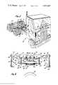
- FIG. 1is a perspective view of a tractor for semi-trailer in which a stabilizing system according to the present invention has been installed;
- FIG. 2is a front elevation, partly in section, of the air bellows and bridging element to which it is attached as seen from a vertical plane passing through the line 2--2, and looking in the direction of the arrows, of FIG. 1;
- FIG. 3is a view similar to FIGURE 1, but showing the air bellows in an expanded state and having added to the drawing of FIG. 2, a schematic view of the air pressure system and its control;
- FIG. 4is a planned view, partly broken away, as seen from a horizontal plane along the line and looking in the direction of the arrows 4--4 in FIG. 3.
- the present inventioncontemplates providing a bridging element 10 between the longitudinal frame members 12 and 14 of a tractor, designated generally as 16, which is designed to pull a semi-trailer (not shown).
- the bridging element 10is preferably disposed directly over the differential housing 18 of the forward one 20 of a pair of axle assemblies 20,22.
- the bridging element 10may comprise a transverse U-shaped channel member 24, having a bottom wall 26 with integrally formed upwardly extending side walls 28a,28b. Each of the side walls 28a,28b may be slotted near both of its extremities at 30 in the manner shown in FIGS. 2 and 3.
- the bottom wall 26is provided with a number of orifices 32, 34, 36, 38 and 40, the locations and functions will hereinafter be explained.
- the channel member 24may be secured to and bridge the space between the longitudinal frame members 12 and 14, by means of pairs of angle plates 42.
- angle plates 42each have a vertical anchoring wall portion 44, which is orificed top and bottom to receive bolts 46, and a 90° angled, also vertical, portion 48, which is slottingly orificed at 50 in register with the orifices 30 in the side walls 28a and 28b of the element 24.
- An air bellowspreferably of the type known as NEW WAY TC Air Bag Assembly, manufactured and sold by the Firestone Tire & Rubber Company of Cleveland, Ohio, is mounted to the underside of the bottom wall 26 of the bridging element 24.
- the air bellows referred tocomprises a pair of circular plates 52,54 between and attached to which is secured and expandable rubber bellows having a compressed configuration as shown in FIG. 2 and an expanded configuration as shown in FIG. 3.
- Projecting outwardly from each of the plates 52 and 54are a pair of bolts 58.
- the air bellows unitis mounted to the underside of the bottom wall 26 of the element 24 by passing the bolts 58 through the orifices 36 and 40 and threading nuts 60 on to the bolts 58.
- a further elongated rectangular plate 62having a neoprene or other resilient buffering plate 64 adhered to its underside, and orifices 66 registering with bolts 67 projecting downwardly from the underside of the plate 54, is secured against the latter by nuts 69.
- the plate 62is further provided with orifices 68 towards its extremities and beyond the farthest point of expansion radially of the rubber bellows 56, and these orifices 68, taken in conjunction with the orifices 32 and 34 in the bottom wall 26 of the element 24, enable compression springs 70 to be attached between the bottom wall 26 and the plate 62.
- the orifice 38 in the bottom wall 26 of the element 24is disposed to register with the orifice 72 in the top plate 52 of the bellows unit and both of these orifices 38 and 72 may be threaded to receive the male threading on a nipple 74 on the end of an air hose 76.
- This air hose 76extends forwardly from the element 24 to a valve 78, preferably located on the dashboard in the cab 80 of the tractor.
- the valve 78may be a Model No. 5400 made and sold by Sealco Corporation of the City of Industry, Calif.
- This valve 78is operated by a rotatable knob 82, and is provided at the opposite end of the valve body from that which the knob 82 projects with three openings 84, 86 and 88.
- An air conduit line 90is provided to connect the truck's compressed air reservoir 92 with the inlet opening 84 in the valve body 83.
- the outlet opening 86receives the other end connection of the line 76 from the air bellows 56.
- the opening 86may also be connected by a further line 94 to an air gauge 96 in line with which may further be provided a pressure switch 98 for an indicator light 100 insertable at the rear of the air gauge 96.
- the opening 88is an air bleed which the valve opens to the line 76 through opening 86 when the knob 82 is turned clockwise to air shut-off position.
- the truck or tractor operatorthen proceeds to drive the truck over the type of road or terrain over which he expects to drive for any distance, and adjusts the air bladder air pressure by turning the knob 82 either clockwise or counter-clockwise to where the operator feels that he is obtaining the smoothest and most stabilized ride.
- the operatorthen notes the reading on the pressure gauge 96 and thereafter maintains the setting of the valve 78 to provide optimum pressure so indicated by the gauge 96 indicated during the remainder of his empty ride.
- the operatorthen turns the valve knob 82 fully to the right, thereby shutting off further communication between the air reservoir 92 and the bladder 56, and simultaneously permitting the air contained in the bladder 56 to be bled off through the valve opening 88.
- the springs 70immediately act to compress the bladder 56 back into its original shape illustrated in FIG. 2.
- the pressure switch 98will be actuated to turn on and maintain in illuminating condition the light 100.
- the latteris, of course, connected to a power supply (not shown).
- the present inventionthus provides a simple, inexpensive and effective means for enabling the frame of a tractor or truck chassis to be pneumatically stabilized in such a manner as to eliminate the jarring and vibrations which are inherently attendant to the operation of a truck or tractor without load and which have proved to be not only a source of discomfort to the operator, but a contributing factor in the deterioration of such vehicles.
Landscapes
- Engineering & Computer Science (AREA)
- Mechanical Engineering (AREA)
- Chemical & Material Sciences (AREA)
- Combustion & Propulsion (AREA)
- Transportation (AREA)
- Fluid-Damping Devices (AREA)
- Vehicle Body Suspensions (AREA)
Abstract
Description
Claims (8)
Priority Applications (1)
| Application Number | Priority Date | Filing Date | Title |
|---|---|---|---|
| US05/627,050US4033607A (en) | 1975-10-30 | 1975-10-30 | Means for attenuating the jarring and vibration of a truck-tractor |
Applications Claiming Priority (1)
| Application Number | Priority Date | Filing Date | Title |
|---|---|---|---|
| US05/627,050US4033607A (en) | 1975-10-30 | 1975-10-30 | Means for attenuating the jarring and vibration of a truck-tractor |
Publications (1)
| Publication Number | Publication Date |
|---|---|
| US4033607Atrue US4033607A (en) | 1977-07-05 |
Family
ID=24512974
Family Applications (1)
| Application Number | Title | Priority Date | Filing Date |
|---|---|---|---|
| US05/627,050Expired - LifetimeUS4033607A (en) | 1975-10-30 | 1975-10-30 | Means for attenuating the jarring and vibration of a truck-tractor |
Country Status (1)
| Country | Link |
|---|---|
| US (1) | US4033607A (en) |
Cited By (8)
| Publication number | Priority date | Publication date | Assignee | Title |
|---|---|---|---|---|
| US4136893A (en)* | 1977-05-31 | 1979-01-30 | American Carrier Equipment, Inc. | Motion damper for a walking beam assembly |
| US4603844A (en)* | 1984-10-30 | 1986-08-05 | Thomas Chen | Cushion isolator |
| US4807713A (en)* | 1987-09-08 | 1989-02-28 | Ottawa Truck Corporation | Suspension system for truck cabs |
| US4993729A (en)* | 1989-09-14 | 1991-02-19 | Volvo Gm Heavy Truck Corporation | Vehicle suspension |
| US5346246A (en)* | 1992-11-23 | 1994-09-13 | Load-Air, Inc. | Automatic air bag suspension control system |
| US5474154A (en)* | 1994-06-15 | 1995-12-12 | Coale; Edward D. | Air brakes adjustment indicator for vehicles such as trucks and the like |
| US5553911A (en)* | 1994-12-15 | 1996-09-10 | Volvo Gm Heavy Truck Corporation | Heavy duty motor vehicle cab suspension |
| US10745065B2 (en) | 2018-04-16 | 2020-08-18 | Howe & Howe Inc. | Vehicle with pneumatically suspended operator compartment |
Citations (6)
| Publication number | Priority date | Publication date | Assignee | Title |
|---|---|---|---|---|
| US2907577A (en)* | 1955-11-30 | 1959-10-06 | Gen Motors Corp | Air suspension assembly for tandem axle vehicle |
| US2952474A (en)* | 1956-02-23 | 1960-09-13 | Gouirand Rene | Pneumatic suspension for vehicles |
| US3104679A (en)* | 1960-04-07 | 1963-09-24 | Gouirand Rene | Means for controlling pressures in pneumatic suspension cushions of a tractor-trailer combination |
| US3214185A (en)* | 1962-03-05 | 1965-10-26 | Int Harvester Co | Control means for a motor vehicle suspension system of the pneumatic type |
| US3224522A (en)* | 1962-10-30 | 1965-12-21 | Olson Trailer & Body Builders | Vehicle spring and axle loading control system |
| US3841694A (en)* | 1973-11-01 | 1974-10-15 | Gen Motors Corp | Vehicle cab mounting means |
- 1975
- 1975-10-30USUS05/627,050patent/US4033607A/ennot_activeExpired - Lifetime
Patent Citations (6)
| Publication number | Priority date | Publication date | Assignee | Title |
|---|---|---|---|---|
| US2907577A (en)* | 1955-11-30 | 1959-10-06 | Gen Motors Corp | Air suspension assembly for tandem axle vehicle |
| US2952474A (en)* | 1956-02-23 | 1960-09-13 | Gouirand Rene | Pneumatic suspension for vehicles |
| US3104679A (en)* | 1960-04-07 | 1963-09-24 | Gouirand Rene | Means for controlling pressures in pneumatic suspension cushions of a tractor-trailer combination |
| US3214185A (en)* | 1962-03-05 | 1965-10-26 | Int Harvester Co | Control means for a motor vehicle suspension system of the pneumatic type |
| US3224522A (en)* | 1962-10-30 | 1965-12-21 | Olson Trailer & Body Builders | Vehicle spring and axle loading control system |
| US3841694A (en)* | 1973-11-01 | 1974-10-15 | Gen Motors Corp | Vehicle cab mounting means |
Cited By (11)
| Publication number | Priority date | Publication date | Assignee | Title |
|---|---|---|---|---|
| US4136893A (en)* | 1977-05-31 | 1979-01-30 | American Carrier Equipment, Inc. | Motion damper for a walking beam assembly |
| US4603844A (en)* | 1984-10-30 | 1986-08-05 | Thomas Chen | Cushion isolator |
| US4807713A (en)* | 1987-09-08 | 1989-02-28 | Ottawa Truck Corporation | Suspension system for truck cabs |
| US4993729A (en)* | 1989-09-14 | 1991-02-19 | Volvo Gm Heavy Truck Corporation | Vehicle suspension |
| US5346246A (en)* | 1992-11-23 | 1994-09-13 | Load-Air, Inc. | Automatic air bag suspension control system |
| AU663981B2 (en)* | 1992-11-23 | 1995-10-26 | Load-Air Inc | Automatic air bag suspension control system |
| US5584497A (en)* | 1992-11-23 | 1996-12-17 | Load-Air, Inc. | Automatic air bag suspension control system |
| US5474154A (en)* | 1994-06-15 | 1995-12-12 | Coale; Edward D. | Air brakes adjustment indicator for vehicles such as trucks and the like |
| WO1995034768A1 (en)* | 1994-06-15 | 1995-12-21 | Coale Edward D | Air brakes adjustment indicator for vehicles such as trucks and the like |
| US5553911A (en)* | 1994-12-15 | 1996-09-10 | Volvo Gm Heavy Truck Corporation | Heavy duty motor vehicle cab suspension |
| US10745065B2 (en) | 2018-04-16 | 2020-08-18 | Howe & Howe Inc. | Vehicle with pneumatically suspended operator compartment |
Similar Documents
| Publication | Publication Date | Title |
|---|---|---|
| US3836161A (en) | Leveling system for vehicles with optional manual or automatic control | |
| US4256326A (en) | Liftable tandem axle suspension | |
| US3580609A (en) | Fifth wheel with load-transferring device | |
| US3285621A (en) | Wheeled vehicle suspension | |
| US3826516A (en) | Fifth wheel mounting structure | |
| US8306696B2 (en) | Method and system for aligning a vehicle with an artificial horizon | |
| US5584497A (en) | Automatic air bag suspension control system | |
| US20040094346A1 (en) | Air bladder suspension system for three-wheeled vehicle | |
| US4033607A (en) | Means for attenuating the jarring and vibration of a truck-tractor | |
| US20210039469A1 (en) | Control unit for air management system | |
| CA2447898C (en) | Radio frequency-controlled axle/suspension lift system | |
| US5271638A (en) | Truck steering stabilizer | |
| US2996312A (en) | Fifth wheel weight distributor | |
| US3961826A (en) | Suspension unit | |
| JP2009535252A (en) | Air storage system for air suspension system in heavy vehicles | |
| US4279430A (en) | Fifth-wheel suspension system | |
| US3870336A (en) | Vehicle suspension | |
| US2816776A (en) | Wheeled tandem attachment for coupling tractor-trailers | |
| US3315978A (en) | Axle lift (radius rod) | |
| US6254192B1 (en) | Dump trailer | |
| US3347563A (en) | Fifth-wheel elevating and level controlling air jack for semi-trailer dollies | |
| US4865349A (en) | Air suspension deflation control system with automatic reinflation and control reset | |
| US3439935A (en) | Fifth wheel tractor | |
| US4700968A (en) | Liftable axle with load control | |
| US3844582A (en) | Leveling and stabilizing device |
Legal Events
| Date | Code | Title | Description |
|---|---|---|---|
| STCF | Information on status: patent grant | Free format text:PATENTED FILE - (OLD CASE ADDED FOR FILE TRACKING PURPOSES) | |
| AS | Assignment | Owner name:CAMERON, JOHN, 13726 DE ALCALA DRIVE, LA MIRADA, C Free format text:ASSIGNMENT OF ASSIGNORS INTEREST.;ASSIGNOR:JEFFRIES TRUCK PARTS & EQUIPMENT, INC., A CORP OF CA.;REEL/FRAME:004526/0556 Effective date:19811119 | |
| AS | Assignment | Owner name:UTILITY TRAILER MANUFACTURING COMPANY, P.O. BOX 12 Free format text:ASSIGNMENT OF ASSIGNORS INTEREST.;ASSIGNOR:CAMERON, JOHN S., INDIVIDUALLY AND AS TRUSTEE FOR LANCE E. TIDWELL;REEL/FRAME:004686/0625 Effective date:19870126 Owner name:SAUER AXLE-SUSPENSIONS, INC., 100 COSTA ROAD, CONC Free format text:ASSIGNMENT OF ASSIGNORS INTEREST.;ASSIGNOR:UTILITY TRAILER MFG. COMPANY;REEL/FRAME:004686/0626 Effective date:19870216 Owner name:UTILITY TRAILER MANUFACTURING COMPANY,CALIFORNIA Free format text:ASSIGNMENT OF ASSIGNORS INTEREST;ASSIGNOR:CAMERON, JOHN S., INDIVIDUALLY AND AS TRUSTEE FOR LANCE E. TIDWELL;REEL/FRAME:004686/0625 Effective date:19870126 Owner name:SAUER AXLE-SUSPENSIONS, INC.,CANADA Free format text:ASSIGNMENT OF ASSIGNORS INTEREST;ASSIGNOR:UTILITY TRAILER MFG. COMPANY;REEL/FRAME:004686/0626 Effective date:19870216 | |
| AS | Assignment | Owner name:SAUER PRODUCTS, INC., PENNSYLVANIA Free format text:ASSIGNMENT OF ASSIGNORS INTEREST;ASSIGNOR:SAUER AXLE-SUSPENSIONS, INC.;REEL/FRAME:006604/0930 Effective date:19930623 Owner name:LOAD-AIR, INC., PENNSYLVANIA Free format text:ASSIGNMENT OF ASSIGNORS INTEREST;ASSIGNOR:SAUER PRODUCTS, INC.;REEL/FRAME:006604/0933 Effective date:19930623 |