US4033144A - Flexible coupling - Google Patents
Flexible couplingDownload PDFInfo
- Publication number
- US4033144A US4033144AUS05/659,129US65912976AUS4033144AUS 4033144 AUS4033144 AUS 4033144AUS 65912976 AUS65912976 AUS 65912976AUS 4033144 AUS4033144 AUS 4033144A
- Authority
- US
- United States
- Prior art keywords
- intermediate member
- coupling
- tripodic
- strips
- load
- Prior art date
- Legal status (The legal status is an assumption and is not a legal conclusion. Google has not performed a legal analysis and makes no representation as to the accuracy of the status listed.)
- Expired - Lifetime
Links
Images


Classifications
- F—MECHANICAL ENGINEERING; LIGHTING; HEATING; WEAPONS; BLASTING
- F16—ENGINEERING ELEMENTS AND UNITS; GENERAL MEASURES FOR PRODUCING AND MAINTAINING EFFECTIVE FUNCTIONING OF MACHINES OR INSTALLATIONS; THERMAL INSULATION IN GENERAL
- F16D—COUPLINGS FOR TRANSMITTING ROTATION; CLUTCHES; BRAKES
- F16D3/00—Yielding couplings, i.e. with means permitting movement between the connected parts during the drive
- F16D3/50—Yielding couplings, i.e. with means permitting movement between the connected parts during the drive with the coupling parts connected by one or more intermediate members
- F16D3/60—Yielding couplings, i.e. with means permitting movement between the connected parts during the drive with the coupling parts connected by one or more intermediate members comprising pushing or pulling links attached to both parts
- F16D3/62—Yielding couplings, i.e. with means permitting movement between the connected parts during the drive with the coupling parts connected by one or more intermediate members comprising pushing or pulling links attached to both parts the links or their attachments being elastic
- Y—GENERAL TAGGING OF NEW TECHNOLOGICAL DEVELOPMENTS; GENERAL TAGGING OF CROSS-SECTIONAL TECHNOLOGIES SPANNING OVER SEVERAL SECTIONS OF THE IPC; TECHNICAL SUBJECTS COVERED BY FORMER USPC CROSS-REFERENCE ART COLLECTIONS [XRACs] AND DIGESTS
- Y10—TECHNICAL SUBJECTS COVERED BY FORMER USPC
- Y10S—TECHNICAL SUBJECTS COVERED BY FORMER USPC CROSS-REFERENCE ART COLLECTIONS [XRACs] AND DIGESTS
- Y10S464/00—Rotary shafts, gudgeons, housings, and flexible couplings for rotary shafts
- Y10S464/902—Particular material
- Y10S464/903—Nonmetal
Definitions
- This inventionrelates to flexible couplings for connecting and transmitting torque between two shafts or other rotatable parts and especially to a coupling that can accommodate a certain amount of angular or parallel misalignment, or both, between the shafts. More particularly, the invention relates to a flexible coupling capable of connecting rotary shafts with their respective axes angularly and/or laterally misaligned while maintaining a generally constant velocity relationship.
- Another object of the inventionis to connect a rotary drive to a rotary load where the axes of the drive and load are angularly misaligned, while providing a constant velocity relationship between the rotary drive and the rotary load.
- Another object of the inventionis to provide a non-elastomeric flexible coupling to connect a rotary drive to a rotary load wherein the coupling provides much greater flexibility than is provided by conventional non-elastomeric types of flexible couplings.
- Still another object of the inventionis to connect a rotary drive to a rotary load wherein the axes of the drive and load may be angularly misaligned to the extent of 10 degrees or more.
- the couplingincludes an input hub on the drive shaft and an output hub on the load shaft. Interposed between the two hubs is an intermediate plate member generally perpendicular to the respective axes and connected on one side to the input hub through one tripodic connection assembly and on the other side to the output hub through another tripodic connection assembly.
- Each of the tripodic connection assembliescomprises three flexible flat elements of equal length generally arranged in triangular form and when unflexed, in a common plane generally perpendicular to the respective hub axis.
- the three flexible elements of each assemblyare connected at rigid connections to the intermediate member at one end and to the respective hub at the other end.
- the three respective connections for corresponding endsare at symmetrically spaced locations around a circumscribing circle.
- the flexible elementsare adapted to flex intermediate their ends to accommodate angular and parallel misalignment between the respective axes of the hubs preferably to provide a constant velocity relationship between the rotary drive and the rotary load regardless of the angular or parallel misalignment.
- FIG. 1is an elevational view of a flexible coupling embodying the invention
- FIG. 2is a sectional view taken on the line 2--2 of FIG. 1;
- FIG. 3is an elevational view similar to FIG. 1 showing the flexible coupling of the invention connecting a rotary drive to a rotary load with its axis at an angle of about 8 degrees to the axis of the rotary drive;
- FIG. 4is a sectional view taken on the line 4--4 of FIG. 3;
- FIG. 5is an elevational view taken on the line 5--5 of FIG. 4 illustrating the condition of the flexing elements at one location during a 360° rotation of the coupling;
- FIG. 6is an elevational view taken on the line 6--6 of FIG. 4 illustrating the condition of the flexing elements at another point in a 360° rotation of the flexible coupling;
- FIG. 7is an elevational view of an alternate form of flexible coupling embodying the invention.
- FIG. 8is a sectional view taken on the line 8--8 of FIG. 7;
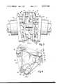
- FIG. 9is a sectional view taken on the line 9--9 of FIG. 10 through a flexible coupling embodying a modified form of the invention.
- FIG. 10is a sectional view taken on the line 10--10 of FIG. 9.
- FIGS. 1 to 6there is shown a flexible coupling 10 for connecting a rotary drive shaft 11 to a rotary load shaft 12.
- the couplingincludes an input hub 13 mounted on the drive shaft 11 and an output hub 14 mounted on the load shaft 12.
- the hubs 13 and 14are secured to the shafts 11 and 12 by keys 15 and 16 respectively, seated in slots in the respective hub and shaft.
- Located between the two hubs 13 and 14is a flat three-pointed intermediate plate member 19 positioned generally perpendicular to the axes of the shafts 11 and 12.
- the input hub 13is connected to the intermediate plate member 19 by means of a tripodic connection assembly 20 including three flat flexible resilient steel strips 21, 22 and 23 of equal length.
- the strips 21, 22 and 23are arranged when unflexed in a common plane generally perpendicular to the hub axis and in a triangular form.
- the strips 21, 22 and 23are connected at one end to the input hub 13 by bolts 24 which anchor the respective ends of the strips 21, 22 and 23 to mounting posts 25 formed on a radial three-pointed flange 26 on the input hub 13.
- the three resulting connection pointsare located at symmetrically spaced locations around a circumscribing circle to define an equilateral triangle.
- the opposite ends of the respective strips 21, 22 and 23are connected to the intermediate plate member 19 at posts 27 formed on the member 19 and adapted to receive rivets 28. These posts are likewise located at symmetrically spaced locations around a circumscribing circle to define an equilateral triangle concentric with but offset from the triangle defined by the opposite ends of the strips 21, 22 and 23. Both ends of each strip 21, 22 and 23 are held between curved-faced washers 29.
- the output hub 14is connected to the intermediate member 19 by another tripodic connection assembly 30 including three flat flexible steel strips 31, 32 and 33 which are, in all respects, identical to the strips 21, 22 and 23.
- the strips 31, 32 and 33are fastened by bolts 34 to posts 35 on a radial three-pointed flange 36 on the output hub 14.
- the connection pointsare located at symmetrically spaced locations around a circumscribing circle to define an equilateral triangle concentric with and in the same relative orientation as the triangle defined by the connection points on the input hub 13.
- connection points for the flexible strips 31, 32 and 33 to the intermediate member 19correspond exactly to the connection points for the strips 21, 22 and 23.
- FIG. 3illustrates a typical operating condition for the coupling wherein it will be seen that the shafts 11 and 12 are located with their axes angularly misaligned from one another.
- the angle defined by the axes for the shaftsis about 8° in the typical circumstance shown.
- This misalignmentis accommodated in the coupling by means of the two tripodic connection assemblies 20 and 30, and it will be seen that the respective flexible strips 21, 22 and 23 and 31, 32 and 33 are flexed depending upon their position around the central axis in a manner sufficient to accommodate the angular misalignment and also to transmit torque from one shaft to the other through the coupling.
- the stripsare formed, for example of AISI 1095 steel to provide the desired flexibility as well as adequate tensile strength.
- FIGS. 5 and 6Two typical conditions of flexing are illustrated in FIGS. 5 and 6 which show the strips 22 and 32 flexed with their ends in two non-parallel planes. This produces the compound bending shown at the particular location in the 360° rotation illustrated at FIG. 5.
- the strips 21 and 31are flexed in a pure bending condition at the particular location illustrated in FIG. 5.
- FIG. 4is the better illustration of pure bending.
- FIG. 6shows torsional twist as well as bending.
- the flexing of the stripschanges their effective length or more particularly changes the distance between the connection points. Accordingly, the effective length of the strips varies in a cyclic manner during each full rotation of the coupling. This cyclic change in the effective length of the strips is completed for each strip in each 360 degrees of coupling rotation and is the same for each strip since all of the strips are equal in shape and length in their assembled geometry relative to the coupling.
- tripodic coupling intermediate memberaccomplishes the same purpose in tangential and radial accommodations to the changes in effective lengths of the three connecting flexing strips.
- the 120° angle formed between adjacent stripsresults in a pattern of instantaneous link length relationship which is repeated for each 120 degrees of rotation of the coupling.
- the intermediate memberexperiences a small-amplitude cyclic eccentric displacement which has a frequency three times the frequency of coupling rotation.
- the connection points for the strips 21, 22 and 23 to the hub 13correspond generally (in a geometric sense) to the connection points for the strips 31, 32 and 33 at the output hub 14, the effective length variations compliment one another and accordingly, a constant velocity relationship exists between the drive shaft 11 and the load shaft 12.
- FIGS. 7 and 8illustrate a modified form of coupling embodying the invention and which differs from the coupling of FIGS. 1 to 6 primarily in the location of the connection points for the flexible strips.
- the coupling 40 of FIGS. 7 and 8connects a drive shaft 41 to a load shaft 42, the drive shaft having an input hub 43 mounted thereon and the load shaft 42 having an output hub 44.
- An intermediate member 45is located between the two hubs and has three radially extending symmetrically spaced arms 46, 47 and 48, each arm providing two circumferentially spaced connection points.
- the input hub 43is connected to the intermediate member 45 by a tripodic connection assembly 50 including three flexible strips 51, 52 and 53, while the output hub 54 is connected to the intermediate member 45 by a tripodic connection assembly 60 also including three flexible strips 61, 62 and 63.
- the strips 51, 52, 53, 61, 62 and 63are molded from a suitable engineering grade plastic material -- for example, an acetal resin such as "DELRIN” or "CELCON" and have enlarged end portions to provide reinforcement at the connection points.
- the strips 51, 52 and 53are connected at one end at symmetrically spaced locations to a radial flange 54 on the hub 43 using bolts 55, spacer sleeves 56 and nuts 57.
- the opposite ends of the strips 51, 52 and 53are connected to the arms 46, 47 and 48 of the intermediate member 45 using bolts 58 and nuts 59.
- One of the strips 51, 52 and 53is connected to each of the three arms 46, 47 and 48 so that the connection points are at symmetrically spaced locations about a circumscribing circle.
- the strips 61, 62 and 63are connected at one end, at symmetrically spaced locations to a radial flange 64 on the hub 44 using bolts 65, spacer sleeves 66 and nuts 67 to provide connections that are offset approximately 60° from corresponding connection points on the radial flange 54.
- the opposite ends of each of the strips 61, 62 and 63are connected to the arms 46, 47 and 48 of the intermediate member 45 at corresponding opposite connection points on the arms from the connection points for the strips 51, 52 and 53.
- the connectionsare made using bolts 58 and nuts 59 as best seen in FIG. 7.
- connection pointscorrespond to any of the other connection points for either of the tripodic connection assemblies 50 and 60 so that the triangular form defined by the strips 51, 52 and 53 is 60° out of angular orientation relative to the triangular form defined by the strips 61, 62 and 63.
- This arrangementproduces a coupling of narrower axial width since there is no interference between the connections.
- a pure constant velocity relationship between the respective shafts 41 and 42may not be obtained.
- FIGS. 9 and 10illustrate still another modified form of coupling embodying the invention which is particularly useful where any end float between the shafts is to be avoided and wherein certain end loads may be expected.
- the coupling 70is adapted to connect a drive shaft 71 to a load shaft 72.
- the coupling 70includes an input hub 73 on the drive shaft 71 and an output hub 74 on the load shaft 72.
- the hubs 73 and 74are secured to the shafts 71 and 72 by keys 75 and 76 respectively seated in slots 77 and 78 the respective hub and shaft.
- Located between the two hubs 73 and 74is a three-pointed intermediate member 79 positioned generally perpendicular to the axes of the shafts 71 and 72.
- the input hub 73is connected to the intermediate member 79 by means of a tripodic connection assembly 80 including three flat flexible resilient steel strips 81, 82 and 83 formed of two superposed laminations to provide certain desirable flexing characteristics.
- the laminationsare formed, for example of AISI 1065 steel.
- the strips 81, 82 and 83are arranged in a triangular form and (when unflexed) in a common plane generally perpendicular to the hub axis.
- the strips 81, 82 and 83are connected at one end to a radial flange 84 on the input hub 73 by bolts 85, spacer sleeves 86 and nuts 87.
- the opposite ends of the strips 81, 82 and 83are connected to the intermediate member 79 by bolts 88 and nuts 89.
- the resulting connection patternis best illustrated in FIG. 10.
- the output hub 74is connected to the intermediate member 79 by another tripodic connection assembly 90 including three flat flexible steel strips 91, 92 and 93 that are, identical to the strips 81, 82 and 83.
- the strips 91, 92 and 93are fastened to a radial flange 94 on the hub 74 by bolts 96, spacer sleeve 97 and nuts 98, at three connections located at symmetrically spaced locations around a circumscribing circle.
- FIGS. 9 and 10also has a flexible end load transmitting quill 99 located between the two shafts 71 and 72.
- the quill 99is press fitted, bonded or otherwise secured at each end in the openings 101 and 102 in the respective hubs 73 and 74 and bears against the ends of the respective shafts 71 and 72.
- the quillextends through a central opening 100 in the intermediate member 79.
Landscapes
- Engineering & Computer Science (AREA)
- General Engineering & Computer Science (AREA)
- Mechanical Engineering (AREA)
- Transmission Devices (AREA)
Abstract
Description
Claims (10)
Priority Applications (1)
| Application Number | Priority Date | Filing Date | Title |
|---|---|---|---|
| US05/659,129US4033144A (en) | 1976-02-18 | 1976-02-18 | Flexible coupling |
Applications Claiming Priority (1)
| Application Number | Priority Date | Filing Date | Title |
|---|---|---|---|
| US05/659,129US4033144A (en) | 1976-02-18 | 1976-02-18 | Flexible coupling |
Publications (1)
| Publication Number | Publication Date |
|---|---|
| US4033144Atrue US4033144A (en) | 1977-07-05 |
Family
ID=24644160
Family Applications (1)
| Application Number | Title | Priority Date | Filing Date |
|---|---|---|---|
| US05/659,129Expired - LifetimeUS4033144A (en) | 1976-02-18 | 1976-02-18 | Flexible coupling |
Country Status (1)
| Country | Link |
|---|---|
| US (1) | US4033144A (en) |
Cited By (25)
| Publication number | Priority date | Publication date | Assignee | Title |
|---|---|---|---|---|
| US4187699A (en)* | 1976-10-29 | 1980-02-12 | The Zeller Corporation | Universal joint for connecting shafts |
| US4282723A (en)* | 1979-10-09 | 1981-08-11 | Richard Schmidt | Coupling |
| WO1981002452A1 (en)* | 1980-02-27 | 1981-09-03 | I Chivari | Hooke's coupling |
| US4314460A (en)* | 1979-05-08 | 1982-02-09 | Mayfield Alfred B | Linked torsional misalignment coupling |
| FR2488958A1 (en)* | 1980-08-22 | 1982-02-26 | Lord Corp | COUPLING WITH RODS TRANSMITTING ROTATION MOVEMENTS |
| US4460345A (en)* | 1979-10-31 | 1984-07-17 | Ilie Chivari | Shaft coupling |
| US4516958A (en)* | 1983-11-03 | 1985-05-14 | Hidden Valley Associates, Inc. | Flexible shaft coupling device |
| US4588388A (en)* | 1980-02-27 | 1986-05-13 | Ilie Chivari | Shaft coupling |
| GB2191562A (en)* | 1986-06-14 | 1987-12-16 | John Cannon Braithwaite | Shaft flexible coupling |
| US4729753A (en)* | 1985-11-04 | 1988-03-08 | Bell Helicopter Textron Inc. | Constant velocity elastomeric bearing joint |
| US4850933A (en)* | 1987-09-21 | 1989-07-25 | Mobil Oil Corporation | Flexible coupling |
| GB2226382A (en)* | 1988-10-21 | 1990-06-27 | Filtermist International Limit | Mounting a rotor in a separator |
| US5137495A (en)* | 1989-04-13 | 1992-08-11 | Windmoeller & Hoelscher | Shaft coupling allowing for an offset of axes |
| US5221232A (en)* | 1989-01-12 | 1993-06-22 | Zero-Max, Inc. | Flexible disc-like coupling element |
| US5415587A (en)* | 1993-03-03 | 1995-05-16 | J. L. Behmer Corporation | Flexible coupling |
| US6471435B1 (en)* | 1999-11-05 | 2002-10-29 | Multibeam Systems, Inc. | Flexural joint |
| US20090020238A1 (en)* | 2007-07-16 | 2009-01-22 | Horatiu Ion Barbulescu | Single Piece Spacer Support |
| CN102927147A (en)* | 2011-08-08 | 2013-02-13 | 基尔谢中央传动有限公司 | Coupling unit for connecting a drive with an output |
| US8529359B1 (en) | 2011-12-01 | 2013-09-10 | Frank Vresk | Shaft coupling system |
| WO2014004687A1 (en)* | 2012-06-27 | 2014-01-03 | Kla-Tencor Corporation | Flexible coupling |
| US20140057523A1 (en)* | 2008-02-15 | 2014-02-27 | Boaz Leicht | Interconnectible building elements for intellectual challenge games |
| US20140057730A1 (en)* | 2012-08-24 | 2014-02-27 | Ruben Steinhauser | Connecting joint for a connecting shaft and connecting shaft with such a connecting joint |
| US8920249B2 (en) | 2013-03-15 | 2014-12-30 | Paccar Inc | High angle universal coupling with constant or near constant characteristics |
| EP2626579A3 (en)* | 2012-02-10 | 2015-10-07 | ZF Friedrichshafen AG | Elastic double torsional coupling |
| US20180290284A1 (en)* | 2015-06-30 | 2018-10-11 | Atlas Copco Industrial Technique Ab | Electric power tool |
Citations (4)
| Publication number | Priority date | Publication date | Assignee | Title |
|---|---|---|---|---|
| US2181888A (en)* | 1938-05-27 | 1939-12-05 | Gustin Harold Horatio | Flexible coupling |
| US2864245A (en)* | 1954-12-28 | 1958-12-16 | Walter E Amberg | Rotary torque transmitting joint |
| US3481158A (en)* | 1968-07-22 | 1969-12-02 | Kaman Corp | Flexible coupling |
| US3592021A (en)* | 1969-06-30 | 1971-07-13 | Kaman Aerospace Corp | Flexible coupling |
- 1976
- 1976-02-18USUS05/659,129patent/US4033144A/ennot_activeExpired - Lifetime
Patent Citations (4)
| Publication number | Priority date | Publication date | Assignee | Title |
|---|---|---|---|---|
| US2181888A (en)* | 1938-05-27 | 1939-12-05 | Gustin Harold Horatio | Flexible coupling |
| US2864245A (en)* | 1954-12-28 | 1958-12-16 | Walter E Amberg | Rotary torque transmitting joint |
| US3481158A (en)* | 1968-07-22 | 1969-12-02 | Kaman Corp | Flexible coupling |
| US3592021A (en)* | 1969-06-30 | 1971-07-13 | Kaman Aerospace Corp | Flexible coupling |
Cited By (37)
| Publication number | Priority date | Publication date | Assignee | Title |
|---|---|---|---|---|
| US4187699A (en)* | 1976-10-29 | 1980-02-12 | The Zeller Corporation | Universal joint for connecting shafts |
| US4314460A (en)* | 1979-05-08 | 1982-02-09 | Mayfield Alfred B | Linked torsional misalignment coupling |
| US4282723A (en)* | 1979-10-09 | 1981-08-11 | Richard Schmidt | Coupling |
| US4460345A (en)* | 1979-10-31 | 1984-07-17 | Ilie Chivari | Shaft coupling |
| US4588388A (en)* | 1980-02-27 | 1986-05-13 | Ilie Chivari | Shaft coupling |
| WO1981002452A1 (en)* | 1980-02-27 | 1981-09-03 | I Chivari | Hooke's coupling |
| EP0035283A1 (en)* | 1980-02-27 | 1981-09-09 | Ilie Chivari | Shaft coupling |
| FR2488958A1 (en)* | 1980-08-22 | 1982-02-26 | Lord Corp | COUPLING WITH RODS TRANSMITTING ROTATION MOVEMENTS |
| US4377386A (en)* | 1980-08-22 | 1983-03-22 | Lord Corporation | Link coupling |
| US4516958A (en)* | 1983-11-03 | 1985-05-14 | Hidden Valley Associates, Inc. | Flexible shaft coupling device |
| US4729753A (en)* | 1985-11-04 | 1988-03-08 | Bell Helicopter Textron Inc. | Constant velocity elastomeric bearing joint |
| GB2191562A (en)* | 1986-06-14 | 1987-12-16 | John Cannon Braithwaite | Shaft flexible coupling |
| US4850933A (en)* | 1987-09-21 | 1989-07-25 | Mobil Oil Corporation | Flexible coupling |
| GB2226382A (en)* | 1988-10-21 | 1990-06-27 | Filtermist International Limit | Mounting a rotor in a separator |
| GB2226382B (en)* | 1988-10-21 | 1992-04-15 | Filtermist International Limit | Separator and method of operating same |
| US5221232A (en)* | 1989-01-12 | 1993-06-22 | Zero-Max, Inc. | Flexible disc-like coupling element |
| US5387157A (en)* | 1989-01-12 | 1995-02-07 | Zero-Max, Inc. | Flexible disc-like coupling element |
| US5137495A (en)* | 1989-04-13 | 1992-08-11 | Windmoeller & Hoelscher | Shaft coupling allowing for an offset of axes |
| US5415587A (en)* | 1993-03-03 | 1995-05-16 | J. L. Behmer Corporation | Flexible coupling |
| US6471435B1 (en)* | 1999-11-05 | 2002-10-29 | Multibeam Systems, Inc. | Flexural joint |
| US20090020238A1 (en)* | 2007-07-16 | 2009-01-22 | Horatiu Ion Barbulescu | Single Piece Spacer Support |
| US20140057523A1 (en)* | 2008-02-15 | 2014-02-27 | Boaz Leicht | Interconnectible building elements for intellectual challenge games |
| US9061200B2 (en)* | 2008-02-15 | 2015-06-23 | Boaz Leicht | Interconnectible building elements for intellectual challenge games |
| US8784219B2 (en)* | 2011-08-08 | 2014-07-22 | Centa-Antriebe Kirschey Gmbh | Flexible homokinetic coupling |
| CN102927147A (en)* | 2011-08-08 | 2013-02-13 | 基尔谢中央传动有限公司 | Coupling unit for connecting a drive with an output |
| US20130040742A1 (en)* | 2011-08-08 | 2013-02-14 | Jochen Exner | Flexible homokinetic coupling |
| CN102927147B (en)* | 2011-08-08 | 2016-08-03 | 基尔谢中央传动有限公司 | It is used for connecting the joint unit of driver element and driven unit |
| US8529359B1 (en) | 2011-12-01 | 2013-09-10 | Frank Vresk | Shaft coupling system |
| EP2626579A3 (en)* | 2012-02-10 | 2015-10-07 | ZF Friedrichshafen AG | Elastic double torsional coupling |
| EP3339669A1 (en)* | 2012-02-10 | 2018-06-27 | ZF Friedrichshafen AG | Elastic double torsional coupling |
| US9377058B2 (en) | 2012-06-27 | 2016-06-28 | Kla-Tencor Corporation | Flexible coupling |
| WO2014004687A1 (en)* | 2012-06-27 | 2014-01-03 | Kla-Tencor Corporation | Flexible coupling |
| US20140057730A1 (en)* | 2012-08-24 | 2014-02-27 | Ruben Steinhauser | Connecting joint for a connecting shaft and connecting shaft with such a connecting joint |
| US8920249B2 (en) | 2013-03-15 | 2014-12-30 | Paccar Inc | High angle universal coupling with constant or near constant characteristics |
| US20180290284A1 (en)* | 2015-06-30 | 2018-10-11 | Atlas Copco Industrial Technique Ab | Electric power tool |
| US20220152807A1 (en)* | 2015-06-30 | 2022-05-19 | Atlas Copco Industrial Technique Ab | Electric power tool |
| US11701768B2 (en)* | 2015-06-30 | 2023-07-18 | Atlas Copco Industrial Technique Ab | Electric power tool |
Similar Documents
| Publication | Publication Date | Title |
|---|---|---|
| US4033144A (en) | Flexible coupling | |
| US5387157A (en) | Flexible disc-like coupling element | |
| US5215502A (en) | Constant velocity elastomeric joint | |
| US2855767A (en) | Yieldable coupling | |
| US3988906A (en) | Flexible coupling | |
| US4690661A (en) | Torsional stress distribution flexible coupling | |
| GB2049104A (en) | Universal joint | |
| GB2041494A (en) | Flexible couplings | |
| US6500071B1 (en) | Flexible coupling | |
| US3623339A (en) | Bellows flexible joint | |
| US3499299A (en) | Flexible universal joint | |
| US4436515A (en) | Articulation device having a double universal joint and a ball joint unit | |
| US4516958A (en) | Flexible shaft coupling device | |
| US3177684A (en) | Rotary power transmitting device | |
| US3411324A (en) | Shaft coupling | |
| CA1264603A (en) | Dual gimbal coupling | |
| US4187699A (en) | Universal joint for connecting shafts | |
| US3798924A (en) | Shaft coupling and element therefor | |
| US3461688A (en) | Constant velocity universal joint | |
| US3004409A (en) | Flexible coupling | |
| US2142784A (en) | Universal coupling | |
| US4543075A (en) | Flexible couplings | |
| US4194372A (en) | Flexible drive coupling | |
| US3611750A (en) | Flexible torsionally-resilient coupling | |
| WO1991016550A1 (en) | Flexible coupling for joining a driving member to a driven member |
Legal Events
| Date | Code | Title | Description |
|---|---|---|---|
| STCF | Information on status: patent grant | Free format text:PATENTED FILE - (OLD CASE ADDED FOR FILE TRACKING PURPOSES) | |
| AS | Assignment | Owner name:ALLEN COUPLINGS INCORPORATED, 13109 WESTCHESTER TR Free format text:ASSIGNMENT OF ASSIGNORS INTEREST.;ASSIGNOR:ALLEN, CLIFFORD H.;REEL/FRAME:004595/0136 Effective date:19860824 Owner name:ALLEN COUPLINGS INCORPORATED,OHIO Free format text:ASSIGNMENT OF ASSIGNORS INTEREST;ASSIGNOR:ALLEN, CLIFFORD H.;REEL/FRAME:004595/0136 Effective date:19860824 | |
| AS | Assignment | Owner name:LOVEJOY, INC., 2655 WISCONSIN AVENUE, DOWNERS GROV Free format text:SECURITY INTEREST;ASSIGNOR:ALLEN COUPLINGS INCORPORATED;REEL/FRAME:004610/0336 Owner name:LOVEJOY, INC., 2655 WISCONSIN AVENUE, DOWNERS GROV Free format text:SECURITY INTEREST;ASSIGNOR:ALLEN COUPLINGS INCORPORATED;REEL/FRAME:004610/0336 Effective date:20000204 | |
| AS | Assignment | Owner name:LOVEJOY, INC., 2655 WISCONSIN AVE., DOWNERS GROVE, Free format text:ASSIGNMENT OF ASSIGNORS INTEREST.;ASSIGNOR:ALLEN COUPLINGS INCORPORATED;REEL/FRAME:004997/0462 Effective date:19881228 | |
| AS | Assignment | Owner name:NORTHERN TRUST COMPANY, ILLINOIS Free format text:CONDITIONAL ASSIGNMENT;ASSIGNOR:LOVEJOY, INC.;REEL/FRAME:005461/0564 Effective date:19900925 |