US4031295A - Combination housing with compartment and ejector mechanism for ejecting a battery therefrom - Google Patents
Combination housing with compartment and ejector mechanism for ejecting a battery therefromDownload PDFInfo
- Publication number
- US4031295A US4031295AUS05/665,793US66579376AUS4031295AUS 4031295 AUS4031295 AUS 4031295AUS 66579376 AUS66579376 AUS 66579376AUS 4031295 AUS4031295 AUS 4031295A
- Authority
- US
- United States
- Prior art keywords
- battery
- compartment
- lever arm
- hinge
- ejector mechanism
- Prior art date
- Legal status (The legal status is an assumption and is not a legal conclusion. Google has not performed a legal analysis and makes no representation as to the accuracy of the status listed.)
- Expired - Lifetime
Links
- 230000007246mechanismEffects0.000titleabstractdescription27
- 230000003014reinforcing effectEffects0.000claims2
- 239000004033plasticSubstances0.000description7
- 230000009471actionEffects0.000description5
- 239000000463materialSubstances0.000description2
- DHKHKXVYLBGOIT-UHFFFAOYSA-N1,1-DiethoxyethaneChemical compoundCCOC(C)OCCDHKHKXVYLBGOIT-UHFFFAOYSA-N0.000description1
- 229920005123Celcon®Polymers0.000description1
- 230000006978adaptationEffects0.000description1
- 238000010276constructionMethods0.000description1
- 230000006872improvementEffects0.000description1
- 238000004519manufacturing processMethods0.000description1
- 230000004048modificationEffects0.000description1
- 238000012986modificationMethods0.000description1
- 239000002991molded plasticSubstances0.000description1
- 230000008092positive effectEffects0.000description1
- 230000009467reductionEffects0.000description1
Images
Classifications
- H—ELECTRICITY
- H01—ELECTRIC ELEMENTS
- H01M—PROCESSES OR MEANS, e.g. BATTERIES, FOR THE DIRECT CONVERSION OF CHEMICAL ENERGY INTO ELECTRICAL ENERGY
- H01M50/00—Constructional details or processes of manufacture of the non-active parts of electrochemical cells other than fuel cells, e.g. hybrid cells
- H01M50/20—Mountings; Secondary casings or frames; Racks, modules or packs; Suspension devices; Shock absorbers; Transport or carrying devices; Holders
- H01M50/204—Racks, modules or packs for multiple batteries or multiple cells
- H01M50/207—Racks, modules or packs for multiple batteries or multiple cells characterised by their shape
- H01M50/213—Racks, modules or packs for multiple batteries or multiple cells characterised by their shape adapted for cells having curved cross-section, e.g. round or elliptic
- Y—GENERAL TAGGING OF NEW TECHNOLOGICAL DEVELOPMENTS; GENERAL TAGGING OF CROSS-SECTIONAL TECHNOLOGIES SPANNING OVER SEVERAL SECTIONS OF THE IPC; TECHNICAL SUBJECTS COVERED BY FORMER USPC CROSS-REFERENCE ART COLLECTIONS [XRACs] AND DIGESTS
- Y02—TECHNOLOGIES OR APPLICATIONS FOR MITIGATION OR ADAPTATION AGAINST CLIMATE CHANGE
- Y02E—REDUCTION OF GREENHOUSE GAS [GHG] EMISSIONS, RELATED TO ENERGY GENERATION, TRANSMISSION OR DISTRIBUTION
- Y02E60/00—Enabling technologies; Technologies with a potential or indirect contribution to GHG emissions mitigation
- Y02E60/10—Energy storage using batteries
- Y—GENERAL TAGGING OF NEW TECHNOLOGICAL DEVELOPMENTS; GENERAL TAGGING OF CROSS-SECTIONAL TECHNOLOGIES SPANNING OVER SEVERAL SECTIONS OF THE IPC; TECHNICAL SUBJECTS COVERED BY FORMER USPC CROSS-REFERENCE ART COLLECTIONS [XRACs] AND DIGESTS
- Y10—TECHNICAL SUBJECTS COVERED BY FORMER USPC
- Y10S—TECHNICAL SUBJECTS COVERED BY FORMER USPC CROSS-REFERENCE ART COLLECTIONS [XRACs] AND DIGESTS
- Y10S206/00—Special receptacle or package
- Y10S206/804—Special receptacle or package with means to lift or draw out content
Definitions
- the present inventionrelates to a housing having a compartment into which a battery is received and an ejector mechanism formed integrally with the housing.
- the ejector mechanismincludes means engageable below for ejecting partially the battery from the compartment.
- the ejector mechanismcomprises a pair of lever arms extending from a hinge whereupon pressure on one lever arm causes a pivoting action thereby to eject the battery from a position of engagement between a pair of terminals forming a portion of an electrical circuit. In this manner, the battery which otherwise substantially is enclosed by the compartment may be readily and easily grasped and removed for replacement, as necessary.
- the Sidell structurecomprises a housing having a compartment into which a battery is received and an ejector mechanism for displacing the battery from a position between a pair of terminals in the compartment, permitting subsequent removal.
- the battery ejectorincluding a pair of lever arms be formed to the contour of the walls of the compartment within which the lever arms are disposed thereby to be unobtrusive.
- one lever arm of the ejector mechanismresides within an opening in a side wall while the other lever arm of the ejector mechanism resides within an opening in a bottom wall of the housing.
- the surface area of the side wall lever armis substantially equal to the size of the opening.
- the ejector mechanismis concealed as an integral part of a continuous wall surface. Actuation of the ejector mechanism requires that a finger engage within a bevelled notch in an end and inwardly of the side wall lever arm whereby through exertion of pressure the lever arm may be pried from the wall. Unless the opening communicating with the notch is large resulting in excessive discontinuity in the wall, difficulty may be experienced in the operation of the ejector mechanism. This becomes a problem for individuals with large fingers in the successful use of the structure.
- a further disadvantage of structures as described by Sidellis that the ejector mechanism is a component separable from the housing itself. Thus, if the ejector mechanism becomes separated from the housing the utility of the device is reduced substantially. To avoid this possibility additional securement may be required.
- This practicetogether with the required operations of placing the ejector mechanism in the operative disposition, adds expense unnecessarily in the total fabrication of the device.
- the present inventionis an improvement over the prior art structures of which Sidell is representative in that it is described by a housing as will be more particularly discussed and an ejector mechanism which is formed integrally with the housing.
- the structure of the present inventionis of plastic molded to the desired outline thereby to define a compartment for receipt of the battery and including a hinge in one wall about which the ejector mechanism is capable of pivoting for partial ejection of the battery.
- One lever arm of the ejector mechanismextending from the hinge in a direction away from the compartment is engageable by a finger.
- the other lever armextends in a different direction to a position below the battery. Positive action in the ejection of the battery accrues with relative ease through finger pressure being exerted on the engageable portion.
- the structure of the present inventionalso, through a unique construction of terminal assures that once the battery is ejected it cannot under its own weight return to a seated position within the compartment when the ejector mechanism no longer under pressure returns to its normal position.
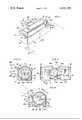
- FIG. 1is a perspective view of a housing for a battery and an ejector mechanism for partial ejection of the battery therefrom;
- FIG. 2is a vertical section as seen along the line 2--2 in FIG. 1;
- FIG. 3is a view similar to FIG. 2 illustrating the manner of ejection of the battery.
- FIG. 4is a rear elevational view of the housing and battery mechanism.
- a housing 10is illustrated in association with a casing 12 (a portion of which is shown in phantom outline) providing, for example, an enclosure for a prime mover (not shown) and a gear train (also not shown) by which through suitable gear reduction the prime mover drives the hands of a clock.
- the prime moveris powered by a source of direct current derived from a battery 14 received within a compartment 16 of the housing. Even though the prime mover may have relatively low power requirements it nevertheless at some time becomes necessary to remove the battery for replacement.
- the present inventionprovides a structure by which this action may be carried out.
- the housingis fabricated of plastic and, preferably, a plastic which is capable of being molded or otherwise formed to the outline as will be described. Additionally, the plastic should be sturdy, it should display impact resistance capability, and, among other characteristics desired of molded plastic structures of the type herein, it should have some resilience whereby a portion of an upstanding wall may define a hinge about which an ejector mechanism may pivot for partial ejection of the battery from the compartment.
- Plastic materials which are suitable for useinclude Delrin 900 and Celcon M-90, both of which have been used successfully in the practice of this invention.
- the housingincludes a pair of side walls 18, 20 and for the sake of discussion a front wall 22 and a rear wall 24, each of which extend upwardly from a bottom wall 26.
- the front wall 22includes a cutout 28 which is generally of the outline of a trapezoid whose non-parallel sides diverge outwardly from a hinge 30 at the opening to the compartment 16.
- the bottom wall 26,likewise, includes a cutout indicated at 32.
- the cutoutis of T-shape outline. To this end, the arms extend between the side walls 18, 20 and the leg communicates with the cutout 28.
- An ejector mechanism 34is supported by the hinge 30 for movement within the cutouts 28 and 32 from the position of FIG. 2 to the position of FIG. 3 when it is desired to eject the battery 14 from compartment 16.
- the ejector mechanismwhich substantially is of Z-shaped outline in vertical section, includes a lever arm 36 having a finger engageable portion, 36a and a lever arm 38 having a battery engageable portion 38a and a connecting portion 38a .
- the lever arm 36extends generally outwardly of the front wall 22 while the lever arm 38 thereof extends first generally along the length of the front wall within the cutout 28 and then along the bottom wall 26 within the cutout 32.
- a raised tip 40is formed at the end of the engageable portion 38a for contacting the battery 14.
- a pair of spines 42extend outwardly from the lever arm 38 between the engageable portion 36a and merging at the engageable portion 38a.
- a pair of ribs 44extend inwardly from the lever arm 38. The ribs are disposed laterally outward of the spines and, additionally, serve to support the battery during ejection.
- the ribs 44, a pair of ribs 46 formed on the bottom wall at spaced dispositions along cutout 32 and ribs 48 similarly formed on the bottom wall although on the opposite side of the cutoutprovide a saddle for supporting the battery in the operative disposition.
- Each of the side walls 18 and 20is formed with a slot 50 which extends between the end of the side wall at the opening to the compartment 16 and the bottom wall 26.
- the slotsare formed parallel to the surface of each side wall and communicate with the compartment by means of a cutout 52.
- a terminal 54including a base 54a received in the slot and a spring arm 54b which extends through the cutout provides connection for the battery 14 in an electric circuit.
- Each spring armfurther includes a raised rounded portion 54c which may be struck from or otherwise attached to the spring arm, for reasons as will appear.
- a battery 14is received in the compartment 16 and moved into the seated position thereby to be supported by the saddle formed by the several ribs.
- the terminals of the batterymove to a position in substantial alignment with the spring arm 54b of terminal 54.
- the battery endsare engaged by the raised rounded portions 54c and the spring bias of the arms holds the battery in the seated position.
- the engagement of the raised rounded portion particularly with the terminal extension of the batteryis within substantially the central to lower one-half.
- the housing 10When it is required to replace a worn battery 14, the individual exerts pressure on the finger engageable portion of lever arm 36.
- the housing 10may be associated with and stabilized by a casing 12 or other structure and since the plastic material has some resiliency through pressure on the lever arm 36 the hinge will undergo some degree of torsion.
- the hinge 30 adjacent the sides of the ejector mechanismmay be notched slightly at 30a. The notches may be provided on one or both sides of the front wall 22.
- the battery engageable portion of lever arm 38(FIG. 3) engages the battery, forcing the battery in the direction of arrow 56. As may be seen, this action causes the terminal extension of battery 14 to ride over the raised rounded portion 54c on the spring arm 54b of terminal 54.
Landscapes
- Chemical & Material Sciences (AREA)
- Chemical Kinetics & Catalysis (AREA)
- Electrochemistry (AREA)
- General Chemical & Material Sciences (AREA)
- Battery Mounting, Suspending (AREA)
Abstract
Description
Claims (5)
Priority Applications (1)
| Application Number | Priority Date | Filing Date | Title |
|---|---|---|---|
| US05/665,793US4031295A (en) | 1976-03-11 | 1976-03-11 | Combination housing with compartment and ejector mechanism for ejecting a battery therefrom |
Applications Claiming Priority (1)
| Application Number | Priority Date | Filing Date | Title |
|---|---|---|---|
| US05/665,793US4031295A (en) | 1976-03-11 | 1976-03-11 | Combination housing with compartment and ejector mechanism for ejecting a battery therefrom |
Publications (1)
| Publication Number | Publication Date |
|---|---|
| US4031295Atrue US4031295A (en) | 1977-06-21 |
Family
ID=24671598
Family Applications (1)
| Application Number | Title | Priority Date | Filing Date |
|---|---|---|---|
| US05/665,793Expired - LifetimeUS4031295A (en) | 1976-03-11 | 1976-03-11 | Combination housing with compartment and ejector mechanism for ejecting a battery therefrom |
Country Status (1)
| Country | Link |
|---|---|
| US (1) | US4031295A (en) |
Cited By (35)
| Publication number | Priority date | Publication date | Assignee | Title |
|---|---|---|---|---|
| US4138531A (en)* | 1977-12-27 | 1979-02-06 | Honeywell, Inc. | Battery holder for a control device |
| US4495257A (en)* | 1983-08-29 | 1985-01-22 | Memory Protection Devices, Inc. | Horizontal battery holder for cylinder cells |
| US4832610A (en)* | 1986-06-23 | 1989-05-23 | Yamaichi Electric Mfg. Co., Ltd. | IC Package extracting mechanism used in IC socket |
| FR2649805A1 (en)* | 1989-07-11 | 1991-01-18 | Asahi Optical Co Ltd | Structure for accommodating small objects |
| US5447444A (en)* | 1992-12-26 | 1995-09-05 | Yamaichi Electronics Co., Ltd. | IC socket |
| US5458499A (en)* | 1992-12-26 | 1995-10-17 | Yamaichi Electronics Co., Ltd. | IC socket |
| US5628645A (en)* | 1994-05-18 | 1997-05-13 | Yamaichi Electronics Co., Ltd. | IC socket |
| US20030124200A1 (en)* | 1999-06-22 | 2003-07-03 | Stone Kevin R. | Cartilage enhancing food supplements with sucralose and methods of preparing the same |
| US20040001997A1 (en)* | 2002-06-27 | 2004-01-01 | Vocollect, Inc. | Wearable terminal |
| US20040106314A1 (en)* | 2002-10-21 | 2004-06-03 | Yu-Yuan Chen | Portable apparatus with inward-pushing triggered mechanism for ejecting add-on device |
| US20070080930A1 (en)* | 2005-10-11 | 2007-04-12 | Logan James R | Terminal device for voice-directed work and information exchange |
| US20070183616A1 (en)* | 2006-02-06 | 2007-08-09 | James Wahl | Headset terminal with rear stability strap |
| US20070243457A1 (en)* | 2006-04-12 | 2007-10-18 | Andres Viduya | Electronic device with multiple battery contacts |
| US7291027B1 (en)* | 2006-07-25 | 2007-11-06 | D-Link Corporation | External box for hard disk drives with quick release mechanism |
| USD558761S1 (en) | 2005-09-19 | 2008-01-01 | Vocollect, Inc. | Portable processing terminal |
| US20080033248A1 (en)* | 2005-02-17 | 2008-02-07 | Toshimasa Akagi | Portable Electronic Device And Capsule Endoscope Diagnosis System |
| USD567219S1 (en) | 2005-11-15 | 2008-04-22 | Vocollect, Inc. | Headset |
| USD567218S1 (en) | 2005-11-16 | 2008-04-22 | Vocollect, Inc. | Control panel for a headset |
| USD605629S1 (en) | 2008-09-29 | 2009-12-08 | Vocollect, Inc. | Headset |
| US20100099017A1 (en)* | 2008-10-20 | 2010-04-22 | Fih (Hong Kong) Limited | Battery holding mechanism and portable electronic device using the same |
| USD626949S1 (en) | 2008-02-20 | 2010-11-09 | Vocollect Healthcare Systems, Inc. | Body-worn mobile device |
| US20110026200A1 (en)* | 2009-07-31 | 2011-02-03 | Shenzhen Futaihong Precision Industry Co., Ltd. | Battery ejector and electronic device using the same |
| US7885419B2 (en) | 2006-02-06 | 2011-02-08 | Vocollect, Inc. | Headset terminal with speech functionality |
| CN101990014A (en)* | 2009-08-04 | 2011-03-23 | 深圳富泰宏精密工业有限公司 | Battery ejection device and portable electronic device with same |
| US20110107415A1 (en)* | 2009-11-05 | 2011-05-05 | Yangmin Shen | Portable computing device and headset interface |
| USD643013S1 (en) | 2010-08-20 | 2011-08-09 | Vocollect Healthcare Systems, Inc. | Body-worn mobile device |
| USD643400S1 (en) | 2010-08-19 | 2011-08-16 | Vocollect Healthcare Systems, Inc. | Body-worn mobile device |
| US8128422B2 (en) | 2002-06-27 | 2012-03-06 | Vocollect, Inc. | Voice-directed portable terminals for wireless communication systems |
| US8160287B2 (en) | 2009-05-22 | 2012-04-17 | Vocollect, Inc. | Headset with adjustable headband |
| US8386261B2 (en) | 2008-11-14 | 2013-02-26 | Vocollect Healthcare Systems, Inc. | Training/coaching system for a voice-enabled work environment |
| US8417185B2 (en) | 2005-12-16 | 2013-04-09 | Vocollect, Inc. | Wireless headset and method for robust voice data communication |
| US8659397B2 (en) | 2010-07-22 | 2014-02-25 | Vocollect, Inc. | Method and system for correctly identifying specific RFID tags |
| CN105098110A (en)* | 2014-05-23 | 2015-11-25 | 国基电子(上海)有限公司 | Battery installing device |
| US20180183022A1 (en)* | 2016-12-27 | 2018-06-28 | Samsung Electronics Co., Ltd. | Battery case and remote controller including the same |
| CN112838317A (en)* | 2019-11-07 | 2021-05-25 | 台达电子工业股份有限公司 | Battery box structure |
Citations (4)
| Publication number | Priority date | Publication date | Assignee | Title |
|---|---|---|---|---|
| SU180640A1 (en)* | Н. А. Исупов Сарапульский радиозавод Орджоникидзе | |||
| US2430707A (en)* | 1944-09-21 | 1947-11-11 | Us Playing Card Co | Receptacle with lid-operated lifter |
| US3181974A (en)* | 1962-05-16 | 1965-05-04 | Barb Inc | Releasable battery clip |
| US3445297A (en)* | 1967-06-05 | 1969-05-20 | Ingraham & Co | Battery ejector for portable appliances |
- 1976
- 1976-03-11USUS05/665,793patent/US4031295A/ennot_activeExpired - Lifetime
Patent Citations (4)
| Publication number | Priority date | Publication date | Assignee | Title |
|---|---|---|---|---|
| SU180640A1 (en)* | Н. А. Исупов Сарапульский радиозавод Орджоникидзе | |||
| US2430707A (en)* | 1944-09-21 | 1947-11-11 | Us Playing Card Co | Receptacle with lid-operated lifter |
| US3181974A (en)* | 1962-05-16 | 1965-05-04 | Barb Inc | Releasable battery clip |
| US3445297A (en)* | 1967-06-05 | 1969-05-20 | Ingraham & Co | Battery ejector for portable appliances |
Cited By (60)
| Publication number | Priority date | Publication date | Assignee | Title |
|---|---|---|---|---|
| US4138531A (en)* | 1977-12-27 | 1979-02-06 | Honeywell, Inc. | Battery holder for a control device |
| US4495257A (en)* | 1983-08-29 | 1985-01-22 | Memory Protection Devices, Inc. | Horizontal battery holder for cylinder cells |
| US4832610A (en)* | 1986-06-23 | 1989-05-23 | Yamaichi Electric Mfg. Co., Ltd. | IC Package extracting mechanism used in IC socket |
| FR2649805A1 (en)* | 1989-07-11 | 1991-01-18 | Asahi Optical Co Ltd | Structure for accommodating small objects |
| US5077572A (en)* | 1989-07-11 | 1991-12-31 | Asahi Kogaku Kogyo Kabushiki Kaisha | Housing structure for backup battery |
| US5447444A (en)* | 1992-12-26 | 1995-09-05 | Yamaichi Electronics Co., Ltd. | IC socket |
| US5458499A (en)* | 1992-12-26 | 1995-10-17 | Yamaichi Electronics Co., Ltd. | IC socket |
| US5628645A (en)* | 1994-05-18 | 1997-05-13 | Yamaichi Electronics Co., Ltd. | IC socket |
| US20030124200A1 (en)* | 1999-06-22 | 2003-07-03 | Stone Kevin R. | Cartilage enhancing food supplements with sucralose and methods of preparing the same |
| US20050272401A1 (en)* | 2002-06-27 | 2005-12-08 | Vocollect, Inc. | Environmentally-sealed portable terminal |
| US20040001997A1 (en)* | 2002-06-27 | 2004-01-01 | Vocollect, Inc. | Wearable terminal |
| US7052799B2 (en) | 2002-06-27 | 2006-05-30 | Vocollect, Inc. | Wearable terminal with a battery latch mechanism |
| US8128422B2 (en) | 2002-06-27 | 2012-03-06 | Vocollect, Inc. | Voice-directed portable terminals for wireless communication systems |
| US20040106314A1 (en)* | 2002-10-21 | 2004-06-03 | Yu-Yuan Chen | Portable apparatus with inward-pushing triggered mechanism for ejecting add-on device |
| US6796819B2 (en)* | 2002-10-21 | 2004-09-28 | Benq Corporation | Portable apparatus with inward-pushing triggered mechanism for ejecting add-on device |
| US20080033248A1 (en)* | 2005-02-17 | 2008-02-07 | Toshimasa Akagi | Portable Electronic Device And Capsule Endoscope Diagnosis System |
| US8372001B2 (en)* | 2005-02-17 | 2013-02-12 | Olympus Medical Systems Corp. | Portable electronic device and capsule endoscope diagnosis system |
| USD565569S1 (en) | 2005-09-19 | 2008-04-01 | Vocollect, Inc. | Portable processing terminal |
| USD558761S1 (en) | 2005-09-19 | 2008-01-01 | Vocollect, Inc. | Portable processing terminal |
| US20070080930A1 (en)* | 2005-10-11 | 2007-04-12 | Logan James R | Terminal device for voice-directed work and information exchange |
| USD567799S1 (en) | 2005-11-15 | 2008-04-29 | Vocollect, Inc. | Headset |
| USD567219S1 (en) | 2005-11-15 | 2008-04-22 | Vocollect, Inc. | Headset |
| USD567806S1 (en) | 2005-11-15 | 2008-04-29 | Vocollect, Inc. | Headset |
| USD567218S1 (en) | 2005-11-16 | 2008-04-22 | Vocollect, Inc. | Control panel for a headset |
| US8417185B2 (en) | 2005-12-16 | 2013-04-09 | Vocollect, Inc. | Wireless headset and method for robust voice data communication |
| US7885419B2 (en) | 2006-02-06 | 2011-02-08 | Vocollect, Inc. | Headset terminal with speech functionality |
| US8842849B2 (en) | 2006-02-06 | 2014-09-23 | Vocollect, Inc. | Headset terminal with speech functionality |
| US20070223766A1 (en)* | 2006-02-06 | 2007-09-27 | Michael Davis | Headset terminal with rear stability strap |
| US7773767B2 (en) | 2006-02-06 | 2010-08-10 | Vocollect, Inc. | Headset terminal with rear stability strap |
| US20070183616A1 (en)* | 2006-02-06 | 2007-08-09 | James Wahl | Headset terminal with rear stability strap |
| US20110116672A1 (en)* | 2006-02-06 | 2011-05-19 | James Wahl | Headset terminal with speech functionality |
| US20070243457A1 (en)* | 2006-04-12 | 2007-10-18 | Andres Viduya | Electronic device with multiple battery contacts |
| US7291027B1 (en)* | 2006-07-25 | 2007-11-06 | D-Link Corporation | External box for hard disk drives with quick release mechanism |
| USD626949S1 (en) | 2008-02-20 | 2010-11-09 | Vocollect Healthcare Systems, Inc. | Body-worn mobile device |
| USD613267S1 (en) | 2008-09-29 | 2010-04-06 | Vocollect, Inc. | Headset |
| USD605629S1 (en) | 2008-09-29 | 2009-12-08 | Vocollect, Inc. | Headset |
| USD616419S1 (en) | 2008-09-29 | 2010-05-25 | Vocollect, Inc. | Headset |
| US8216710B2 (en)* | 2008-10-20 | 2012-07-10 | Fih (Hong Kong) Limited | Battery holding mechanism and portable electronic device using the same |
| US20100099017A1 (en)* | 2008-10-20 | 2010-04-22 | Fih (Hong Kong) Limited | Battery holding mechanism and portable electronic device using the same |
| US8386261B2 (en) | 2008-11-14 | 2013-02-26 | Vocollect Healthcare Systems, Inc. | Training/coaching system for a voice-enabled work environment |
| US8160287B2 (en) | 2009-05-22 | 2012-04-17 | Vocollect, Inc. | Headset with adjustable headband |
| US20110026200A1 (en)* | 2009-07-31 | 2011-02-03 | Shenzhen Futaihong Precision Industry Co., Ltd. | Battery ejector and electronic device using the same |
| US8199467B2 (en)* | 2009-07-31 | 2012-06-12 | Shenzhen Futaihong Precision Industry Co., Ltd. | Battery ejector and electronic device using the same |
| CN101990014B (en)* | 2009-08-04 | 2014-10-22 | 赛恩倍吉科技顾问(深圳)有限公司 | Battery ejection device and portable electronic device with same |
| CN101990014A (en)* | 2009-08-04 | 2011-03-23 | 深圳富泰宏精密工业有限公司 | Battery ejection device and portable electronic device with same |
| US8438659B2 (en) | 2009-11-05 | 2013-05-07 | Vocollect, Inc. | Portable computing device and headset interface |
| US20110107415A1 (en)* | 2009-11-05 | 2011-05-05 | Yangmin Shen | Portable computing device and headset interface |
| US9449205B2 (en) | 2010-07-22 | 2016-09-20 | Vocollect, Inc. | Method and system for correctly identifying specific RFID tags |
| US8659397B2 (en) | 2010-07-22 | 2014-02-25 | Vocollect, Inc. | Method and system for correctly identifying specific RFID tags |
| US8933791B2 (en) | 2010-07-22 | 2015-01-13 | Vocollect, Inc. | Method and system for correctly identifying specific RFID tags |
| US10108824B2 (en) | 2010-07-22 | 2018-10-23 | Vocollect, Inc. | Method and system for correctly identifying specific RFID tags |
| USD643400S1 (en) | 2010-08-19 | 2011-08-16 | Vocollect Healthcare Systems, Inc. | Body-worn mobile device |
| USD643013S1 (en) | 2010-08-20 | 2011-08-09 | Vocollect Healthcare Systems, Inc. | Body-worn mobile device |
| CN105098110A (en)* | 2014-05-23 | 2015-11-25 | 国基电子(上海)有限公司 | Battery installing device |
| US10109828B2 (en) | 2014-05-23 | 2018-10-23 | Ambit Microsystems (Shanghai) Ltd. | Housing and electronic device with mounting structure for mounting battery |
| US20180183022A1 (en)* | 2016-12-27 | 2018-06-28 | Samsung Electronics Co., Ltd. | Battery case and remote controller including the same |
| WO2018124559A1 (en) | 2016-12-27 | 2018-07-05 | Samsung Electronics Co., Ltd. | Battery case and remote controller including the same |
| EP3545567A4 (en)* | 2016-12-27 | 2020-01-08 | Samsung Electronics Co., Ltd. | BATTERY HOUSING AND REMOTE CONTROL WITH IT |
| US10700315B2 (en)* | 2016-12-27 | 2020-06-30 | Samsung Electronics Co., Ltd. | Battery case and remote controller including the same |
| CN112838317A (en)* | 2019-11-07 | 2021-05-25 | 台达电子工业股份有限公司 | Battery box structure |
Similar Documents
| Publication | Publication Date | Title |
|---|---|---|
| US4031295A (en) | Combination housing with compartment and ejector mechanism for ejecting a battery therefrom | |
| US5590475A (en) | Hand held appliance and holder assembly | |
| US6511770B2 (en) | Battery casing with an ejector | |
| US4150481A (en) | Finger-toe nail clipper having shifting receptacle | |
| EP0762520B1 (en) | Battery retention latch | |
| US4401233A (en) | Dispenser for sheets of paper and the like | |
| US4252455A (en) | Shaving brush attachment | |
| GR3005229T3 (en) | ||
| US4380869A (en) | Electric shaver of reciprocating drive type having trimmer blade | |
| AU607887B2 (en) | Wheel-type vacuum cleaner | |
| US4291207A (en) | Removable push-to-unlock actuator for locking pivoted-subactuator self-enclosed electric switch | |
| JP4018022B2 (en) | Opening and closing handle device | |
| JPS5946589B2 (en) | ashtray device | |
| WO1995003642A1 (en) | A latching system | |
| KR100414515B1 (en) | Electric Shaver | |
| JPS63129933A (en) | Pruner | |
| JP3142936B2 (en) | Rechargeable gardening clippers | |
| JPH058946Y2 (en) | ||
| JPH0238692Y2 (en) | ||
| JPH0236453Y2 (en) | ||
| KR200217597Y1 (en) | nail clipper | |
| JPS612886A (en) | Electromotive razor | |
| KR960005958Y1 (en) | Walkie talkie | |
| JPS6321090A (en) | Electric razor | |
| JPH0433654Y2 (en) |
Legal Events
| Date | Code | Title | Description |
|---|---|---|---|
| AS | Assignment | Owner name:MARINE MIDLAND BUSINESS LOANS, INC., GEORGIA Free format text:SECURITY INTEREST;ASSIGNOR:GENERAL TIME CORPORATION, F/K/A TIME ACQUISITION CORP. A CORP. OF DELAWARE;REEL/FRAME:005092/0512 Effective date:19880330 | |
| AS | Assignment | Owner name:GENERAL TIME CORPORATION, GEORGIA Free format text:ASSIGNMENT OF ASSIGNORS INTEREST.;ASSIGNOR:TALLEY INTERNATIONAL INVESTMENT CORPORATION;REEL/FRAME:005178/0666 Effective date:19890405 | |
| AS | Assignment | Owner name:BARCLAYS BUSINESS CREDIT, INC., A CORPORATION OF C Free format text:SECURITY INTEREST;ASSIGNOR:GENERAL TIME CORPORATION, A CORP. OF DE;REEL/FRAME:005648/0024 Effective date:19901105 | |
| AS | Assignment | Owner name:GENERAL TIME CORPORATION, NORCROSS, GA A CORP. OF Free format text:RELEASED BY SECURED PARTY;ASSIGNOR:MARINE MIDLAND BUSINESS LOANS, INC., A CORP. OF DE;REEL/FRAME:005665/0004 Effective date:19901105 |