US4027229A - Regulatable permanent magnet alternator - Google Patents
Regulatable permanent magnet alternatorDownload PDFInfo
- Publication number
- US4027229A US4027229AUS05/640,768US64076875AUS4027229AUS 4027229 AUS4027229 AUS 4027229AUS 64076875 AUS64076875 AUS 64076875AUS 4027229 AUS4027229 AUS 4027229A
- Authority
- US
- United States
- Prior art keywords
- alternator
- sleeve
- poles
- stator
- end plate
- Prior art date
- Legal status (The legal status is an assumption and is not a legal conclusion. Google has not performed a legal analysis and makes no representation as to the accuracy of the status listed.)
- Expired - Lifetime
Links
- 230000004907fluxEffects0.000claimsabstractdescription15
- 238000004804windingMethods0.000claimsabstractdescription7
- 238000003475laminationMethods0.000claimsdescription9
- 239000011810insulating materialSubstances0.000claimsdescription7
- 125000006850spacer groupChemical group0.000claimsdescription7
- 229910052751metalInorganic materials0.000claimsdescription5
- 239000002184metalSubstances0.000claimsdescription4
- 239000003302ferromagnetic materialSubstances0.000claimsdescription3
- 230000005291magnetic effectEffects0.000claims1
- 230000001105regulatory effectEffects0.000abstractdescription6
- 230000005294ferromagnetic effectEffects0.000abstractdescription3
- 150000001875compoundsChemical class0.000description4
- 239000000463materialSubstances0.000description3
- 238000010276constructionMethods0.000description2
- 238000000926separation methodMethods0.000description2
- RYGMFSIKBFXOCR-UHFFFAOYSA-NCopperChemical compound[Cu]RYGMFSIKBFXOCR-UHFFFAOYSA-N0.000description1
- 229910000831SteelInorganic materials0.000description1
- 230000000903blocking effectEffects0.000description1
- 229910052802copperInorganic materials0.000description1
- 239000010949copperSubstances0.000description1
- 238000009434installationMethods0.000description1
- 239000007769metal materialSubstances0.000description1
- 238000000034methodMethods0.000description1
- 238000004382pottingMethods0.000description1
- 239000007787solidSubstances0.000description1
- 239000010959steelSubstances0.000description1
Images

Classifications
- H—ELECTRICITY
- H02—GENERATION; CONVERSION OR DISTRIBUTION OF ELECTRIC POWER
- H02K—DYNAMO-ELECTRIC MACHINES
- H02K21/00—Synchronous motors having permanent magnets; Synchronous generators having permanent magnets
- H02K21/02—Details
- H02K21/021—Means for mechanical adjustment of the excitation flux
- H02K21/028—Means for mechanical adjustment of the excitation flux by modifying the magnetic circuit within the field or the armature, e.g. by using shunts, by adjusting the magnets position, by vectorial combination of field or armature sections
- H—ELECTRICITY
- H02—GENERATION; CONVERSION OR DISTRIBUTION OF ELECTRIC POWER
- H02K—DYNAMO-ELECTRIC MACHINES
- H02K21/00—Synchronous motors having permanent magnets; Synchronous generators having permanent magnets
- H02K21/12—Synchronous motors having permanent magnets; Synchronous generators having permanent magnets with stationary armatures and rotating magnets
- H02K21/14—Synchronous motors having permanent magnets; Synchronous generators having permanent magnets with stationary armatures and rotating magnets with magnets rotating within the armatures
- H02K21/16—Synchronous motors having permanent magnets; Synchronous generators having permanent magnets with stationary armatures and rotating magnets with magnets rotating within the armatures having annular armature cores with salient poles
Definitions
- a method of assembling the sleeveincludes the steps of assembling the stacks, rivets and end plates. Thereafter, that assembly is placed in a jig between an external cylinder and an internal cylinder and the spaces between the stacks are filled with molten plastic material (potting compound). This material is allowed to cool and harden. Each stack is provided on its opposite faces with grooves so that the hardened plastic spacers are keyed to the stacks of laminations.
- molten plastic materialpotting compound
- the alternatoris mounted on a base plate 1 adapted for mounting on an engine (not shown), and includes a stator generally indicated at 2, a rotor 3 and a flux regulating sleeve 4.
- End plates 12 and 13 of insulating materialextend across the two ends of the members 11.
- Another end plate 14, of metal, preferably steel,extends across one end only of the members 11.
- Each memberis held between the end plates by a rivet 15 having an elongated shank and two heads 15a and 15b.
- the shank of each rivet 15is encircled by a tube 16 of insulating material, which is effective to prevent short circuits or eddy currents between the laminations through the shank of rivet 15.
Landscapes
- Engineering & Computer Science (AREA)
- Power Engineering (AREA)
- Iron Core Of Rotating Electric Machines (AREA)
- Permanent Magnet Type Synchronous Machine (AREA)
Abstract
Description
The alternator of the invention comprises a rotor member and a stator member, each with projecting poles. One of the two members carries an armature winding and the other carries a permanent magnet field. A sleeve for regulating the flux linkage between the field and the armature winding is positioned between the stator and rotor. The sleeve comprises a plurality of peripherally spaced stacks of laminations of ferromagnetic material. The number of stacks is equal to the number of poles on the armature. The field may have the same number of poles, or may have less. The sleeve also includes two end plates, one at each end of the sleeve. A plurality of rivets holds the sleeve together, one rivet extending through each stack and both end plates. Both ends of the stack have end plates of insulating material. One end of the stack also has a second end plate of metal, which is connected to a motor for positioning the sleeve and thereby regulating the alternator output. The rotor is supported on a shaft extending within the sleeve. The sleeve is journaled in a pair of bearing means located at opposite ends of the sleeve.
A method of assembling the sleeve is disclosed and includes the steps of assembling the stacks, rivets and end plates. Thereafter, that assembly is placed in a jig between an external cylinder and an internal cylinder and the spaces between the stacks are filled with molten plastic material (potting compound). This material is allowed to cool and harden. Each stack is provided on its opposite faces with grooves so that the hardened plastic spacers are keyed to the stacks of laminations.
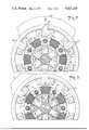
FIG. 1 is a cross-sectional view through a regulatable permanent magnet alternator according to the invention.
FIG. 2 is a fragmentary cross-sectional view online 2--2 of FIG. 1 on an enlarged scale, showing the sleeve in its maximum flux linkage position.
FIG. 3 is a view similar to FIG. 2, showing the sleeve in its minimum flux position.
FIG. 4 is an elevational view of the flux regulating sleeve, partially broken away.
FIG. 5 is a view taken on theline 5--5 of FIG. 4.
The alternator is mounted on abase plate 1 adapted for mounting on an engine (not shown), and includes a stator generally indicated at 2, a rotor 3 and aflux regulating sleeve 4.
Thestator 2 serves as an armature in the embodiment illustrated, and is clamped between thebase plate 1 and anopposite end plate 25. Ashaft 6 extends from the engine throughbase plate 1 and theend plate 25 and is journaled in bearings in thebase plate 1 and ajournal plate 26. Acover plate 27 is mounted outside theplate 26. Theplates bolts 28.
Thestator 2 comprises a stack of laminations including anannulus 2a with inwardly projectingpoles 2b. An armature winding comprises a plurality ofcoils 5, one encircling each of the projectingpoles 2b. Note that thepoles 2b are straight-sided, i.e., they have no flared or projecting inner ends as is conventional in machines of this type. The flared or projecting ends may be used in an alternator constructed in accordance with the invention, but they are not necessary. Their omission greatly facilitates the assembly of thecoils 5 on thepoles 2b, since the coils can be preformed, slid over the projecting poles and bonded in place. Furthermore, the internal dimensions of thecoils 5 may be made the same as the dimensions ofpoles 2b, thereby making more space for copper in thecoils 5, than is available in alternators of conventional construction. The rotor 3 has at least one pair of radially outwardly projecting poles 3a, of alternating polarities. It is shown as having three pairs of poles. When thearmature 2 has a polyphase winding, the number of poles on the field must be less than the number of poles on the armature. The number ofbridging members 11 on the sleeve is still the same as the number of poles on the armature stator. The details of construction of the rotor 3 are not illustrated, and may be similar to those shown in the patent to Knudson et al, U.S. Pat. No. 3,508,095. The rotor 3 is fixed on theshaft 6.
Thesleeve 4 comprises a plurality of axially extendingferromagnetic bridging members 11, each comprising amiddle stack 11a of laminations of ferromagnetic material, and end extensions 11b, 11c.
Themembers 11 should be as long or longer than the stacks of laminations in thestator 2. Themembers 11 may extend beyond the laminations of thestator 2 in order that itsbearings spacers 17 described below.
A pair ofbearing rings plates sleeve 4. Thesleeve 4 is driven through a limited angle about theshaft 6 by means of a pair ofbolts 31 fixed in theend plates slots 26a in thejournal plate 26 to adrive plate 32 driven by amotor 20 received in thecover 27.
When thesleeve 4 is in the angular position shown in FIG. 2, themembers 11 are aligned with thestator poles 2b, and the flux path of lowest reluctance from one permanent magnet pole 3a to the next is through the alignedmembers 11, thepoles 2b and theannulus 2a, as shown at 23 in FIG. 2. The flux through the path just described is at a maximum when the rotor 3 is in the angular position shown. As the rotor turns, the rate of change of flux through thearmature coils 5 is at a maximum, and the alternator output is at its maximum.
When the sleeve is moved to the angular position of FIG. 3, where themembers 11 are aligned with the spaces between thepoles 2b, the path of lowest reluctance from one permanent magnet pole 3a to the next is directly through theadjacent member 11, which bridges the space between the ends of the rotor poles. This minimum reluctance path is shown at 24 in FIG. 3. Most of the rotor flux is thereby shunted away from the rotor poles 3a. As the rotor turns, the rate of change of flux through thearmature coils 5 is at a minimum and the alternator output is at its minimum.
Themembers 11 are separated by an angle equal to the separation between two stator poles. Hence, thesleeve 4 need only rotate through ninety electrical degrees, i.e., an angle equal to one half of the pole separation angle in order to shift the alternator between its minimum output condition and its maximum output condition. Themotor 20 may be either a two-position type or a proportioning type. A two-position type may be defined as one which holds thesleeve 4 either in the position of FIG. 2 or the position of FIG. 3. A proportioning type may be defined as one which would hold the sleeve in either of those positions or move it to any intermediate position, depending upon the requirements of the installation.
Theflux regulating sleeve 4 may be assembled by first assembling theend plates rivets 15, thetubes 16, and themembers 11. Theend plate 13 is then placed over the other end of the members, and the heads 15b of the rivets are peened over to hold the assembly together. This assembly is then placed in a jig with an external cylinder enclosing the sleeve and an internal cylinder blocking the space inside the sleeve. The spaces betweenmembers 11 are then filled with a molten plastic compound which is allowed to cool and harden, thereby forming rigid insulatingspacers 17 between themembers 11. Eachmember 11 is provided with a pair ofrecesses 11d on its opposite radially extending faces, so that when the insulating compound has hardened, eachspacer 17 is keyed to both theadjacent stacks 11 by the compound which has flowed into therecesses 11a.
Note that themembers 11 have a longer circumferential extent than the ends of thepoles 2b. Hence they serve to direct the flux through thepoles 2b, even when they are somewhat misaligned from those poles.
Claims (10)
1. A regulatable permanent magnet alternator, including:
(a) a stator member having at least one pair of poles;
(b) a rotor member having at least one pair of poles;
(c) permanent magnet field means on one of said members;
(d) armature winding means on the other of said members;
(e) a hollow cylindrical sleeve coaxial with the rotor member and extending between the stator member and rotor member, said sleeve comprising:
(1) a plurality of peripherally spaced bridging members, each bridging member including a stack of laminations of ferromagnetic material, said bridging members being equal in number to the number of stator poles;
(2) two end plate means, one at each end of said sleeve;
(3) a plurality of fastening means, each including a rod extending through one of the bridging members and both end plate means; and
(f) means operatively connected to the sleeve for shifting the angular position thereof to change the alignment of the bridging members with respect to the stator poles, and thereby the magnetic flux linkage between the field means and the armature winding means.
2. An alternator as in claim 1, including an insulating tube extending between each bridging member and its associated rod.
3. An alternator as in claim 1, in which said sleeve is axially longer than the stator and rotor poles.
4. An alternator as in claim 1, in which:
(a) each of said end plate means comprises a plate of insulating material;
(b) one of said end plate means further comprises a metal end plate; and
(c) said motor means is drivingly connected to said metal end plate.
5. An alternator as in claim 1, including spacers of insulating material between said stacks of laminations and keyed to said stacks.
6. An alternator as in claim 1, including:
(a) a housing supporting said stator member;
(b) a pair of support means spaced from opposite ends of the stator member and supporting said sleeve; and
(c) means in one end of said housing supporting said shifting means.
7. An alternator as in claim 6, in which each support means includes a bearing receiving one of said end plate means.
8. An alternator as in claim 1, in which the poles of said other member have flat radially and axially extending sides.
9. An alternator as in claim 1, including a plurality of spacers of insulating material, equal in number to said bridging members, each located between two of said bridging members.
10. An alternator as in claim 9, in which each spacer is keyed to the two adjacent bridging members.
Priority Applications (6)
| Application Number | Priority Date | Filing Date | Title |
|---|---|---|---|
| US05/640,768US4027229A (en) | 1975-12-15 | 1975-12-15 | Regulatable permanent magnet alternator |
| GB49606/76AGB1545227A (en) | 1975-12-15 | 1976-11-29 | Regulatable permanent magnet alternator |
| JP51144605AJPS5280410A (en) | 1975-12-15 | 1976-12-01 | Adjustable permanent magnet synchronous generator |
| DE19762654812DE2654812A1 (en) | 1975-12-15 | 1976-12-03 | PERMANENT MAGNET AC GENERATOR |
| FR7637073AFR2335986A1 (en) | 1975-12-15 | 1976-12-09 | PERMANENT MAGNET ALTERNATOR, ADJUSTABLE |
| CA267,897ACA1060523A (en) | 1975-12-15 | 1976-12-14 | Regulatable permanent magnet alternator |
Applications Claiming Priority (1)
| Application Number | Priority Date | Filing Date | Title |
|---|---|---|---|
| US05/640,768US4027229A (en) | 1975-12-15 | 1975-12-15 | Regulatable permanent magnet alternator |
Publications (1)
| Publication Number | Publication Date |
|---|---|
| US4027229Atrue US4027229A (en) | 1977-05-31 |
Family
ID=24569630
Family Applications (1)
| Application Number | Title | Priority Date | Filing Date |
|---|---|---|---|
| US05/640,768Expired - LifetimeUS4027229A (en) | 1975-12-15 | 1975-12-15 | Regulatable permanent magnet alternator |
Country Status (6)
| Country | Link |
|---|---|
| US (1) | US4027229A (en) |
| JP (1) | JPS5280410A (en) |
| CA (1) | CA1060523A (en) |
| DE (1) | DE2654812A1 (en) |
| FR (1) | FR2335986A1 (en) |
| GB (1) | GB1545227A (en) |
Cited By (32)
| Publication number | Priority date | Publication date | Assignee | Title |
|---|---|---|---|---|
| US4100382A (en)* | 1976-07-30 | 1978-07-11 | Canadian General Electric Co., Ltd. | Permanent magnet latch for speed switching device |
| US4286181A (en)* | 1979-07-12 | 1981-08-25 | International Business Machines Corporation | Stepping motor for rotary device |
| US4578609A (en)* | 1982-09-29 | 1986-03-25 | The Garrett Corporation | Permanent magnet dynamoelectric machine |
| US4766362A (en)* | 1986-11-24 | 1988-08-23 | Simmonds Precision Products, Inc. | Regulatable permanent magnet alternator |
| US4885493A (en)* | 1988-07-25 | 1989-12-05 | General Motors Corporation | Output voltage control apparatus of a permanent magnet alternator |
| DE4137457C1 (en)* | 1991-11-14 | 1993-01-21 | Dornier Gmbh, 7990 Friedrichshafen, De | Voltage regulator for permanent magnet generator - reduces flux density by iris diaphragm closure and lowers generator voltage for stable supply |
| US5191258A (en)* | 1991-09-11 | 1993-03-02 | German James W | Electric current generator including torque reducing countermagnetic field |
| WO2001065669A1 (en)* | 2000-03-02 | 2001-09-07 | Motorenfabrik Hatz Gmbh & Co. Kg | Power generating installation that comprises a generator and a reciprocating internal combustion engine as drive |
| US6495941B1 (en)* | 2000-05-18 | 2002-12-17 | Mitsubishi Denki Kabushiki Kaisha | Dynamo-electric machine |
| US6504281B1 (en)* | 2000-07-12 | 2003-01-07 | Electric Boat Corporation | Synchronous machine fault tolerant arrangement |
| US6690145B2 (en) | 2002-04-01 | 2004-02-10 | E-Tec Corporation | Permanent magnet alternator and voltage regulator circuit for the permanent magnet alternator |
| US20040212273A1 (en)* | 2003-04-24 | 2004-10-28 | Gould Len Charles | Heat engine and generator set incorporating multiple generators for synchronizing and balancing |
| US20040257832A1 (en)* | 2003-01-23 | 2004-12-23 | Skeist S. Merrill | Permanent magnet induction machine |
| EP1750357A1 (en)* | 2005-08-05 | 2007-02-07 | Yamaha Hatsudoki Kabushiki Kaisha | Saddle-type vehicle provided with rotary electric machine |
| EP1750356A1 (en)* | 2005-08-05 | 2007-02-07 | Yamaha Hatsudoki Kabushiki Kaisha | Stator for rotary electric machine |
| WO2007095254A1 (en)* | 2006-02-10 | 2007-08-23 | The Timken Company | Electric motor with field weakening |
| US20070210666A1 (en)* | 2006-03-09 | 2007-09-13 | Mitsubishi Electric Corporation | Electric rotating machine |
| USRE40320E1 (en) | 2001-04-02 | 2008-05-20 | E-Tech Corporation | Permanent magnet alternator and voltage regulator circuit for the permanent magnet alternator |
| US20080136294A1 (en)* | 2006-12-06 | 2008-06-12 | Hamilton Sundstrand Corporation | Self-regulating permanent magnet device |
| US20090045765A1 (en)* | 2007-08-17 | 2009-02-19 | Kura Laboratory Corporation | Field controllable rotating electric machine system with magnetic excitation part |
| CN1909335B (en)* | 2005-08-05 | 2010-04-07 | 雅马哈发动机株式会社 | Rotary electric machine |
| US20110215667A1 (en)* | 2010-03-03 | 2011-09-08 | Industrial Technology Research Institute | Magnetic transmission assembly |
| US20110215668A1 (en)* | 2010-03-03 | 2011-09-08 | Industrial Technology Research Institute | Magnetic transmission assembly |
| FR3026577A1 (en)* | 2014-09-26 | 2016-04-01 | Thierry Lucidarme | ELECTRICAL MACHINE WITHOUT DOUBLE ROTOR CONTACTS |
| EP3054562A1 (en)* | 2015-02-09 | 2016-08-10 | Siemens Aktiengesellschaft | Electric drive machine |
| US9479037B2 (en) | 2014-08-01 | 2016-10-25 | Falcon Power, LLC | Variable torque motor/generator/transmission |
| US20160329784A1 (en)* | 2014-02-20 | 2016-11-10 | Mitsubishi Electric Corporation | Rotor, permanent magnet electric motor having the rotor, fluid machine having the permanent magnet electric motor, and method for manufacturing the rotor |
| CN110462998A (en)* | 2017-02-17 | 2019-11-15 | 到达有限公司 | Motor |
| US11296638B2 (en) | 2014-08-01 | 2022-04-05 | Falcon Power, LLC | Variable torque motor/generator/transmission |
| GB2623174A (en)* | 2022-10-05 | 2024-04-10 | Porsche Ag | Electric machine and motor vehicle |
| GB2623173A (en)* | 2022-10-05 | 2024-04-10 | Porsche Ag | Electric machine, method for operating said machine, and motor vehicle |
| US20240250569A1 (en)* | 2023-01-24 | 2024-07-25 | GM Global Technology Operations LLC | Stabilized core assembly for carbon fiber sleeved electric motor rotor |
Families Citing this family (9)
| Publication number | Priority date | Publication date | Assignee | Title |
|---|---|---|---|---|
| GB8531212D0 (en)* | 1985-12-18 | 1986-01-29 | Lynch C | Electrical machines |
| DE4421594A1 (en)* | 1994-06-21 | 1996-01-04 | Bernhard Kraser | Air-gap induction variation device for rotary or linear electrical machine |
| US5763977A (en)* | 1995-07-21 | 1998-06-09 | Honda Giken Kogyo Kabushiki Kaisha | Motor vehicle alternator and system for controlling the same |
| EP2592732A1 (en)* | 2004-02-06 | 2013-05-15 | Yamaha Hatsudoki Kabushiki Kaisha | Electrically driven vehicle |
| ES2768324T3 (en)* | 2004-02-06 | 2020-06-22 | Yamaha Motor Co Ltd | Vehicle |
| WO2009013934A1 (en)* | 2007-07-26 | 2009-01-29 | Kura Laboratory Corporation | Flux shunt control rotary electric machine system |
| WO2009025110A1 (en)* | 2007-08-17 | 2009-02-26 | Kura Laboratory Corporation | Magnetic flux distribution control type rotary electrical machine system |
| US20110101817A1 (en)* | 2009-11-05 | 2011-05-05 | Gm Global Technology Operations, Inc. | Variable geometry electric machine |
| JP2014068496A (en)* | 2012-09-27 | 2014-04-17 | Hitachi Automotive Systems Ltd | On-vehicle rotary electric machine |
Citations (6)
| Publication number | Priority date | Publication date | Assignee | Title |
|---|---|---|---|---|
| US2610993A (en)* | 1951-07-12 | 1952-09-16 | Gen Electric | Adjustable magnetic shunt for permanent magnet generators |
| US2807772A (en)* | 1954-08-27 | 1957-09-24 | Melentine Albert | Generator control by adjustable magnetic shunt |
| US3077548A (en)* | 1959-04-21 | 1963-02-12 | Normacem Sa | Magnetic circuit structure for rotary electric machines |
| US3233135A (en)* | 1962-02-21 | 1966-02-01 | Holzer Walter | Motor with a displaceable rotor |
| US3378710A (en)* | 1964-06-01 | 1968-04-16 | Micro Pump Corp | Magnetic transmission |
| US3470408A (en)* | 1967-09-18 | 1969-09-30 | Ca Atomic Energy Ltd | Variable reluctance electric generators with stacked permanent magnet discs |
Family Cites Families (7)
| Publication number | Priority date | Publication date | Assignee | Title |
|---|---|---|---|---|
| DE453098C (en)* | 1927-11-28 | Rudolf E Heerd | Magnetic electric ignition machine for internal combustion engines | |
| FR506096A (en)* | 1919-01-15 | 1920-08-13 | Edmond Gerard | Improvement in ignition magnetos |
| US1470092A (en)* | 1919-06-11 | 1923-10-09 | Camillo Olivetti & C Ing | Magneto-electric machine |
| DE868175C (en)* | 1941-01-16 | 1953-02-23 | Gossen & Co G M B H P | Arrangement for regulating the magnetic field of small magnet-electric machines |
| GB995691A (en)* | 1963-07-10 | 1965-06-23 | Smith & Sons Ltd S | Improvements in or relating to permanent magnet stator direct current motors |
| DE2100938A1 (en)* | 1971-01-11 | 1972-07-20 | Mayer J | Magnetic system under the influence of magnetic induction |
| FR2295619A1 (en)* | 1974-12-16 | 1976-07-16 | Siemens Ag | DRIVE DEVICE WITH PERMANENT MAGNET EXCITATION AND INDUCED WITH COLLECTOR FOR DC CURRENT |
- 1975
- 1975-12-15USUS05/640,768patent/US4027229A/ennot_activeExpired - Lifetime
- 1976
- 1976-11-29GBGB49606/76Apatent/GB1545227A/ennot_activeExpired
- 1976-12-01JPJP51144605Apatent/JPS5280410A/enactivePending
- 1976-12-03DEDE19762654812patent/DE2654812A1/ennot_activeWithdrawn
- 1976-12-09FRFR7637073Apatent/FR2335986A1/enactivePending
- 1976-12-14CACA267,897Apatent/CA1060523A/ennot_activeExpired
Patent Citations (6)
| Publication number | Priority date | Publication date | Assignee | Title |
|---|---|---|---|---|
| US2610993A (en)* | 1951-07-12 | 1952-09-16 | Gen Electric | Adjustable magnetic shunt for permanent magnet generators |
| US2807772A (en)* | 1954-08-27 | 1957-09-24 | Melentine Albert | Generator control by adjustable magnetic shunt |
| US3077548A (en)* | 1959-04-21 | 1963-02-12 | Normacem Sa | Magnetic circuit structure for rotary electric machines |
| US3233135A (en)* | 1962-02-21 | 1966-02-01 | Holzer Walter | Motor with a displaceable rotor |
| US3378710A (en)* | 1964-06-01 | 1968-04-16 | Micro Pump Corp | Magnetic transmission |
| US3470408A (en)* | 1967-09-18 | 1969-09-30 | Ca Atomic Energy Ltd | Variable reluctance electric generators with stacked permanent magnet discs |
Cited By (62)
| Publication number | Priority date | Publication date | Assignee | Title |
|---|---|---|---|---|
| US4100382A (en)* | 1976-07-30 | 1978-07-11 | Canadian General Electric Co., Ltd. | Permanent magnet latch for speed switching device |
| US4286181A (en)* | 1979-07-12 | 1981-08-25 | International Business Machines Corporation | Stepping motor for rotary device |
| US4578609A (en)* | 1982-09-29 | 1986-03-25 | The Garrett Corporation | Permanent magnet dynamoelectric machine |
| US4766362A (en)* | 1986-11-24 | 1988-08-23 | Simmonds Precision Products, Inc. | Regulatable permanent magnet alternator |
| EP0269067A3 (en)* | 1986-11-24 | 1989-11-02 | Simmonds Precision Products Inc. | Regulatable permanent magnet alternator |
| US4885493A (en)* | 1988-07-25 | 1989-12-05 | General Motors Corporation | Output voltage control apparatus of a permanent magnet alternator |
| US5191258A (en)* | 1991-09-11 | 1993-03-02 | German James W | Electric current generator including torque reducing countermagnetic field |
| DE4137457C1 (en)* | 1991-11-14 | 1993-01-21 | Dornier Gmbh, 7990 Friedrichshafen, De | Voltage regulator for permanent magnet generator - reduces flux density by iris diaphragm closure and lowers generator voltage for stable supply |
| WO2001065669A1 (en)* | 2000-03-02 | 2001-09-07 | Motorenfabrik Hatz Gmbh & Co. Kg | Power generating installation that comprises a generator and a reciprocating internal combustion engine as drive |
| US6566783B2 (en) | 2000-03-02 | 2003-05-20 | Motorenfabrik Hatz Gmbh & Co., Kg | Permanent magnet generator having internal stator with adjustable air gap |
| US6495941B1 (en)* | 2000-05-18 | 2002-12-17 | Mitsubishi Denki Kabushiki Kaisha | Dynamo-electric machine |
| US6504281B1 (en)* | 2000-07-12 | 2003-01-07 | Electric Boat Corporation | Synchronous machine fault tolerant arrangement |
| US20040155546A1 (en)* | 2001-04-02 | 2004-08-12 | Stevens Julius J. | Permanent magnet alternator and voltage regulator for regulating the output voltage of a permanent magnet alternator |
| USRE40320E1 (en) | 2001-04-02 | 2008-05-20 | E-Tech Corporation | Permanent magnet alternator and voltage regulator circuit for the permanent magnet alternator |
| US20050258693A1 (en)* | 2001-04-02 | 2005-11-24 | E-Tec Corporation | Permanent magnet alternator and voltage regulator for regulating the output voltage of a permanent magnet alternator |
| US6690145B2 (en) | 2002-04-01 | 2004-02-10 | E-Tec Corporation | Permanent magnet alternator and voltage regulator circuit for the permanent magnet alternator |
| US20040257832A1 (en)* | 2003-01-23 | 2004-12-23 | Skeist S. Merrill | Permanent magnet induction machine |
| US6984897B2 (en)* | 2003-01-23 | 2006-01-10 | Spellman High Voltage Electronics Corporation | Electro-mechanical energy conversion system having a permanent magnet machine with stator, resonant transfer link and energy converter controls |
| US20040212273A1 (en)* | 2003-04-24 | 2004-10-28 | Gould Len Charles | Heat engine and generator set incorporating multiple generators for synchronizing and balancing |
| EP1750356A1 (en)* | 2005-08-05 | 2007-02-07 | Yamaha Hatsudoki Kabushiki Kaisha | Stator for rotary electric machine |
| EP1750357A1 (en)* | 2005-08-05 | 2007-02-07 | Yamaha Hatsudoki Kabushiki Kaisha | Saddle-type vehicle provided with rotary electric machine |
| CN1909335B (en)* | 2005-08-05 | 2010-04-07 | 雅马哈发动机株式会社 | Rotary electric machine |
| WO2007095254A1 (en)* | 2006-02-10 | 2007-08-23 | The Timken Company | Electric motor with field weakening |
| US20090127963A1 (en)* | 2006-02-10 | 2009-05-21 | The Timken Company | Electric motor with field weakening |
| US7960888B2 (en) | 2006-02-10 | 2011-06-14 | The Timken Company | Electric motor with field weakening |
| US20070210666A1 (en)* | 2006-03-09 | 2007-09-13 | Mitsubishi Electric Corporation | Electric rotating machine |
| US20080136294A1 (en)* | 2006-12-06 | 2008-06-12 | Hamilton Sundstrand Corporation | Self-regulating permanent magnet device |
| US7642683B2 (en)* | 2006-12-06 | 2010-01-05 | Hamilton Sundstrand Corporation | Self-regulating permanent magnet device |
| US20090045765A1 (en)* | 2007-08-17 | 2009-02-19 | Kura Laboratory Corporation | Field controllable rotating electric machine system with magnetic excitation part |
| US7999432B2 (en)* | 2007-08-17 | 2011-08-16 | Kura Laboratory Corporation | Field controllable rotating electric machine system with magnetic excitation part |
| US20110215667A1 (en)* | 2010-03-03 | 2011-09-08 | Industrial Technology Research Institute | Magnetic transmission assembly |
| US8188629B2 (en)* | 2010-03-03 | 2012-05-29 | Industrial Technology Research Institute | Magnetic transmission assembly |
| US8541922B2 (en) | 2010-03-03 | 2013-09-24 | Industrial Technology Research Institute | Magnetic transmission assembly |
| US20110215668A1 (en)* | 2010-03-03 | 2011-09-08 | Industrial Technology Research Institute | Magnetic transmission assembly |
| CN102237752A (en)* | 2010-04-20 | 2011-11-09 | 财团法人工业技术研究院 | Magnetic variable speed assembly and its segmented phase drive motor |
| CN102237752B (en)* | 2010-04-20 | 2013-08-21 | 财团法人工业技术研究院 | Magnetic variable speed assembly and its segmented phase drive motor |
| US20160329784A1 (en)* | 2014-02-20 | 2016-11-10 | Mitsubishi Electric Corporation | Rotor, permanent magnet electric motor having the rotor, fluid machine having the permanent magnet electric motor, and method for manufacturing the rotor |
| US10491088B2 (en)* | 2014-02-20 | 2019-11-26 | Mitsubishi Electric Corporation | Permanent magnet motor with a rotor having press fitted rivets and press fitted shaft and pin holes and a method for manufacturing the rotor |
| US20190068102A1 (en) | 2014-08-01 | 2019-02-28 | Falcon Power, LLC | Variable torque motor/generator/transmission |
| US10892700B2 (en) | 2014-08-01 | 2021-01-12 | Falcon Power, LLC | Variable torque motor/generator/transmission |
| US9748886B1 (en) | 2014-08-01 | 2017-08-29 | Falcon Power, LLC | Variable torque motor/generator/transmission |
| US9819296B2 (en) | 2014-08-01 | 2017-11-14 | Falcon Power, LLC | Variable torque motor/generator/transmission |
| US10014812B2 (en) | 2014-08-01 | 2018-07-03 | Falcon Power, LLC | Variable torque motor/generator/transmission |
| US10084404B2 (en) | 2014-08-01 | 2018-09-25 | Falcon Power, LLC | Variable torque motor/generator/transmission |
| US20190013759A1 (en) | 2014-08-01 | 2019-01-10 | Falcon Power, LLC | Variable torque motor/generator/transmission |
| US12438488B2 (en) | 2014-08-01 | 2025-10-07 | Falcon Power, LLC | Variable torque motor/generator/transmission |
| US11888421B2 (en) | 2014-08-01 | 2024-01-30 | Falcon Power, LLC | Variable torque motor/generator/transmission |
| US11695364B2 (en) | 2014-08-01 | 2023-07-04 | Falcon Power, LLC | Variable torque motor/generator/transmission |
| US10879828B2 (en) | 2014-08-01 | 2020-12-29 | Falcon Power, LLC | Variable torque motor/generator/transmission |
| US9479037B2 (en) | 2014-08-01 | 2016-10-25 | Falcon Power, LLC | Variable torque motor/generator/transmission |
| US11296638B2 (en) | 2014-08-01 | 2022-04-05 | Falcon Power, LLC | Variable torque motor/generator/transmission |
| US11362611B2 (en) | 2014-08-01 | 2022-06-14 | Falcon Power, LLC | Variable torque motor/generator/transmission |
| FR3026577A1 (en)* | 2014-09-26 | 2016-04-01 | Thierry Lucidarme | ELECTRICAL MACHINE WITHOUT DOUBLE ROTOR CONTACTS |
| EP3054562A1 (en)* | 2015-02-09 | 2016-08-10 | Siemens Aktiengesellschaft | Electric drive machine |
| CN110462998A (en)* | 2017-02-17 | 2019-11-15 | 到达有限公司 | Motor |
| GB2623174A (en)* | 2022-10-05 | 2024-04-10 | Porsche Ag | Electric machine and motor vehicle |
| GB2623173A (en)* | 2022-10-05 | 2024-04-10 | Porsche Ag | Electric machine, method for operating said machine, and motor vehicle |
| US20240120782A1 (en)* | 2022-10-05 | 2024-04-11 | Dr. Ing. H.C. F. Porsche Aktiengesellschaft | Electric machine and motor vehicle |
| GB2623173B (en)* | 2022-10-05 | 2024-10-02 | Porsche Ag | Electric machine, method for operating said machine, and motor vehicle |
| GB2623174B (en)* | 2022-10-05 | 2024-12-11 | Porsche Ag | Electric machine and motor vehicle |
| US20240250569A1 (en)* | 2023-01-24 | 2024-07-25 | GM Global Technology Operations LLC | Stabilized core assembly for carbon fiber sleeved electric motor rotor |
| US12424892B2 (en)* | 2023-01-24 | 2025-09-23 | GM Global Technology Operations LLC | Stabilized core assembly for carbon fiber sleeved electric motor rotor |
Also Published As
| Publication number | Publication date |
|---|---|
| FR2335986A1 (en) | 1977-07-15 |
| DE2654812A1 (en) | 1977-06-16 |
| CA1060523A (en) | 1979-08-14 |
| JPS5280410A (en) | 1977-07-06 |
| GB1545227A (en) | 1979-05-02 |
Similar Documents
| Publication | Publication Date | Title |
|---|---|---|
| US4027229A (en) | Regulatable permanent magnet alternator | |
| US6043579A (en) | Permanently excited transverse flux machine | |
| US4127786A (en) | Synchronous machine with inner rotor, excited by permanent magnets | |
| US4568846A (en) | Permanent magnet laminated rotor with conductor bars | |
| EP0289292B1 (en) | Variable reluctance motor | |
| US4237396A (en) | Electromagnetic machines with permanent magnet excitation | |
| US4559463A (en) | Large surface area permanent magnet type rotary electrical machine | |
| US6445105B1 (en) | Axial flux machine and method of fabrication | |
| US5942828A (en) | Transverse flux machine | |
| US4788465A (en) | Armature for DC motor | |
| RU2425791C2 (en) | Elevator pull drive | |
| US4625392A (en) | Method of manufacturing a molded rotatable assembly for dynamoelectric machines | |
| CA1135761A (en) | Permanent magnet motor armature | |
| US4156821A (en) | Capacitor run motor | |
| US6229239B1 (en) | Electrical machine with double excitation | |
| JPS63257448A (en) | Electronically rectified dc motor without collector | |
| US4525925A (en) | Method of making permanent magnet rotor | |
| US4307309A (en) | Brushless dynamoelectric machine | |
| US4447750A (en) | Electromagnetic device construction | |
| US20040232796A1 (en) | Electric synchronous machine comprising a toroidal winding | |
| EP0817360A3 (en) | Hybrid type stepping motor | |
| US5693989A (en) | Linear pulse motor | |
| US4038624A (en) | Rotary transformer | |
| US4709179A (en) | Permanent-magnet six-pole synchronous electrodynamic machine | |
| EP0468763B1 (en) | Permanent magnet type stepping motor |