US4025850A - Passive, solid state wide range voltage checker - Google Patents
Passive, solid state wide range voltage checkerDownload PDFInfo
- Publication number
- US4025850A US4025850AUS05/618,564US61856475AUS4025850AUS 4025850 AUS4025850 AUS 4025850AUS 61856475 AUS61856475 AUS 61856475AUS 4025850 AUS4025850 AUS 4025850A
- Authority
- US
- United States
- Prior art keywords
- voltage
- checker
- transistor
- indicator
- resistor
- Prior art date
- Legal status (The legal status is an assumption and is not a legal conclusion. Google has not performed a legal analysis and makes no representation as to the accuracy of the status listed.)
- Expired - Lifetime
Links
Images
Classifications
- G—PHYSICS
- G01—MEASURING; TESTING
- G01R—MEASURING ELECTRIC VARIABLES; MEASURING MAGNETIC VARIABLES
- G01R19/00—Arrangements for measuring currents or voltages or for indicating presence or sign thereof
- G01R19/145—Indicating the presence of current or voltage
- G01R19/155—Indicating the presence of voltage
- G—PHYSICS
- G01—MEASURING; TESTING
- G01R—MEASURING ELECTRIC VARIABLES; MEASURING MAGNETIC VARIABLES
- G01R19/00—Arrangements for measuring currents or voltages or for indicating presence or sign thereof
- G01R19/14—Indicating direction of current; Indicating polarity of voltage
Definitions
- Voltage checkershave been made with a lamp which lights to indicate the presence of a voltage. This type of checker can be made in pocket size and is convenient to use but has a limited range so that several checkers are required to cover a wide range of voltages.
- This inventionis intended to combine the functions of several narrow range testers into a single unit without increase in size or change in the method of use.
- the same circuit and the same indicator used for a voltage of 3 voltsis also used without change for voltages of 250 volts and higher, a.c. or d.c.
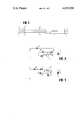
- FIG. 1is a plan view of a preferred form of voltage checker
- FIG. 2is a circuit diagram using a NPN transistor
- FIG. 3is another circuit diagram using a PNP transistor.
- the testerhas a housing 1 with a pencil clip 2 for carrying.
- an indicatorsuch as a light emitting diode 3 and at the lower end of the housing are flexible leads 4, 5 terminating in insulated hand grip sections 6, 7 and terminals 8, 9 for making contact to the points at which the existence of voltage is to be determined.
- Low voltage sound emittersmay be substituted for the light emitting diode to provide an audio indication.
- the existence of a voltage of 3 volts or to 250 or more voltsis indicated by current flowing through the light emitting diode. All of the current for the light emitting diode flows through diode or rectifier 10, resistor 11, and transistor 12.
- the diode 10changes a.c. to d.c., a necessary function.
- the testerwould burn up.
- the half wave rectifier 10is adequate. A full wave rectifier is not necessary.
- the half wave rectifierperforms the additional function of indicating polarity. With a.c. voltages, the terminals may be reversed without changing the indication. With d.c. voltages an indication can be obtained only when the terminal 8 is connected to a positive voltage.
- transistor 12When the terminals 8, 9 are connected across an unknown a.c. voltage, transistor 12 is biased on by the voltage applied through resistor 14 to base or control electrode 12b causing a flow of current through resistor 11, emitter 12e, collector 12c and light emitting diode 3.
- a voltage limiting meanssuch as zener diode 13, limits the sum of the voltage across resistor 11 (V) plus the emitter to base voltage (Veb) of the transistor to a value which cannot excede the rated voltage of the zener diode 13. The result is to limit the current through resistor 11 to a value less than the rated current of the light emitting diode, typically 15 milliamperes.
- the transistor 12sustains all voltages in excess of the voltage drop across the light emitting diode 3, and resistor 11, typically less than 3 volts. For this function the transistor acts as a variable resistor and the result is substantially constant current through the light emitting diode.
- Circuit values for the checker shown in FIG. 2are:
- Resistor 11330 Ohms 1/2 watt Advacom, Inc.
- Resistor 1427000 Ohms 1/2 watt Advacom, Inc.
- Zener diode 132.4 volt Solid State, Inc.
- FIG. 3is the same as FIG. 2, except for the change in polarity required by the PNP transistor. Corresponding parts are indicated by the same reference numerals primed.
Landscapes
- Physics & Mathematics (AREA)
- General Physics & Mathematics (AREA)
- Measurement Of Current Or Voltage (AREA)
Abstract
Description
Voltage checkers have been made with a lamp which lights to indicate the presence of a voltage. This type of checker can be made in pocket size and is convenient to use but has a limited range so that several checkers are required to cover a wide range of voltages.
This invention is intended to combine the functions of several narrow range testers into a single unit without increase in size or change in the method of use. The same circuit and the same indicator used for a voltage of 3 volts is also used without change for voltages of 250 volts and higher, a.c. or d.c.
In the drawing,
FIG. 1 is a plan view of a preferred form of voltage checker,
FIG. 2 is a circuit diagram using a NPN transistor, and
FIG. 3 is another circuit diagram using a PNP transistor.
The tester has a housing 1 with apencil clip 2 for carrying. At the upper end of the housing is an indicator such as alight emitting diode 3 and at the lower end of the housing are flexible leads 4, 5 terminating in insulatedhand grip sections 6, 7 andterminals 8, 9 for making contact to the points at which the existence of voltage is to be determined. Low voltage sound emitters may be substituted for the light emitting diode to provide an audio indication. The existence of a voltage of 3 volts or to 250 or more volts is indicated by current flowing through the light emitting diode. All of the current for the light emitting diode flows through diode orrectifier 10, resistor 11, andtransistor 12. Thediode 10 changes a.c. to d.c., a necessary function. If a.c. were not rectified the tester would burn up. Thehalf wave rectifier 10 is adequate. A full wave rectifier is not necessary. In the case of d.c. voltages, the half wave rectifier performs the additional function of indicating polarity. With a.c. voltages, the terminals may be reversed without changing the indication. With d.c. voltages an indication can be obtained only when theterminal 8 is connected to a positive voltage.
When theterminals 8, 9 are connected across an unknown a.c. voltage,transistor 12 is biased on by the voltage applied throughresistor 14 to base orcontrol electrode 12b causing a flow of current through resistor 11,emitter 12e,collector 12c andlight emitting diode 3. A voltage limiting means such aszener diode 13, limits the sum of the voltage across resistor 11 (V) plus the emitter to base voltage (Veb) of the transistor to a value which cannot excede the rated voltage of thezener diode 13. The result is to limit the current through resistor 11 to a value less than the rated current of the light emitting diode, typically 15 milliamperes. Because of the voltage limiting effect of thezener diode 13, thetransistor 12 sustains all voltages in excess of the voltage drop across thelight emitting diode 3, and resistor 11, typically less than 3 volts. For this function the transistor acts as a variable resistor and the result is substantially constant current through the light emitting diode.
Circuit values for the checker shown in FIG. 2 are:
Light emitting diode 3 (LSL-3L) Advacom, Inc.
Resistor 11 330 Ohms 1/2 watt Advacom, Inc.
Zenerdiode 13 2.4 volt Solid State, Inc.
FIG. 3 is the same as FIG. 2, except for the change in polarity required by the PNP transistor. Corresponding parts are indicated by the same reference numerals primed.
Other voltage limiting devices such as varistors may be substituted for thezeners 13, 13'.
Claims (7)
1. A passive total solid state pocket size voltage checker operative for testing voltages within a range of 3 to 250 volts comprising a housing, an indicating circuit within the housing comprising a rectifier, a resistor, a transistor, and an indicator in series with a pair of leads, said leads extending from the housing and having free ends provided with terminals for connection across an unknown voltage, said transistor having its emitter and collector in series with said resistor and said indicator, and means connected in said circuit for limiting the sum of the voltage across the resistor plus the emitter to base voltage of the transistor, and the transistor sustaining all voltage in excess of the voltage drop across the indicator and resistor.
2. The checker of claim 1 in which the indicator is a light emitting diode.
3. The checker of claim 1 in which the indicator is a sound emitter or like.
4. The checker of claim 1 in which the voltage limiting means is a zener.
5. The checker of claim 1 in which the voltage limiting means is a varistor.
6. The checker of claim 1 in which the voltage limiting means is a pn junction.
7. The checker of claim 1 in which the voltage limiting means is a semiconductor with a threshold voltage.
Priority Applications (1)
| Application Number | Priority Date | Filing Date | Title |
|---|---|---|---|
| US05/618,564US4025850A (en) | 1975-10-01 | 1975-10-01 | Passive, solid state wide range voltage checker |
Applications Claiming Priority (1)
| Application Number | Priority Date | Filing Date | Title |
|---|---|---|---|
| US05/618,564US4025850A (en) | 1975-10-01 | 1975-10-01 | Passive, solid state wide range voltage checker |
Publications (1)
| Publication Number | Publication Date |
|---|---|
| US4025850Atrue US4025850A (en) | 1977-05-24 |
Family
ID=24478223
Family Applications (1)
| Application Number | Title | Priority Date | Filing Date |
|---|---|---|---|
| US05/618,564Expired - LifetimeUS4025850A (en) | 1975-10-01 | 1975-10-01 | Passive, solid state wide range voltage checker |
Country Status (1)
| Country | Link |
|---|---|
| US (1) | US4025850A (en) |
Cited By (15)
| Publication number | Priority date | Publication date | Assignee | Title |
|---|---|---|---|---|
| US4184113A (en)* | 1977-11-07 | 1980-01-15 | Compu-Trol, Inc. | Method of counting electrical load current pulsations |
| US4247849A (en)* | 1979-03-19 | 1981-01-27 | Beta Products, Inc. | Constant current voltage sensing circuit |
| GB2125972A (en)* | 1982-08-25 | 1984-03-14 | Alan James Checkland Park | Domestic electrical tester |
| US4514724A (en)* | 1982-09-28 | 1985-04-30 | Paul W. Garbo | Electrical warning system for malfunctions in refrigeration |
| US4532466A (en)* | 1982-08-16 | 1985-07-30 | The Babcock & Wilcox Company | Constant current source for field contact input |
| US4605895A (en)* | 1984-03-09 | 1986-08-12 | Park Alan J C | Domestic electrical tester |
| WO1986006191A1 (en)* | 1985-04-11 | 1986-10-23 | Valentine Walter J | Electrical warning system for malfunctions in refrigeration |
| US4841240A (en)* | 1988-01-29 | 1989-06-20 | American Telephone And Telegraph Company, At&T Bell Laboratories | Method and apparatus for verifying the continuity between a circuit board and a test fixture |
| US5003250A (en)* | 1985-06-17 | 1991-03-26 | Hiroshi Hukuba | Voltage testing device for electric tooth-brush |
| DE4210051A1 (en)* | 1992-03-27 | 1992-11-26 | Daimler Benz Ag | METHOD AND DEVICE FOR HIGH VOLTAGE MEASUREMENT, IN PARTICULAR IN IGNITION SYSTEMS IN MOTOR VEHICLES |
| US5940280A (en)* | 1998-02-23 | 1999-08-17 | Nippon Electric Industry Co., Ltd. | Converter circuit of battery charger for electric vehicle |
| US6043703A (en)* | 1997-07-30 | 2000-03-28 | Allen-Bradley Company, Llc | Low power active input circuit |
| CN103383405A (en)* | 2013-07-10 | 2013-11-06 | 珠海许继芝电网自动化有限公司 | Passive signal voltage detection method |
| WO2014012900A1 (en) | 2012-07-20 | 2014-01-23 | Sma Solar Technology Ag | Dc reverse polarity detection |
| CN115586462A (en)* | 2022-09-01 | 2023-01-10 | 国能包神铁路集团有限责任公司 | A line test pen |
Citations (15)
| Publication number | Priority date | Publication date | Assignee | Title |
|---|---|---|---|---|
| US2575821A (en)* | 1948-10-21 | 1951-11-20 | William C Linton | Pocket-size circuit tester |
| US2921264A (en)* | 1953-01-27 | 1960-01-12 | Sundt Engineering Company | Protection system for meters or the like |
| US2956229A (en)* | 1959-04-27 | 1960-10-11 | James L Henel | Voltage and polarity tester |
| US2994039A (en)* | 1960-01-19 | 1961-07-25 | Marine Electric Corp | Self-protecting meter |
| US3157870A (en)* | 1961-05-09 | 1964-11-17 | Marquette Corp | Method and means of voltage testing |
| US3281816A (en)* | 1964-01-20 | 1966-10-25 | Eugene B Raymond | Polarity protected booster cable |
| US3355729A (en)* | 1963-10-22 | 1967-11-28 | English Electric Co Ltd | Potential difference detecting arrangements |
| DE1931994A1 (en)* | 1968-06-27 | 1970-01-08 | Falconi & Co S P A G | Pocket device for checking the electrical condition of circuits, semiconductors and electrical switching elements or the like. |
| US3531790A (en)* | 1966-12-16 | 1970-09-29 | Chance Co Ab | Energized line indicator |
| US3534354A (en)* | 1966-07-01 | 1970-10-13 | Gen Electric | Discharge indicator for rechargeable batteries |
| US3694749A (en)* | 1970-11-25 | 1972-09-26 | Joseph Woroble | Ac line voltage drop indicator plug |
| US3771049A (en)* | 1971-01-05 | 1973-11-06 | Dossert Mfg Corp | Fault indicator and locator for buried cables and zero sequence current sensing device |
| US3784903A (en)* | 1970-11-10 | 1974-01-08 | Rca Corp | Leakage detector for determining possible shock hazards to humans |
| US3878459A (en)* | 1972-05-05 | 1975-04-15 | Harry A Hanna | Electrostatic field detection method for determining whether apparatus is properly grounded |
| US3934195A (en)* | 1974-02-04 | 1976-01-20 | Surf Air Conditioning, Inc. | Portable electric capacitor tester using an LED indicator |
- 1975
- 1975-10-01USUS05/618,564patent/US4025850A/ennot_activeExpired - Lifetime
Patent Citations (15)
| Publication number | Priority date | Publication date | Assignee | Title |
|---|---|---|---|---|
| US2575821A (en)* | 1948-10-21 | 1951-11-20 | William C Linton | Pocket-size circuit tester |
| US2921264A (en)* | 1953-01-27 | 1960-01-12 | Sundt Engineering Company | Protection system for meters or the like |
| US2956229A (en)* | 1959-04-27 | 1960-10-11 | James L Henel | Voltage and polarity tester |
| US2994039A (en)* | 1960-01-19 | 1961-07-25 | Marine Electric Corp | Self-protecting meter |
| US3157870A (en)* | 1961-05-09 | 1964-11-17 | Marquette Corp | Method and means of voltage testing |
| US3355729A (en)* | 1963-10-22 | 1967-11-28 | English Electric Co Ltd | Potential difference detecting arrangements |
| US3281816A (en)* | 1964-01-20 | 1966-10-25 | Eugene B Raymond | Polarity protected booster cable |
| US3534354A (en)* | 1966-07-01 | 1970-10-13 | Gen Electric | Discharge indicator for rechargeable batteries |
| US3531790A (en)* | 1966-12-16 | 1970-09-29 | Chance Co Ab | Energized line indicator |
| DE1931994A1 (en)* | 1968-06-27 | 1970-01-08 | Falconi & Co S P A G | Pocket device for checking the electrical condition of circuits, semiconductors and electrical switching elements or the like. |
| US3784903A (en)* | 1970-11-10 | 1974-01-08 | Rca Corp | Leakage detector for determining possible shock hazards to humans |
| US3694749A (en)* | 1970-11-25 | 1972-09-26 | Joseph Woroble | Ac line voltage drop indicator plug |
| US3771049A (en)* | 1971-01-05 | 1973-11-06 | Dossert Mfg Corp | Fault indicator and locator for buried cables and zero sequence current sensing device |
| US3878459A (en)* | 1972-05-05 | 1975-04-15 | Harry A Hanna | Electrostatic field detection method for determining whether apparatus is properly grounded |
| US3934195A (en)* | 1974-02-04 | 1976-01-20 | Surf Air Conditioning, Inc. | Portable electric capacitor tester using an LED indicator |
Cited By (17)
| Publication number | Priority date | Publication date | Assignee | Title |
|---|---|---|---|---|
| US4184113A (en)* | 1977-11-07 | 1980-01-15 | Compu-Trol, Inc. | Method of counting electrical load current pulsations |
| US4247849A (en)* | 1979-03-19 | 1981-01-27 | Beta Products, Inc. | Constant current voltage sensing circuit |
| US4532466A (en)* | 1982-08-16 | 1985-07-30 | The Babcock & Wilcox Company | Constant current source for field contact input |
| GB2125972A (en)* | 1982-08-25 | 1984-03-14 | Alan James Checkland Park | Domestic electrical tester |
| US4514724A (en)* | 1982-09-28 | 1985-04-30 | Paul W. Garbo | Electrical warning system for malfunctions in refrigeration |
| US4605895A (en)* | 1984-03-09 | 1986-08-12 | Park Alan J C | Domestic electrical tester |
| WO1986006191A1 (en)* | 1985-04-11 | 1986-10-23 | Valentine Walter J | Electrical warning system for malfunctions in refrigeration |
| US5003250A (en)* | 1985-06-17 | 1991-03-26 | Hiroshi Hukuba | Voltage testing device for electric tooth-brush |
| US4841240A (en)* | 1988-01-29 | 1989-06-20 | American Telephone And Telegraph Company, At&T Bell Laboratories | Method and apparatus for verifying the continuity between a circuit board and a test fixture |
| DE4210051A1 (en)* | 1992-03-27 | 1992-11-26 | Daimler Benz Ag | METHOD AND DEVICE FOR HIGH VOLTAGE MEASUREMENT, IN PARTICULAR IN IGNITION SYSTEMS IN MOTOR VEHICLES |
| US6043703A (en)* | 1997-07-30 | 2000-03-28 | Allen-Bradley Company, Llc | Low power active input circuit |
| US5940280A (en)* | 1998-02-23 | 1999-08-17 | Nippon Electric Industry Co., Ltd. | Converter circuit of battery charger for electric vehicle |
| WO2014012900A1 (en) | 2012-07-20 | 2014-01-23 | Sma Solar Technology Ag | Dc reverse polarity detection |
| DE102012106612A1 (en)* | 2012-07-20 | 2014-05-15 | Sma Solar Technology Ag | DC mispolarization |
| US9632116B2 (en) | 2012-07-20 | 2017-04-25 | Sma Solar Technology Ag | DC reverse polarity detection |
| CN103383405A (en)* | 2013-07-10 | 2013-11-06 | 珠海许继芝电网自动化有限公司 | Passive signal voltage detection method |
| CN115586462A (en)* | 2022-09-01 | 2023-01-10 | 国能包神铁路集团有限责任公司 | A line test pen |
Similar Documents
| Publication | Publication Date | Title |
|---|---|---|
| US4025850A (en) | Passive, solid state wide range voltage checker | |
| US4301407A (en) | Hand held testing device for indicating an electric test voltage | |
| US4006396A (en) | Universal battery charging apparatus | |
| GB753014A (en) | Semiconductor electric signal translating devices | |
| KR890003132A (en) | Temperature Stable RF Detector | |
| US4420786A (en) | Polarity guard circuit | |
| US3259841A (en) | Negative-feedback transistorized electrical continuity tester | |
| GB1565218A (en) | Electrical continuity and voltagetesting device | |
| KR870008240A (en) | Reference voltage circuit | |
| US3283244A (en) | Electrical resistance tester | |
| US4031417A (en) | Apparatus for coupling a digital data generator to a digital data readout device with electrical isolation therebetween | |
| KR900011096A (en) | Telephone protection circuit | |
| KR840002351Y1 (en) | Circuit connection test circuit | |
| KR900003374Y1 (en) | Checking circuit of thermometer using thermistor | |
| SU1705752A1 (en) | Power tester | |
| RU217237U1 (en) | UNIVERSAL PROBE ELECTRICIAN | |
| SU1688178A1 (en) | Device for checking electrical chains and voltages | |
| SU1167507A1 (en) | Device for protection of electrical instruments | |
| RU2076329C1 (en) | Indicator of polarity, current type and circuit resistance | |
| SU602926A2 (en) | Ac limiting stabilizer | |
| KR950006752Y1 (en) | The battery voltage detecting circuit of mobile phone | |
| GB910045A (en) | Improvements in shot exploders | |
| SU1176316A1 (en) | Electric power supply device | |
| SU868879A1 (en) | Device for indicating safety-cutout state | |
| SU1515282A1 (en) | Transistor filter |