US4020332A - Interpolation-decimation circuit for increasing or decreasing digital sampling frequency - Google Patents
Interpolation-decimation circuit for increasing or decreasing digital sampling frequencyDownload PDFInfo
- Publication number
- US4020332A US4020332AUS05/616,283US61628375AUS4020332AUS 4020332 AUS4020332 AUS 4020332AUS 61628375 AUS61628375 AUS 61628375AUS 4020332 AUS4020332 AUS 4020332A
- Authority
- US
- United States
- Prior art keywords
- input
- sample
- samples
- circuit
- coefficients
- Prior art date
- Legal status (The legal status is an assumption and is not a legal conclusion. Google has not performed a legal analysis and makes no representation as to the accuracy of the status listed.)
- Expired - Lifetime
Links
- 238000005070samplingMethods0.000titleclaimsabstractdescription45
- 230000003247decreasing effectEffects0.000titleabstractdescription3
- 238000012163sequencing techniqueMethods0.000claimsdescription12
- 238000006243chemical reactionMethods0.000claimsdescription11
- 230000004044responseEffects0.000claimsdescription9
- 230000006870functionEffects0.000claimsdescription2
- 238000009825accumulationMethods0.000claims1
- 230000000694effectsEffects0.000abstract1
- 239000000523sampleSubstances0.000description39
- 238000004364calculation methodMethods0.000description26
- 230000007423decreaseEffects0.000description5
- 238000012545processingMethods0.000description5
- 238000000034methodMethods0.000description4
- 230000003213activating effectEffects0.000description2
- 238000007792additionMethods0.000description2
- 230000005540biological transmissionEffects0.000description2
- 238000010586diagramMethods0.000description2
- 238000012546transferMethods0.000description2
- 240000007320Pinus strobusSpecies0.000description1
- 108010076504Protein Sorting SignalsProteins0.000description1
- 238000013459approachMethods0.000description1
- 238000013461designMethods0.000description1
- 238000013213extrapolationMethods0.000description1
- 238000001914filtrationMethods0.000description1
- 230000008929regenerationEffects0.000description1
- 238000011069regeneration methodMethods0.000description1
Images


Classifications
- H—ELECTRICITY
- H03—ELECTRONIC CIRCUITRY
- H03H—IMPEDANCE NETWORKS, e.g. RESONANT CIRCUITS; RESONATORS
- H03H17/00—Networks using digital techniques
- H03H17/02—Frequency selective networks
- H03H17/06—Non-recursive filters
- H03H17/0621—Non-recursive filters with input-sampling frequency and output-delivery frequency which differ, e.g. extrapolation; Anti-aliasing
- H03H17/0635—Non-recursive filters with input-sampling frequency and output-delivery frequency which differ, e.g. extrapolation; Anti-aliasing characterized by the ratio between the input-sampling and output-delivery frequencies
- H03H17/0685—Non-recursive filters with input-sampling frequency and output-delivery frequency which differ, e.g. extrapolation; Anti-aliasing characterized by the ratio between the input-sampling and output-delivery frequencies the ratio being rational
Definitions
- Apparatus for increasing or decreasing a digital system sampling rateis required, for example, in the conversion of a digital signal code format, e.g., conversion from delta modulation at one sampling rate to pulse code modulation at a second sampling rate.
- Another useis the transmission of speech in an analysissynthesis system, such as a vocoder, wherein sampling rate reduction is required for efficient transmission and sampling rate increase is required for regeneration of the speech at the receiving terminal.
- decimation and interpolation circuitswhich do not require either complex circuitry operating at several sampling frequencies or complex logic circuitry to implement the required signal multiplications.
- the filter coefficientsare functions of the desired decimation and interpolation factors. More specifically, the interpolation-decimation circuit of this invention employs L sets of filter coefficients, where L is the desired interpolation factor, with a particular set of coefficients being employed to determine the value of each point of the output signal. Each set of coefficients is stored in a memory unit, with coefficients within each set arranged in a specific predetermined order to allow sequential addressing of both the input signal data and the stored coefficients.
- Embodiments as a single-stage interpolator-decimator and as multiple stage decimators and interpolators to implement a narrow-band FIR filterare included.
- FIG. 1depicts, in block diagram form, a general purpose interpolator-decimator circuit which is helpful in understanding this invention
- FIG. 2illustrates an embodiment of a single-stage interpolator-decimator circuit in accordance with this invention
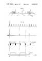
- FIG. 3depicts the timing diagram of the single-stage interpolator-decimator of FIG. 2.
- FIG. 4depicts multistage embodiments of this invention employed as a narrow-band FIR filter.
- a digital input signal having a sampling frequency f ris applied to input terminal 11.
- Sampling rate increase unit 12increases the sampling frequency to Lf r by inserting L-1 zero-valued samples between the samples of input signal x(n).
- This signal, denoted w(n) in FIG. 1is low-pass filtered by filter 13 to produce the signal denoted as v(n).
- Low-pass filter 13is preferably an FIR filter realized by a standard direct form implementation, since savings in computation can thereby be realized.
- filter 13is an FIR filter
- Sampling rate decrease circuit 14decreases the sampling rate by effectively selecting every Mth sample of the interpolated signal v(n). Accordingly, the signal coupled to output terminal 16 exhibits the sampling frequency (L/M)f r , where L and M may be selected to provide decimation or interpolation by any rational number.
- Equation (1)it can be seen that the computation of an output point depends solely on past and present values of w(n) and not upon past values of any internal filter variables. Thus, the filter computations need only be performed for every Mth output signal. Furthermore, since w(n) is non-zero only for every Lth input point, only a single multiplication and addition need be performed for every Lth input point. Thus, in the interpolator-decimator of FIG. 1, the effective number of multiplications and additions perfomed by the circuit is N/(LM) per output sample instead of N, as would be predicted by a cursory examination of Equation (1).
- interpolation-decimation circuit of FIG. 1could be realized by utilizing state-of-the art interpolator-decimator and filter circuits, such an implementation is generally very complicated, since it involves signals at several different sampling rates and also involves keeping track of the particular multiplication which must be performed.
- the sequence or set g 1 (n), of Q coefficients g 1 (n)h(M ⁇ L), h(L+M ⁇ L), . . .
- FIG. 2depicts an embodiment of our invention employing the above principles to realize a general purpose interpolator-decimator.
- Q samples of the input signalare stored in shift register 27 and the h(n) coefficients are stored in memory 41 (e.g., a conventional read-only (ROM) memory) in the scrambled order described above.
- memory 41e.g., a conventional read-only (ROM) memory
- a particular output sample y(n)is calculated by sequentially shifting an input sample from shift register 27 and the corresponding coefficient from memory 41 to the input terminals of multiplier 29.
- the product of the input sample and the coefficientis coupled to accumulator 31, which may be a conventional accumulator circuit which normally includes an adder and a register wherein the quantity contained in the register is added to the incoming signal and the resulting sum is stored in the register.
- Multiplier 29can be any conventional multiplier circuit capable of handling the digital format employed in any particular embodiment.
- countdown circuit 35which effectively counts down from the system master clock frequency, Lf r , (applied to terminal 34) to supply a signal of frequency L/M f r , i.e., countdown circuit 35 counts down M samples from the master clock.
- Lf rsystem master clock frequency
- countdown circuit 35counts down M samples from the master clock.
- the output pulse of countdown circuit 35initiates the calculation sequence by transferring the data stored in buffer memory 22 into shift register 27. This transfer is effected by Clock 25 and counter 30 which operate in conjunction with counter 23 and address circuit 24.
- the output pulse of countdown circuit 35starts clock 25 which operates at a frequency high enough to generate at least as many clock pulses as the maximum number of input samples which must be loaded into shift register 27 before Q-clock 37 begins to operate.
- Each clock pulse of clock 25increments address circuit 24 and strobes buffer memory 22 to transfer the data samples in buffer memory 22 to shift register 27. These data samples are transferred to the shift register in the order in which they arrived at input terminal 21.
- the clock pulses generated by clock 25are counted by counter 30. When the count reaches the count stored in counter 23, the last updating sample is transferred to shift register 27 and counter 30 stops clock 25 and resets counter 23 back to zero. Additionally, the output pulse of countdown circuit 35 switches the state of bistable multivibrator 36 which, in turn, starts Q-clock 37 running.
- Q-clock 37is a conventional clock circuit which has a frequency high enough to generate Q pulses during the period M/(Lf r ).
- Multivibrator 36is a conventional multivibrator which operates with a sufficient delay to allow completion of the above-described loading sequence.
- address pointer 39was automatically indexed to the storage location of the proper coefficient block at the conclusion of the previous calculation sequence. For example, if the previous calculation sequence determined output sample y(0), address pointer 39 would be initially indexed to the last coefficient stored in block 43 of memory unit 41 to begin the calculation of output sample y(1). In this case, shift register 27 would contain the input samples
- shift register 27would contain the proper input samples in an ordered sequence due to the previously discussed operation of memory 22, counters 23 and 30, address circuit 24, and clock 25.
- clock pulses from Q-clock 37sequentially shift input sample x([nM/L] - k) and coefficient h(kL + (nM) ⁇ L) to multiplier 29.
- the first clock pulse from Q-clock 37shifts x([M/L]-(Q-1)) to one input terminal of multiplier 29, while the coefficient h((Q-1)L + M ⁇ L) is coupled to the second input terminal of multiplier 29.
- each input sampleis recirculated to the input terminal of shift register 27 as it is shifted to the input of multiplier 29.
- address pointer 39is advanced to the next storage location within memory 41 to provide the proper coefficient to the second input terminal of multiplier 29.
- Q-counter 38which is a conventional counting circuit, counts the number of clock pulses generated by Q-clock 37. When Q-clock pulses have been generated, the calculation of the output sample will be complete and the value of the output sample will be stored in accumulator 31. Upon reaching the count of Q, Q-counter 38 causes bistable multivibrator 36 to be reset, shutting off Q-clock 37, while simultaneously activating selector 26 to connect the input terminal of shift register 27 to the output terminal of buffer memory 22.
- address pointer 39would be indexed to the last coefficient in the g 2 (n) block of coefficients within memory 41, i.e., h((Q-1)L + (2M) ⁇ L) and shift register 27 would hold input samples x([M/L]), x([M/L] - 1), . . . ,x([M/L] - (Q-1)).
- counter 23 and address unit 24have been in operation to count a number of arriving input samples and store each arriving sample in buffer memory 22.
- the frequency of Q-clock 37is high enough to ensure that each calculation is complete prior to an output pulse from countdown circuit 35, that is, the Q calculations necessary to determine a particular output sample are completed in a period of time less than M/(Lf r ).
- the input samples necessary to compute the next output samplemay or may not have arrived at input terminal 21 when the calculation of a particular output sample is complete. In any case, the samples will arrive prior to an output pulse from countdown circuit 35.
- countdown circuit 35When countdown circuit 35 reaches the count M it stops counter 23 and address circuit 24 which, as previously described, in conjunction with clock 25 and counter 30, sequentially shift the input samples stored in buffer memory 22 into shift register 27. Simultaneously, countdown circuit 35 sets bistable multivibrator 36 which starts Q-clock 37, thus beginning the calculation of the next output sample.
- the number of samples to be transferred from buffer memory 22 to shift register 27varies not only with the particular interpolator-decimator ratio L/M, but may also vary during the calculation of particular output samples for a given ratio L/M.
- L/Mis greater than one, i.e., the circuit is an interpolator, either zero or one update input sample is required for the calculation of any output point y(n).
- the storage capacity of buffer memory 22is determined by the ratio L/M of a particular embodiment.
- f ris the sampling frequency of the digital system, i.e., an input sample arrives at input terminal 21, with each pulse in the signal f r .
- the output of countdown logic 35labeled f rLM in FIG. 3, is derived from the digital system master clock signal, Lf r , by counting down by the factor M.
- the Q-clock signal f Qis initiated by each output pulse f rLM and Q-counter output f Qc turns Q-clock 37 off after Q-clock pulses have been generated.
- FIG. 3corresponds to the time interval in which two output samples are calculated.
- t 0 to t 1four input samples arrive at input terminal 21 and are stored in buffer memory 22.
- these four sampleswill be shifted into shift register 27 to update the system for the calculation of the next output sample.
- the systemis calculating this output, i.e., during the period of time from t 1 until Q-counter 38 reaches the count Q at t 1 ', three input samples arrive at input terminal 21 and are stored in buffer memory 22.
- buffer memory 22always holds the proper number of updating input samples at the beginning of each new calculation sequence.
- FIG. 4depicts an illustrative example of a multistage embodiment of our invention with n-stages in which L/M ⁇ 1 (n decimators) are cascaded with n stages in which L/M>1 (n interpolators) to realize a narrow-band FIR filter.
- the sampling rate of the output signal at terminal 32will be identical to the sampling rate of the input signal at terminal 21. Accordingly, in most instances ##EQU3##
- the master clock frequency of each decimator stagemay, of course, be determined from a single master clock frequency, L i f ri , by counting down from the clock frequency applied to stage (i - 1) by the factor M i .
- the master clock frequencies of each of the n interpolation stagesmay be determined from the clock frequency of the preceding interpolator stage by counting up by the appropriate factor M i .
- each decimator-interpolator stageincludes buffer memory 22-i, multiplier 29-i, accumulator 31-i, and coefficient memory 41-i. Since each of the n stages of decimation and each of the n stages of interpolation also include circuit sequencing means such as depicted in the embodiment of the single-stage interpolator-decimator of FIG. 2, the circuits effectively operate independently of one another. That is, the (i+1)th stage simultaneously processes the previous data output of the ith stage, while the ith stage processes signal samples of the next processing interval. Such a configuration is commonly denoted as a "pipeline" design.
Landscapes
- Physics & Mathematics (AREA)
- Engineering & Computer Science (AREA)
- Computer Hardware Design (AREA)
- Mathematical Physics (AREA)
- Transmission Systems Not Characterized By The Medium Used For Transmission (AREA)
- Compression, Expansion, Code Conversion, And Decoders (AREA)
- Complex Calculations (AREA)
Abstract
Description
This invention is closely related to the copending application for patent, Crochiere-Rabiner-Shively Ser. No,. 610,540, filed Sept. 5, 1975.
With the increasing number of uses of digital technology in signal processing, the need for efficiently translating between various sampling rates has become apparent. Apparatus for increasing or decreasing a digital system sampling rate is required, for example, in the conversion of a digital signal code format, e.g., conversion from delta modulation at one sampling rate to pulse code modulation at a second sampling rate. Another use is the transmission of speech in an analysissynthesis system, such as a vocoder, wherein sampling rate reduction is required for efficient transmission and sampling rate increase is required for regeneration of the speech at the receiving terminal.
Yet another use, disclosed by Bellanger, Daguet and Lepagnol in "Interpolation, Extrapolation and Reduction of Computational Speed in Digital Filters," IEEE Transactions on Acoustics, Speech and Signal Processing, Vol. ASSP-22, No. 4, pages 231-235, August 1974, is the efficient realization of finite impulse response (FIR) digital filters by multistage decimators and interpolators. In the Bellanger et al filter, the sampling rate is first reduced, the signal is filtered, and then the sampling rate is increased to that of the original signal. The sampling rate decrease was realized by Bellanger et al with multistage decimation circuits which were half-band filters, with each filter reducing the sampling rate by a factor of two. In accordance with the Bellanger et al disclosure, the frequency was increased to the original sampling frequency by a reverse process which again employed interpolation by a factor of two at each stage.
Schafer and Rabiner, in "A Digital Signal Processing Approach to Interpolation," Proceedings of the IEEE, Vol. 61, No. 6, pages 692-702, June, 1973, have shown that decimation and interpolation can be efficiently implemented using FIR filters. Further, in this article, Schafer and Rabiner demonstrate that the sampling rate conversion between any rational ratio of sampling frequencies can be efficiently implemented by a two-stage process consisting of an integer sampling rate increase, followed by an integer sampling rate decrease.
Although the prior art has demonstrated that single stage or multistage interpolation and decimation result in computational efficiency, the prior art has not provided an interpolation or decimation circuit which can be realized by relatively simple circuit structure. In fact, implementations proposed by the prior art, e.g., the FIR filter of Bellanger et al, are structurally complex since such systems involve signals at several different sampling rates and also require circuit means which effectively keep track of when particular multiplications must be performed. Moreover, the prior art circuits have generally been designed for a specific application and have not been suited for widespread usage.
Accordingly, it is an object of this invention to realize decimation and interpolation circuits which can be used in a wide variety of digital processing applications.
Further, it is an object of this invention to realize decimation and interpolation circuits which do not require either complex circuitry operating at several sampling frequencies or complex logic circuitry to implement the required signal multiplications.
These and other objects are achieved in accordance with this invention by a circuit similar in structure to the direct form realization of a finite impulse response (FIR) filter circuit. In accordance with this invention, the filter coefficients are functions of the desired decimation and interpolation factors. More specifically, the interpolation-decimation circuit of this invention employs L sets of filter coefficients, where L is the desired interpolation factor, with a particular set of coefficients being employed to determine the value of each point of the output signal. Each set of coefficients is stored in a memory unit, with coefficients within each set arranged in a specific predetermined order to allow sequential addressing of both the input signal data and the stored coefficients. Embodiments as a single-stage interpolator-decimator and as multiple stage decimators and interpolators to implement a narrow-band FIR filter are included.
FIG. 1 depicts, in block diagram form, a general purpose interpolator-decimator circuit which is helpful in understanding this invention;
FIG. 2 illustrates an embodiment of a single-stage interpolator-decimator circuit in accordance with this invention;
FIG. 3 depicts the timing diagram of the single-stage interpolator-decimator of FIG. 2; and
FIG. 4 depicts multistage embodiments of this invention employed as a narrow-band FIR filter.
FIG. 1 depicts a circuit for changing the sampling rate of an applied signal by the factor L/M. It will be recognized by those skilled in the art that this structure is effectively an interpolator circuit cascaded with a decimator circuit in which the interpolator low-pass filter and decimator low-pass filter have been combined in single low-pass filter 13. Since the circuit of FIG. 1 first increases the sampling frequency by an integer factor L and subsequently decreases the sampling frequency by an integer factor M, it can be observed that the sampling rate conversion of the circuit is L/M. Thus, the circuit of FIG. 1 is a general interpolation-decimation circuit in which the interpolation or decimation factor is determined by L and M. Accordingly, if L=1, the circuit becomes an integer decimator, and if M=1, the circuit becomes a typical integer interpolator.
In the operation of the circuit of FIG. 1, a digital input signal having a sampling frequency fr is applied to input terminal 11. Sampling rate increaseunit 12 increases the sampling frequency to Lfr by inserting L-1 zero-valued samples between the samples of input signal x(n). This signal, denoted w(n) in FIG. 1, is low-pass filtered byfilter 13 to produce the signal denoted as v(n). Low-pass filter 13 is preferably an FIR filter realized by a standard direct form implementation, since savings in computation can thereby be realized. Whenfilter 13 is an FIR filter, the signal v(n) is related to the signal w(n) by ##EQU1## where h(m), m=0, 1 . . . , N-1 are the filter coefficients and N is the duration of the unit sample response offilter 13.
Sampling rate decreasecircuit 14 decreases the sampling rate by effectively selecting every Mth sample of the interpolated signal v(n). Accordingly, the signal coupled tooutput terminal 16 exhibits the sampling frequency (L/M)fr, where L and M may be selected to provide decimation or interpolation by any rational number.
From Equation (1), it can be seen that the computation of an output point depends solely on past and present values of w(n) and not upon past values of any internal filter variables. Thus, the filter computations need only be performed for every Mth output signal. Furthermore, since w(n) is non-zero only for every Lth input point, only a single multiplication and addition need be performed for every Lth input point. Thus, in the interpolator-decimator of FIG. 1, the effective number of multiplications and additions perfomed by the circuit is N/(LM) per output sample instead of N, as would be predicted by a cursory examination of Equation (1).
Although the interpolation-decimation circuit of FIG. 1 could be realized by utilizing state-of-the art interpolator-decimator and filter circuits, such an implementation is generally very complicated, since it involves signals at several different sampling rates and also involves keeping track of the particular multiplication which must be performed.
Utilizing the concepts of the circuit of FIG. 1, we have discovered that a general interpolator-decimator circuit can be realized by relatively simple circuit structure which is similar to the direct form implementation of an FIR filter. If the unit sample response duration of low-pass filter 13 is N samples, L-1 out of every L samples of w(n) are zero-valued and thus the computation is proportional to N/L, since the unit sample response spans approximately N/L non-zero samples. If N is chosen to be N=QL where Q is a predetermined integer, then the unit sample response will span exactly Q non-zero samples of w(n) for each filter cycle. It can be seen that this condition can be easily satisfied since h(n) can be appended with a small number of zero-valued coefficients until N is equal to QL. Defining N in this manner, we have determined that each output point y(n) is of the form ##EQU2## where (nM) ⊕ L denotes nM modulo L, [nM/L] denotes nM/L rounded up to the next largest interger, and the sequence h(n), n=0, 1, . . . , N-1 contains the coefficients of the direct form FIR filter, (or, equivalently, the samples of its impulse response).
It can be noted in Equation (2) that to compute each output point y(n), x(n) is sequentially addressed for Q of its values and that [(n+1)M/L] - [nM/L] new input samples are required for the calculation of the next output point, y(n+1). Examining the expression for h(n) in Equation (1), it can be further noted that during the calculation of any output sample y(n), h(n) must be addressed to arguments, (kL+(nM) ⊕ L), where L), where K=0, 1, . . . Q-1 Thus, h(n) can be addressed sequentially only if the coefficients of h(n) are stored in an appropriate scrambled order. That is, to determine y(0) the sequence or set g0 (n) of Q coefficents g0 (n) = h(0), h(L), . . . , h((Q-1)L) is required. To determine y(1), the sequence or set g1 (n), of Q coefficients g1 (n) = h(M ⊕ L), h(L+M ⊕L), . . . h((Q-1)L+M ⊕ L) is required, whereas to compute y(L-1) the sequence gL-1 (n), of Q coefficients gL-1 (n) = h(((L-1)M) ⊕ L), h(L+((L-1)M) ⊕ L), . . . , h((Q-1)L + ((L-1)M) ⊕ L) is needed. Finally, to compute y(L), the sequence g0 (n) is again required and the cycle repeats.
FIG. 2 depicts an embodiment of our invention employing the above principles to realize a general purpose interpolator-decimator. In FIG. 2, Q samples of the input signal are stored inshift register 27 and the h(n) coefficients are stored in memory 41 (e.g., a conventional read-only (ROM) memory) in the scrambled order described above.
A particular output sample y(n) is calculated by sequentially shifting an input sample fromshift register 27 and the corresponding coefficient frommemory 41 to the input terminals ofmultiplier 29. The product of the input sample and the coefficient is coupled toaccumulator 31, which may be a conventional accumulator circuit which normally includes an adder and a register wherein the quantity contained in the register is added to the incoming signal and the resulting sum is stored in the register. Multiplier 29 can be any conventional multiplier circuit capable of handling the digital format employed in any particular embodiment.
The operation of the circuit of FIG. 2 can be best understood by assuming that a particular output sample y(n-1) has just been determined and the circuit is starting the sequence to determine the output sample y(n). At the beginning of such a sequence, signal samples which arrived during the calculation of y(n-1) are contained inbuffer memory 22, which may be any conventional memory circuit of suitable capacity. As each of the signals stored inmemory 22 arrived atinput terminal 21,counter 23 was incremented one count andaddress circuit 24 directed each input sample into a separate addressable location withinbuffer memory 22. Thus, at the beginning of any given sequence,counter 23 contains the number of input samples which are contained inbuffer memory 22 and must be loaded intoshift register 27 for the new calculation sequence. In addition, at the end of the previous sequence, Q-counter 38 ofsequencer 33 reached the count Q, activatingselector circuit 26 to connect the input ofshift register 27 to buffermemory 22.
The calculation sequence is initiated bycountdown circuit 35 which effectively counts down from the system master clock frequency, Lfr, (applied to terminal 34) to supply a signal of frequency L/M fr, i.e.,countdown circuit 35 counts down M samples from the master clock. It will be understood by those skilled in the art that a variety of such countdown circuits are available, e.g., logic gates may be connected directly to the system master clock to generate a single pulse each time the master clock reaches a predetermined count. The output pulse ofcountdown circuit 35 initiates the calculation sequence by transferring the data stored inbuffer memory 22 intoshift register 27. This transfer is effected byClock 25 and counter 30 which operate in conjunction withcounter 23 andaddress circuit 24. The output pulse ofcountdown circuit 35starts clock 25 which operates at a frequency high enough to generate at least as many clock pulses as the maximum number of input samples which must be loaded intoshift register 27 before Q-clock 37 begins to operate. Each clock pulse ofclock 25 increments addresscircuit 24 andstrobes buffer memory 22 to transfer the data samples inbuffer memory 22 to shiftregister 27. These data samples are transferred to the shift register in the order in which they arrived atinput terminal 21. The clock pulses generated byclock 25 are counted bycounter 30. When the count reaches the count stored incounter 23, the last updating sample is transferred to shiftregister 27 and counter 30 stopsclock 25 and resets counter 23 back to zero. Additionally, the output pulse ofcountdown circuit 35 switches the state ofbistable multivibrator 36 which, in turn, starts Q-clock 37 running. Q-clock 37 is a conventional clock circuit which has a frequency high enough to generate Q pulses during the period M/(Lfr).Multivibrator 36 is a conventional multivibrator which operates with a sufficient delay to allow completion of the above-described loading sequence.
The clock pulses from Q-clock 37 are coupled to shiftregister 27 andaddress pointer 39. As will become apparent from the following discussion,address pointer 39 was automatically indexed to the storage location of the proper coefficient block at the conclusion of the previous calculation sequence. For example, if the previous calculation sequence determined output sample y(0),address pointer 39 would be initially indexed to the last coefficient stored inblock 43 ofmemory unit 41 to begin the calculation of output sample y(1). In this case,shift register 27 would contain the input samples
x([M/L]), x([M/L]-1), . . . ,x([M/L] - (Q-1)).
it can be noted that regardless of which output sample was being calculated,shift register 27 would contain the proper input samples in an ordered sequence due to the previously discussed operation ofmemory 22, counters 23 and 30,address circuit 24, andclock 25.
During the calculation of each output sample y(n), clock pulses from Q-clock 37 sequentially shift input sample x([nM/L] - k) and coefficient h(kL + (nM) ⊕ L) tomultiplier 29. Thus, for example, in the calculation of output sample y(1), the first clock pulse from Q-clock 37 shifts x([M/L]-(Q-1)) to one input terminal ofmultiplier 29, while the coefficient h((Q-1)L + M ⊕ L) is coupled to the second input terminal ofmultiplier 29. Sinceselector 26 was activated bymultivibrator 36 at the same time Q-clock 37 was energized, each input sample is recirculated to the input terminal ofshift register 27 as it is shifted to the input ofmultiplier 29. With each clock pulse from Q-clock 37, the next input sample is shifted to one input terminal ofmultiplier 29 andaddress pointer 39 is advanced to the next storage location withinmemory 41 to provide the proper coefficient to the second input terminal ofmultiplier 29.
Q-counter 38, which is a conventional counting circuit, counts the number of clock pulses generated by Q-clock 37. When Q-clock pulses have been generated, the calculation of the output sample will be complete and the value of the output sample will be stored inaccumulator 31. Upon reaching the count of Q, Q-counter 38 causesbistable multivibrator 36 to be reset, shutting off Q-clock 37, while simultaneously activatingselector 26 to connect the input terminal ofshift register 27 to the output terminal ofbuffer memory 22. For example, in the calculation of the output sample y(1), after the (Q-1)th clockpulse address pointer 39 will be indexed to the coefficient h(M ⊕ L) incoefficient block 43 ofmemory 41 and the input sample x([M/L]) will be in the final register ofshift register 27. The Qth clock pulse will then couple this input signal and coefficient tomultiplier 29 and the product will be added to the sum of the previous products byaccumulator 31. At this point, calculation of a single output sample is complete and the value of the sample is stored inaccumulator 31. It should be noted that the Qth clock pulse ofclock 37 sets addresspointer 39 to the last coefficient of the next output sequence g2 (n) and recirculates the last input sample of the interval calculated withinshaft register 27. For example, in the previously referred to case of the determination of y(1),address pointer 39 would be indexed to the last coefficient in the g2 (n) block of coefficients withinmemory 41, i.e., h((Q-1)L + (2M) ⊕ L) andshift register 27 would hold input samples x([M/L]), x([M/L] - 1), . . . ,x([M/L] - (Q-1)).
During this calculation sequence, counter 23 andaddress unit 24 have been in operation to count a number of arriving input samples and store each arriving sample inbuffer memory 22. It should be noted that the frequency of Q-clock 37 is high enough to ensure that each calculation is complete prior to an output pulse fromcountdown circuit 35, that is, the Q calculations necessary to determine a particular output sample are completed in a period of time less than M/(Lfr). Thus, depending on the frequency of Q-clock 37, the input samples necessary to compute the next output sample may or may not have arrived atinput terminal 21 when the calculation of a particular output sample is complete. In any case, the samples will arrive prior to an output pulse fromcountdown circuit 35. Whencountdown circuit 35 reaches the count M it stops counter 23 andaddress circuit 24 which, as previously described, in conjunction withclock 25 andcounter 30, sequentially shift the input samples stored inbuffer memory 22 intoshift register 27. Simultaneously,countdown circuit 35 setsbistable multivibrator 36 which starts Q-clock 37, thus beginning the calculation of the next output sample.
It can be noted that the number of samples to be transferred frombuffer memory 22 to shiftregister 27 varies not only with the particular interpolator-decimator ratio L/M, but may also vary during the calculation of particular output samples for a given ratio L/M. For example, it can be shown that where L/M is greater than one, i.e., the circuit is an interpolator, either zero or one update input sample is required for the calculation of any output point y(n). In the case of a decimator, however, several input samples may be required to update the system for a particular calculation. Accordingly, the storage capacity ofbuffer memory 22 is determined by the ratio L/M of a particular embodiment.
This relationship and the system operating sequence may be further understood by reference to FIG. 3, which illustrates system operation with L/M = 2/9. In FIG. 3, fr is the sampling frequency of the digital system, i.e., an input sample arrives atinput terminal 21, with each pulse in the signal fr. As previously stated, the output ofcountdown logic 35, labeled frLM in FIG. 3, is derived from the digital system master clock signal, Lfr, by counting down by the factor M. As shown in FIG. 3, the Q-clock signal fQ is initiated by each output pulse frLM and Q-counter output fQc turns Q-clock 37 off after Q-clock pulses have been generated.
It can be noted that FIG. 3 corresponds to the time interval in which two output samples are calculated. During the first subinterval of FIG. 3, denoted t0 to t1, four input samples arrive atinput terminal 21 and are stored inbuffer memory 22. Thus, at time t1 these four samples will be shifted intoshift register 27 to update the system for the calculation of the next output sample. While the system is calculating this output, i.e., during the period of time from t1 until Q-counter 38 reaches the count Q at t1 ', three input samples arrive atinput terminal 21 and are stored inbuffer memory 22. During the period of time between t1 ', and t2 (when the next pulse is generated by countdown circuit 35), two more pulses arrive atinput terminal 21 and are stored inbuffer memory 22. Regardless of whether the input samples arrive during the calculation sequence or in the interval between the end of the calculation sequence and the next pulse fromcountdown circuit 35, counter 23 counts the arriving input samples. Thus, at time t2 counter 23 has reached the count of five, and the output pulse from countdown circuit 35 (which occurs just after time t2) signalsclock 25 and counter 30 to load the five input pulses (in the order of arrival at input terminal 21) intoshift register 27. Thus, it may be seen that, regardless of the ratio L/M and the corresponding variation in the number of updating input samples required, e.g., updating by 4 samples at t1 in FIG. 3 and updating by 5 samples at t2,buffer memory 22 always holds the proper number of updating input samples at the beginning of each new calculation sequence.
It will be recognized by those skilled in the art that a multistage interpolator or decimator is often advantageously employed rather than a single stage configuration. This is especially true in applications which require large changes in sampling rate, since multistage structures not only generally result in fewer circuit computations, but also result in less severe filtering constraints, i.e., the filter requirements for each stage of a multistage structure are less stringent than the requirements imposed on the single filter of a single stage structure.
FIG. 4 depicts an illustrative example of a multistage embodiment of our invention with n-stages in which L/M<1 (n decimators) are cascaded with n stages in which L/M>1 (n interpolators) to realize a narrow-band FIR filter. That is, FIG. 4 is a narrow-band FIR filter which is comprised of 2n circuits such as the circuit embodiment of FIG. 2 with stages i = 1,2, . . . ,n changing the sampling rate by a factor Li /Mi <1 and stages i = n+1, n+2, . . . ,2n changing the sampling rate by a factor Li /Mi >1. Generally, in such an FIR filter, the sampling rate of the output signal atterminal 32 will be identical to the sampling rate of the input signal atterminal 21. Accordingly, in most instances ##EQU3##
As depicted in FIG. 4, the master clock frequency applied to terminal 34-i of the ith decimation stage 13 Li fri where ##EQU4##
The master clock frequency of each decimator stage may, of course, be determined from a single master clock frequency, Li fri, by counting down from the clock frequency applied to stage (i - 1) by the factor Mi. In a like manner, the master clock frequencies of each of the n interpolation stages may be determined from the clock frequency of the preceding interpolator stage by counting up by the appropriate factor Mi.
As depicted in FIG. 4, each decimator-interpolator stage includes buffer memory 22-i, multiplier 29-i, accumulator 31-i, and coefficient memory 41-i. Since each of the n stages of decimation and each of the n stages of interpolation also include circuit sequencing means such as depicted in the embodiment of the single-stage interpolator-decimator of FIG. 2, the circuits effectively operate independently of one another. That is, the (i+1)th stage simultaneously processes the previous data output of the ith stage, while the ith stage processes signal samples of the next processing interval. Such a configuration is commonly denoted as a "pipeline" design.
Claims (9)
1. Apparatus for converting the sampling rate of a digital input signal from fr to (L/m) )fr, where L and M are integers, comprising
means for storing Q consecutive samples of said input signal where Q is a predetermined integer;
multiplier means having first and second input terminals for supplying an output signal which is the product of the signals applied to said first and second input terminals;
coefficient storage means for storing L sets of coefficients, gi (n), i=0, 1, . . . , (L-1), each of said L sets of coefficients having Q elements with the kth element, k=0, 1, . . . , (Q-1), equal to gi (k) = h(kL + (iM) modules L), where the function h denotes the coefficients of a direct form FIR filter with unit sample response length N and;
sequence means for sequentially transferring each coefficient set gi (n) to said first multiplier input terminal and sequentially transferring each of said consecutive Q input samples to said second multiplier input terminal; and
accumulation means for summing the products supplied by multiplier means over the range k=0 to k=Q-1.
2. The sampling rate conversion apparatus of claim 1 wherein Q=N/L.
3. Apparatus for converting an applied digital signal with a sampling rate of fr to an output signal comprising a series of output samples y(n) at a sampling rate (L/M)fr, where L and M are different integers, comprising:
means for storing a set of Q input signal samples ##EQU5## where Q is a predetermined integer and the expression (nM/L) denotes the next largest integer portion of the quantity included therein;
multiplier means responsive to first and second multiplier input signals for forming the product thereof;
coefficient storage means for storing L sets of coefficients gi (n), i=0, 1, . . . ,(L-1), each set of coefficients including Q elements with the kth element, gi (k), k=0, 1, . . . ,(Q-1) equal to [gi (k) =] h(kL + (iM) module L)
first sequencing means for sequentially and cyclically selecting consecutive coefficient sets;
second sequencing means for simultaneously supplying the kth element of said selected set of coefficients and the kth stored input sample as said first and second multiplier input signals;
means for accumulating the products formed by said multiplier means over the range k=0 to k=(Q-1) to form said output signal sample y(n); and
means for updating said means for storing said input samples with the input signal samples which occur within a time period of M/(Lfr) after said input sample x(nM/L).
4. The sampling rate conversion circuit of claim 3 wherein Q = N/L, where N is the length of the unit sample response of the digital FIR filter defined by one coefficients gi (k).
5. The sampling rate conversion apparatus of claim 4 wherein said means for updating said means for storing said input samples includes a memory circuit, means for addressing said memory circuit and counter means for determining the number of input samples which arrive in said time period of M/(Lfr).
6. The sampling rate conversion apparatus of claim 5 wherein said second sequencing means includes a clock circuit for generating Q clock pulses within the time interval M/(Lfr), each of said clock pulses supplying said kth input sample and kth coefficient element to said multiplier, said second sequencing means further including means for disabling said clock after the generation of said Q clock pulses and means for restarting said clock at the beginning of the next M/(Lfr) time interval.
7. Apparatus for converting a sampled data input signal having a sampling rate fr to a sampled data output signal having a sampling rate (L/M)fr comprising:
storage means for storing a sequence of Q input signal samples, ##EQU6## where Q is a predetermined integer, the expression (nM/L) denotes the integer portion of the quantity thereby enclosed, and n identifies a particular output sample y(n);
coefficient storage means for storing L sets of coefficients gi (k), i=0, 1, . . . ,(L-1), each set of coefficients having Q elements, each set of said coefficients stored in the sequence h(kL+(iM) modulo L), for k=0, 1, . . . (Q-1);
a multiplier circuit responsive to a single input sample and a single coefficient for forming the product thereof;
sequencing means for sequentially applying shift signals to said input sample storage means and for sequentially addressing said coefficient storage means to supply said sequence of Q input signal samples and the coefficients of consecutive sets of coefficients of said coefficient storage means to said multiplier circuit;
accumulator means for determining the output sample y(n) by summing the products supplied by said multiplier means over the range k=0 to k=(Q-1);
means for updating said input sample storage means by ##EQU7## samples; and means connected to said sequencing means for incrementing n by one unit so that said sequencing means, said multiplier means, and said accumulator means sequentially determine each output sample y(n), y(n+1), y(n+2), . . .
8. The sample rate conversion apparatus of claim 7 wherein said input sample storage means is a shift register having Q storage locations, said means for updating said input sample storage means includes a memory circuit connected to receive the ##EQU8## updating signal samples, a counter circuit to count said updating signal samples, and an address circuit to store each updating signal sample in a separate storage location within said memory circuit during the determination of said output signal y(n), said address circuit further responsive to said counter for sequentially transferring said updating samples to said shift register during said update of said input sample storage means.
9. The sample rate conversion apparatus of claim 8 wherein said sequencing means includes a clock having a frequency of at least QLFr /M, said sequencing means further including means for energizing said clock each time said input sample storage means is updated and means for disabling said clock each time Q clock pulses have been generated, means for applying each of said Q clock pulses as a shift signal to said input sample storage means and addressing said coefficient storage means to supply said kth input sample and said kth coefficient to said multiplier circuit, said sample rate conversion apparatus further including a digital selector circuit responsive to said sequencing means for connecting the input terminal of said shift register to the output terminal of said updating memory circuit during the period of time said clock is disabled, said selector circuit further responsive to said sequencing means for connecting a recirculation path between the input and output terminals of said shift register during the period of time in which said clock generates said Q pulses.
Priority Applications (10)
| Application Number | Priority Date | Filing Date | Title |
|---|---|---|---|
| US05/616,283US4020332A (en) | 1975-09-24 | 1975-09-24 | Interpolation-decimation circuit for increasing or decreasing digital sampling frequency |
| DE19762642139DE2642139A1 (en) | 1975-09-24 | 1976-09-20 | INTERPOLATE DECIMATION CIRCUIT TO INCREASE OR DECREASE A DIGITAL SAMPLING FREQUENCY |
| SE7610420ASE7610420L (en) | 1975-09-24 | 1976-09-20 | SIGNAL PROCESSING DEVICE FOR SAMPLING FREQUENCY MODIFICATION |
| AU17977/76AAU1797776A (en) | 1975-09-24 | 1976-09-21 | Changing sampling frequency |
| IL50523AIL50523A0 (en) | 1975-09-24 | 1976-09-21 | Signal processing apparatus for modifying digital sampling frequency |
| BE170825ABE846447A (en) | 1975-09-24 | 1976-09-22 | APPARATUS FOR THE IMPLEMENTATION OF DIGITAL INTERPOLATORS-DECIMATORS FOR SIGNAL PROCESSING |
| FR7628463AFR2326079A1 (en) | 1975-09-24 | 1976-09-22 | APPARATUS FOR THE IMPLEMENTATION OF DIGITAL INTERPOLATORS-DECIMATORS FOR SIGNAL PROCESSING |
| NL7610530ANL7610530A (en) | 1975-09-24 | 1976-09-22 | INTERPOLATION DECIMATION CHAIN FOR INCREASING OR REDUCING THE SAMPLING FREQUENCY OF A DIGITAL SIGNAL. |
| ES451825AES451825A1 (en) | 1975-09-24 | 1976-09-24 | Interpolation-decimation circuit for increasing or decreasing digital sampling frequency |
| JP51113795AJPS5240012A (en) | 1975-09-24 | 1976-09-24 | Signal processor for converting digital sampling frequency |
Applications Claiming Priority (1)
| Application Number | Priority Date | Filing Date | Title |
|---|---|---|---|
| US05/616,283US4020332A (en) | 1975-09-24 | 1975-09-24 | Interpolation-decimation circuit for increasing or decreasing digital sampling frequency |
Publications (1)
| Publication Number | Publication Date |
|---|---|
| US4020332Atrue US4020332A (en) | 1977-04-26 |
Family
ID=24468775
Family Applications (1)
| Application Number | Title | Priority Date | Filing Date |
|---|---|---|---|
| US05/616,283Expired - LifetimeUS4020332A (en) | 1975-09-24 | 1975-09-24 | Interpolation-decimation circuit for increasing or decreasing digital sampling frequency |
Country Status (10)
| Country | Link |
|---|---|
| US (1) | US4020332A (en) |
| JP (1) | JPS5240012A (en) |
| AU (1) | AU1797776A (en) |
| BE (1) | BE846447A (en) |
| DE (1) | DE2642139A1 (en) |
| ES (1) | ES451825A1 (en) |
| FR (1) | FR2326079A1 (en) |
| IL (1) | IL50523A0 (en) |
| NL (1) | NL7610530A (en) |
| SE (1) | SE7610420L (en) |
Cited By (107)
| Publication number | Priority date | Publication date | Assignee | Title |
|---|---|---|---|---|
| US4106053A (en)* | 1977-08-01 | 1978-08-08 | Rca Corporation | Digital sampling rate conversion of color TV signal |
| US4245541A (en)* | 1979-06-01 | 1981-01-20 | Kawai Musical Instrument Mfg. Co., Ltd. | Apparatus for reducing noise in digital to analog conversion |
| US4256003A (en)* | 1979-07-19 | 1981-03-17 | Kawai Musical Instrument Mfg. Co., Ltd. | Note frequency generator for an electronic musical instrument |
| US4270027A (en)* | 1979-11-28 | 1981-05-26 | International Telephone And Telegraph Corporation | Telephone subscriber line unit with sigma-delta digital to analog converter |
| US4270026A (en)* | 1979-11-28 | 1981-05-26 | International Telephone And Telegraph Corporation | Interpolator apparatus for increasing the word rate of a digital signal of the type employed in digital telephone systems |
| US4302631A (en)* | 1979-11-28 | 1981-11-24 | International Telephone And Telegraph Corporation | Decimator apparatus for decreasing the word rate of a digital signal of the type employed in digital telephone systems |
| WO1981003728A1 (en)* | 1980-06-18 | 1981-12-24 | Advanced Micro Devices Inc | Subscriber line audio processing circuit apparatus |
| US4333156A (en)* | 1980-06-23 | 1982-06-01 | Bell Telephone Laboratories, Incorporated | Broadband cyclotomic tone detector |
| US4335275A (en)* | 1978-04-28 | 1982-06-15 | Texas Instruments Incorporated | Synchronous method and apparatus for speech synthesis circuit |
| US4344149A (en)* | 1979-07-09 | 1982-08-10 | U.S. Philips Corporation | Decimation, linear phase, digital FIR filter |
| US4361875A (en)* | 1980-06-23 | 1982-11-30 | Bell Telephone Laboratories, Incorporated | Multiple tone detector and locator |
| US4389538A (en)* | 1981-01-12 | 1983-06-21 | Rockwell International Corporation | Multiplexer for single-octave data processor |
| US4521866A (en)* | 1980-08-27 | 1985-06-04 | Petit Jean P | Distributed arithmetic oversampling recursive digital filter |
| US4527020A (en)* | 1980-09-26 | 1985-07-02 | Nippon Electric Co., Ltd. | Echo canceller for a long-distance telephone network |
| US4528639A (en)* | 1982-10-29 | 1985-07-09 | The United States Of America As Represented By The Administrator Of The National Aeronautics And Space Administration | Method of and apparatus for generating an inerstitial point in a data stream having an even number of data points |
| WO1986002217A1 (en)* | 1984-10-05 | 1986-04-10 | Bsr North America Ltd. | Analog-to-digital converter |
| US4584659A (en)* | 1982-07-05 | 1986-04-22 | U.S. Philips Corporation | Decimation filter arrangement |
| US4604720A (en)* | 1984-01-10 | 1986-08-05 | U.S. Philips Corporation | Interpolating filter arrangement with non-rational ratio between the input and the output sampling frequencies |
| US4610026A (en)* | 1982-04-30 | 1986-09-02 | Hitachi, Ltd. | Method of and apparatus for enlarging/reducing two-dimensional images |
| US4612625A (en)* | 1983-10-12 | 1986-09-16 | Wavetek Rockland Scientific, Inc. | Decimator employing finite impulse response digital filters |
| US4623980A (en) | 1981-05-09 | 1986-11-18 | Te Ka De Felten & Guilleaume Fernmeldeanlagen Gmbh | Method of processing electrical signals by means of Fourier transformations |
| US4694413A (en)* | 1984-07-19 | 1987-09-15 | Rca Corporation | Compact-structure input-weighted multitap digital filters |
| US4701956A (en)* | 1984-10-11 | 1987-10-20 | Nippon Gakki Seizo Kabushiki Kaisha | Tone signal processing device |
| US4716472A (en)* | 1984-08-23 | 1987-12-29 | Mcnally Guy W W | Variable speed replay of digital audio with constant output sampling rate |
| US4748578A (en)* | 1980-11-26 | 1988-05-31 | Willi Studer | Process and apparatus for translating the sampling rate of a sampling sequence |
| US4797845A (en)* | 1985-12-18 | 1989-01-10 | U.S. Philips Corporation | Phase-locked loop coefficient generator for a filter arrangement having a non-rational ratio between input and output sampling frequencies |
| US4819190A (en)* | 1986-06-18 | 1989-04-04 | The United States Of America As Represented By The Secretary Of The Navy | Video line processor |
| US4835723A (en)* | 1987-04-03 | 1989-05-30 | Tektronix, Inc. | Phase coordinated multistage digital filter |
| US4866647A (en)* | 1988-02-04 | 1989-09-12 | American Telephone And Telegraph Company | Continuously variable digital delay circuit |
| US4953117A (en)* | 1987-12-29 | 1990-08-28 | Sony Corporation | Method and apparatus for converting sampling frequencies |
| US4961160A (en)* | 1987-04-30 | 1990-10-02 | Oki Electric Industry Co., Ltd. | Linear predictive coding analysing apparatus and bandlimiting circuit therefor |
| US4994801A (en)* | 1989-10-30 | 1991-02-19 | Advanced Micro Devices, Inc. | Apparatus adaptable for use in effecting communications between an analog device and a digital device |
| US4996528A (en)* | 1989-10-30 | 1991-02-26 | Advanced Micro Devices, Inc. | Apparatus having shared modular architecture for decimation and interpolation |
| US5068813A (en)* | 1989-11-07 | 1991-11-26 | Mts Systems Corporation | Phased digital filtering in multichannel environment |
| US5204827A (en)* | 1990-02-16 | 1993-04-20 | Sony Corporation | Sampling rate converting apparatus |
| US5235534A (en)* | 1988-08-18 | 1993-08-10 | Hewlett-Packard Company | Method and apparatus for interpolating between data samples |
| US5335194A (en)* | 1992-03-14 | 1994-08-02 | Innovision Limited | Sample rate converter |
| US5355328A (en)* | 1991-09-27 | 1994-10-11 | Northshore Laboratories, Inc. | Resampling apparatus suitable for resizing a video image |
| US5359696A (en)* | 1988-06-28 | 1994-10-25 | Motorola Inc. | Digital speech coder having improved sub-sample resolution long-term predictor |
| EP0450064A4 (en)* | 1989-09-01 | 1995-04-05 | Motorola Inc | Digital speech coder having improved sub-sample resolution long-term predictor |
| US5471411A (en)* | 1992-09-30 | 1995-11-28 | Analog Devices, Inc. | Interpolation filter with reduced set of filter coefficients |
| US5473555A (en)* | 1988-08-18 | 1995-12-05 | Hewlett-Packard Company | Method and apparatus for enhancing frequency domain analysis |
| US5517529A (en)* | 1993-10-18 | 1996-05-14 | Westinghouse Electric Corp. | UHF/L-Band monolithic direct digital receiver |
| US5598353A (en)* | 1994-08-15 | 1997-01-28 | Apple Computer, Inc. | Method and apparatus for combining a multiple-bit digital audio signal with a single-bit digital audio signal |
| US5635699A (en)* | 1993-08-06 | 1997-06-03 | Spectra-Physics Scanning Systems, Inc. | Omnidirectional scanning method and apparatus |
| US5638010A (en)* | 1995-06-07 | 1997-06-10 | Analog Devices, Inc. | Digitally controlled oscillator for a phase-locked loop providing a residue signal for use in continuously variable interpolation and decimation filters |
| US5648777A (en)* | 1993-12-16 | 1997-07-15 | Lucent Technologies Inc. | Data converter with FIFO |
| US5657358A (en)* | 1985-03-20 | 1997-08-12 | Interdigital Technology Corporation | Subscriber RF telephone system for providing multiple speech and/or data signals simultaneously over either a single or plurality of RF channels |
| US5661479A (en)* | 1995-09-22 | 1997-08-26 | United Microelectronic Corporation | Oversampling modulation in a D/A converter using a combination of feedforward/feedback coefficients and shift registers |
| US5710729A (en)* | 1994-06-30 | 1998-01-20 | Sgs-Thomson Microelectronics, S.R.L. | Filtering method and digital over sampler filter with a finite impulse response having a simplified control unit |
| US5719571A (en)* | 1995-09-22 | 1998-02-17 | Sony Corporation | Sampling rate converting method and apparatus |
| US5731770A (en)* | 1995-04-12 | 1998-03-24 | Sharp Kabushiki Kaisha | Digital data buffering device |
| US5758138A (en)* | 1995-12-22 | 1998-05-26 | Hankinson; Robert J. | Method and system for reducing numeric counting levels in resampling control circuitry |
| US5808691A (en)* | 1995-12-12 | 1998-09-15 | Cirrus Logic, Inc. | Digital carrier synthesis synchronized to a reference signal that is asynchronous with respect to a digital sampling clock |
| US5818888A (en)* | 1997-02-26 | 1998-10-06 | Ericsson, Inc. | Sample rate converter |
| US5832436A (en)* | 1992-12-11 | 1998-11-03 | Industrial Technology Research Institute | System architecture and method for linear interpolation implementation |
| US5852604A (en)* | 1993-09-30 | 1998-12-22 | Interdigital Technology Corporation | Modularly clustered radiotelephone system |
| US5872480A (en)* | 1997-09-23 | 1999-02-16 | Industrial Technology Research Institute | Programmable down-sampler having plural decimators and modulator using same |
| US5880980A (en)* | 1996-09-30 | 1999-03-09 | Rockwell International Corporation | Distributed decimation sample rate conversion |
| US5892694A (en)* | 1997-05-01 | 1999-04-06 | Vlsi Technology, Inc. | Sample rate conversion between asynchronous digital systems |
| US6057789A (en)* | 1998-10-29 | 2000-05-02 | Neomagic Corp. | Re-synchronization of independently-clocked audio streams by dynamically switching among 3 ratios for sampling-rate-conversion |
| US6125155A (en)* | 1995-10-19 | 2000-09-26 | Alcatel Espace | Broad-band digital filtering method and a filter implementing the method |
| US6134569A (en)* | 1997-01-30 | 2000-10-17 | Sharp Laboratories Of America, Inc. | Polyphase interpolator/decimator using continuous-valued, discrete-time signal processing |
| US6137043A (en)* | 1990-01-05 | 2000-10-24 | Creative Technology Ltd. | Digital sampling instrument employing cache memory |
| US6182101B1 (en)* | 1993-12-08 | 2001-01-30 | Nokia Mobile Phones, Ltd. | Method for sampling frequency conversion employing weighted averages |
| EP1076415A1 (en)* | 1999-08-11 | 2001-02-14 | Deutsche Thomson-Brandt Gmbh | Method and apparatus for sampling frequency conversion |
| US6252919B1 (en) | 1998-12-17 | 2001-06-26 | Neomagic Corp. | Re-synchronization of independently-clocked audio streams by fading-in with a fractional sample over multiple periods for sample-rate conversion |
| US6313765B1 (en)* | 1997-10-10 | 2001-11-06 | L-3 Communications Corporation | Method for sample rate conversion of digital data |
| US6337999B1 (en)* | 1998-12-18 | 2002-01-08 | Orban, Inc. | Oversampled differential clipper |
| US6339434B1 (en) | 1997-11-24 | 2002-01-15 | Pixelworks | Image scaling circuit for fixed pixed resolution display |
| US6359878B1 (en) | 1998-07-20 | 2002-03-19 | Wirless Facilities, Inc. | Non-data-aided maximum likelihood based feedforward timing synchronization method |
| US6427157B1 (en) | 1998-07-31 | 2002-07-30 | Texas Instruments Incorporated | Fir filter structure with time- varying coefficients and filtering method for digital data scaling |
| US6430235B1 (en) | 1998-11-05 | 2002-08-06 | Wireless Facilities, Inc. | Non-data-aided feedforward timing synchronization method |
| US6529935B1 (en) | 1998-11-09 | 2003-03-04 | Broadcom Corporation | Graphics display system with unified memory architecture |
| US6538656B1 (en) | 1999-11-09 | 2003-03-25 | Broadcom Corporation | Video and graphics system with a data transport processor |
| US20030090592A1 (en)* | 2001-11-13 | 2003-05-15 | Callway Edward G. | System for improved ratiometric expansion and method thereof |
| US6573905B1 (en) | 1999-11-09 | 2003-06-03 | Broadcom Corporation | Video and graphics system with parallel processing of graphics windows |
| US6636222B1 (en) | 1999-11-09 | 2003-10-21 | Broadcom Corporation | Video and graphics system with an MPEG video decoder for concurrent multi-row decoding |
| US6654432B1 (en) | 1998-06-08 | 2003-11-25 | Wireless Facilities, Inc. | Joint maximum likelihood frame and timing estimation for a digital receiver |
| US6661422B1 (en) | 1998-11-09 | 2003-12-09 | Broadcom Corporation | Video and graphics system with MPEG specific data transfer commands |
| US20040028141A1 (en)* | 1999-11-09 | 2004-02-12 | Vivian Hsiun | Video decoding system having a programmable variable-length decoder |
| US6768774B1 (en) | 1998-11-09 | 2004-07-27 | Broadcom Corporation | Video and graphics system with video scaling |
| US6781601B2 (en) | 1999-11-09 | 2004-08-24 | Broadcom Corporation | Transport processor |
| EP1001421A3 (en)* | 1998-11-12 | 2004-09-22 | Matsushita Electric Industrial Co., Ltd. | Multi-channel audio reproducing device |
| US6798420B1 (en) | 1998-11-09 | 2004-09-28 | Broadcom Corporation | Video and graphics system with a single-port RAM |
| US20040212385A1 (en)* | 2003-04-23 | 2004-10-28 | Eli Zyss | Integrated spectrum analyzer for tuners |
| US6853385B1 (en) | 1999-11-09 | 2005-02-08 | Broadcom Corporation | Video, audio and graphics decode, composite and display system |
| US20050088446A1 (en)* | 2003-10-22 | 2005-04-28 | Jason Herrick | Graphics layer reduction for video composition |
| WO2005006549A3 (en)* | 2003-06-30 | 2005-06-02 | Intel Corp | Rational sample rate conversion |
| US6903733B1 (en) | 1997-11-24 | 2005-06-07 | Pixelworks, Inc. | Ultra-high bandwidth multi-port memory system for image scaling applications |
| US6975324B1 (en) | 1999-11-09 | 2005-12-13 | Broadcom Corporation | Video and graphics system with a video transport processor |
| US20060083297A1 (en)* | 2004-10-13 | 2006-04-20 | Analog Devices, Inc. | Filters for communication systems |
| US20070030276A1 (en)* | 1998-11-09 | 2007-02-08 | Macinnis Alexander G | Video and graphics system with parallel processing of graphics windows |
| US20070104394A1 (en)* | 2005-11-07 | 2007-05-10 | Kolorific, Inc. | Method and system for digital image magnification and reduction |
| US20070192390A1 (en)* | 2006-02-15 | 2007-08-16 | Song Wang | Digital domain sampling rate converter |
| US7280878B1 (en) | 1999-10-27 | 2007-10-09 | Creative Technology Ltd | Sample rate converter having distributed filtering |
| US20080012882A1 (en)* | 2006-07-13 | 2008-01-17 | Neuro Solution Corp. | Digital Filter and Image Processing Apparatus Using the Same |
| US7667710B2 (en) | 2003-04-25 | 2010-02-23 | Broadcom Corporation | Graphics display system with line buffer control scheme |
| US20100103000A1 (en)* | 2008-10-27 | 2010-04-29 | Tilo Ferchland | Method for rate increase and method for rate reduction |
| US20100134336A1 (en)* | 2008-12-02 | 2010-06-03 | Jong Mo Sung | Codec platform apparatus |
| US8199154B2 (en) | 1998-11-09 | 2012-06-12 | Broadcom Corporation | Low resolution graphics mode support using window descriptors |
| US20120203812A1 (en)* | 2011-02-08 | 2012-08-09 | Samsung Electronics Co. Ltd. | Method and apparatus for generating signal having converted sampling rate in communication system |
| US20120218134A1 (en)* | 2011-02-28 | 2012-08-30 | Infineon Technologies Ag | Method for use in a Sigma-Delta Analog to Digital Converter, Sigma-Delta Analog to Digital Converters and Systems Comprising a Sigma-Delta Analog to Digital Converter |
| US20140347201A1 (en)* | 2012-02-24 | 2014-11-27 | Infineon Technologies Ag | Method and system for compensating a delay mismatch between a first measurement channel and a second measurement channel |
| WO2015038578A3 (en)* | 2013-09-12 | 2015-05-07 | Dolby Laboratories Licensing Corporation | System aspects of an audio codec |
| US9098435B1 (en) | 2006-09-28 | 2015-08-04 | L-3 Communciations Corp. | Finite impulse response filter with parallel input |
| WO2020038559A1 (en)* | 2018-08-21 | 2020-02-27 | Commsolid Gmbh | Analog to digital converter |
Families Citing this family (20)
| Publication number | Priority date | Publication date | Assignee | Title |
|---|---|---|---|---|
| JPS603354B2 (en)* | 1978-02-13 | 1985-01-28 | キヤノン株式会社 | image display device |
| JPS601345B2 (en)* | 1978-02-14 | 1985-01-14 | キヤノン株式会社 | image display device |
| JPS5928359B2 (en)* | 1978-02-15 | 1984-07-12 | キヤノン株式会社 | image display device |
| JPS6040672B2 (en)* | 1978-05-24 | 1985-09-12 | 日本電池株式会社 | Manufacturing method of sealed lead-acid battery |
| JPS56119909A (en)* | 1980-02-22 | 1981-09-19 | Victor Co Of Japan Ltd | Reproducing device for speed variable digital signal |
| LU82861A1 (en)* | 1980-10-16 | 1982-05-10 | Oreal | NOVEL NITRO-PARAPHENYLENEDIAMINES, THEIR PREPARATION PROCESS AND THEIR USE IN DYEING KERATINIC FIBERS |
| US4383011A (en)* | 1980-12-29 | 1983-05-10 | The Gates Rubber Company | Multicell recombining lead-acid battery |
| US4468708A (en)* | 1981-10-30 | 1984-08-28 | Ampex Corporation | Combined data rate reduction system |
| JPS59219042A (en)* | 1983-05-26 | 1984-12-10 | Nf Kairo Sekkei Block:Kk | Digital analog converting method |
| JP2653775B2 (en)* | 1983-06-23 | 1997-09-17 | ソニー株式会社 | Sampling rate converter |
| FR2548851B1 (en)* | 1983-07-07 | 1986-11-14 | Electricite De France | METHOD AND APPARATUS FOR ANALYZING AND RESTORING SIGNAL WITH SAMPLE AND INTERPOLATION |
| US4648177A (en)* | 1983-10-21 | 1987-03-10 | Gates Energy Products, Inc. | Method for producing a sealed lead-acid cell |
| US4754485A (en)* | 1983-12-12 | 1988-06-28 | Digital Equipment Corporation | Digital processor for use in a text to speech system |
| JPS60249243A (en)* | 1984-05-24 | 1985-12-09 | Furukawa Battery Co Ltd:The | Positive plate for sealed storage battery |
| JPH0754432B2 (en)* | 1986-12-30 | 1995-06-07 | ヤマハ株式会社 | Music signal generator |
| JPS6447117A (en)* | 1987-08-17 | 1989-02-21 | Yokogawa Electric Corp | Digital signal phase correction device |
| EP0356597B1 (en)* | 1988-08-30 | 1994-03-30 | International Business Machines Corporation | Improvement to digital filter sampling rate conversion method and device |
| US5043932A (en)* | 1989-10-30 | 1991-08-27 | Advanced Micro Devices, Inc. | Apparatus having modular interpolation architecture |
| SG97784A1 (en)* | 1994-12-02 | 2003-08-20 | Sony Corp | Method of and apparatus for interpolating digital signal, and apparatus for and method of recording and/or playing back recording medium |
| US6487573B1 (en) | 1999-03-26 | 2002-11-26 | Texas Instruments Incorporated | Multi-rate digital filter for audio sample-rate conversion |
Citations (2)
| Publication number | Priority date | Publication date | Assignee | Title |
|---|---|---|---|---|
| US3829670A (en)* | 1972-04-10 | 1974-08-13 | Massachusetts Inst Technology | Digital filter to realize efficiently the filtering required when multiplying or dividing the sampling rate of a digital signal by a composite integer |
| US3872290A (en)* | 1973-09-24 | 1975-03-18 | Sperry Rand Corp | Finite impulse response digital filter with reduced storage |
- 1975
- 1975-09-24USUS05/616,283patent/US4020332A/ennot_activeExpired - Lifetime
- 1976
- 1976-09-20DEDE19762642139patent/DE2642139A1/enactivePending
- 1976-09-20SESE7610420Apatent/SE7610420L/enunknown
- 1976-09-21AUAU17977/76Apatent/AU1797776A/ennot_activeExpired
- 1976-09-21ILIL50523Apatent/IL50523A0/enunknown
- 1976-09-22FRFR7628463Apatent/FR2326079A1/ennot_activeWithdrawn
- 1976-09-22BEBE170825Apatent/BE846447A/enunknown
- 1976-09-22NLNL7610530Apatent/NL7610530A/ennot_activeApplication Discontinuation
- 1976-09-24JPJP51113795Apatent/JPS5240012A/enactivePending
- 1976-09-24ESES451825Apatent/ES451825A1/ennot_activeExpired
Patent Citations (2)
| Publication number | Priority date | Publication date | Assignee | Title |
|---|---|---|---|---|
| US3829670A (en)* | 1972-04-10 | 1974-08-13 | Massachusetts Inst Technology | Digital filter to realize efficiently the filtering required when multiplying or dividing the sampling rate of a digital signal by a composite integer |
| US3872290A (en)* | 1973-09-24 | 1975-03-18 | Sperry Rand Corp | Finite impulse response digital filter with reduced storage |
Non-Patent Citations (2)
| Title |
|---|
| Bellanger et al., "Interpolation, Extrapolation & Reduction of Computation Speed in Digital Filters", IEEE Trans. on Acoustics, Speech and Signal Processing, Aug. 1974, pp. 231-235.* |
| Schafer et al., "A Digital Signal Processing Approach to Interpolation", Proceedings of the IEEE, June 1973, pp. 692-702.* |
Cited By (217)
| Publication number | Priority date | Publication date | Assignee | Title |
|---|---|---|---|---|
| US4106053A (en)* | 1977-08-01 | 1978-08-08 | Rca Corporation | Digital sampling rate conversion of color TV signal |
| US4335275A (en)* | 1978-04-28 | 1982-06-15 | Texas Instruments Incorporated | Synchronous method and apparatus for speech synthesis circuit |
| US4245541A (en)* | 1979-06-01 | 1981-01-20 | Kawai Musical Instrument Mfg. Co., Ltd. | Apparatus for reducing noise in digital to analog conversion |
| US4344149A (en)* | 1979-07-09 | 1982-08-10 | U.S. Philips Corporation | Decimation, linear phase, digital FIR filter |
| US4256003A (en)* | 1979-07-19 | 1981-03-17 | Kawai Musical Instrument Mfg. Co., Ltd. | Note frequency generator for an electronic musical instrument |
| US4270026A (en)* | 1979-11-28 | 1981-05-26 | International Telephone And Telegraph Corporation | Interpolator apparatus for increasing the word rate of a digital signal of the type employed in digital telephone systems |
| DE3044208A1 (en)* | 1979-11-28 | 1981-10-15 | International Standard Electric Corp., 10022 New York, N.Y. | INTERPOLATOR FOR INCREASING THE SPEED OF A DIGITAL SIGNAL, IN PARTICULAR FOR USE IN DIGITAL TELEPHONE SYSTEMS |
| US4302631A (en)* | 1979-11-28 | 1981-11-24 | International Telephone And Telegraph Corporation | Decimator apparatus for decreasing the word rate of a digital signal of the type employed in digital telephone systems |
| FR2471094A1 (en)* | 1979-11-28 | 1981-06-12 | Int Standard Electric Corp | INTERPOLATOR CIRCUIT INCREASING THE RATE OF WORDS OF A DIGITAL SIGNAL OF THE TYPE USED IN TELEPHONE DIGITAL SWITCHING SYSTEMS AND LINE JETOR WITH SUCH CIRCUIT |
| US4270027A (en)* | 1979-11-28 | 1981-05-26 | International Telephone And Telegraph Corporation | Telephone subscriber line unit with sigma-delta digital to analog converter |
| WO1981003728A1 (en)* | 1980-06-18 | 1981-12-24 | Advanced Micro Devices Inc | Subscriber line audio processing circuit apparatus |
| JPS57501104A (en)* | 1980-06-18 | 1982-06-24 | ||
| US4333156A (en)* | 1980-06-23 | 1982-06-01 | Bell Telephone Laboratories, Incorporated | Broadband cyclotomic tone detector |
| US4361875A (en)* | 1980-06-23 | 1982-11-30 | Bell Telephone Laboratories, Incorporated | Multiple tone detector and locator |
| US4521866A (en)* | 1980-08-27 | 1985-06-04 | Petit Jean P | Distributed arithmetic oversampling recursive digital filter |
| US4527020A (en)* | 1980-09-26 | 1985-07-02 | Nippon Electric Co., Ltd. | Echo canceller for a long-distance telephone network |
| US4748578A (en)* | 1980-11-26 | 1988-05-31 | Willi Studer | Process and apparatus for translating the sampling rate of a sampling sequence |
| US4389538A (en)* | 1981-01-12 | 1983-06-21 | Rockwell International Corporation | Multiplexer for single-octave data processor |
| US4623980A (en) | 1981-05-09 | 1986-11-18 | Te Ka De Felten & Guilleaume Fernmeldeanlagen Gmbh | Method of processing electrical signals by means of Fourier transformations |
| US4610026A (en)* | 1982-04-30 | 1986-09-02 | Hitachi, Ltd. | Method of and apparatus for enlarging/reducing two-dimensional images |
| US4809345A (en)* | 1982-04-30 | 1989-02-28 | Hitachi, Ltd. | Method of and apparatus for enlarging/reducing two-dimensional images |
| US4584659A (en)* | 1982-07-05 | 1986-04-22 | U.S. Philips Corporation | Decimation filter arrangement |
| US4528639A (en)* | 1982-10-29 | 1985-07-09 | The United States Of America As Represented By The Administrator Of The National Aeronautics And Space Administration | Method of and apparatus for generating an inerstitial point in a data stream having an even number of data points |
| US4612625A (en)* | 1983-10-12 | 1986-09-16 | Wavetek Rockland Scientific, Inc. | Decimator employing finite impulse response digital filters |
| US4604720A (en)* | 1984-01-10 | 1986-08-05 | U.S. Philips Corporation | Interpolating filter arrangement with non-rational ratio between the input and the output sampling frequencies |
| US4694413A (en)* | 1984-07-19 | 1987-09-15 | Rca Corporation | Compact-structure input-weighted multitap digital filters |
| US4716472A (en)* | 1984-08-23 | 1987-12-29 | Mcnally Guy W W | Variable speed replay of digital audio with constant output sampling rate |
| WO1986002217A1 (en)* | 1984-10-05 | 1986-04-10 | Bsr North America Ltd. | Analog-to-digital converter |
| US4588979A (en)* | 1984-10-05 | 1986-05-13 | Dbx, Inc. | Analog-to-digital converter |
| US4701956A (en)* | 1984-10-11 | 1987-10-20 | Nippon Gakki Seizo Kabushiki Kaisha | Tone signal processing device |
| US20050018636A1 (en)* | 1985-03-20 | 2005-01-27 | Interdigital Technology Corporation | Subscriber RF telephone system for providing multiple speech and/or data signals simultaneously over either a single or a plurality of RF channels |
| US6393002B1 (en) | 1985-03-20 | 2002-05-21 | Interdigital Technology Corporation | Subscriber RF telephone system for providing multiple speech and/or data signals simultaneously over either a single or a plurality of RF channels |
| US6014374A (en)* | 1985-03-20 | 2000-01-11 | Interdigital Technology Corporation | Subscriber RF telephone system for providing multiple speech and/or data signals simultaneously over either a single or a plurality of RF channels |
| US6282180B1 (en) | 1985-03-20 | 2001-08-28 | Interdigital Technology Corporation | Subscriber RF telephone system for providing multiple speech and/or data signals simultaneously over either a single or a plurality of RF channels |
| US6954470B2 (en) | 1985-03-20 | 2005-10-11 | Interdigital Technology Corporation | Subscriber RF telephone system for providing multiple speech and/or data signals simultaneously over either a single or a plurality of RF channels |
| US5734678A (en)* | 1985-03-20 | 1998-03-31 | Interdigital Technology Corporation | Subscriber RF telephone system for providing multiple speech and/or data signals simultaneously over either a single or a plurality of RF channels |
| US20050025094A1 (en)* | 1985-03-20 | 2005-02-03 | Interdigital Technology Corporation | Subscriber RF telephone system for providing multiple speech and/or data signals simultaneously over either a single or a plurality of RF channels |
| US5687194A (en)* | 1985-03-20 | 1997-11-11 | Interdigital Technology Corporation | Subscriber RF telephone system for providing multiple speech and/or data signals simultaneously over either a single or a plurality of RF channels |
| US20050025101A1 (en)* | 1985-03-20 | 2005-02-03 | Interdigital Technology Corporation | Subscriber RF telephone system for providing multiple speech and/or data signals simultaneously over either a single or a plurality of RF channels |
| US5657358A (en)* | 1985-03-20 | 1997-08-12 | Interdigital Technology Corporation | Subscriber RF telephone system for providing multiple speech and/or data signals simultaneously over either a single or plurality of RF channels |
| US6842440B2 (en) | 1985-03-20 | 2005-01-11 | Interdigital Technology Corporation | Subscriber RF telephone system for providing multiple speech and/or data signals simultaneously over either a single or a plurality of RF channels |
| US6771667B2 (en) | 1985-03-20 | 2004-08-03 | Interdigital Technology Corporation | Subscriber RF telephone system for providing multiple speech and/or data signals simultaneously over either a single or a plurality of RF channels |
| US4797845A (en)* | 1985-12-18 | 1989-01-10 | U.S. Philips Corporation | Phase-locked loop coefficient generator for a filter arrangement having a non-rational ratio between input and output sampling frequencies |
| US4819190A (en)* | 1986-06-18 | 1989-04-04 | The United States Of America As Represented By The Secretary Of The Navy | Video line processor |
| US4835723A (en)* | 1987-04-03 | 1989-05-30 | Tektronix, Inc. | Phase coordinated multistage digital filter |
| US4961160A (en)* | 1987-04-30 | 1990-10-02 | Oki Electric Industry Co., Ltd. | Linear predictive coding analysing apparatus and bandlimiting circuit therefor |
| US4953117A (en)* | 1987-12-29 | 1990-08-28 | Sony Corporation | Method and apparatus for converting sampling frequencies |
| US4866647A (en)* | 1988-02-04 | 1989-09-12 | American Telephone And Telegraph Company | Continuously variable digital delay circuit |
| US5359696A (en)* | 1988-06-28 | 1994-10-25 | Motorola Inc. | Digital speech coder having improved sub-sample resolution long-term predictor |
| US5473555A (en)* | 1988-08-18 | 1995-12-05 | Hewlett-Packard Company | Method and apparatus for enhancing frequency domain analysis |
| US5235534A (en)* | 1988-08-18 | 1993-08-10 | Hewlett-Packard Company | Method and apparatus for interpolating between data samples |
| EP0450064A4 (en)* | 1989-09-01 | 1995-04-05 | Motorola Inc | Digital speech coder having improved sub-sample resolution long-term predictor |
| US4994801A (en)* | 1989-10-30 | 1991-02-19 | Advanced Micro Devices, Inc. | Apparatus adaptable for use in effecting communications between an analog device and a digital device |
| EP0426294A3 (en)* | 1989-10-30 | 1993-05-26 | Advanced Micro Devices, Inc. | Decimation-interpolation circuits |
| US4996528A (en)* | 1989-10-30 | 1991-02-26 | Advanced Micro Devices, Inc. | Apparatus having shared modular architecture for decimation and interpolation |
| US5068813A (en)* | 1989-11-07 | 1991-11-26 | Mts Systems Corporation | Phased digital filtering in multichannel environment |
| US6858790B2 (en) | 1990-01-05 | 2005-02-22 | Creative Technology Ltd. | Digital sampling instrument employing cache memory |
| US6137043A (en)* | 1990-01-05 | 2000-10-24 | Creative Technology Ltd. | Digital sampling instrument employing cache memory |
| US5204827A (en)* | 1990-02-16 | 1993-04-20 | Sony Corporation | Sampling rate converting apparatus |
| US5355328A (en)* | 1991-09-27 | 1994-10-11 | Northshore Laboratories, Inc. | Resampling apparatus suitable for resizing a video image |
| US5335194A (en)* | 1992-03-14 | 1994-08-02 | Innovision Limited | Sample rate converter |
| US5471411A (en)* | 1992-09-30 | 1995-11-28 | Analog Devices, Inc. | Interpolation filter with reduced set of filter coefficients |
| US5832436A (en)* | 1992-12-11 | 1998-11-03 | Industrial Technology Research Institute | System architecture and method for linear interpolation implementation |
| US5635699A (en)* | 1993-08-06 | 1997-06-03 | Spectra-Physics Scanning Systems, Inc. | Omnidirectional scanning method and apparatus |
| US6142376A (en)* | 1993-08-06 | 2000-11-07 | Spectra-Physics Scanning Systems, Inc. | Method and apparatus for reading symbols on items moved by conveyor |
| US5852604A (en)* | 1993-09-30 | 1998-12-22 | Interdigital Technology Corporation | Modularly clustered radiotelephone system |
| US6496488B1 (en) | 1993-09-30 | 2002-12-17 | Interdigital Technology Corporation | Modularly clustered radiotelephone system |
| US7245596B2 (en) | 1993-09-30 | 2007-07-17 | Interdigital Technology Corporation | Modularly clustered radiotelephone system |
| US6208630B1 (en) | 1993-09-30 | 2001-03-27 | Interdigital Technology Corporation | Modulary clustered radiotelephone system |
| US20070274258A1 (en)* | 1993-09-30 | 2007-11-29 | Interdigital Technology Corporation | Radiotelephone apparatus and method |
| US20030076802A1 (en)* | 1993-09-30 | 2003-04-24 | Interdigital Technology Corporation | Modularly clustered radiotelephone system |
| US5517529A (en)* | 1993-10-18 | 1996-05-14 | Westinghouse Electric Corp. | UHF/L-Band monolithic direct digital receiver |
| US6182101B1 (en)* | 1993-12-08 | 2001-01-30 | Nokia Mobile Phones, Ltd. | Method for sampling frequency conversion employing weighted averages |
| US5648777A (en)* | 1993-12-16 | 1997-07-15 | Lucent Technologies Inc. | Data converter with FIFO |
| US5710729A (en)* | 1994-06-30 | 1998-01-20 | Sgs-Thomson Microelectronics, S.R.L. | Filtering method and digital over sampler filter with a finite impulse response having a simplified control unit |
| US5598353A (en)* | 1994-08-15 | 1997-01-28 | Apple Computer, Inc. | Method and apparatus for combining a multiple-bit digital audio signal with a single-bit digital audio signal |
| US5731770A (en)* | 1995-04-12 | 1998-03-24 | Sharp Kabushiki Kaisha | Digital data buffering device |
| US5638010A (en)* | 1995-06-07 | 1997-06-10 | Analog Devices, Inc. | Digitally controlled oscillator for a phase-locked loop providing a residue signal for use in continuously variable interpolation and decimation filters |
| US5661479A (en)* | 1995-09-22 | 1997-08-26 | United Microelectronic Corporation | Oversampling modulation in a D/A converter using a combination of feedforward/feedback coefficients and shift registers |
| US5856796A (en)* | 1995-09-22 | 1999-01-05 | Sony Corporation | Sampling rate converting method and apparatus |
| US5719571A (en)* | 1995-09-22 | 1998-02-17 | Sony Corporation | Sampling rate converting method and apparatus |
| US6125155A (en)* | 1995-10-19 | 2000-09-26 | Alcatel Espace | Broad-band digital filtering method and a filter implementing the method |
| US5808691A (en)* | 1995-12-12 | 1998-09-15 | Cirrus Logic, Inc. | Digital carrier synthesis synchronized to a reference signal that is asynchronous with respect to a digital sampling clock |
| US5758138A (en)* | 1995-12-22 | 1998-05-26 | Hankinson; Robert J. | Method and system for reducing numeric counting levels in resampling control circuitry |
| US5880980A (en)* | 1996-09-30 | 1999-03-09 | Rockwell International Corporation | Distributed decimation sample rate conversion |
| US6134569A (en)* | 1997-01-30 | 2000-10-17 | Sharp Laboratories Of America, Inc. | Polyphase interpolator/decimator using continuous-valued, discrete-time signal processing |
| US5818888A (en)* | 1997-02-26 | 1998-10-06 | Ericsson, Inc. | Sample rate converter |
| US5892694A (en)* | 1997-05-01 | 1999-04-06 | Vlsi Technology, Inc. | Sample rate conversion between asynchronous digital systems |
| US5872480A (en)* | 1997-09-23 | 1999-02-16 | Industrial Technology Research Institute | Programmable down-sampler having plural decimators and modulator using same |
| US6313765B1 (en)* | 1997-10-10 | 2001-11-06 | L-3 Communications Corporation | Method for sample rate conversion of digital data |
| US6339434B1 (en) | 1997-11-24 | 2002-01-15 | Pixelworks | Image scaling circuit for fixed pixed resolution display |
| US6903733B1 (en) | 1997-11-24 | 2005-06-07 | Pixelworks, Inc. | Ultra-high bandwidth multi-port memory system for image scaling applications |
| US6611260B1 (en) | 1997-11-24 | 2003-08-26 | Pixelworks, Inc | Ultra-high bandwidth multi-port memory system for image scaling applications |
| US6654432B1 (en) | 1998-06-08 | 2003-11-25 | Wireless Facilities, Inc. | Joint maximum likelihood frame and timing estimation for a digital receiver |
| US6359878B1 (en) | 1998-07-20 | 2002-03-19 | Wirless Facilities, Inc. | Non-data-aided maximum likelihood based feedforward timing synchronization method |
| US6768780B1 (en) | 1998-07-20 | 2004-07-27 | Wireless Facilities, Inc. | Non-data aided maximum likelihood based feedforward timing synchronization method |
| US6427157B1 (en) | 1998-07-31 | 2002-07-30 | Texas Instruments Incorporated | Fir filter structure with time- varying coefficients and filtering method for digital data scaling |
| US6057789A (en)* | 1998-10-29 | 2000-05-02 | Neomagic Corp. | Re-synchronization of independently-clocked audio streams by dynamically switching among 3 ratios for sampling-rate-conversion |
| US6430235B1 (en) | 1998-11-05 | 2002-08-06 | Wireless Facilities, Inc. | Non-data-aided feedforward timing synchronization method |
| US6744472B1 (en) | 1998-11-09 | 2004-06-01 | Broadcom Corporation | Graphics display system with video synchronization feature |
| US20050168480A1 (en)* | 1998-11-09 | 2005-08-04 | Broadcom Corporation | Graphics display system with anti-flutter filtering and vertical and vertical scaling feature |
| US20040017398A1 (en)* | 1998-11-09 | 2004-01-29 | Broadcom Corporation | Graphics display system with graphics window control mechanism |
| US7911483B1 (en) | 1998-11-09 | 2011-03-22 | Broadcom Corporation | Graphics display system with window soft horizontal scrolling mechanism |
| US6700588B1 (en) | 1998-11-09 | 2004-03-02 | Broadcom Corporation | Apparatus and method for blending graphics and video surfaces |
| US20040056874A1 (en)* | 1998-11-09 | 2004-03-25 | Broadcom Corporation | Graphics display system with video scaler |
| US6721837B2 (en) | 1998-11-09 | 2004-04-13 | Broadcom Corporation | Graphics display system with unified memory architecture |
| US6731295B1 (en) | 1998-11-09 | 2004-05-04 | Broadcom Corporation | Graphics display system with window descriptors |
| US6738072B1 (en) | 1998-11-09 | 2004-05-18 | Broadcom Corporation | Graphics display system with anti-flutter filtering and vertical scaling feature |
| US6661427B1 (en) | 1998-11-09 | 2003-12-09 | Broadcom Corporation | Graphics display system with video scaler |
| US20040130558A1 (en)* | 1998-11-09 | 2004-07-08 | Broadcom Corporation | Apparatus and method for blending graphics and video surfaces |
| US7659900B2 (en) | 1998-11-09 | 2010-02-09 | Broadcom Corporation | Video and graphics system with parallel processing of graphics windows |
| US6768774B1 (en) | 1998-11-09 | 2004-07-27 | Broadcom Corporation | Video and graphics system with video scaling |
| US6630945B1 (en) | 1998-11-09 | 2003-10-07 | Broadcom Corporation | Graphics display system with graphics window control mechanism |
| US20040150652A1 (en)* | 1998-11-09 | 2004-08-05 | Broadcom Corporation | Graphics display system with window descriptors |
| US20090295834A1 (en)* | 1998-11-09 | 2009-12-03 | Broadcom Corporation | Graphics display system with video scaler |
| US20040169660A1 (en)* | 1998-11-09 | 2004-09-02 | Broadcom Corporation | Graphics display system with color look-up table loading mechanism |
| US20040177190A1 (en)* | 1998-11-09 | 2004-09-09 | Broadcom Corporation | Graphics display system with unified memory architecture |
| US20040177191A1 (en)* | 1998-11-09 | 2004-09-09 | Broadcom Corporation | Graphics display system with unified memory architecture |
| US7598962B2 (en) | 1998-11-09 | 2009-10-06 | Broadcom Corporation | Graphics display system with window descriptors |
| US6798420B1 (en) | 1998-11-09 | 2004-09-28 | Broadcom Corporation | Video and graphics system with a single-port RAM |
| US20040208245A1 (en)* | 1998-11-09 | 2004-10-21 | Broadcom Corporation | Video and graphics system with video scaling |
| US20040207644A1 (en)* | 1998-11-09 | 2004-10-21 | Broadcom Corporation | Graphics display system with anti-flutter filtering and vertical scaling feature |
| US20040212730A1 (en)* | 1998-11-09 | 2004-10-28 | Broadcom Corporation | Video and graphics system with video scaling |
| US7554553B2 (en) | 1998-11-09 | 2009-06-30 | Broadcom Corporation | Graphics display system with anti-flutter filtering and vertical scaling feature |
| US20040212734A1 (en)* | 1998-11-09 | 2004-10-28 | Broadcom Corporation | Graphics display system with video synchronization feature |
| US6819330B2 (en) | 1998-11-09 | 2004-11-16 | Broadcom Corporation | Graphics display System with color look-up table loading mechanism |
| US20040246257A1 (en)* | 1998-11-09 | 2004-12-09 | Macinnis Alexander G. | Graphics accelerator |
| US6608630B1 (en) | 1998-11-09 | 2003-08-19 | Broadcom Corporation | Graphics display system with line buffer control scheme |
| US20050012759A1 (en)* | 1998-11-09 | 2005-01-20 | Broadcom Corporation | Video and graphics system with an MPEG video decoder for concurrent multi-row decoding |
| US7554562B2 (en) | 1998-11-09 | 2009-06-30 | Broadcom Corporation | Graphics display system with anti-flutter filtering and vertical scaling feature |
| US6570579B1 (en) | 1998-11-09 | 2003-05-27 | Broadcom Corporation | Graphics display system |
| US9575665B2 (en) | 1998-11-09 | 2017-02-21 | Broadcom Corporation | Graphics display system with unified memory architecture |
| US7545438B2 (en) | 1998-11-09 | 2009-06-09 | Broadcom Corporation | Graphics display system with video synchronization feature |
| US7538783B2 (en) | 1998-11-09 | 2009-05-26 | Broadcom Corporation | Graphics display system with video scaler |
| US7920151B2 (en) | 1998-11-09 | 2011-04-05 | Broadcom Corporation | Graphics display system with video scaler |
| US7530027B2 (en) | 1998-11-09 | 2009-05-05 | Broadcom Corporation | Graphics display system with graphics window control mechanism |
| US6879330B2 (en) | 1998-11-09 | 2005-04-12 | Broadcom Corporation | Graphics display system with anti-flutter filtering and vertical scaling feature |
| US9111369B2 (en) | 1998-11-09 | 2015-08-18 | Broadcom Corporation | Graphics accelerator |
| US9077997B2 (en) | 1998-11-09 | 2015-07-07 | Broadcom Corporation | Graphics display system with unified memory architecture |
| US6529935B1 (en) | 1998-11-09 | 2003-03-04 | Broadcom Corporation | Graphics display system with unified memory architecture |
| US20050122335A1 (en)* | 1998-11-09 | 2005-06-09 | Broadcom Corporation | Video, audio and graphics decode, composite and display system |
| US20050122341A1 (en)* | 1998-11-09 | 2005-06-09 | Broadcom Corporation | Video and graphics system with parallel processing of graphics windows |
| US7746354B2 (en) | 1998-11-09 | 2010-06-29 | Broadcom Corporation | Graphics display system with anti-aliased text and graphics feature |
| US6927783B1 (en)* | 1998-11-09 | 2005-08-09 | Broadcom Corporation | Graphics display system with anti-aliased text and graphics feature |
| US7991049B2 (en) | 1998-11-09 | 2011-08-02 | Broadcom Corporation | Video and graphics system with video scaling |
| US7446774B1 (en) | 1998-11-09 | 2008-11-04 | Broadcom Corporation | Video and graphics system with an integrated system bridge controller |
| US7002602B2 (en) | 1998-11-09 | 2006-02-21 | Broadcom Corporation | Apparatus and method for blending graphics and video surfaces |
| US7015928B2 (en) | 1998-11-09 | 2006-03-21 | Broadcom Corporation | Graphics display system with color look-up table loading mechanism |
| US7365752B2 (en) | 1998-11-09 | 2008-04-29 | Broadcom Corporation | Video and graphics system with a single-port RAM |
| US7057622B2 (en) | 1998-11-09 | 2006-06-06 | Broadcom Corporation | Graphics display system with line buffer control scheme |
| US7071944B2 (en) | 1998-11-09 | 2006-07-04 | Broadcom Corporation | Video and graphics system with parallel processing of graphics windows |
| US7098930B2 (en) | 1998-11-09 | 2006-08-29 | Broadcom Corporation | Graphics display system with anti-flutter filtering and vertical scaling feature |
| US7110006B2 (en) | 1998-11-09 | 2006-09-19 | Broadcom Corporation | Video, audio and graphics decode, composite and display system |
| US8848792B2 (en) | 1998-11-09 | 2014-09-30 | Broadcom Corporation | Video and graphics system with video scaling |
| US20080094416A1 (en)* | 1998-11-09 | 2008-04-24 | Macinnis Alexander G | Graphics display system with anti-flutter filtering and vertical scaling feature |
| US20060290708A1 (en)* | 1998-11-09 | 2006-12-28 | Macinnis Alexander G | Graphics display system with anti-flutter filtering and vertical scaling feature |
| US20070030276A1 (en)* | 1998-11-09 | 2007-02-08 | Macinnis Alexander G | Video and graphics system with parallel processing of graphics windows |
| US7184058B2 (en) | 1998-11-09 | 2007-02-27 | Broadcom Corporation | Graphics display system with anti-aliased text and graphics feature |
| US6661422B1 (en) | 1998-11-09 | 2003-12-09 | Broadcom Corporation | Video and graphics system with MPEG specific data transfer commands |
| US8493415B2 (en) | 1998-11-09 | 2013-07-23 | Broadcom Corporation | Graphics display system with video scaler |
| US7227582B2 (en) | 1998-11-09 | 2007-06-05 | Broadcom Corporation | Graphics display system with video synchronization feature |
| US20110193868A1 (en)* | 1998-11-09 | 2011-08-11 | Broadcom Corporation | Graphics accelerator |
| US7256790B2 (en) | 1998-11-09 | 2007-08-14 | Broadcom Corporation | Video and graphics system with MPEG specific data transfer commands |
| US8390635B2 (en) | 1998-11-09 | 2013-03-05 | Broadcom Corporation | Graphics accelerator |
| US7277099B2 (en) | 1998-11-09 | 2007-10-02 | Broadcom Corporation | Video and graphics system with an MPEG video decoder for concurrent multi-row decoding |
| US7310104B2 (en) | 1998-11-09 | 2007-12-18 | Broadcom Corporation | Graphics display system with anti-flutter filtering and vertical scaling feature |
| US8199154B2 (en) | 1998-11-09 | 2012-06-12 | Broadcom Corporation | Low resolution graphics mode support using window descriptors |
| US20070285440A1 (en)* | 1998-11-09 | 2007-12-13 | Macinnis Alexander G | Graphics display system with video synchronization feature |
| EP1001421A3 (en)* | 1998-11-12 | 2004-09-22 | Matsushita Electric Industrial Co., Ltd. | Multi-channel audio reproducing device |
| US6252919B1 (en) | 1998-12-17 | 2001-06-26 | Neomagic Corp. | Re-synchronization of independently-clocked audio streams by fading-in with a fractional sample over multiple periods for sample-rate conversion |
| US6337999B1 (en)* | 1998-12-18 | 2002-01-08 | Orban, Inc. | Oversampled differential clipper |
| EP1076415A1 (en)* | 1999-08-11 | 2001-02-14 | Deutsche Thomson-Brandt Gmbh | Method and apparatus for sampling frequency conversion |
| US7280878B1 (en) | 1999-10-27 | 2007-10-09 | Creative Technology Ltd | Sample rate converter having distributed filtering |
| US20050044175A1 (en)* | 1999-11-09 | 2005-02-24 | Francis Cheung | Transport processor |
| US6636222B1 (en) | 1999-11-09 | 2003-10-21 | Broadcom Corporation | Video and graphics system with an MPEG video decoder for concurrent multi-row decoding |
| US6870538B2 (en) | 1999-11-09 | 2005-03-22 | Broadcom Corporation | Video and graphics system with parallel processing of graphics windows |
| US8913667B2 (en) | 1999-11-09 | 2014-12-16 | Broadcom Corporation | Video decoding system having a programmable variable-length decoder |
| US6538656B1 (en) | 1999-11-09 | 2003-03-25 | Broadcom Corporation | Video and graphics system with a data transport processor |
| US6853385B1 (en) | 1999-11-09 | 2005-02-08 | Broadcom Corporation | Video, audio and graphics decode, composite and display system |
| US6573905B1 (en) | 1999-11-09 | 2003-06-03 | Broadcom Corporation | Video and graphics system with parallel processing of graphics windows |
| US7848430B2 (en) | 1999-11-09 | 2010-12-07 | Broadcom Corporation | Video and graphics system with an MPEG video decoder for concurrent multi-row decoding |
| US20060268012A1 (en)* | 1999-11-09 | 2006-11-30 | Macinnis Alexander G | Video, audio and graphics decode, composite and display system |
| US6781601B2 (en) | 1999-11-09 | 2004-08-24 | Broadcom Corporation | Transport processor |
| US6975324B1 (en) | 1999-11-09 | 2005-12-13 | Broadcom Corporation | Video and graphics system with a video transport processor |
| US20040028141A1 (en)* | 1999-11-09 | 2004-02-12 | Vivian Hsiun | Video decoding system having a programmable variable-length decoder |
| US7667715B2 (en) | 1999-11-09 | 2010-02-23 | Broadcom Corporation | Video, audio and graphics decode, composite and display system |
| US9668011B2 (en) | 2001-02-05 | 2017-05-30 | Avago Technologies General Ip (Singapore) Pte. Ltd. | Single chip set-top box system |
| US7199837B2 (en)* | 2001-11-13 | 2007-04-03 | Ati Technologies, Inc. | System for improved ratiometric expansion and method thereof |
| US20030090592A1 (en)* | 2001-11-13 | 2003-05-15 | Callway Edward G. | System for improved ratiometric expansion and method thereof |
| US7120546B2 (en)* | 2003-04-23 | 2006-10-10 | Texas Instruments Incorporated | Integrated spectrum analyzer for tuners |
| US20040212385A1 (en)* | 2003-04-23 | 2004-10-28 | Eli Zyss | Integrated spectrum analyzer for tuners |
| US7667710B2 (en) | 2003-04-25 | 2010-02-23 | Broadcom Corporation | Graphics display system with line buffer control scheme |
| WO2005006549A3 (en)* | 2003-06-30 | 2005-06-02 | Intel Corp | Rational sample rate conversion |
| US20050088446A1 (en)* | 2003-10-22 | 2005-04-28 | Jason Herrick | Graphics layer reduction for video composition |
| US8063916B2 (en) | 2003-10-22 | 2011-11-22 | Broadcom Corporation | Graphics layer reduction for video composition |
| US8417750B2 (en)* | 2004-10-13 | 2013-04-09 | Mediatek Inc. | Filters for communication systems |
| US20060083297A1 (en)* | 2004-10-13 | 2006-04-20 | Analog Devices, Inc. | Filters for communication systems |
| US7477323B2 (en)* | 2005-11-07 | 2009-01-13 | Kolorific, Inc. | Method and system for digital image magnification and reduction |
| US20070104394A1 (en)* | 2005-11-07 | 2007-05-10 | Kolorific, Inc. | Method and system for digital image magnification and reduction |
| US20070192390A1 (en)* | 2006-02-15 | 2007-08-16 | Song Wang | Digital domain sampling rate converter |
| WO2007095624A3 (en)* | 2006-02-15 | 2007-10-11 | Qualcomm Inc | Digital domain sampling rate converter |
| US7528745B2 (en) | 2006-02-15 | 2009-05-05 | Qualcomm Incorporated | Digital domain sampling rate converter |
| US20080012882A1 (en)* | 2006-07-13 | 2008-01-17 | Neuro Solution Corp. | Digital Filter and Image Processing Apparatus Using the Same |
| US9098435B1 (en) | 2006-09-28 | 2015-08-04 | L-3 Communciations Corp. | Finite impulse response filter with parallel input |
| US20100103000A1 (en)* | 2008-10-27 | 2010-04-29 | Tilo Ferchland | Method for rate increase and method for rate reduction |
| US7859435B2 (en)* | 2008-10-27 | 2010-12-28 | Atmel Automotive Gmbh | Method for rate increase and method for rate reduction |
| US20100134336A1 (en)* | 2008-12-02 | 2010-06-03 | Jong Mo Sung | Codec platform apparatus |
| US20120203812A1 (en)* | 2011-02-08 | 2012-08-09 | Samsung Electronics Co. Ltd. | Method and apparatus for generating signal having converted sampling rate in communication system |
| US9240771B2 (en)* | 2011-02-08 | 2016-01-19 | Samsung Electronics Co., Ltd. | Method and apparatus for generating signal having converted sampling rate in communication system |
| US8358229B2 (en)* | 2011-02-28 | 2013-01-22 | Infineon Technologies Ag | Method for use in a sigma-delta analog to digital converter, sigma-delta analog to digital converters and systems comprising a sigma-delta analog to digital converter |
| US20120218134A1 (en)* | 2011-02-28 | 2012-08-30 | Infineon Technologies Ag | Method for use in a Sigma-Delta Analog to Digital Converter, Sigma-Delta Analog to Digital Converters and Systems Comprising a Sigma-Delta Analog to Digital Converter |
| US9172391B2 (en)* | 2012-02-24 | 2015-10-27 | Infineon Technologies Ag | Method and system for compensating a delay mismatch between a first measurement channel and a second measurement channel |
| US20140347201A1 (en)* | 2012-02-24 | 2014-11-27 | Infineon Technologies Ag | Method and system for compensating a delay mismatch between a first measurement channel and a second measurement channel |
| WO2015038578A3 (en)* | 2013-09-12 | 2015-05-07 | Dolby Laboratories Licensing Corporation | System aspects of an audio codec |
| US9990935B2 (en) | 2013-09-12 | 2018-06-05 | Dolby Laboratories Licensing Corporation | System aspects of an audio codec |
| WO2020038559A1 (en)* | 2018-08-21 | 2020-02-27 | Commsolid Gmbh | Analog to digital converter |
| US11329663B2 (en) | 2018-08-21 | 2022-05-10 | Commsolid Gmbh | Analog to digital converter |
Also Published As
| Publication number | Publication date |
|---|---|
| AU1797776A (en) | 1978-04-06 |
| BE846447A (en) | 1977-01-17 |
| DE2642139A1 (en) | 1977-04-07 |
| IL50523A0 (en) | 1976-11-30 |
| ES451825A1 (en) | 1977-12-16 |
| FR2326079A1 (en) | 1977-04-22 |
| SE7610420L (en) | 1977-03-25 |
| NL7610530A (en) | 1977-03-28 |
| JPS5240012A (en) | 1977-03-28 |
Similar Documents
| Publication | Publication Date | Title |
|---|---|---|
| US4020332A (en) | Interpolation-decimation circuit for increasing or decreasing digital sampling frequency | |
| US4344149A (en) | Decimation, linear phase, digital FIR filter | |
| US3997772A (en) | Digital phase shifter | |
| US4797845A (en) | Phase-locked loop coefficient generator for a filter arrangement having a non-rational ratio between input and output sampling frequencies | |
| US5696708A (en) | Digital filter with decimated frequency response | |
| EP0472600B1 (en) | Decimation filter as for a sigma-delta analog-to-digital converter | |
| US6041339A (en) | Efficient decimation filtering | |
| US3997773A (en) | Interpolating digital filter with input buffer | |
| EP0476215B1 (en) | Multi-channel decimator | |
| EP0977360A2 (en) | Improved FIR filter structure with time-varying coefficients and filtering method for digital data scaling | |
| JPH0340972B2 (en) | ||
| US4302631A (en) | Decimator apparatus for decreasing the word rate of a digital signal of the type employed in digital telephone systems | |
| US20030025619A1 (en) | System and method for increasing sample rate converter filter coefficient derivation speed | |
| EP0285317B1 (en) | Phase coordinated multistage digital filter | |
| US3872290A (en) | Finite impulse response digital filter with reduced storage | |
| JPH07245593A (en) | Data converter with fifo | |
| US4536745A (en) | Sampling frequency conversion device | |
| US4612625A (en) | Decimator employing finite impulse response digital filters | |
| US6000834A (en) | Audio sampling rate conversion filter | |
| US5710729A (en) | Filtering method and digital over sampler filter with a finite impulse response having a simplified control unit | |
| JP4290783B2 (en) | Device to reduce data rate | |
| Saramaki et al. | An efficient approach for conversion between arbitrary sampling frequencies | |
| US4052605A (en) | Interpolating non-recursive digital filter | |
| US5040137A (en) | Random access FIR filtering | |
| US20020010727A1 (en) | Area efficient fir filter with programmable coefficients |