US4018548A - Rotary trochoidal compressor - Google Patents
Rotary trochoidal compressorDownload PDFInfo
- Publication number
- US4018548A US4018548AUS05/638,513US63851375AUS4018548AUS 4018548 AUS4018548 AUS 4018548AUS 63851375 AUS63851375 AUS 63851375AUS 4018548 AUS4018548 AUS 4018548A
- Authority
- US
- United States
- Prior art keywords
- rotor
- seal
- housing
- hypotrochoid
- inner body
- Prior art date
- Legal status (The legal status is an assumption and is not a legal conclusion. Google has not performed a legal analysis and makes no representation as to the accuracy of the status listed.)
- Expired - Lifetime
Links
Images
Classifications
- F—MECHANICAL ENGINEERING; LIGHTING; HEATING; WEAPONS; BLASTING
- F01—MACHINES OR ENGINES IN GENERAL; ENGINE PLANTS IN GENERAL; STEAM ENGINES
- F01C—ROTARY-PISTON OR OSCILLATING-PISTON MACHINES OR ENGINES
- F01C21/00—Component parts, details or accessories not provided for in groups F01C1/00 - F01C20/00
- F01C21/10—Outer members for co-operation with rotary pistons; Casings
- F01C21/104—Stators; Members defining the outer boundaries of the working chamber
- F01C21/106—Stators; Members defining the outer boundaries of the working chamber with a radial surface, e.g. cam rings
- F—MECHANICAL ENGINEERING; LIGHTING; HEATING; WEAPONS; BLASTING
- F04—POSITIVE - DISPLACEMENT MACHINES FOR LIQUIDS; PUMPS FOR LIQUIDS OR ELASTIC FLUIDS
- F04C—ROTARY-PISTON, OR OSCILLATING-PISTON, POSITIVE-DISPLACEMENT MACHINES FOR LIQUIDS; ROTARY-PISTON, OR OSCILLATING-PISTON, POSITIVE-DISPLACEMENT PUMPS
- F04C18/00—Rotary-piston pumps specially adapted for elastic fluids
- F04C18/22—Rotary-piston pumps specially adapted for elastic fluids of internal-axis type with equidirectional movement of co-operating members at the points of engagement, or with one of the co-operating members being stationary, the inner member having more teeth or tooth equivalents than the outer member
- F—MECHANICAL ENGINEERING; LIGHTING; HEATING; WEAPONS; BLASTING
- F04—POSITIVE - DISPLACEMENT MACHINES FOR LIQUIDS; PUMPS FOR LIQUIDS OR ELASTIC FLUIDS
- F04C—ROTARY-PISTON, OR OSCILLATING-PISTON, POSITIVE-DISPLACEMENT MACHINES FOR LIQUIDS; ROTARY-PISTON, OR OSCILLATING-PISTON, POSITIVE-DISPLACEMENT PUMPS
- F04C27/00—Sealing arrangements in rotary-piston pumps specially adapted for elastic fluids
- F04C27/001—Radial sealings for working fluid
- F04C27/002—Radial sealings for working fluid of rigid material
- F—MECHANICAL ENGINEERING; LIGHTING; HEATING; WEAPONS; BLASTING
- F05—INDEXING SCHEMES RELATING TO ENGINES OR PUMPS IN VARIOUS SUBCLASSES OF CLASSES F01-F04
- F05C—INDEXING SCHEME RELATING TO MATERIALS, MATERIAL PROPERTIES OR MATERIAL CHARACTERISTICS FOR MACHINES, ENGINES OR PUMPS OTHER THAN NON-POSITIVE-DISPLACEMENT MACHINES OR ENGINES
- F05C2225/00—Synthetic polymers, e.g. plastics; Rubber
- F05C2225/04—PTFE [PolyTetraFluorEthylene]
Definitions
- the inventionrelates to rotary mechanisms, particularly to rotary compressors or expansion engines in which the rotor has a planetary motion within a housing and the peripheral surface of the rotor is substantially a hypotrochoid and the inner surface of the housing is substantially the outer envelope of the relative rotary motion of the rotor.
- a compression or expansion engineis disclosed in U.S. Pat. No. 3,387,772 granted June 11, 1968 to Wutz and in British Pat. No. 583,035 granted Dec. 5, 1946 to Maillard and is generally known as a Maillard-type compressor.
- the inventionwill herein be described in terms of compressor operation although as will be apparent it is also applicable to expansion engines.
- a rotary mechanism having the geometry of the rotor and rotor housing shown in the Luck and Pratt patentsis generally known as a Wankel-type rotary mechanism. It has been determined that a Maillard-type compressor has the advantage in that the minimum volume of each working chamber is reduced substantially to zero at the end of the discharge stroke of each working chamber thereby providing a compressor with relatively high volumetric efficiency.
- the efficiency of a rotary compressordepends on the provision of adequate sealing for each working chamber.
- a seal barcan readily be provided at each apex portion of the rotor because each apex portion generates the epitrochoid inner surface of the rotor housing.
- a seal barcannot readily also be provided at the waist portions of the rotor housing in a Wankel-type configuration particularly because of possible mechanical interference with the apex seal bars on the rotor.
- the compressoris provided with a radially movable bar seal or other elastically yieldable seal means at each point on the rotor housing which generates the hypotrochoid peripheral surface of the rotor, this seal being urged into contact with said rotor peripheral surface, and in addition, a seal is provided between the rotor nose portions and the rotor housing which does not interfere with said bar seal.
- the intake and outlet portsare positioned so that each working chamber is never simultaneously open to both said ports thereby minimizing any flow-back of compressed charge into the working chambers.
- one or both of the rotor sidesare provided with an axially movable seal strip which is parallel to the hypotrochoid surface of the rotor and is sealingly engagable with the adjacent housing end wall and said housing end wall has an axially movable pin-like member adjacent to the housing bar seal and sealingly engaging the adjacent rotor side to seal the space radially outwardly of said seal strip between said rotor side and adjacent housing end wall.
- An elastically yieldable memberfor example, of elastomeric material may be substituted for said pin-like member.
- the tip of the seal baris rounded and the surface of the rotor instead of being a true hypotrochoid is made parallel to a true hypotrochoid generated by the center of curvature of the rounded tip of the seal bar and said rotor surface is disposed radially inwardly of said true hypotrochoid a distance equal to the radius of the rounded tip of the housing bar seal.
- the radially inner surface of said pinhas a curvature with its center coaxial with the center of curvature of the rounded tip of its associated housing seal bar and the radius of said seal pin curvature is made substantially equal to the radial distance between said true hypotrochoid and the outer surface of said seal strip.
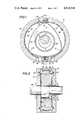
- FIG. 1is a transverse sectional view of a rotary compressor embodying the invention
- FIG. 2is an axial sectional view taken along line 2--2 of FIG. 1;
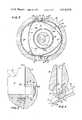
- FIG. 3is an enlarged view of a portion of FIG. 2;
- FIG. 4is a view taken along line 4--4 of FIG. 3;
- FIG. 5is a view similar to FIG. 1 but showing the compressor rotor in a different position
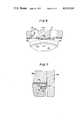
- FIG. 6is an enlarged partial view showing a modification of the structure shown in FIGS. 3 and 4;
- FIG. 7is a sectional view taken along line 7--7 of FIG. 6.
- FIGS. 1 and 2 of the drawingdisclose a rotary compressor 10 in which the inner body or rotor 12 of the compressor has a peripheral surface 14 which is a hypotrochoid preferably having three apex or nose portions 16.
- the rotor 12is rotatably journaled by a bearing 17 on the eccentric portion 18 of a shaft 20 which is coaxially supported in an outer body or housing consisting of a pair of axially-spaced end walls 22 and 24 and an intermediate peripheral wall or rotor housing 26.
- the housing walls 22, 24 and 26are suitably secured together as by bolts (not shown).
- the rotor 12has an internal gear 28 secured to one end face of the rotor and disposed in mesh with a gear 30 secured to the adjacent housing end wall 24.
- the gears 28 and 30,in effect, form the rolling circles for generating the hypotrochoid surface 14.
- the gears 28 and 30are provided with a diameter ratio of 3:2.
- the inner peripheral surface 32 of the intermediate or rotor housing 26is approximately the outer envelope of the rotor trochoidal peripheral surface 14. That is, the surface 32 is approximately the outer envelope of the various positions of the rotor peripheral surface 14 relative to the rotor housing 26.
- the resulting peripheral surface 32has two waist portions 34 which, in effect, generate the hypotrochoidal surface 14 as the rotor rotates relative to rotor housing 26. Therefore, each of the two waist portions 34, in effect, is a generating line (herein termed generating element) which extends axially across the rotor housing 26 and generates the hypotrochoid rotor surface 14 as the rotor 12 rotates relative to its rotor housing 26.
- generating lineherein termed generating element
- the rotary mechanism 10is also provided with an intake port 40 and an outlet or exhaust port 42 disposed on opposite sides of each waist portion 34 of the rotor housing.
- Each exhaust port 42preferably is provided with a check valve schematically shown at 43 to prevent reverse flow into the compressor.
- a plurality of working chambers 44are formed between the rotor 12 and rotor housing 26. Each of these chambers extend circumferentially from a rotor nose portion 16 to another nose portion or to a hypotrochoid generating element 34. If the shaft 20 rotates in a clockwise direction, as viewed in FIG. 1, the rotor 12 also rotates clockwise but at one-third the speed of the shaft.
- each half of the rotary mechanism 10 on opposite sides of a vertical plane through the generating elements or waist portions 34 of the rotor housingfunctions as a compressor.
- the rotor end facesare provided with one or more annular oil seals 46 received in grooves in the rotor end faces and urged axially by springs (not shown) against the adjacent housing end walls 22 and 24.
- the structure so far describedis conventional.
- a radially movable seal bar 50is provided at each waist portion 34 of the rotor housing to function as the hypotrochoid generating element.
- Each seal bar 50is received within a radial groove 52 extending axially across the rotor housing 26 and a spring 54 at the bottom of the groove elastically urges the seal bar 50 radially inwardly into continuous contact with the hypotrochoidal peripheral surface 14 of the rotor 12. In this way, the seal bars 50 prevent leakage across each waist portion 34 of the rotor housing between working chambers 44 on opposite sides of said waist portion.
- each working chamber 44it is necessary that seal means be provided between each rotor nose portion 16 and the inner surface 32 of the rotor housing. It is essential that this latter seal means have no mechanical interference with the seal bars 50 during passage of a rotor nose portion 16 under one of said seal bars. For this reason it is impractical to also utilize radial movable seal bars on each rotor nose portion 16 for sealing contact with the rotor housing surface 32.
- the inner surface of the housing 26is provided with a compressible liner 60 which is sufficiently thick in size so as to be elastically compressed slightly by contact with the nose portions 16 of the rotor thereby providing a seal therebetween.
- the liner 60could be made of suitable elastomeric material, for example, silicone rubber sponge-type material, and be provided with a smooth or low friction wear-resistant skin.
- a skin(not shown) could be a plastic sheet bonded to the base sponge material of the liner 60 and consisting of teflon fibers layered or interwoven with fibers of other low friction material. Examples of such woven plastic material are commercially available under the trade names Fibriloid and Fiberglide from the Transport Dynamics Division of Lear Siegler, Inc.
- the rotor housing surface 32could also be provided with labyrinth-type grooves to provide the seal between said housng surface and the rotor nose portions 16.
- the specific details of the seal between each rotor nose portion 16 and the inner surface 32 of the rotor housingform no part of this invention. It is essential, however, that some form of seal be provided between each rotor nose portion 16 and the rotor housing which does not mechanically interfere with the housing seal bars 50.
- Each housing seal bar 50preferably is provided with a rounded tip to minimize wear as this seal tip slides over the rotor surface 14.
- the seal bar 50is not always perpendicular to the rotor surface 14 and, in general, makes an angle to this surface which varies as the rotor rotates. Because of this angular variation of each seal bar 50 relative to the rotor surface and because the tip of the seal bar is rounded, the seal bar would have to shift radially in its slot 52 to maintain contact with the rotor surface if this surface were a true hypotrochoid. Such radial motion of the seal bar would be objectionable because it would involve frictional sliding of the seal bar along a side of its groove 52. Theoretically, this radial motion could be eliminated by providing the seal bar with a pointed tip. This is impractical however, since such a pointed tip would quickly wear to a blunt tip.
- each seal bar 50is rounded with a radius a and the surface 14 of the rotor 12 instead of being made a true hypotrochoid is made parallel to a theoretical or true hypotrochoid 61 generated by the point 62 which is the center of curvature of the rounded tip of its seal bar 50, the surface 14 being displaced radially inwardly of the theoretical hypotrochoid 60 by the same distance a.
- This seal tip constructionis similar to that shown in British Pat. No. 1,154,090 granted June 4, 1966 to Huf, but for a rotor having an epitrochoidal peripheral surface rather than a hypotrochoid.
- the point 62will generate a true or theoretical hypotrochoid 60 as the rotor rotates.
- the rotor surface 14is parallel to this true hypotrochoid by a distance a which is the same as the tip radius of the seal bar 50, no radial motion of the seal bar 50 is required to maintain sealing contact with the rotor surface 14 even though the angle between the seal bar 50 and rotor surface 14 changes during each rotation of the rotor.
- Some radial motion of the seal bar 50will, of course, take place in actual practice because of such factors as manufacturing tolerances and bearing clearances.
- the distance ais small and since the rotor peripheral surface 14 is parallel to a true hypotrochoid, the surface 14 is substantially a hypotrochoid.
- each seal strip 70is provided at each rotor end face.
- Each seal strip 70is received within a groove 72 in its rotor end face and a spring 74 at the bottom of the groove elastically urges the seal strip into sealing contact with the adjacent housing end wall.
- each seal strip 70is disposed close to the hypotrochoid surface 14 of the rotor and is parallel to that surface.
- each seal bar 50extending axially completely across the rotor housing 26
- a small leakage pathwould nevertheless exist between each seal bar and the side seal strip 70 through the area 76 between the end face of the rotor 12 and the adjacent housing end wall 22 or 24.
- the adjacent housing end wall 22 or 24(24 in FIG. 3) is provided with an axially movable cylindrical pin 78 which is received within a recess 80 in said housing end wall.
- a spring 82 behind each pin 78elastically urges it axially into contact with the adjacent end surface of the rotor 12.
- the adjacent portion of the rotor housing 26has a recess 84 so as not to interfere with the axial movement of the pin 78 against the end surface of the rotor.
- the end of the pin 78 facing its adjacent seal bar 50is slotted as shown at 86 to straddle the adjacent end of the seal bar.
- the slot 86preferably has substantially the same width as the groove 52 in which the seal bar 50 is received. In this way the seal bar 50 also does not interfere with axial movement of the pin 78 against the adjacent end face of the rotor 12.
- the seal bar 50preferably has an axial extension 90 extending into the slot 86 of each seal pin 78 to minimize any leakage between each seal pin 78 and its associated seal bar 50.
- Each cylindrical seal pin 78has its axis coaxial with the center of curvature 62 of the rounded tip of the seal bar 50.
- the radius b of at least the radially inner side of the seal pinis made substantially equal to the radial distance between each seal strip 70 and the true hypotrochoid 61 generated by said center of curvature 62.
- the radius bis made slightly smaller than the distance between the true hypotrochoid 61 and the seal strip 70 to provide a small clearance 92 only to avoid mechanical interference between the seal pin 78 and the seal strip 70, for example, because of manufacturing tolerances or bearing clearances.
- the small clearance 92 between the rotor seal strip 70 and the housing seal pin 78remains substantially constant in all positions of the rotor.
- the rotor seal strips 70need not be a one-piece strip.
- itmay consist of segments having overlapping joints such as shown at 94 in FIG. 4.
- FIG. 5shows the rotor 12 in a position in which one rotor nose portion 16 (the upper one in FIG. 5) is just moving past an outlet port 42. That is, the rotor 12 is in a position in which it has just completed discharge of a working chamber 44 through a port 42.
- the seal between said rotor nose portion 16 and the housing inner surface 32has almost reached the housing seal bar 50 so that the circumferential distance between their seal points is approaching a small value.
- the rotorin a Cooley-type compressor the rotor has an epitrochoidal surface which, in the minimum volume position of a working chamber, theoretically can be made to fit very close to the adjacent portion of the rotor housing.
- a significant minimum volumemust be provided between the rotor and rotor housing of a Cooley-type compressor.
- Another advantage of the compressor 10 over a compressor having a Cooley-type configurationlies in the fact that by positioning the intake and outlet ports 40 and 42 sufficiently close to a hypotrochoid generating seal bar 50, as illustrated, there is no overlap (that is, no period of simultaneous opening) of the intake and outlet ports 40 and 42 respectively to a working chamber 44.
- the left-hand working chamber 44has just moved past and is out of communication with the lower left-hand intake port 40 and has not as yet moved into communication with the upper left-hand outlet port 42. Therefore, each working chamber 44 receives its complete charge before opening to an outlet port 42. Accordingly, any flow-back, for example because of the small volume of compressed gas trapped between the check valve 43 and the rotor housing inner surface 32, does not in any way decrease the charge drawn into the working chamber through the intake port.
- FIG. 5shows alternate inlet ports 40b and alternate outlet ports 42b in the housing end wall 22 or 24 by a dot and dash outline.
- FIGS. 6 and 7For ease of understanding, the parts of FIGS. 6 and 7 corresponding to the parts of FIGS. 1-4 have been designated by the same reference numerals but with the subscript a added thereto.
- each seal element 94is bonded to each end housing (only end housing 24a is illustrated in FIGS. 6-7) under each generating element or waist portion 34a of the rotor housing 26a.
- Each seal element 94has a thickness such that it is elastically compressed between the adjacent end face of the rotor 12a and the end housing 24a.
- the radially inner surface of the seal element 94preferably has substantially the same radius of curvature and center of curvature as described for the seal pins 78.
- the elastically compressible seal elements 94 of FIGS. 6-7function to seal the same leakage area as the seal pins 78 of FIGS. 1-4.
- FIGS. 6 and 7also differs from that of FIGS. 1-4 in that the metal or rigid seal bars which in FIGS. 1-4 are elastically urged into contact with the rotor hypotrochoid surface, are replaced by having the elastomeric liner 60a extend across the waist portions 34a of the rotor housing 26a.
- the portion of the liner 60a at each waist portion 34afunctions as the generating element for the hypotrochoid surface 14a of the rotor 12a and is urged by its own elasticity into continuous contact with the rotor surface 14a as the rotor rotates.
- the liner 60ais made sufficiently thick so as to be continuously compressed by the nose portions of the rotor 12a and so as to be continuously compressed by the rotor surface 14a at each of the waist portions 34a of the rotor housing 26a. It is clear, therefore, that the portion of the elastically compressible liner 60a at each waist portion of the rotor housing performs the same sealing function in FIGS. 6 and 7 as do the sealing bars 50 in FIGS. 1-4.
- compressible seal elements 94 and the axially movable seal pins 78each could be used in combination with either the hypotrochoid generating seal bars 50 of FIGS. 1--4 or with the compressible waist portions 34a of FIGS. 6-7.
- FIGS. 6-7has the disadvantage compared to that of FIGS. 1-4, in that the portion of the compressible liner 60a at the rotor housing waist portions 34a is subject to continuous wear contact with the rotor hypotrochoid surface 14a, whereas the balance of this liner is only intermittently subject to wear from the rotor nose portions.
- the construction of FIGS. 6-7has the advantage of being simpler and therefore for certain applications may be preferred to that of FIGS. 1-4.
- the inventionhas been described in terms of compressor operation, the invention is equally applicable to expansion engines. Also, the invention is not limited to the specific geometric configuration illustrated.
- the hypotrochoid surface 14a of the rotorcould have a different number of nose portions by changing the diameters of the rolling circles from which the hypotrochoid is generated.
Landscapes
- Engineering & Computer Science (AREA)
- Mechanical Engineering (AREA)
- General Engineering & Computer Science (AREA)
- Applications Or Details Of Rotary Compressors (AREA)
Abstract
Description
Claims (1)
Priority Applications (1)
| Application Number | Priority Date | Filing Date | Title |
|---|---|---|---|
| US05/638,513US4018548A (en) | 1975-12-08 | 1975-12-08 | Rotary trochoidal compressor |
Applications Claiming Priority (1)
| Application Number | Priority Date | Filing Date | Title |
|---|---|---|---|
| US05/638,513US4018548A (en) | 1975-12-08 | 1975-12-08 | Rotary trochoidal compressor |
Publications (1)
| Publication Number | Publication Date |
|---|---|
| US4018548Atrue US4018548A (en) | 1977-04-19 |
Family
ID=24560345
Family Applications (1)
| Application Number | Title | Priority Date | Filing Date |
|---|---|---|---|
| US05/638,513Expired - LifetimeUS4018548A (en) | 1975-12-08 | 1975-12-08 | Rotary trochoidal compressor |
Country Status (1)
| Country | Link |
|---|---|
| US (1) | US4018548A (en) |
Cited By (32)
| Publication number | Priority date | Publication date | Assignee | Title |
|---|---|---|---|---|
| FR2366453A1 (en)* | 1977-07-08 | 1978-04-28 | Kunieda Eiichi | Sealing strip for rotor of rotary engine - uses leaf spring in bottom of groove to maintain contact with cylinder bore |
| US4150926A (en)* | 1977-01-10 | 1979-04-24 | Borsig Gmbh | Rotary piston compressor with transfer flow pockets in housing |
| US4395206A (en)* | 1981-04-28 | 1983-07-26 | Trochoid Power Corporation | Seal compensated geometry rotary motion device |
| GB2215403A (en)* | 1988-03-10 | 1989-09-20 | Hydrovane Compressor | Rotary compressors |
| US5271364A (en)* | 1992-09-04 | 1993-12-21 | Snyder Duane P | Rotary internal combustion engine |
| US5295814A (en)* | 1989-10-04 | 1994-03-22 | Archimedes Associates Inc. | Trochoidal rotary piston machine with piston follow-up mechanism |
| US5391067A (en)* | 1993-07-20 | 1995-02-21 | Saunders; James E. | Rotary fluid displacement device |
| US6187167B1 (en) | 1998-07-13 | 2001-02-13 | Eastman Kodak Company | Recovery of metal from solution |
| US6207037B1 (en) | 1998-07-13 | 2001-03-27 | Eastman Kodak Company | Recovery of metal from solution |
| US6520754B2 (en) | 2001-01-22 | 2003-02-18 | Randell Technologies Inc. | Compressor unit for refrigeration |
| US20050196311A1 (en)* | 2004-03-02 | 2005-09-08 | Krayer William L. | Turntable with turning guide |
| US20050196310A1 (en)* | 2004-03-02 | 2005-09-08 | Turn The Corner, Llc | Turntable with gerotor |
| US20080056924A1 (en)* | 2006-06-30 | 2008-03-06 | Thermo Fan | Volumetric efficiency in a charge cooled or air cooled wankel rotary engine |
| US20110070032A1 (en)* | 2009-09-23 | 2011-03-24 | Scott Raymond Frazier | Underwater compressed fluid energy storage system |
| US20140069367A1 (en)* | 2003-06-27 | 2014-03-13 | Power Source Techologies, Inc. | Dual tip seals for a rotary engine |
| WO2012151423A3 (en)* | 2011-05-05 | 2014-05-08 | Power Source Technologies, Inc. | Dual tip seals for a rotary engine |
| US8749079B1 (en)* | 2011-04-01 | 2014-06-10 | The United States Of America As Represented By The Secretary Of The Navy | Integrated wankel expander-alternator |
| US8794941B2 (en) | 2010-08-30 | 2014-08-05 | Oscomp Systems Inc. | Compressor with liquid injection cooling |
| GB2528309A (en)* | 2014-07-17 | 2016-01-20 | David Walker Garside | Epitrochoidal type compressor |
| US9267504B2 (en) | 2010-08-30 | 2016-02-23 | Hicor Technologies, Inc. | Compressor with liquid injection cooling |
| US10087758B2 (en) | 2013-06-05 | 2018-10-02 | Rotoliptic Technologies Incorporated | Rotary machine |
| US20190085843A1 (en)* | 2017-09-20 | 2019-03-21 | Haselmeier Ag | Rotary pump driven medicament delivery device |
| US10837444B2 (en) | 2018-09-11 | 2020-11-17 | Rotoliptic Technologies Incorporated | Helical trochoidal rotary machines with offset |
| US10871161B2 (en) | 2017-04-07 | 2020-12-22 | Stackpole International Engineered Products, Ltd. | Epitrochoidal vacuum pump |
| US11802558B2 (en) | 2020-12-30 | 2023-10-31 | Rotoliptic Technologies Incorporated | Axial load in helical trochoidal rotary machines |
| US11815094B2 (en) | 2020-03-10 | 2023-11-14 | Rotoliptic Technologies Incorporated | Fixed-eccentricity helical trochoidal rotary machines |
| US12110796B1 (en)* | 2023-07-13 | 2024-10-08 | Pratt & Whitney Canada Corp. | Seal assembly for a rotary engine housing |
| US12116925B1 (en) | 2024-06-05 | 2024-10-15 | Dale Warner | Rotary engine with dual axis rotor rotation |
| US12146492B2 (en) | 2021-01-08 | 2024-11-19 | Rotoliptic Technologies Incorporated | Helical trochoidal rotary machines with improved solids handling |
| US12331744B2 (en)* | 2023-06-14 | 2025-06-17 | Foon Seto | Air compressor |
| US12352268B2 (en) | 2021-01-08 | 2025-07-08 | Rotoliptic Technologies Incorporated | Pumps, compressors, and expanders with a teardrop-shaped rotor |
| US12435661B1 (en)* | 2024-04-08 | 2025-10-07 | Pratt & Whitney Canada Corp. | Rotary engine with seal having shield and elastomeric member |
Citations (8)
| Publication number | Priority date | Publication date | Assignee | Title |
|---|---|---|---|---|
| GB583035A (en)* | 1943-08-20 | 1946-12-05 | Bernard Maillard | A rotary machine generating variable volumes |
| US3185386A (en)* | 1960-09-20 | 1965-05-25 | Renault | Packing devices comprising fixed and movable elements for rotary engines |
| US3226013A (en)* | 1964-05-04 | 1965-12-28 | Toyota Motor Co Ltd | Rotary machine |
| US3369739A (en)* | 1966-04-30 | 1968-02-20 | Kloeckner Humboldt Deutz Ag | Rotary piston internal combustion engine, especially circular piston internal combustion engine |
| US3387772A (en)* | 1965-02-04 | 1968-06-11 | Leybold Heraeus Gmbh & Co Kg | Rotary vacuum pump |
| US3764239A (en)* | 1970-12-05 | 1973-10-09 | Dornier System Gmbh | Rotary piston engine with trochoidal construction |
| GB1350728A (en)* | 1972-06-15 | 1974-04-24 | Dornier System Gmbh | Trochoid-type rotary piston machine |
| US3883276A (en)* | 1972-10-20 | 1975-05-13 | Volkswagenwerk Ag | Discharge arrangement for the exhaust gas from the work areas of a rotary piston combustion engine |
- 1975
- 1975-12-08USUS05/638,513patent/US4018548A/ennot_activeExpired - Lifetime
Patent Citations (8)
| Publication number | Priority date | Publication date | Assignee | Title |
|---|---|---|---|---|
| GB583035A (en)* | 1943-08-20 | 1946-12-05 | Bernard Maillard | A rotary machine generating variable volumes |
| US3185386A (en)* | 1960-09-20 | 1965-05-25 | Renault | Packing devices comprising fixed and movable elements for rotary engines |
| US3226013A (en)* | 1964-05-04 | 1965-12-28 | Toyota Motor Co Ltd | Rotary machine |
| US3387772A (en)* | 1965-02-04 | 1968-06-11 | Leybold Heraeus Gmbh & Co Kg | Rotary vacuum pump |
| US3369739A (en)* | 1966-04-30 | 1968-02-20 | Kloeckner Humboldt Deutz Ag | Rotary piston internal combustion engine, especially circular piston internal combustion engine |
| US3764239A (en)* | 1970-12-05 | 1973-10-09 | Dornier System Gmbh | Rotary piston engine with trochoidal construction |
| GB1350728A (en)* | 1972-06-15 | 1974-04-24 | Dornier System Gmbh | Trochoid-type rotary piston machine |
| US3883276A (en)* | 1972-10-20 | 1975-05-13 | Volkswagenwerk Ag | Discharge arrangement for the exhaust gas from the work areas of a rotary piston combustion engine |
Cited By (50)
| Publication number | Priority date | Publication date | Assignee | Title |
|---|---|---|---|---|
| US4150926A (en)* | 1977-01-10 | 1979-04-24 | Borsig Gmbh | Rotary piston compressor with transfer flow pockets in housing |
| FR2366453A1 (en)* | 1977-07-08 | 1978-04-28 | Kunieda Eiichi | Sealing strip for rotor of rotary engine - uses leaf spring in bottom of groove to maintain contact with cylinder bore |
| US4395206A (en)* | 1981-04-28 | 1983-07-26 | Trochoid Power Corporation | Seal compensated geometry rotary motion device |
| GB2215403A (en)* | 1988-03-10 | 1989-09-20 | Hydrovane Compressor | Rotary compressors |
| US5295814A (en)* | 1989-10-04 | 1994-03-22 | Archimedes Associates Inc. | Trochoidal rotary piston machine with piston follow-up mechanism |
| US5271364A (en)* | 1992-09-04 | 1993-12-21 | Snyder Duane P | Rotary internal combustion engine |
| US5391067A (en)* | 1993-07-20 | 1995-02-21 | Saunders; James E. | Rotary fluid displacement device |
| US6207037B1 (en) | 1998-07-13 | 2001-03-27 | Eastman Kodak Company | Recovery of metal from solution |
| US6187167B1 (en) | 1998-07-13 | 2001-02-13 | Eastman Kodak Company | Recovery of metal from solution |
| US6520754B2 (en) | 2001-01-22 | 2003-02-18 | Randell Technologies Inc. | Compressor unit for refrigeration |
| US20140069367A1 (en)* | 2003-06-27 | 2014-03-13 | Power Source Techologies, Inc. | Dual tip seals for a rotary engine |
| US9464567B2 (en)* | 2003-06-27 | 2016-10-11 | Power Source Technologies, Inc. | Dual tip seals for a rotary engine |
| US20050196311A1 (en)* | 2004-03-02 | 2005-09-08 | Krayer William L. | Turntable with turning guide |
| US20050196310A1 (en)* | 2004-03-02 | 2005-09-08 | Turn The Corner, Llc | Turntable with gerotor |
| US7137797B2 (en) | 2004-03-02 | 2006-11-21 | Krayer William L | Turntable with gerotor |
| US7147445B2 (en) | 2004-03-02 | 2006-12-12 | Krayer William L | Turntable with turning guide |
| US20080056924A1 (en)* | 2006-06-30 | 2008-03-06 | Thermo Fan | Volumetric efficiency in a charge cooled or air cooled wankel rotary engine |
| US9139974B2 (en)* | 2009-09-23 | 2015-09-22 | Bright Energy Storage Technologies, Llp | Underwater compressed fluid energy storage system |
| US20110070032A1 (en)* | 2009-09-23 | 2011-03-24 | Scott Raymond Frazier | Underwater compressed fluid energy storage system |
| US9719514B2 (en) | 2010-08-30 | 2017-08-01 | Hicor Technologies, Inc. | Compressor |
| US9856878B2 (en) | 2010-08-30 | 2018-01-02 | Hicor Technologies, Inc. | Compressor with liquid injection cooling |
| US10962012B2 (en) | 2010-08-30 | 2021-03-30 | Hicor Technologies, Inc. | Compressor with liquid injection cooling |
| US9267504B2 (en) | 2010-08-30 | 2016-02-23 | Hicor Technologies, Inc. | Compressor with liquid injection cooling |
| US8794941B2 (en) | 2010-08-30 | 2014-08-05 | Oscomp Systems Inc. | Compressor with liquid injection cooling |
| US8749079B1 (en)* | 2011-04-01 | 2014-06-10 | The United States Of America As Represented By The Secretary Of The Navy | Integrated wankel expander-alternator |
| WO2012151423A3 (en)* | 2011-05-05 | 2014-05-08 | Power Source Technologies, Inc. | Dual tip seals for a rotary engine |
| US10087758B2 (en) | 2013-06-05 | 2018-10-02 | Rotoliptic Technologies Incorporated | Rotary machine |
| US11506056B2 (en) | 2013-06-05 | 2022-11-22 | Rotoliptic Technologies Incorporated | Rotary machine |
| US10844720B2 (en) | 2013-06-05 | 2020-11-24 | Rotoliptic Technologies Incorporated | Rotary machine with pressure relief mechanism |
| GB2528309B (en)* | 2014-07-17 | 2016-10-19 | Walker Garside David | Epitrochoidal type compressor |
| GB2528309A (en)* | 2014-07-17 | 2016-01-20 | David Walker Garside | Epitrochoidal type compressor |
| US10871161B2 (en) | 2017-04-07 | 2020-12-22 | Stackpole International Engineered Products, Ltd. | Epitrochoidal vacuum pump |
| JP2020534469A (en)* | 2017-09-20 | 2020-11-26 | ハーゼルマイアー アーゲー | Rotary pump driven drug delivery device |
| US20190085843A1 (en)* | 2017-09-20 | 2019-03-21 | Haselmeier Ag | Rotary pump driven medicament delivery device |
| US11566618B2 (en)* | 2017-09-20 | 2023-01-31 | Medico Invest Ag | Rotary pump driven medicament delivery device |
| US10844859B2 (en) | 2018-09-11 | 2020-11-24 | Rotoliptic Technologies Incorporated | Sealing in helical trochoidal rotary machines |
| US10837444B2 (en) | 2018-09-11 | 2020-11-17 | Rotoliptic Technologies Incorporated | Helical trochoidal rotary machines with offset |
| US11306720B2 (en) | 2018-09-11 | 2022-04-19 | Rotoliptic Technologies Incorporated | Helical trochoidal rotary machines |
| US11499550B2 (en) | 2018-09-11 | 2022-11-15 | Rotoliptic Technologies Incorporated | Sealing in helical trochoidal rotary machines |
| US11608827B2 (en) | 2018-09-11 | 2023-03-21 | Rotoliptic Technologies Incorporated | Helical trochoidal rotary machines with offset |
| US11988208B2 (en) | 2018-09-11 | 2024-05-21 | Rotoliptic Technologies Incorporated | Sealing in helical trochoidal rotary machines |
| US11815094B2 (en) | 2020-03-10 | 2023-11-14 | Rotoliptic Technologies Incorporated | Fixed-eccentricity helical trochoidal rotary machines |
| US11802558B2 (en) | 2020-12-30 | 2023-10-31 | Rotoliptic Technologies Incorporated | Axial load in helical trochoidal rotary machines |
| US12146492B2 (en) | 2021-01-08 | 2024-11-19 | Rotoliptic Technologies Incorporated | Helical trochoidal rotary machines with improved solids handling |
| US12352268B2 (en) | 2021-01-08 | 2025-07-08 | Rotoliptic Technologies Incorporated | Pumps, compressors, and expanders with a teardrop-shaped rotor |
| US12331744B2 (en)* | 2023-06-14 | 2025-06-17 | Foon Seto | Air compressor |
| US12110796B1 (en)* | 2023-07-13 | 2024-10-08 | Pratt & Whitney Canada Corp. | Seal assembly for a rotary engine housing |
| US12435661B1 (en)* | 2024-04-08 | 2025-10-07 | Pratt & Whitney Canada Corp. | Rotary engine with seal having shield and elastomeric member |
| US20250314196A1 (en)* | 2024-04-08 | 2025-10-09 | Pratt & Whitney Canada Corp. | Rotary engine with seal having shield and elastomeric member |
| US12116925B1 (en) | 2024-06-05 | 2024-10-15 | Dale Warner | Rotary engine with dual axis rotor rotation |
Similar Documents
| Publication | Publication Date | Title |
|---|---|---|
| US4018548A (en) | Rotary trochoidal compressor | |
| US4012180A (en) | Rotary compressor with labyrinth sealing | |
| US4028021A (en) | Rotary trochoidal compressor with compressible sealing | |
| CA2672332C (en) | A rotary device | |
| US4005951A (en) | Rotary vane engine with orbiting inner and outer members | |
| US4714417A (en) | Internal axis single-rotation machine with intermeshing internal and external rotors | |
| GB1486946A (en) | Rotary engines and pumps | |
| US4437823A (en) | Rotary machine with an axially moving partition | |
| US4395206A (en) | Seal compensated geometry rotary motion device | |
| US3171590A (en) | Oil seal construction for rotary combustion engines | |
| US3852003A (en) | Pressure-sealed compressor | |
| US3930767A (en) | Circular rotor side seal for rotary machines | |
| US4137024A (en) | Rotor for rotary piston mechanism | |
| US3193188A (en) | Rotor and seal construction for rotary mechanisms | |
| GB2044357A (en) | Rotary positive-displacement fluid-machines | |
| US3990817A (en) | Rotary combustion engine having a modified trochoid | |
| US4548560A (en) | Seal system in rotary engine | |
| US3799126A (en) | Rotary machines | |
| US4861244A (en) | Spiral displacement machine with concave circular arcs sealingly engaging circular steps | |
| JPH07109981A (en) | Scroll fluid machinery | |
| US3827835A (en) | Low speed rotary fluid apparatus with elastic sealing liner | |
| US3952709A (en) | Orbital vane rotary machine | |
| US3758243A (en) | Rotary machine apex seal | |
| US5944499A (en) | Rotor-type pump having a communication passage interconnecting working-fluid chambers | |
| US4466335A (en) | Sealing for variable volume device |
Legal Events
| Date | Code | Title | Description |
|---|---|---|---|
| AS | Assignment | Owner name:JOHN DEERE TECHNOLOGIES INTERNATIONAL, INC., JOHN Free format text:ASSIGNMENT OF ASSIGNORS INTEREST.;ASSIGNOR:CURTISS-WRIGHT CORPORATION, A CORP. OF DE;REEL/FRAME:005646/0925 Effective date:19840223 | |
| AS | Assignment | Owner name:SNYDER, SHERYL K. Free format text:SECURITY INTEREST;ASSIGNOR:ROTARY POWER INTERNATIONAL, INC., A CORPORATION OF DE;REEL/FRAME:006027/0113 Effective date:19920220 Owner name:LOEB PARTNERS CORPORATION Free format text:SECURITY INTEREST;ASSIGNOR:ROTARY POWER INTERNATIONAL, INC., A CORPORATION OF DE;REEL/FRAME:006027/0122 Effective date:19920220 Owner name:SNYDER, LARRY L. Free format text:SECURITY INTEREST;ASSIGNOR:ROTARY POWER INTERNATIONAL, INC., A CORPORATION OF DE;REEL/FRAME:006027/0113 Effective date:19920220 | |
| AS | Assignment | Owner name:ROTARY POWER INTERNATIONAL, INC., NEW JERSEY Free format text:ASSIGNMENT OF ASSIGNORS INTEREST.;ASSIGNOR:JOHN DEERE TECHNOLOGIES INTERNATIONAL, INC.;REEL/FRAME:006031/0870 Effective date:19911231 |