US4014387A - Apparatus and process for drawing water from a water-bearing strata - Google Patents
Apparatus and process for drawing water from a water-bearing strataDownload PDFInfo
- Publication number
- US4014387A US4014387AUS05/540,002US54000275AUS4014387AUS 4014387 AUS4014387 AUS 4014387AUS 54000275 AUS54000275 AUS 54000275AUS 4014387 AUS4014387 AUS 4014387A
- Authority
- US
- United States
- Prior art keywords
- water
- well
- pump
- permeable
- cylindrical
- Prior art date
- Legal status (The legal status is an assumption and is not a legal conclusion. Google has not performed a legal analysis and makes no representation as to the accuracy of the status listed.)
- Expired - Lifetime
Links
- XLYOFNOQVPJJNP-UHFFFAOYSA-NwaterSubstancesOXLYOFNOQVPJJNP-UHFFFAOYSA-N0.000titleclaimsabstractdescription78
- 238000000034methodMethods0.000titleclaimsdescription8
- 230000008569processEffects0.000titleclaimsdescription7
- 239000004576sandSubstances0.000claimsabstractdescription20
- 239000008187granular materialSubstances0.000claimsabstractdescription11
- 239000002245particleSubstances0.000claimsdescription6
- 230000035699permeabilityEffects0.000claimsdescription5
- 230000009471actionEffects0.000claimsdescription2
- 238000005086pumpingMethods0.000claimsdescription2
- 230000004048modificationEffects0.000description7
- 238000012986modificationMethods0.000description7
- 239000007787solidSubstances0.000description7
- 210000002445nippleAnatomy0.000description5
- 239000000463materialSubstances0.000description4
- 230000000694effectsEffects0.000description2
- 239000004033plasticSubstances0.000description2
- 229910000831SteelInorganic materials0.000description1
- 238000010276constructionMethods0.000description1
- 238000005553drillingMethods0.000description1
- 230000003628erosive effectEffects0.000description1
- 238000001914filtrationMethods0.000description1
- 239000003673groundwaterSubstances0.000description1
- 238000004519manufacturing processMethods0.000description1
- 239000002184metalSubstances0.000description1
- 239000011236particulate materialSubstances0.000description1
- 230000002028prematureEffects0.000description1
- 230000000750progressive effectEffects0.000description1
- 230000008439repair processEffects0.000description1
- 230000000630rising effectEffects0.000description1
- 239000011435rockSubstances0.000description1
- 238000007789sealingMethods0.000description1
- 239000002689soilSubstances0.000description1
- 239000010959steelSubstances0.000description1
- 229920002994synthetic fiberPolymers0.000description1
- 238000003466weldingMethods0.000description1
- 239000002349well waterSubstances0.000description1
- 235000020681well waterNutrition0.000description1
Images

Classifications
- E—FIXED CONSTRUCTIONS
- E03—WATER SUPPLY; SEWERAGE
- E03B—INSTALLATIONS OR METHODS FOR OBTAINING, COLLECTING, OR DISTRIBUTING WATER
- E03B3/00—Methods or installations for obtaining or collecting drinking water or tap water
- E03B3/06—Methods or installations for obtaining or collecting drinking water or tap water from underground
- E03B3/08—Obtaining and confining water by means of wells
- E03B3/16—Component parts of wells
- E03B3/18—Well filters
- E03B3/20—Well filters of elements of special shape
- E—FIXED CONSTRUCTIONS
- E21—EARTH OR ROCK DRILLING; MINING
- E21B—EARTH OR ROCK DRILLING; OBTAINING OIL, GAS, WATER, SOLUBLE OR MELTABLE MATERIALS OR A SLURRY OF MINERALS FROM WELLS
- E21B43/00—Methods or apparatus for obtaining oil, gas, water, soluble or meltable materials or a slurry of minerals from wells
- E21B43/02—Subsoil filtering
- E21B43/08—Screens or liners
- E21B43/082—Screens comprising porous materials, e.g. prepacked screens
- E—FIXED CONSTRUCTIONS
- E21—EARTH OR ROCK DRILLING; MINING
- E21B—EARTH OR ROCK DRILLING; OBTAINING OIL, GAS, WATER, SOLUBLE OR MELTABLE MATERIALS OR A SLURRY OF MINERALS FROM WELLS
- E21B43/00—Methods or apparatus for obtaining oil, gas, water, soluble or meltable materials or a slurry of minerals from wells
- E21B43/02—Subsoil filtering
- E21B43/08—Screens or liners
- E21B43/086—Screens with preformed openings, e.g. slotted liners
Definitions
- the present inventionrelates to the drawing of water from a well bored into water-bearing strata, more particularly, to an apparatus and process for withdrawing such water in a sand-free condition.
- the water obtained from drilled wellsgenerally has entrained sand and such wells must be replaced by new wells after being in operation for only a few years.
- the pumps operating in such wellsare subjected to a very great wear because of the eroding action caused by the sand contained in the water passing through the pump.
- the pumpsrequire high repair costs and must be replaced after a relatively short operating life.
- the water-bearing stratavary from one another such strata are susceptible to a progressive decay or shrinkage. The continuous withdrawal of sand from the strata may cause a sinking of the soil above the strata since the strata fails to fully support the surrounding earth.
- a process for drawing water free of sand from a well drilled into a water-bearing stratamay comprise the steps of flowing the water from water-bearing strata into a perforated wall of the well. The water is then flowed through a permeable body and subsequently the water is pumped from the well.
- an apparatusmay comprise a perforated tubular filter element defining a well wall and a cylindrical permeable body disposed concentrically within the well wall. The lower end of the body is closed and the upper end is open and connected to a pump.
- the cylindrical bodymay comprise concentric outer and inner slotted cylinders with a granulate defining a permeable body or a permeable cylinder between the concentric tubes.
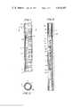
- FIG. 1is an elevational view partially in section of an element according to the present invention for suction current control
- FIG. 2is a sectional view taken along the line A--A of FIG. 1;
- FIG. 3is a longitudinal sectional view of a well incorporating the suction current control element of the present invention
- FIG. 4is a portion of the view of FIG. 3 and showing a modification of the present invention
- FIG. 5is a portion of a view of FIG. 4 in enlarged scale and showing still another modification.
- FIG. 6is a view similar to that of FIG. 3 and illustrating a suction control element according to the present invention comprising a plurality of elements.
- a permeable cylindrical body closed on its lower endis spaced concentrically in the interior of the well below the pump and this permeable cylindrical body functions to control the suction current.
- the suction current or flow of water horizontally in the wellis kept away from the water-bearing strata and the pumping action of the pump is distributed uniformly over a predetermined length of the perforated well wall.
- the normal flow of water from water-bearing sandsis approximately 5 millimeters per second and thus without any suction or intake force by the pump that quantity of water will seep into the well. Thus quantity of water will correspond to the maximum quantity of water discharged by the pump.
- the current control of the permeable bodyis selected to have such a porosity or permeability that this quantity of water to be pumped can flow into the interior of the current control element without any force.
- the rate of flow of the waterthus corresponds to the characteristics of the pump.
- suction current control elementThe required total length of such a suction current control element will depend on the characteristics of the well and the characteristics of the pump and can be readily calculated on the basis of this technical data.
- FIG. 1there is illustrated a suction current control element according to the present invention which comprises a pair of concentric slotted tubes 1 and 2 and a granulate 3 having a certain permeability filled between the tubes.
- the inner tube 1is formed of a suitable synthetic plastic material such as PVC with a smooth inner wall and is provided with a plurality of transverse slots 1a.
- a ring 4 also of PVCis mounted on the outside of the upper end of the inner tube 1 to provide a connecting nipple.
- the inside of the ring 4is smooth and is not provided with any slots.
- the lower end of the tube 1functions as a thrust bearing for the connecting nipple of the next succeeding element to be connected thereto but not shown in the drawing.
- the shaped nipple 4is provided with a plurality of threaded bores 5.
- the number of bores 5will depend on the diameter of the ring 4. If desirable, the bores may be reinforced by metal nuts embedded in the ring 4 and surrounding the bores.
- the inner tube 1is surrounded by a concentrically disposed outer tube 2 preferably of the same material such as PVC but having a somewhat greater diameter and also provided with a number of transverse slots 2a.
- the slotsmay have a maximum width of about 1 millimeter.
- the lower end of the outer tube 2forms a loosely fitting connecting sleeve to the nipple of the next lower succeeding element.
- the internal diameter of outer tube 2is about 50 millimeters greater than the outer diameter of the inner tube 1 and the space between the tubes is filled by a granulated filling 3 of a hard material such as plastic synthetic material granulate, washed grit particles or similar materials.
- the granulate material 3may comprise particles all of the same size or may comprise particles of a plurality of different sizes.
- the granulate fill 3is enclosed between the tubes 1 and 2 by closure rings 6 and 7.
- the connecting sleeve portion on the bottom of the outer tube 2is provided with a plurality of bores 8 to receive metallic screws necessary for connecting to the nipple.
- the upper end of the outer tubeis provided with a securing ring 9.
- a complete suction current control elementis illustrated in a drilled well in FIG. 3.
- the well casing from the ground surface of the terrain to the water-bearing stratacomprises solid steel tubes 10 to which the well filters 11 or perforated tubular elements are connected by threaded connections or by welding.
- the perforated sections 11are provided with relatively wide slots 11a.
- a pump 12is positioned in the well and is mounted concentrically within the well casing 10 by means of a guide 13.
- the individual elements of the suction current control elementare designated at 14-19 and begin below the pump 12 and are preferably connected directly to the pump as shown in the drawing.
- Centering guides 20are provided at the connections between the individual control elements 14-19 so that the entire suction current control unit is positioned concentrically within the well casing. The concentric positioning of the unit assures that its function will be performed properly.
- the lower end of the suction current control elementis closed at 21 and the lower end is also provided with a centering guide 22.
- the connection of the individual control elements in the wellis facilitated and obtained by the locking ring 9 at the upper end of the control element as shown in FIG. 1.
- the well casing 10 and 11is surrounded by large-sized particles such as rocks or suitable particulate material indicated at 23 to retain and hold back the water-bearing fine sand 24.
- the concentric positioning of the control element within the wellenables the space between the interior of the well casing and the outer wall of the suction current control unit 14-19 to remain free of sand during the time that the water is being drawn by the pump 12.
- the suction current control element according to the present inventionis shown in FIG. 4 as being used in conjunction with a submersible pump in a drilled well.
- a multistage pump 25 having an electric motor 26 and a suction or intake opening 27is surrounded by a cylindrical casing or envelope 28 in such a manner that an annular space is formed between the pump 25-27 and the casing. This space enables the water which is to be pumped to reach the suction opening 27 of the pump from below.
- the casing 28has at its lower end a conical member 28a which reduces the diameter of the casing and connects to a connection 30 for the suction current control element 14-19.
- the pump 25-27is positioned within the solid portion 10 of the well casing and the first element 14 of the suction control element is at the same depth as the first perforated portion 11 of the casing. Water is pumped upwardly from the pump through a discharge pipe indicated at 28b and the electrical cable for supplying energy to the pump is indicated at 31.
- a perforated well wall casing 32 of a relatively small diameterconsists of a plurality of such casing elements connected end-to-end which stand upon the bottom of the bore of the well within the solid well casing portion indicated at 33.
- the space 34 formed between the perforated casing 32 and the solid casing 33is sealed by means of a plate 35 positioned on the upper end of the perforated casing 32 to form a carrier or mounting structure for the suction current control unit 14-19.
- a plate 35has a central circular opening therein for loosely receiving a connecting tube 36.
- a further plate 37 also having a circular opening thereinis welded to the upper end of the connecting tube 36 and is provided with a bracket 38 by means of which the unit can be lowered or raised.
- a rubber sleeve 39Positioned between the two plates 35 and 37 is a rubber sleeve 39 which may be in the form of a hose. Attached to the connecting tube 36 is the uppermost element 14 of the suction current control unit and the weight of this unit loads the rubber sleeve so that a lateral sealing is produced with respect to the solid casing portion 33 of the well. While not shown in this figure, the pump is freely suspended in the solid well casing portion 33 of the well.
- FIG. 6illustrates schematically the operation of a suction current control element in accordance with the present invention.
- Nine elements 40-48are interconnected end-to-end with the necessary centering guides to form a complete suction current control unit which is then connected to a pump 12 having a capacity of, for example, 40 liters per second.
- Each of the individual elements 40-48receives a free flow of water of 4.5 liters per second so that a total of 40.5 liters of water per second are available to the pump in the interior of the control unit.
- any turbulence which may be produced by the suction effect of the pumpis limited to this interior space of the well and is not propogated through the openings of the perforated well casing outwardly into the water-bearing strata where it might cause sand to flow into the well.
- the water rising within the wellcan thus flow in uniformly over the entire length of the perforated wall of the well which is opposite to the suction current control.
- An increased flow of water from the uppermost water-bearing strata which lies next to the suction opening of the pump and which might lead to an increased entraining of sand in the wateris thus avoided.
- the wateris thus also withdrawn from the lower lying water bearing strata.
- the present apparatusis not limited to the embodiments and modifications as disclosed herein.
- another body of a certain permeability or porositycan also be employed instead of utilizing two concentric tubes with a granulate filling therebetween.
- a cylindrical body of a certain porositymay be used without the inner and outer concentric tubes in the event that the cylindrical body has sufficient rigidity and structural strength.
- the present inventionhas disclosed a method and apparatus for withdrawing water from a water-bearing strata without there being a high content of sand in the water.
- the drawing of sand-free waternot only significantly lengthens the life of the pumps used to pump water from the well but also avoids the danger of subsistence of the ground surrounding the well because of the withdrawal of sand from the water-bearing strata.
- connectionwhen the well deviates from the vertical the several elements can be interconnected by flexible plug and sleeve connections. Such a connection also facilitates the transport of the elements from well to well.
- the connections between the individual elementsmay have a sufficient degree of flexibility depending upon the path taken by the well instead of the rigid connections disclosed herein.
Landscapes
- Engineering & Computer Science (AREA)
- Life Sciences & Earth Sciences (AREA)
- Geology (AREA)
- Mining & Mineral Resources (AREA)
- Environmental & Geological Engineering (AREA)
- Geochemistry & Mineralogy (AREA)
- General Life Sciences & Earth Sciences (AREA)
- Physics & Mathematics (AREA)
- Fluid Mechanics (AREA)
- Chemical & Material Sciences (AREA)
- Dispersion Chemistry (AREA)
- Public Health (AREA)
- Water Supply & Treatment (AREA)
- Hydrology & Water Resources (AREA)
- Health & Medical Sciences (AREA)
- Structures Of Non-Positive Displacement Pumps (AREA)
- Investigation Of Foundation Soil And Reinforcement Of Foundation Soil By Compacting Or Drainage (AREA)
- Details Of Reciprocating Pumps (AREA)
- Filtration Of Liquid (AREA)
- Extraction Or Liquid Replacement (AREA)
- Filtering Materials (AREA)
- Crushing And Grinding (AREA)
Abstract
Description
Claims (10)
Applications Claiming Priority (2)
| Application Number | Priority Date | Filing Date | Title |
|---|---|---|---|
| DE19742401327DE2401327B2 (en) | 1974-01-11 | 1974-01-11 | METHOD OF DISTRIBUTING THE AMOUNT OF WATER DRAWN IN A WELL AND DEVICE FOR CARRYING OUT THE METHOD |
| DT2401327 | 1974-01-11 |
Publications (1)
| Publication Number | Publication Date |
|---|---|
| US4014387Atrue US4014387A (en) | 1977-03-29 |
Family
ID=5904634
Family Applications (1)
| Application Number | Title | Priority Date | Filing Date |
|---|---|---|---|
| US05/540,002Expired - LifetimeUS4014387A (en) | 1974-01-11 | 1975-01-10 | Apparatus and process for drawing water from a water-bearing strata |
Country Status (27)
| Country | Link |
|---|---|
| US (1) | US4014387A (en) |
| JP (1) | JPS50102161A (en) |
| AR (1) | AR221999A1 (en) |
| AT (1) | AT354943B (en) |
| BE (1) | BE824311A (en) |
| BR (1) | BR7500143A (en) |
| CA (1) | CA1024064A (en) |
| CS (1) | CS208171B2 (en) |
| DD (1) | DD115731A5 (en) |
| DE (1) | DE2401327B2 (en) |
| DK (1) | DK661574A (en) |
| EG (1) | EG11533A (en) |
| ES (1) | ES433729A1 (en) |
| FI (1) | FI361374A7 (en) |
| FR (1) | FR2257743B1 (en) |
| GB (1) | GB1453271A (en) |
| HU (1) | HU174025B (en) |
| IL (1) | IL46371A (en) |
| IT (1) | IT1028266B (en) |
| KE (1) | KE2729A (en) |
| NL (1) | NL7500267A (en) |
| OA (1) | OA04878A (en) |
| PL (1) | PL93935B1 (en) |
| SU (1) | SU793413A3 (en) |
| YU (1) | YU39312B (en) |
| ZA (1) | ZA75222B (en) |
| ZM (1) | ZM1775A1 (en) |
Cited By (24)
| Publication number | Priority date | Publication date | Assignee | Title |
|---|---|---|---|---|
| US4241787A (en)* | 1979-07-06 | 1980-12-30 | Price Ernest H | Downhole separator for wells |
| US4296810A (en)* | 1980-08-01 | 1981-10-27 | Price Ernest H | Method of producing oil from a formation fluid containing both oil and water |
| US4323122A (en)* | 1980-06-02 | 1982-04-06 | Knopik Dwayne L | Process for recovering organic liquids from underground areas |
| US4359092A (en)* | 1978-11-14 | 1982-11-16 | Jones Paul H | Method and apparatus for natural gas and thermal energy production from aquifers |
| US4624319A (en)* | 1984-12-18 | 1986-11-25 | Jacques A. Van Der Borght | Method and apparatus to improve well water quality |
| WO1986007408A1 (en)* | 1985-06-12 | 1986-12-18 | Kabelwerk Eupen, Cablerie D'eupen | Method for the grit-free withdrawal of water from a well and also a device suitable therefor |
| WO1989003926A1 (en)* | 1987-10-29 | 1989-05-05 | The Patent Company | Gravel pack for petroleum or water wells |
| EP0328993A1 (en)* | 1988-02-19 | 1989-08-23 | IEG Industrie-Engineering GmbH | Apparatus for the expulsion of light volatile pollutants from ground water |
| US4969518A (en)* | 1988-11-14 | 1990-11-13 | Stren Company | Reciprocating rod type downhole pump |
| US5339905A (en)* | 1992-11-25 | 1994-08-23 | Subzone Lift Systems | Gas injection dewatering process and apparatus |
| US5664911A (en)* | 1991-05-03 | 1997-09-09 | Iit Research Institute | Method and apparatus for in situ decontamination of a site contaminated with a volatile material |
| US5696801A (en)* | 1995-08-24 | 1997-12-09 | Performance Contracting, Inc. | Suction strainer with a internal core tube |
| US5935439A (en)* | 1997-02-19 | 1999-08-10 | Performance Contracting, Inc. | Suction system with end supported internal core tube suction strainers |
| US6202750B1 (en)* | 1999-06-30 | 2001-03-20 | Harout Ohanesian | Dual cylinder water well filter and method of using the same |
| WO2002042604A1 (en)* | 2000-11-22 | 2002-05-30 | Weatherford/Lamb, Inc. | Filter apparatus for use in water wells |
| US6422318B1 (en)* | 1999-12-17 | 2002-07-23 | Scioto County Regional Water District #1 | Horizontal well system |
| US20030056957A1 (en)* | 2000-03-29 | 2003-03-27 | Jackson Richard C | Method for improving well quality |
| US6581683B2 (en) | 1999-06-30 | 2003-06-24 | Harout Ohanesian | Water well filter apparatus |
| US20040206679A1 (en)* | 2002-11-25 | 2004-10-21 | Bleigh James M | Strainer assembly |
| US20070267340A1 (en)* | 2006-05-22 | 2007-11-22 | Bleigh James M | Hydrofoil-shaped suction strainer with an internal core tube |
| US20110162850A1 (en)* | 2010-01-07 | 2011-07-07 | GEOSCIENCE Support Services, Inc., | Slant well desalination feedwater supply system and method for constructing same |
| US20120292012A1 (en)* | 2010-01-07 | 2012-11-22 | GEOSCIENCE Support Services, Inc. | Desalination subsurface feedwater supply and brine disposal |
| US20150064034A1 (en)* | 2013-08-27 | 2015-03-05 | Summit Esp, Llc | Modular intake filter system, apparatus and method |
| US10677032B1 (en) | 2016-10-25 | 2020-06-09 | Halliburton Energy Services, Inc. | Electric submersible pump intake system, apparatus, and method |
Families Citing this family (4)
| Publication number | Priority date | Publication date | Assignee | Title |
|---|---|---|---|---|
| JPS53128749U (en)* | 1977-03-19 | 1978-10-13 | ||
| JPS54144707A (en)* | 1978-05-01 | 1979-11-12 | Nissaku Kk | Forced pumpinggout method of underground water and its device |
| DE9013606U1 (en)* | 1990-09-28 | 1991-10-31 | BRM GmbH, 6480 Wächtersbach | Connection of pipes for the rehabilitation of deep wells |
| RU2407862C1 (en)* | 2009-03-27 | 2010-12-27 | Анатолий Валентинович Вяткин | Hydraulic structure for intake of subsurface spring water |
Citations (11)
| Publication number | Priority date | Publication date | Assignee | Title |
|---|---|---|---|---|
| US1588920A (en)* | 1923-05-15 | 1926-06-15 | Paul O Trahan | Well tubing |
| US2257344A (en)* | 1940-01-11 | 1941-09-30 | Joe F Maloney | Screen pipe |
| US2357589A (en)* | 1941-10-22 | 1944-09-05 | Du Pont | Oil well filter |
| US2525897A (en)* | 1948-03-01 | 1950-10-17 | Haskell M Greene | Well pipe filter |
| US2622683A (en)* | 1947-08-07 | 1952-12-23 | Ranney Method Water Supplies I | Apparatus and method for the collection of water |
| US2696264A (en)* | 1951-10-15 | 1954-12-07 | Andrew J Colmerauer | Flexible well liner |
| US2973814A (en)* | 1958-06-25 | 1961-03-07 | George F Adams | Well screen assembly |
| US3280911A (en)* | 1963-12-12 | 1966-10-25 | Mobil Oil Corp | Well liner with permeable joint |
| US3357564A (en)* | 1964-09-22 | 1967-12-12 | Halliburton Co | Filtering apparatus and method of making it |
| US3425490A (en)* | 1968-04-26 | 1969-02-04 | Glen G Clayton | Cleaning assembly |
| US3683056A (en)* | 1969-03-27 | 1972-08-08 | Harry Brandt | Method for making a prepacked sand control liner for use in oil wells |
- 1974
- 1974-01-11DEDE19742401327patent/DE2401327B2/ennot_activeCeased
- 1974-12-13FIFI3613/74Apatent/FI361374A7/fiunknown
- 1974-12-13ATAT995574Apatent/AT354943B/ennot_activeIP Right Cessation
- 1974-12-18DKDK661574Apatent/DK661574A/daunknown
- 1974-12-19DDDD183205Apatent/DD115731A5/xxunknown
- 1974-12-20ARAR257034Apatent/AR221999A1/enactive
- 1974-12-26FRFR7442834Apatent/FR2257743B1/frnot_activeExpired
- 1974-12-27SUSU742087712Apatent/SU793413A3/enactive
- 1974-12-27YUYU3476/74Apatent/YU39312B/enunknown
- 1974-12-31ILIL46371Apatent/IL46371A/enunknown
- 1975
- 1975-01-02GBGB6075Apatent/GB1453271A/ennot_activeExpired
- 1975-01-03ITIT19130/75Apatent/IT1028266B/enactive
- 1975-01-07CSCS75108Apatent/CS208171B2/enunknown
- 1975-01-08EGEG14/75Apatent/EG11533A/enactive
- 1975-01-09OAOA55383Apatent/OA04878A/enunknown
- 1975-01-09NLNL7500267Apatent/NL7500267A/ennot_activeApplication Discontinuation
- 1975-01-09BRBR143/75Apatent/BR7500143A/enunknown
- 1975-01-10BEBE6044891Apatent/BE824311A/enunknown
- 1975-01-10USUS05/540,002patent/US4014387A/ennot_activeExpired - Lifetime
- 1975-01-10HUHU75KU488Apatent/HU174025B/enunknown
- 1975-01-10JPJP50005040Apatent/JPS50102161A/jaactivePending
- 1975-01-11ESES433729Apatent/ES433729A1/ennot_activeExpired
- 1975-01-11PLPL1975177296Apatent/PL93935B1/plunknown
- 1975-01-13CACA217,799Apatent/CA1024064A/ennot_activeExpired
- 1975-01-13ZAZA00750222Apatent/ZA75222B/enunknown
- 1975-02-11ZMZM17/75Apatent/ZM1775A1/enunknown
- 1977
- 1977-04-25KEKE2729Apatent/KE2729A/enunknown
Patent Citations (11)
| Publication number | Priority date | Publication date | Assignee | Title |
|---|---|---|---|---|
| US1588920A (en)* | 1923-05-15 | 1926-06-15 | Paul O Trahan | Well tubing |
| US2257344A (en)* | 1940-01-11 | 1941-09-30 | Joe F Maloney | Screen pipe |
| US2357589A (en)* | 1941-10-22 | 1944-09-05 | Du Pont | Oil well filter |
| US2622683A (en)* | 1947-08-07 | 1952-12-23 | Ranney Method Water Supplies I | Apparatus and method for the collection of water |
| US2525897A (en)* | 1948-03-01 | 1950-10-17 | Haskell M Greene | Well pipe filter |
| US2696264A (en)* | 1951-10-15 | 1954-12-07 | Andrew J Colmerauer | Flexible well liner |
| US2973814A (en)* | 1958-06-25 | 1961-03-07 | George F Adams | Well screen assembly |
| US3280911A (en)* | 1963-12-12 | 1966-10-25 | Mobil Oil Corp | Well liner with permeable joint |
| US3357564A (en)* | 1964-09-22 | 1967-12-12 | Halliburton Co | Filtering apparatus and method of making it |
| US3425490A (en)* | 1968-04-26 | 1969-02-04 | Glen G Clayton | Cleaning assembly |
| US3683056A (en)* | 1969-03-27 | 1972-08-08 | Harry Brandt | Method for making a prepacked sand control liner for use in oil wells |
Cited By (34)
| Publication number | Priority date | Publication date | Assignee | Title |
|---|---|---|---|---|
| US4359092A (en)* | 1978-11-14 | 1982-11-16 | Jones Paul H | Method and apparatus for natural gas and thermal energy production from aquifers |
| US4241787A (en)* | 1979-07-06 | 1980-12-30 | Price Ernest H | Downhole separator for wells |
| US4323122A (en)* | 1980-06-02 | 1982-04-06 | Knopik Dwayne L | Process for recovering organic liquids from underground areas |
| US4296810A (en)* | 1980-08-01 | 1981-10-27 | Price Ernest H | Method of producing oil from a formation fluid containing both oil and water |
| US4624319A (en)* | 1984-12-18 | 1986-11-25 | Jacques A. Van Der Borght | Method and apparatus to improve well water quality |
| AU576299B2 (en)* | 1985-06-12 | 1988-08-18 | Kabelwerk Eupen, Cablerie D'eupen | Grit-free withdrawal of water from a well |
| WO1986007408A1 (en)* | 1985-06-12 | 1986-12-18 | Kabelwerk Eupen, Cablerie D'eupen | Method for the grit-free withdrawal of water from a well and also a device suitable therefor |
| US4779682A (en)* | 1985-06-12 | 1988-10-25 | Kabelwerk Eupen Ag | Method for the grit-free withdrawal of water from a well and also a device suitable therefor |
| WO1989003926A1 (en)* | 1987-10-29 | 1989-05-05 | The Patent Company | Gravel pack for petroleum or water wells |
| EP0328993A1 (en)* | 1988-02-19 | 1989-08-23 | IEG Industrie-Engineering GmbH | Apparatus for the expulsion of light volatile pollutants from ground water |
| US4969518A (en)* | 1988-11-14 | 1990-11-13 | Stren Company | Reciprocating rod type downhole pump |
| US5664911A (en)* | 1991-05-03 | 1997-09-09 | Iit Research Institute | Method and apparatus for in situ decontamination of a site contaminated with a volatile material |
| US5339905A (en)* | 1992-11-25 | 1994-08-23 | Subzone Lift Systems | Gas injection dewatering process and apparatus |
| US5958234A (en)* | 1995-08-24 | 1999-09-28 | Performance Contracting, Inc. | Suction strainer with an internal core tube |
| US5696801A (en)* | 1995-08-24 | 1997-12-09 | Performance Contracting, Inc. | Suction strainer with a internal core tube |
| US5843314A (en)* | 1995-08-24 | 1998-12-01 | Performance Contracting, Inc. | Suction strainer with an internal core tube |
| US6491818B2 (en) | 1995-08-24 | 2002-12-10 | Performance Contracting, Inc. | Suction strainer with an internal core tube |
| US5935439A (en)* | 1997-02-19 | 1999-08-10 | Performance Contracting, Inc. | Suction system with end supported internal core tube suction strainers |
| US6581683B2 (en) | 1999-06-30 | 2003-06-24 | Harout Ohanesian | Water well filter apparatus |
| US6202750B1 (en)* | 1999-06-30 | 2001-03-20 | Harout Ohanesian | Dual cylinder water well filter and method of using the same |
| US6422318B1 (en)* | 1999-12-17 | 2002-07-23 | Scioto County Regional Water District #1 | Horizontal well system |
| US6843316B2 (en)* | 2000-03-29 | 2005-01-18 | Aquastream | Method for improving well quality |
| US20030056957A1 (en)* | 2000-03-29 | 2003-03-27 | Jackson Richard C | Method for improving well quality |
| US20050150652A1 (en)* | 2000-03-29 | 2005-07-14 | Aquastream | Method for improving well quality |
| AU2001253028B2 (en)* | 2000-03-29 | 2006-01-19 | Aquastream | Method for improving well quality |
| WO2002042604A1 (en)* | 2000-11-22 | 2002-05-30 | Weatherford/Lamb, Inc. | Filter apparatus for use in water wells |
| US20040206679A1 (en)* | 2002-11-25 | 2004-10-21 | Bleigh James M | Strainer assembly |
| US20070267340A1 (en)* | 2006-05-22 | 2007-11-22 | Bleigh James M | Hydrofoil-shaped suction strainer with an internal core tube |
| US20110162850A1 (en)* | 2010-01-07 | 2011-07-07 | GEOSCIENCE Support Services, Inc., | Slant well desalination feedwater supply system and method for constructing same |
| US8056629B2 (en)* | 2010-01-07 | 2011-11-15 | GEOSCIENCE Support Services, Inc. | Slant well desalination feedwater supply system and method for constructing same |
| US20120292012A1 (en)* | 2010-01-07 | 2012-11-22 | GEOSCIENCE Support Services, Inc. | Desalination subsurface feedwater supply and brine disposal |
| US8479815B2 (en)* | 2010-01-07 | 2013-07-09 | GEOSCIENCE Support Services, Inc. | Desalination subsurface feedwater supply and brine disposal |
| US20150064034A1 (en)* | 2013-08-27 | 2015-03-05 | Summit Esp, Llc | Modular intake filter system, apparatus and method |
| US10677032B1 (en) | 2016-10-25 | 2020-06-09 | Halliburton Energy Services, Inc. | Electric submersible pump intake system, apparatus, and method |
Also Published As
| Publication number | Publication date |
|---|---|
| ZM1775A1 (en) | 1975-12-22 |
| IL46371A (en) | 1977-11-30 |
| YU347674A (en) | 1982-02-28 |
| JPS50102161A (en) | 1975-08-13 |
| YU39312B (en) | 1984-10-31 |
| DK661574A (en) | 1975-09-01 |
| PL93935B1 (en) | 1977-07-30 |
| DE2401327A1 (en) | 1975-07-24 |
| IT1028266B (en) | 1979-01-30 |
| SU793413A3 (en) | 1980-12-30 |
| ATA995574A (en) | 1979-06-15 |
| FR2257743B1 (en) | 1977-05-20 |
| ES433729A1 (en) | 1976-12-16 |
| KE2729A (en) | 1977-07-15 |
| DE2401327B2 (en) | 1977-01-13 |
| CS208171B2 (en) | 1981-08-31 |
| DD115731A5 (en) | 1975-10-12 |
| EG11533A (en) | 1977-09-30 |
| ZA75222B (en) | 1976-01-28 |
| FI361374A7 (en) | 1975-07-12 |
| AR221999A1 (en) | 1981-04-15 |
| CA1024064A (en) | 1978-01-10 |
| AU7716975A (en) | 1976-07-08 |
| NL7500267A (en) | 1975-07-15 |
| IL46371A0 (en) | 1975-03-13 |
| BE824311A (en) | 1975-05-02 |
| AT354943B (en) | 1979-02-11 |
| FR2257743A1 (en) | 1975-08-08 |
| HU174025B (en) | 1979-10-28 |
| GB1453271A (en) | 1976-10-20 |
| BR7500143A (en) | 1975-11-04 |
| OA04878A (en) | 1980-10-31 |
Similar Documents
| Publication | Publication Date | Title |
|---|---|---|
| US4014387A (en) | Apparatus and process for drawing water from a water-bearing strata | |
| US3450207A (en) | Inflow equalizer for wells and elongated sieves | |
| US4649996A (en) | Double walled screen-filter with perforated joints | |
| US4583594A (en) | Double walled screen-filter with perforated joints | |
| JP3974851B2 (en) | Groundwater pumping equipment | |
| US4624319A (en) | Method and apparatus to improve well water quality | |
| CN1441871A (en) | Sand screen with integrated sensors | |
| CN106593349B (en) | But beam-pumping unit well production completion tubular column of backwash unblock sand control | |
| US20140102960A1 (en) | Site Drainer | |
| CN109296322B (en) | Well pipe for gravel filling of in-situ leaching mine and gravel filling method | |
| CN214940311U (en) | Pipe well structure | |
| CN211715114U (en) | Underground sand prevention type liquid-gas separator | |
| US3853176A (en) | Well cleaning apparatus | |
| KR101311000B1 (en) | Apparatus and method for removing local emission and precipitated sand of underground water excavation work | |
| EP0071961A2 (en) | Double walled screen-filter with perforated joints | |
| KR800000022B1 (en) | Apparatus and process for drawing water from a water-bearing strata | |
| JP4754658B2 (en) | Ground improvement method and ground improvement equipment | |
| US5829529A (en) | Method and device for producing by pumping in a horizontal drain hole | |
| CN202247918U (en) | Downcast well pipe | |
| CN207332841U (en) | Oil pumping well pipe column | |
| US5115866A (en) | Soil vapor well construction | |
| CN214273568U (en) | Sand gravel geology bored concrete pile pore-forming device | |
| CN212389286U (en) | Hole device is washed in reverse circulation | |
| CN218970051U (en) | Pipe well structure under full operating mode condition | |
| CN220099961U (en) | Foundation pit dewatering decompression construction structure |
Legal Events
| Date | Code | Title | Description |
|---|---|---|---|
| AS | Assignment | Owner name:FINK, LEONHARD; KARBENERSTRASSE 24, FRANKFURT/M, W Free format text:ASSIGNMENT OF ASSIGNORS INTEREST.;ASSIGNOR:KUNSTSTOFFWERK GEBRUDER ANGER GMBH & CO.;REEL/FRAME:004064/0739 Effective date:19820407 | |
| STCF | Information on status: patent grant | Free format text:PATENTED FILE - (OLD CASE ADDED FOR FILE TRACKING PURPOSES) | |
| AS | Assignment | Owner name:BORGHT JACQUES VANDER, WEZEMBECK-OPPEM, 29, RUE DU Free format text:ASSIGNMENT OF ASSIGNORS INTEREST.;ASSIGNOR:FINK, LEONHARD;REEL/FRAME:004723/0493 Effective date:19830527 | |
| AS | Assignment | Owner name:JACKSON, RICHARD, C, 10305 MOSSCREST DR. DALLAS, T Free format text:ASSIGNMENT OF ASSIGNORS INTEREST.;ASSIGNOR:FINK, LEONHARD;REEL/FRAME:004746/0219 Effective date:19870612 Owner name:JACKSON, RICHARD C., TEXAS Free format text:ASSIGNMENT OF ASSIGNORS INTEREST;ASSIGNOR:FINK, LEONHARD;REEL/FRAME:004746/0219 Effective date:19870612 | |
| AS | Assignment | Owner name:PATENT COMPANY, THE, P.O. BOX 88 FT. MYERS, FLORID Free format text:ASSIGNMENT OF ASSIGNORS INTEREST.;ASSIGNOR:JACKSON, RICHARD, C.,;REEL/FRAME:004904/0979 Effective date:19880610 Owner name:PATENT COMPANY, THE, FLORIDA Free format text:ASSIGNMENT OF ASSIGNORS INTEREST;ASSIGNOR:JACKSON, RICHARD, C.,;REEL/FRAME:004904/0979 Effective date:19880610 |