US4010769A - Leak detection arrangement for valve having sealing means - Google Patents
Leak detection arrangement for valve having sealing meansDownload PDFInfo
- Publication number
- US4010769A US4010769AUS05/526,991US52699174AUS4010769AUS 4010769 AUS4010769 AUS 4010769AUS 52699174 AUS52699174 AUS 52699174AUS 4010769 AUS4010769 AUS 4010769A
- Authority
- US
- United States
- Prior art keywords
- plunger
- valve
- valve seat
- actuating means
- diaphragm
- Prior art date
- Legal status (The legal status is an assumption and is not a legal conclusion. Google has not performed a legal analysis and makes no representation as to the accuracy of the status listed.)
- Expired - Lifetime
Links
- 238000007789sealingMethods0.000titleclaimsabstractdescription15
- 238000001514detection methodMethods0.000titleclaimsdescription10
- 239000012530fluidSubstances0.000claimsabstractdescription20
- 238000010276constructionMethods0.000claimsabstractdescription12
- 125000006850spacer groupChemical group0.000claimsdescription4
- 239000007788liquidSubstances0.000abstractdescription20
- 238000011179visual inspectionMethods0.000description2
- 239000004809TeflonSubstances0.000description1
- 229920006362Teflon®Polymers0.000description1
- 230000009286beneficial effectEffects0.000description1
- 238000004519manufacturing processMethods0.000description1
- 239000004033plasticSubstances0.000description1
- 230000000007visual effectEffects0.000description1
Images


Classifications
- F—MECHANICAL ENGINEERING; LIGHTING; HEATING; WEAPONS; BLASTING
- F16—ENGINEERING ELEMENTS AND UNITS; GENERAL MEASURES FOR PRODUCING AND MAINTAINING EFFECTIVE FUNCTIONING OF MACHINES OR INSTALLATIONS; THERMAL INSULATION IN GENERAL
- F16K—VALVES; TAPS; COCKS; ACTUATING-FLOATS; DEVICES FOR VENTING OR AERATING
- F16K31/00—Actuating devices; Operating means; Releasing devices
- F16K31/02—Actuating devices; Operating means; Releasing devices electric; magnetic
- F16K31/06—Actuating devices; Operating means; Releasing devices electric; magnetic using a magnet, e.g. diaphragm valves, cutting off by means of a liquid
- F16K31/0644—One-way valve
- F16K31/0655—Lift valves
- F16K31/0658—Armature and valve member being one single element
- F—MECHANICAL ENGINEERING; LIGHTING; HEATING; WEAPONS; BLASTING
- F16—ENGINEERING ELEMENTS AND UNITS; GENERAL MEASURES FOR PRODUCING AND MAINTAINING EFFECTIVE FUNCTIONING OF MACHINES OR INSTALLATIONS; THERMAL INSULATION IN GENERAL
- F16K—VALVES; TAPS; COCKS; ACTUATING-FLOATS; DEVICES FOR VENTING OR AERATING
- F16K41/00—Spindle sealings
- F16K41/10—Spindle sealings with diaphragm, e.g. shaped as bellows or tube
- F16K41/12—Spindle sealings with diaphragm, e.g. shaped as bellows or tube with approximately flat diaphragm
- Y—GENERAL TAGGING OF NEW TECHNOLOGICAL DEVELOPMENTS; GENERAL TAGGING OF CROSS-SECTIONAL TECHNOLOGIES SPANNING OVER SEVERAL SECTIONS OF THE IPC; TECHNICAL SUBJECTS COVERED BY FORMER USPC CROSS-REFERENCE ART COLLECTIONS [XRACs] AND DIGESTS
- Y10—TECHNICAL SUBJECTS COVERED BY FORMER USPC
- Y10S—TECHNICAL SUBJECTS COVERED BY FORMER USPC CROSS-REFERENCE ART COLLECTIONS [XRACs] AND DIGESTS
- Y10S277/00—Seal for a joint or juncture
- Y10S277/91—O-ring seal
- Y—GENERAL TAGGING OF NEW TECHNOLOGICAL DEVELOPMENTS; GENERAL TAGGING OF CROSS-SECTIONAL TECHNOLOGIES SPANNING OVER SEVERAL SECTIONS OF THE IPC; TECHNICAL SUBJECTS COVERED BY FORMER USPC CROSS-REFERENCE ART COLLECTIONS [XRACs] AND DIGESTS
- Y10—TECHNICAL SUBJECTS COVERED BY FORMER USPC
- Y10T—TECHNICAL SUBJECTS COVERED BY FORMER US CLASSIFICATION
- Y10T137/00—Fluid handling
- Y10T137/5762—With leakage or drip collecting
Definitions
- This inventionrelates in general to the construction of valves and, in particular, to a new and useful device for detecting leakage past a diaphragm or seal of a solenoid, air driven or other type valve in order to prevent damage to the actuating means.
- valvesPrior to the present invention, it was known to provide a valve with a diaphragm which seals in order to prevent any liquid from entering into the actuating area and into the electrical coil for energizing the solenoid.
- the disadvantage of the construction of such valvesis that when the diaphragm begins to wear and leakage develops, such leakage is not detected before damage has been done to the actuator itself. As a consequence, costly replacement of the solenoid was necessary. Also, system failure could occur in addition to valve failure.
- the valveincludes two diaphragms or seals which are located at spaced axial locations in order to seal a space which is connected to the atmosphere through a leak detection passage.
- any leakage past the first diaphragm or sealwill move outwardly through the detection passage and be readily visible. This provides a direct indication that the first diaphragm is leaking and that it needs to be replaced. The replacement of the diaphragm is easy and simple and thus considerable damage to the valve and system is avoided.
- a sealed valve constructionwhich includes a seal space in proximity to the sealing means which is communicated to the exterior so that any leakage past the sealing means is immediately detectable and correctable.
- a further object of the inventionis to provide a valve construction with leakage detection means and which is simple in design, rugged in construction, and economical to manufacture.
- FIG. 1is a vertical sectional view of a solenoid valve constructed in accordance with the invention
- FIG 2is a section taken along the line 2--2 of FIG. 1;
- FIG. 3is a section taken along the line 3--3 of FIG. 1.
- FIG. 4is a vertical sectional view of a modified form of a solenoid valve constructed in accordance with the invention.
- FIG. 5is a section taken along the line 5--5 of FIG. 4.
- FIG. 6is a vertical sectional view of still another form of valve, namely, an air pressuring metering valve constructed in accordance with the invention.
- FIG. 7is a section taken along the lines 7--7 of FIG. 6.
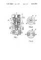
- FIGS. 1-3there is shown therein an actuating means in the form of a solenoid valve which is generally designated by the numeral 10.
- the valveincludes the usual solenoid coil 11, which is disposed around a solenoid core tube 12.
- the tubehas a spring 13, which is in biased relation between the tube 12 and a solenoid plunger 15.
- the plunger 15reciprocates in the core tube 12 carrying with it an extension or piston 16.
- At the lower end of the pistonis a valve member 17.
- the constructionis such that the valve member moves toward and away from a valve seat 18.
- the seatis located within the valve body 19 and between inlet passage 20 and outlet passage 21.
- the space above the inlet passage 20 which surrounds the valve member 17 and communicates with the outlet passage 21,is sealed by a diaphragm 22.
- the diaphragmperipherally engages the body 19 at its outer circumference and also engages the extension 16 at its inner circumference.
- the diaphragm 22is utilized to prevent any passage of said liquid to the solenoid, to attempt to prevent damage thereto.
- such diaphragmshave heretofore been known to become worn rather frequently, whereby their function is rendered useless and damage has been done to the expensive solenoid without detection of any leakage, whereupon the solenoid must be replaced.
- the present inventionprovides means whereby damage to the solenoid can be prevented as soon as diaphragm 22 begins to wear.
- the meansare such that the wear of the diaphragm 22 can be detected before any damage to the solenoid itself.
- these meanscomprise a second sealing diaphragm 23 which is secured between and peripherally engages the valve body 19.
- the inner circumference of the diaphragm 23engages the extension 16.
- a second leakproof areais provided.
- the diaphragm 23is disposed in a spaced relation in an axial direction to diaphragm 22. Also located between the diaphragms 23 and 22 is a spacer 24.
- a passage 25is provided from the interior of the spacer 24 through the valve body 19.
- the passage 25may be connected to any means for transporting the liquid leaking through the passage to a remote location.
- the inventionprovides an easy and simple manner for detecting leakage of the diaphragm 22 of a solenoid valve 10 so that it can be replaced before any leakage beyond the extension 16 of the solenoid plunger occurs.
- FIGS. 4 and 5show a valve in which the inlet passage 20a and outlet passage 21a are located correspondingly above and below the valve seat 18a. This form is particularly beneficial when high flow rates and high pressures are encountered. In view of the fact that the fluid passes through the inlet above the valve seat 18a the pressure rating is difficult to obtain with a large flat diaphragm and another arrangement as hereinafter described is disclosed.
- a solenoid 10awhich has the conventional solenoid coil (not shown) is disposed around solenoid core tube 12a.
- a plunger 15areciprocates in the core tube 12a carrying with it an extension or piston 16a.
- the plungeris preferably made of plastic such as Teflon.
- a set of seals 30, 31 and 32are provided through which the plunger 15a passes in order to minimize the area which is affected by the pressure of the flow of liquids through the inlet passage 20a to the outlet passage 21a.
- the seals 30-32are disposed above the inlet passage 20a and the valve seat 18a.
- a passage 25ais provided below the solenoid 10a.
- the passagewill carry any liquid passing through the sealed area and the fact that the seals 30-32 are damaged can be readily detectable by visual inspection.
- the escaping fluidcannot cause damage to the solenoid or system by reason of the provision of a seal or diaphragm 23a which prevents the passage of the fluid into the solenoid chamber.
- the diaphragm 23abecause of the arrangement, i.e. the substantially continuous slidable relation between the plunger 15a and the axial bore in the valve which surrounds it above and below passage 25a, is never in contact with any fluid under pressure.
- this modified form of the present inventionprevents any damage to the actuator even with high flow rates and high pressure in the valve.
- FIGS. 6 and 7the damage detecting means of the present invention are shown in an air driven metering valve.
- valve 40is provided with an inlet port 41 and an outlet port 42 for the flow of liquids passing through chamber 43.
- Airis introduced into air chamber 44 through passages 45 and 46 which act as both the inlet and outlet ports under the conditions hereinafter described.
- the passages 45 and 46are located in passage containing valve members 47 and 48 respectively.
- Reciprocating pistons 49 and 50are connected to each other by shaft or plunger 51 and are slidably mounted in the valve housing.
- Seals 52 and 53surround the piston 49 normally preventing the liquid in chamber 43 from flowing into the actuating chamber 44.
- a plurality of seals 54, 55 and 56surround the shaft or plunger 51 located in valve member 47.
- a detecting passage 57is located, as shown, in valve member 47.
- a measured, predetermined amount of liquidflows into chamber 43 through inlet 41.
- the pistons 49 and 50are located adjacent their respective valve members 47 and 48 during this time, that is in the liquid filling position shown in FIG. 6.
- air under pressureis introduced into chamber 44 through inlet 46. This action moves the piston 50 and its interconnected piston 49 in such fashion as to force the liquid out of chamber 43 through outlet 42 to its ultimate destination.
- air in the chamber 44passes outwardly through passage 45.
- chamber 44serves as a double acting cylinder and piston 50 correspondingly serves as a double acting piston for actuating piston 49.
- any liquid bypassing these sealswill flow to and through passage 57 to the exterior of the valve housing.
- there is a visual indication of fluid leakagebecause of damage to the seals.
- the fluidcannot pass into the actuating chamber 44 because of the presence of the seals 54-56.
- the seals 52 and 53can be replaced before the liquid flows into the chamber 44 preserving the integrity of the air chamber.
Landscapes
- Engineering & Computer Science (AREA)
- General Engineering & Computer Science (AREA)
- Mechanical Engineering (AREA)
- Magnetically Actuated Valves (AREA)
Abstract
Description
This is a continuation of copending parent application Ser. No. 309,903, filed Nov. 27, 1972, and now abandoned.
This invention relates in general to the construction of valves and, in particular, to a new and useful device for detecting leakage past a diaphragm or seal of a solenoid, air driven or other type valve in order to prevent damage to the actuating means.
Prior to the present invention, it was known to provide a valve with a diaphragm which seals in order to prevent any liquid from entering into the actuating area and into the electrical coil for energizing the solenoid. The disadvantage of the construction of such valves is that when the diaphragm begins to wear and leakage develops, such leakage is not detected before damage has been done to the actuator itself. As a consequence, costly replacement of the solenoid was necessary. Also, system failure could occur in addition to valve failure.
In accordance with the present invention, the valve includes two diaphragms or seals which are located at spaced axial locations in order to seal a space which is connected to the atmosphere through a leak detection passage. With the construction, any leakage past the first diaphragm or seal will move outwardly through the detection passage and be readily visible. This provides a direct indication that the first diaphragm is leaking and that it needs to be replaced. The replacement of the diaphragm is easy and simple and thus considerable damage to the valve and system is avoided.
Accordingly, it is an object of the invention to provide a sealed valve construction which includes a seal space in proximity to the sealing means which is communicated to the exterior so that any leakage past the sealing means is immediately detectable and correctable.
A further object of the invention is to provide a valve construction with leakage detection means and which is simple in design, rugged in construction, and economical to manufacture.
The various features of novelty which characterize the invention are pointed out with particularity in the claims annexed to and forming a part of this disclosure. For a better understanding of the invention, its operating advantages and specific objects attained by its uses, reference should be had to the accompanying drawing and descriptive matter in which there is illustrated a preferred embodiment of the invention.
In the Drawing:
FIG. 1 is a vertical sectional view of a solenoid valve constructed in accordance with the invention;
FIG 2 is a section taken along theline 2--2 of FIG. 1; and
FIG. 3 is a section taken along theline 3--3 of FIG. 1.
FIG. 4 is a vertical sectional view of a modified form of a solenoid valve constructed in accordance with the invention.
FIG. 5 is a section taken along the line 5--5 of FIG. 4.
FIG. 6 is a vertical sectional view of still another form of valve, namely, an air pressuring metering valve constructed in accordance with the invention.
FIG. 7 is a section taken along thelines 7--7 of FIG. 6.
Referring to the drawings in the form shown in FIGS. 1-3, there is shown therein an actuating means in the form of a solenoid valve which is generally designated by thenumeral 10. The valve includes the usual solenoid coil 11, which is disposed around asolenoid core tube 12. The tube has aspring 13, which is in biased relation between thetube 12 and a solenoid plunger 15. The plunger 15 reciprocates in thecore tube 12 carrying with it an extension orpiston 16. At the lower end of the piston is a valve member 17. The construction is such that the valve member moves toward and away from a valve seat 18. The seat is located within thevalve body 19 and betweeninlet passage 20 andoutlet passage 21. The space above theinlet passage 20 which surrounds the valve member 17 and communicates with theoutlet passage 21, is sealed by adiaphragm 22. The diaphragm peripherally engages thebody 19 at its outer circumference and also engages theextension 16 at its inner circumference. Thus, the flow of liquid between theinlet passage 20 andoutlet passage 21 is insured at the appropriate times. Thediaphragm 22 is utilized to prevent any passage of said liquid to the solenoid, to attempt to prevent damage thereto. However, such diaphragms have heretofore been known to become worn rather frequently, whereby their function is rendered useless and damage has been done to the expensive solenoid without detection of any leakage, whereupon the solenoid must be replaced.
The present invention provides means whereby damage to the solenoid can be prevented as soon asdiaphragm 22 begins to wear. The means are such that the wear of thediaphragm 22 can be detected before any damage to the solenoid itself. In the form shown, these means comprise asecond sealing diaphragm 23 which is secured between and peripherally engages thevalve body 19. The inner circumference of thediaphragm 23 engages theextension 16. As a consequence, a second leakproof area is provided. Thediaphragm 23 is disposed in a spaced relation in an axial direction todiaphragm 22. Also located between thediaphragms spacer 24. In accordance with the invention apassage 25 is provided from the interior of thespacer 24 through thevalve body 19. As a consequence, it will be noted that if thediaphragm 22 is in any way damaged through wear or otherwise, the liquid flowing frominlet 20 will bypass thisdiaphragm 22. However, such liquid flow will not damage thesolenoid 10 in any way, as flow to the solenoid will be prevented bydiaphragm 23. In the meantime, damage to thediaphragm 22 can be detected by the flow of such liquid out through the port orpassage 25, which will flow to the exterior of thebody 19. Thus, immediate detection of damage to thediaphragm 22 is possible by visual inspection. When the flow is visible at the exterior of thepassage 25, it is a sign that thefirst diaphragm 22 needs replacement and this can be easily and quickly done before any major damage is done to the solenoid by a flow of liquid upwardly into the solenoid core tube 11.
Thepassage 25 may be connected to any means for transporting the liquid leaking through the passage to a remote location.
Thus, the invention provides an easy and simple manner for detecting leakage of thediaphragm 22 of asolenoid valve 10 so that it can be replaced before any leakage beyond theextension 16 of the solenoid plunger occurs.
FIGS. 4 and 5 show a valve in which theinlet passage 20a andoutlet passage 21a are located correspondingly above and below thevalve seat 18a. This form is particularly beneficial when high flow rates and high pressures are encountered. In view of the fact that the fluid passes through the inlet above thevalve seat 18a the pressure rating is difficult to obtain with a large flat diaphragm and another arrangement as hereinafter described is disclosed.
In this construction asolenoid 10a which has the conventional solenoid coil (not shown) is disposed aroundsolenoid core tube 12a. Aplunger 15a reciprocates in thecore tube 12a carrying with it an extension orpiston 16a. The plunger is preferably made of plastic such as Teflon. A set ofseals 30, 31 and 32 are provided through which theplunger 15a passes in order to minimize the area which is affected by the pressure of the flow of liquids through theinlet passage 20a to theoutlet passage 21a. The seals 30-32 are disposed above theinlet passage 20a and thevalve seat 18a.
In the event the seals become damaged or worn apassage 25a is provided below thesolenoid 10a. The passage will carry any liquid passing through the sealed area and the fact that the seals 30-32 are damaged can be readily detectable by visual inspection. According to the present invention, the escaping fluid cannot cause damage to the solenoid or system by reason of the provision of a seal ordiaphragm 23a which prevents the passage of the fluid into the solenoid chamber. It is to be noted that despite the pressure in the system, thediaphragm 23a, because of the arrangement, i.e. the substantially continuous slidable relation between theplunger 15a and the axial bore in the valve which surrounds it above and belowpassage 25a, is never in contact with any fluid under pressure.
Thus, it may be seen that this modified form of the present invention prevents any damage to the actuator even with high flow rates and high pressure in the valve.
In the form shown in FIGS. 6 and 7 the damage detecting means of the present invention are shown in an air driven metering valve.
As shown thevalve 40 is provided with an inlet port 41 and an outlet port 42 for the flow of liquids passing throughchamber 43. Air is introduced intoair chamber 44 throughpassages passages valve members pistons plunger 51 and are slidably mounted in the valve housing.
In operation of the valve, a measured, predetermined amount of liquid flows intochamber 43 through inlet 41. Thepistons respective valve members chamber 43 is filled with the desired amount of liquid, air under pressure is introduced intochamber 44 throughinlet 46. This action moves thepiston 50 and itsinterconnected piston 49 in such fashion as to force the liquid out ofchamber 43 through outlet 42 to its ultimate destination. During this part of the operation air in thechamber 44 passes outwardly throughpassage 45.
Thereafter, air under pressure is introduced through passage 45 (which becomes the inlet port) moving thepistons chamber 43 through inlet 41. In this part of the operation air in thechamber 44 passes outwardly throughpassage 46. The above cycle is then sequentially repeated. Thus,chamber 44 serves as a double acting cylinder andpiston 50 correspondingly serves as a double acting piston for actuatingpiston 49.
According to the present invention, in the event of damage or wear to theseals passage 57 to the exterior of the valve housing. As a consequence, there is a visual indication of fluid leakage because of damage to the seals. However, the fluid cannot pass into theactuating chamber 44 because of the presence of the seals 54-56. Thus, theseals chamber 44 preserving the integrity of the air chamber.
While the invention has been described in detail with reference to specific forms, it will be understood that such description is in no way intended to limit the scope of the invention as set forth in the appended claims.
Claims (3)
1. Valve construction comprising:
actuating means,
a valve body having a fluid inlet passage and a fluid outlet passage, a valve seat between said inlet and outlet passages and a cavity above the valve seat,
a valve flow control plunger operatively arranged between the actuating means and the valve seat and extending through the cavity in the valve body and responsive to the actuating means for movement relative to the valve seat for correspondingly controlling fluid flow through the valve seat from the inlet passage to the outlet passage,
spaced apart first and second diaphragms correspondingly secured between the plunger and the valve body for sealing against fluid flow to the actuating means, the second diaphragm sealing against fluid flow along the plunger beyond the first diaphragm,
a leak detection passage extending from the interior of the valve body outwardly to the exterior thereof and located between the first and second diaphragms for the flow of any fluid leaking past the first diaphragm to a visible location outside of the valve body, and
a spacer in the cavity surrounding the plunger and located between the first and second diaphragms and having an opening therethrough defining a portion of the detection passage.
2. Valve construction according to claim 1 wherein spring means are provided for normally biasing the plunger toward operative sealing engagement with the valve seat, and the actuating means include a solenoid having a coil operatively surrounding the plunger for moving the plunger away from the valve seat against the biasing action of the spring means.
3. Valve construction comprising:
actuating means including a solenoid having an axially extending coil,
a valve body having a fluid inlet passage and a fluid outlet passage, a valve seat between said inlet and outlet passages and a cavity axially extending above the valve seat,
a valve control plunger operatively arranged between the actuating means and the valve seat and axially extending through the cavity in the valve body, the plunger being normally resiliently biased toward operative sealing engagement with the valve seat and the coil of the solenoid operatively surrounding the plunger for moving the plunger away from the valve seat against such normal resilient bias whereby the plunger is responsive to the actuating means for movement relative to the valve seat for correspondingly controlling fluid flow through the valve seat from the inlet passage to the outlet passage,
axially spaced apart first and second diaphragms correspondingly secured between the plunger and the valve body for sealing against fluid flow to the actuating means, the second diaphragm sealing against fluid flow along the plunger axially beyond the first diaphragm in the direction of the actuating means,
a leak detection passage extending substantially crosswise of the axial direction of the plunger from the interior of the valve body outwardly to the exterior thereof and located axially between the first and second diaphragms for the flow of any fluid leaking past the first diahragm to a visible location outside of the valve body, and
an axially extending spacer in the cavity surrounding the plunger and located axially between the first and second diaphragms and having an opening extending substantially crosswise of the axial direction therethrough and defining a portion of the detection passage.
Priority Applications (1)
| Application Number | Priority Date | Filing Date | Title |
|---|---|---|---|
| US05/526,991US4010769A (en) | 1972-11-27 | 1974-11-25 | Leak detection arrangement for valve having sealing means |
Applications Claiming Priority (2)
| Application Number | Priority Date | Filing Date | Title |
|---|---|---|---|
| US30990372A | 1972-11-27 | 1972-11-27 | |
| US05/526,991US4010769A (en) | 1972-11-27 | 1974-11-25 | Leak detection arrangement for valve having sealing means |
Related Parent Applications (1)
| Application Number | Title | Priority Date | Filing Date |
|---|---|---|---|
| US30990372AContinuation | 1972-11-27 | 1972-11-27 |
Publications (1)
| Publication Number | Publication Date |
|---|---|
| US4010769Atrue US4010769A (en) | 1977-03-08 |
Family
ID=26977091
Family Applications (1)
| Application Number | Title | Priority Date | Filing Date |
|---|---|---|---|
| US05/526,991Expired - LifetimeUS4010769A (en) | 1972-11-27 | 1974-11-25 | Leak detection arrangement for valve having sealing means |
Country Status (1)
| Country | Link |
|---|---|
| US (1) | US4010769A (en) |
Cited By (75)
| Publication number | Priority date | Publication date | Assignee | Title |
|---|---|---|---|---|
| US4171087A (en)* | 1977-11-03 | 1979-10-16 | Emerson Electric Co. | Control valve |
| US4304391A (en)* | 1975-12-24 | 1981-12-08 | Nissan Motor Company, Ltd. | Electromagnetically operated valve assembly |
| US4436108A (en) | 1980-10-20 | 1984-03-13 | Ellsworth Eugene W | Valve assembly |
| US4521757A (en)* | 1982-08-09 | 1985-06-04 | Eaton Corporation | High speed electromagnetic mechanical switch |
| US4543983A (en)* | 1978-12-22 | 1985-10-01 | Pauliukonis Richard S | O-ring solenoid water valves |
| US4574920A (en)* | 1984-08-02 | 1986-03-11 | Lubriquip - Houdaille, Inc. | Hydropneumatic monitoring device |
| US4790353A (en)* | 1982-08-09 | 1988-12-13 | Eaton Corporation | Electromagnetic hydraulic valve operator |
| US4840195A (en)* | 1987-11-19 | 1989-06-20 | Air Products And Chemicals, Inc. | Piston-backed gas pressure regulator |
| US4867201A (en)* | 1989-03-06 | 1989-09-19 | Harsco Corporation | Parallel-motion dual-diaphragm valve |
| US4901751A (en)* | 1989-06-15 | 1990-02-20 | Systems Chemistry, Inc. | Fluid control valve and system with leak detection and containment |
| US4972867A (en)* | 1989-11-03 | 1990-11-27 | Ruesch J O | Valve stem seal leak protection and detection apparatus |
| US5002086A (en)* | 1990-05-11 | 1991-03-26 | Fluoroware, Inc. | Plastic control valve |
| US5004011A (en)* | 1990-08-10 | 1991-04-02 | Fluoroware, Inc. | Position indicating control valve |
| US5009778A (en)* | 1989-02-27 | 1991-04-23 | Hewlett-Packard Company | Axially-driven valve controlled fluid trapping assembly |
| US5151178A (en)* | 1989-02-27 | 1992-09-29 | Hewlett-Packard Company | Axially-driven valve controlled trapping assembly |
| US5178767A (en)* | 1989-02-27 | 1993-01-12 | Hewlett-Packard Company | Axially-driven valve controlled trapping assembly |
| US5188337A (en)* | 1990-12-13 | 1993-02-23 | Carl Freudenberg | Control valve with pressure equalization |
| US5203370A (en)* | 1991-11-26 | 1993-04-20 | Block Gary C | Mounting apparatus with fugitive emission collection means for directly coupling a rotary valve to an actuator having rotary drive means |
| US5261442A (en)* | 1992-11-04 | 1993-11-16 | Bunnell Plastics, Inc. | Diaphragm valve with leak detection |
| US5263682A (en)* | 1992-03-17 | 1993-11-23 | Whitey Co. | Valve stem packing system |
| US5372352A (en)* | 1990-09-28 | 1994-12-13 | Johnston Pump/General Valve, Inc. | Apparatus for sealing a fluid carrying device |
| US5586576A (en)* | 1994-09-28 | 1996-12-24 | Tetra Laval Holdings & Finance S.A. | Dosing valve having seal failure detection |
| US5614089A (en)* | 1990-07-13 | 1997-03-25 | Isco, Inc. | Apparatus and method for supercritical fluid extraction or supercritical fluid chromatography |
| EP0892204A2 (en) | 1997-07-14 | 1999-01-20 | Furon Company | Improved diaphragm valve with leak detection |
| US6361020B1 (en)* | 1999-05-06 | 2002-03-26 | The Boc Group Plc | Valve for use with high purity gas |
| US6550338B1 (en) | 2000-07-07 | 2003-04-22 | Ardishir Rashidi | Pressure sensing device |
| US6578435B2 (en) | 1999-11-23 | 2003-06-17 | Nt International, Inc. | Chemically inert flow control with non-contaminating body |
| US6595240B2 (en) | 1998-12-18 | 2003-07-22 | Entegris, Inc. | Creep resistant valve |
| US6609698B1 (en) | 2000-10-25 | 2003-08-26 | Arichell Technologies, Inc. | Ferromagnetic/fluid valve actuator |
| USRE38300E1 (en) | 1995-10-03 | 2003-11-11 | Nt International, Inc. | Non-fluid conducting pressure module having non-contaminating body and isolation member |
| US20040046137A1 (en)* | 2000-02-29 | 2004-03-11 | Arichell Technologies, Inc. | Apparatus and method for controlling fluid flow |
| US6740827B1 (en)* | 2002-11-27 | 2004-05-25 | Target Rock Division Of Curtis-Wright Flow Control Corporation | Bi-directional piloted solenoid-operated valve |
| US6752371B2 (en) | 2002-06-19 | 2004-06-22 | Arichell Technologies, Inc. | Valve actuator having small isolated plunger |
| USRE38557E1 (en) | 1995-10-03 | 2004-07-20 | Nt International, Inc. | Non-contaminating pressure transducer module |
| US20040141296A1 (en)* | 1998-09-15 | 2004-07-22 | Coico Patrick Anthony | Stress resistant land grid array (LGA) module and method of forming the same |
| US20040164261A1 (en)* | 2003-02-20 | 2004-08-26 | Parsons Natan E. | Automatic bathroom flushers with modular design |
| US20040221899A1 (en)* | 2001-12-04 | 2004-11-11 | Parsons Natan E. | Electronic faucets for long-term operation |
| US20040232370A1 (en)* | 2001-12-26 | 2004-11-25 | Parsons Natan E. | Bathroom flushers with novel sensors and controllers |
| US20050006617A1 (en)* | 2003-07-11 | 2005-01-13 | Leys John A. | Extended stroke valve and diaphragm |
| US20050062004A1 (en)* | 2001-12-04 | 2005-03-24 | Parsons Natan E. | Automatic bathroom flushers |
| EP1258670A3 (en)* | 2001-05-09 | 2005-06-15 | The BOC Group plc | Gas containment system |
| US20050199842A1 (en)* | 2002-06-24 | 2005-09-15 | Parsons Natan E. | Automated water delivery systems with feedback control |
| US20050258390A1 (en)* | 2004-05-18 | 2005-11-24 | Johnson Controls Technology Company | Valve system |
| US20060006354A1 (en)* | 2002-12-04 | 2006-01-12 | Fatih Guler | Optical sensors and algorithms for controlling automatic bathroom flushers and faucets |
| US20060276575A1 (en)* | 2005-06-02 | 2006-12-07 | Kao Corporation | Plasticizer for biodegradable resin |
| US20080006328A1 (en)* | 2006-07-06 | 2008-01-10 | Honeywell International, Inc. | Electric motor pressure relief plate |
| US20080161697A1 (en)* | 1992-06-17 | 2008-07-03 | Britton Chance | Examination of subjects using photon migration with high directionality techniques |
| US7396000B2 (en) | 2001-12-04 | 2008-07-08 | Arichell Technologies Inc | Passive sensors for automatic faucets and bathroom flushers |
| US20090026220A1 (en)* | 2007-07-25 | 2009-01-29 | Reynold Ramnarine | Double-action fluid weighing and dispensing process and system |
| US20090049599A1 (en)* | 2002-12-04 | 2009-02-26 | Parsons Natan E | Passive sensors for automatic faucets and bathroom flushers |
| USD598975S1 (en) | 2004-02-20 | 2009-08-25 | Sloan Valve Company | Enclosure for automatic bathroom flusher |
| USD598978S1 (en) | 2004-02-20 | 2009-08-25 | Sloan Valve Company | Enclosure for automatic bathroom flusher |
| USD598976S1 (en) | 2004-02-20 | 2009-08-25 | Sloan Valve Company | Enclosure for automatic bathroom flusher |
| USD598977S1 (en) | 2004-02-20 | 2009-08-25 | Sloan Valve Company | Enclosure for automatic bathroom flusher |
| USD598974S1 (en) | 2004-02-20 | 2009-08-25 | Sloan Valve Company | Automatic bathroom flusher cover |
| USD599435S1 (en) | 2004-02-20 | 2009-09-01 | Sloan Valve Company | Enclosure for automatic bathroom flusher |
| USD599436S1 (en) | 2004-02-20 | 2009-09-01 | Sloan Valve Company | Enclosure for automatic bathroom flusher |
| USD599886S1 (en) | 2004-02-20 | 2009-09-08 | Sloan Valve Company | Enclosure for automatic bathroom flusher |
| USD599885S1 (en) | 2004-02-20 | 2009-09-08 | Sloan Valve Company | Enclosure for automatic bathroom flusher |
| USD600318S1 (en) | 2004-02-20 | 2009-09-15 | Sloan Valve Company | Enclosure for automatic bathroom flusher |
| USD600782S1 (en) | 2004-02-20 | 2009-09-22 | Sloan Valve Company | Enclosure for automatic bathroom flusher |
| USD600781S1 (en) | 2004-02-20 | 2009-09-22 | Sloan Valve Company | Enclosure for automatic bathroom flusher |
| USD601224S1 (en) | 2004-02-20 | 2009-09-29 | Sloan Valve Company | Enclosure for automatic bathroom flusher |
| USD602561S1 (en) | 2004-02-20 | 2009-10-20 | Sloan Valve Company | Enclosure for automatic bathroom flusher |
| US20100051841A1 (en)* | 2000-02-29 | 2010-03-04 | Kay Herbert | Electromagnetic apparatus and method for controlling fluid flow |
| USD620554S1 (en) | 2004-02-20 | 2010-07-27 | Sloan Valve Company | Enclosure for automatic bathroom flusher |
| USD621909S1 (en) | 2004-02-20 | 2010-08-17 | Sloan Valve Company | Enclosure for automatic bathroom flusher |
| USD623268S1 (en) | 2004-02-20 | 2010-09-07 | Sloan Valve Company | Enclosure for automatic bathroom flusher |
| US20100252759A1 (en)* | 2003-02-20 | 2010-10-07 | Fatih Guler | Automatic bathroom flushers |
| USD629069S1 (en) | 2004-02-20 | 2010-12-14 | Sloan Valve Company | Enclosure for automatic bathroom flusher |
| US20110017929A1 (en)* | 2003-02-20 | 2011-01-27 | Fatih Guler | Low volume automatic bathroom flushers |
| US7921480B2 (en) | 2001-11-20 | 2011-04-12 | Parsons Natan E | Passive sensors and control algorithms for faucets and bathroom flushers |
| USRE42401E1 (en) | 2000-04-24 | 2011-05-31 | Entegris, Inc. | Double diaphragm precision throttling valve |
| US9695579B2 (en) | 2011-03-15 | 2017-07-04 | Sloan Valve Company | Automatic faucets |
| US10508423B2 (en) | 2011-03-15 | 2019-12-17 | Sloan Valve Company | Automatic faucets |
Citations (7)
| Publication number | Priority date | Publication date | Assignee | Title |
|---|---|---|---|---|
| US1042745A (en)* | 1911-12-28 | 1912-10-29 | Edward Zahm | Pressure-regulator. |
| US2031478A (en)* | 1932-10-07 | 1936-02-18 | Gen Electric | Fluid control means |
| US2382235A (en)* | 1943-08-12 | 1945-08-14 | Harry H Lamar | Valve structure |
| US2770799A (en)* | 1953-07-24 | 1956-11-13 | Charles H Horn | Emergency diaphragm for air brakes and the like |
| US2934090A (en)* | 1955-11-25 | 1960-04-26 | Marotta Valve Corp | Three-way magnetic valve |
| GB941421A (en)* | 1959-06-29 | 1963-11-13 | Apv Co Ltd | Improvements in fluid-flow control valves |
| US3307574A (en)* | 1964-02-07 | 1967-03-07 | Acf Ind Inc | Drain structure for venting leaked fluid from valve stem packing |
- 1974
- 1974-11-25USUS05/526,991patent/US4010769A/ennot_activeExpired - Lifetime
Patent Citations (7)
| Publication number | Priority date | Publication date | Assignee | Title |
|---|---|---|---|---|
| US1042745A (en)* | 1911-12-28 | 1912-10-29 | Edward Zahm | Pressure-regulator. |
| US2031478A (en)* | 1932-10-07 | 1936-02-18 | Gen Electric | Fluid control means |
| US2382235A (en)* | 1943-08-12 | 1945-08-14 | Harry H Lamar | Valve structure |
| US2770799A (en)* | 1953-07-24 | 1956-11-13 | Charles H Horn | Emergency diaphragm for air brakes and the like |
| US2934090A (en)* | 1955-11-25 | 1960-04-26 | Marotta Valve Corp | Three-way magnetic valve |
| GB941421A (en)* | 1959-06-29 | 1963-11-13 | Apv Co Ltd | Improvements in fluid-flow control valves |
| US3307574A (en)* | 1964-02-07 | 1967-03-07 | Acf Ind Inc | Drain structure for venting leaked fluid from valve stem packing |
Cited By (116)
| Publication number | Priority date | Publication date | Assignee | Title |
|---|---|---|---|---|
| US4304391A (en)* | 1975-12-24 | 1981-12-08 | Nissan Motor Company, Ltd. | Electromagnetically operated valve assembly |
| US4171087A (en)* | 1977-11-03 | 1979-10-16 | Emerson Electric Co. | Control valve |
| US4543983A (en)* | 1978-12-22 | 1985-10-01 | Pauliukonis Richard S | O-ring solenoid water valves |
| US4436108A (en) | 1980-10-20 | 1984-03-13 | Ellsworth Eugene W | Valve assembly |
| US4521757A (en)* | 1982-08-09 | 1985-06-04 | Eaton Corporation | High speed electromagnetic mechanical switch |
| US4790353A (en)* | 1982-08-09 | 1988-12-13 | Eaton Corporation | Electromagnetic hydraulic valve operator |
| US4574920A (en)* | 1984-08-02 | 1986-03-11 | Lubriquip - Houdaille, Inc. | Hydropneumatic monitoring device |
| US4840195A (en)* | 1987-11-19 | 1989-06-20 | Air Products And Chemicals, Inc. | Piston-backed gas pressure regulator |
| US5178767A (en)* | 1989-02-27 | 1993-01-12 | Hewlett-Packard Company | Axially-driven valve controlled trapping assembly |
| US5151178A (en)* | 1989-02-27 | 1992-09-29 | Hewlett-Packard Company | Axially-driven valve controlled trapping assembly |
| US5009778A (en)* | 1989-02-27 | 1991-04-23 | Hewlett-Packard Company | Axially-driven valve controlled fluid trapping assembly |
| US4867201A (en)* | 1989-03-06 | 1989-09-19 | Harsco Corporation | Parallel-motion dual-diaphragm valve |
| WO1990015977A1 (en)* | 1989-06-15 | 1990-12-27 | Systems Chemistry, Inc. | Fluid control valve and system with leak detection and containment |
| US4901751A (en)* | 1989-06-15 | 1990-02-20 | Systems Chemistry, Inc. | Fluid control valve and system with leak detection and containment |
| US4972867A (en)* | 1989-11-03 | 1990-11-27 | Ruesch J O | Valve stem seal leak protection and detection apparatus |
| USRE34923E (en)* | 1989-11-03 | 1995-05-02 | Neotecha Ag | Valve stem seal leak protection and detection apparatus |
| US5002086A (en)* | 1990-05-11 | 1991-03-26 | Fluoroware, Inc. | Plastic control valve |
| US5750027A (en)* | 1990-07-13 | 1998-05-12 | Isco, Inc. | Apparatus and method for supercritical fluid extraction or supercritical fluid chromatography |
| US5614089A (en)* | 1990-07-13 | 1997-03-25 | Isco, Inc. | Apparatus and method for supercritical fluid extraction or supercritical fluid chromatography |
| US5004011A (en)* | 1990-08-10 | 1991-04-02 | Fluoroware, Inc. | Position indicating control valve |
| US5372352A (en)* | 1990-09-28 | 1994-12-13 | Johnston Pump/General Valve, Inc. | Apparatus for sealing a fluid carrying device |
| US5188337A (en)* | 1990-12-13 | 1993-02-23 | Carl Freudenberg | Control valve with pressure equalization |
| US5203370A (en)* | 1991-11-26 | 1993-04-20 | Block Gary C | Mounting apparatus with fugitive emission collection means for directly coupling a rotary valve to an actuator having rotary drive means |
| US5263682A (en)* | 1992-03-17 | 1993-11-23 | Whitey Co. | Valve stem packing system |
| US20080161697A1 (en)* | 1992-06-17 | 2008-07-03 | Britton Chance | Examination of subjects using photon migration with high directionality techniques |
| US5261442A (en)* | 1992-11-04 | 1993-11-16 | Bunnell Plastics, Inc. | Diaphragm valve with leak detection |
| US5586576A (en)* | 1994-09-28 | 1996-12-24 | Tetra Laval Holdings & Finance S.A. | Dosing valve having seal failure detection |
| USRE38557E1 (en) | 1995-10-03 | 2004-07-20 | Nt International, Inc. | Non-contaminating pressure transducer module |
| USRE38300E1 (en) | 1995-10-03 | 2003-11-11 | Nt International, Inc. | Non-fluid conducting pressure module having non-contaminating body and isolation member |
| EP0892204A2 (en) | 1997-07-14 | 1999-01-20 | Furon Company | Improved diaphragm valve with leak detection |
| US5967173A (en)* | 1997-07-14 | 1999-10-19 | Furon Corporation | Diaphragm valve with leak detection |
| US20040141296A1 (en)* | 1998-09-15 | 2004-07-22 | Coico Patrick Anthony | Stress resistant land grid array (LGA) module and method of forming the same |
| US6595240B2 (en) | 1998-12-18 | 2003-07-22 | Entegris, Inc. | Creep resistant valve |
| US6361020B1 (en)* | 1999-05-06 | 2002-03-26 | The Boc Group Plc | Valve for use with high purity gas |
| US6578435B2 (en) | 1999-11-23 | 2003-06-17 | Nt International, Inc. | Chemically inert flow control with non-contaminating body |
| US20040046137A1 (en)* | 2000-02-29 | 2004-03-11 | Arichell Technologies, Inc. | Apparatus and method for controlling fluid flow |
| US20100051841A1 (en)* | 2000-02-29 | 2010-03-04 | Kay Herbert | Electromagnetic apparatus and method for controlling fluid flow |
| US8576032B2 (en) | 2000-02-29 | 2013-11-05 | Sloan Valve Company | Electromagnetic apparatus and method for controlling fluid flow |
| US20060108552A1 (en)* | 2000-02-29 | 2006-05-25 | Arichell Technologies, Inc. | Apparatus and method for controlling fluid flow |
| US9435460B2 (en) | 2000-02-29 | 2016-09-06 | Sloan Value Company | Electromagnetic apparatus and method for controlling fluid flow |
| US8505573B2 (en) | 2000-02-29 | 2013-08-13 | Sloan Valve Company | Apparatus and method for controlling fluid flow |
| US6948697B2 (en) | 2000-02-29 | 2005-09-27 | Arichell Technologies, Inc. | Apparatus and method for controlling fluid flow |
| USRE42401E1 (en) | 2000-04-24 | 2011-05-31 | Entegris, Inc. | Double diaphragm precision throttling valve |
| US6550338B1 (en) | 2000-07-07 | 2003-04-22 | Ardishir Rashidi | Pressure sensing device |
| US6609698B1 (en) | 2000-10-25 | 2003-08-26 | Arichell Technologies, Inc. | Ferromagnetic/fluid valve actuator |
| US6932316B2 (en) | 2000-10-25 | 2005-08-23 | Arichell Technologies, Inc. | Ferromagnetic/fluid valve actuator |
| US20060000995A1 (en)* | 2000-10-25 | 2006-01-05 | Arichell Technologies | Ferromagnetic/fluid valve actuator |
| EP1258670A3 (en)* | 2001-05-09 | 2005-06-15 | The BOC Group plc | Gas containment system |
| US7921480B2 (en) | 2001-11-20 | 2011-04-12 | Parsons Natan E | Passive sensors and control algorithms for faucets and bathroom flushers |
| US9822514B2 (en) | 2001-11-20 | 2017-11-21 | Sloan Valve Company | Passive sensors and control algorithms for faucets and bathroom flushers |
| US7690623B2 (en) | 2001-12-04 | 2010-04-06 | Arichell Technologies Inc. | Electronic faucets for long-term operation |
| US7396000B2 (en) | 2001-12-04 | 2008-07-08 | Arichell Technologies Inc | Passive sensors for automatic faucets and bathroom flushers |
| US8496025B2 (en) | 2001-12-04 | 2013-07-30 | Sloan Valve Company | Electronic faucets for long-term operation |
| US20050062004A1 (en)* | 2001-12-04 | 2005-03-24 | Parsons Natan E. | Automatic bathroom flushers |
| US20040221899A1 (en)* | 2001-12-04 | 2004-11-11 | Parsons Natan E. | Electronic faucets for long-term operation |
| US7069941B2 (en) | 2001-12-04 | 2006-07-04 | Arichell Technologies Inc. | Electronic faucets for long-term operation |
| US20100269923A1 (en)* | 2001-12-04 | 2010-10-28 | Parsons Natan E | Electronic faucets for long-term operation |
| US7437778B2 (en) | 2001-12-04 | 2008-10-21 | Arichell Technologies Inc. | Automatic bathroom flushers |
| US20070063158A1 (en)* | 2001-12-04 | 2007-03-22 | Parsons Natan E | Electronic faucets for long-term operation |
| US8042202B2 (en) | 2001-12-26 | 2011-10-25 | Parsons Natan E | Bathroom flushers with novel sensors and controllers |
| US20040232370A1 (en)* | 2001-12-26 | 2004-11-25 | Parsons Natan E. | Bathroom flushers with novel sensors and controllers |
| US7156363B2 (en) | 2001-12-26 | 2007-01-02 | Arichell Technologies, Inc. | Bathroom flushers with novel sensors and controllers |
| US20040201442A1 (en)* | 2002-06-19 | 2004-10-14 | Arichell Technologies, Inc. | Valve actuator having small isolated plunger |
| US6752371B2 (en) | 2002-06-19 | 2004-06-22 | Arichell Technologies, Inc. | Valve actuator having small isolated plunger |
| US20050199842A1 (en)* | 2002-06-24 | 2005-09-15 | Parsons Natan E. | Automated water delivery systems with feedback control |
| US7383721B2 (en) | 2002-06-24 | 2008-06-10 | Arichell Technologies Inc. | Leak Detector |
| US9763393B2 (en) | 2002-06-24 | 2017-09-19 | Sloan Valve Company | Automated water delivery systems with feedback control |
| US20060202051A1 (en)* | 2002-06-24 | 2006-09-14 | Parsons Natan E | Communication system for multizone irrigation |
| US20090179165A1 (en)* | 2002-06-24 | 2009-07-16 | Parsons Natan E | Automated water delivery systems with feedback control |
| US20040099831A1 (en)* | 2002-11-27 | 2004-05-27 | Target Rock Division Of Curtiss-Wright Flow Control Corporation | Bi-directional piloted solenoid-operated valve |
| US6740827B1 (en)* | 2002-11-27 | 2004-05-25 | Target Rock Division Of Curtis-Wright Flow Control Corporation | Bi-directional piloted solenoid-operated valve |
| US8955822B2 (en) | 2002-12-04 | 2015-02-17 | Sloan Valve Company | Passive sensors for automatic faucets and bathroom flushers |
| US7731154B2 (en) | 2002-12-04 | 2010-06-08 | Parsons Natan E | Passive sensors for automatic faucets and bathroom flushers |
| US8276878B2 (en) | 2002-12-04 | 2012-10-02 | Parsons Natan E | Passive sensors for automatic faucets |
| US20060006354A1 (en)* | 2002-12-04 | 2006-01-12 | Fatih Guler | Optical sensors and algorithms for controlling automatic bathroom flushers and faucets |
| US20100327197A1 (en)* | 2002-12-04 | 2010-12-30 | Parsons Natan E | Passive sensors for automatic faucets and bathroom flushers |
| US20100275359A1 (en)* | 2002-12-04 | 2010-11-04 | Fatih Guler | Optical sensors and algorithms for controlling automatic bathroom flushers and faucets |
| US20090049599A1 (en)* | 2002-12-04 | 2009-02-26 | Parsons Natan E | Passive sensors for automatic faucets and bathroom flushers |
| US20040227117A1 (en)* | 2003-02-20 | 2004-11-18 | Marcichow Martin E. | Novel enclosures for automatic bathroom flushers |
| US8556228B2 (en) | 2003-02-20 | 2013-10-15 | Sloan Valve Company | Enclosures for automatic bathroom flushers |
| US9598847B2 (en) | 2003-02-20 | 2017-03-21 | Sloan Valve Company | Enclosures for automatic bathroom flushers |
| US7188822B2 (en) | 2003-02-20 | 2007-03-13 | Arichell Technologies, Inc. | Enclosures for automatic bathroom flushers |
| US9169626B2 (en) | 2003-02-20 | 2015-10-27 | Fatih Guler | Automatic bathroom flushers |
| US20040164261A1 (en)* | 2003-02-20 | 2004-08-26 | Parsons Natan E. | Automatic bathroom flushers with modular design |
| US20110017929A1 (en)* | 2003-02-20 | 2011-01-27 | Fatih Guler | Low volume automatic bathroom flushers |
| US20100252759A1 (en)* | 2003-02-20 | 2010-10-07 | Fatih Guler | Automatic bathroom flushers |
| US7325781B2 (en) | 2003-02-20 | 2008-02-05 | Arichell Technologies Inc. | Automatic bathroom flushers with modular design |
| USD612014S1 (en) | 2003-02-20 | 2010-03-16 | Sloan Valve Company | Automatic bathroom flusher cover |
| US7063304B2 (en) | 2003-07-11 | 2006-06-20 | Entegris, Inc. | Extended stroke valve and diaphragm |
| US20050006617A1 (en)* | 2003-07-11 | 2005-01-13 | Leys John A. | Extended stroke valve and diaphragm |
| USD598977S1 (en) | 2004-02-20 | 2009-08-25 | Sloan Valve Company | Enclosure for automatic bathroom flusher |
| USD600782S1 (en) | 2004-02-20 | 2009-09-22 | Sloan Valve Company | Enclosure for automatic bathroom flusher |
| USD623268S1 (en) | 2004-02-20 | 2010-09-07 | Sloan Valve Company | Enclosure for automatic bathroom flusher |
| USD602561S1 (en) | 2004-02-20 | 2009-10-20 | Sloan Valve Company | Enclosure for automatic bathroom flusher |
| USD599436S1 (en) | 2004-02-20 | 2009-09-01 | Sloan Valve Company | Enclosure for automatic bathroom flusher |
| USD599435S1 (en) | 2004-02-20 | 2009-09-01 | Sloan Valve Company | Enclosure for automatic bathroom flusher |
| USD629069S1 (en) | 2004-02-20 | 2010-12-14 | Sloan Valve Company | Enclosure for automatic bathroom flusher |
| USD598974S1 (en) | 2004-02-20 | 2009-08-25 | Sloan Valve Company | Automatic bathroom flusher cover |
| USD601224S1 (en) | 2004-02-20 | 2009-09-29 | Sloan Valve Company | Enclosure for automatic bathroom flusher |
| USD620554S1 (en) | 2004-02-20 | 2010-07-27 | Sloan Valve Company | Enclosure for automatic bathroom flusher |
| USD599437S1 (en) | 2004-02-20 | 2009-09-01 | Sloan Valve Company | Automatic bathroom flusher cover |
| USD598976S1 (en) | 2004-02-20 | 2009-08-25 | Sloan Valve Company | Enclosure for automatic bathroom flusher |
| USD621909S1 (en) | 2004-02-20 | 2010-08-17 | Sloan Valve Company | Enclosure for automatic bathroom flusher |
| USD599885S1 (en) | 2004-02-20 | 2009-09-08 | Sloan Valve Company | Enclosure for automatic bathroom flusher |
| USD600318S1 (en) | 2004-02-20 | 2009-09-15 | Sloan Valve Company | Enclosure for automatic bathroom flusher |
| USD600781S1 (en) | 2004-02-20 | 2009-09-22 | Sloan Valve Company | Enclosure for automatic bathroom flusher |
| USD599886S1 (en) | 2004-02-20 | 2009-09-08 | Sloan Valve Company | Enclosure for automatic bathroom flusher |
| USD598975S1 (en) | 2004-02-20 | 2009-08-25 | Sloan Valve Company | Enclosure for automatic bathroom flusher |
| USD598978S1 (en) | 2004-02-20 | 2009-08-25 | Sloan Valve Company | Enclosure for automatic bathroom flusher |
| US20050258390A1 (en)* | 2004-05-18 | 2005-11-24 | Johnson Controls Technology Company | Valve system |
| US20060276575A1 (en)* | 2005-06-02 | 2006-12-07 | Kao Corporation | Plasticizer for biodegradable resin |
| US20080006328A1 (en)* | 2006-07-06 | 2008-01-10 | Honeywell International, Inc. | Electric motor pressure relief plate |
| US20090026220A1 (en)* | 2007-07-25 | 2009-01-29 | Reynold Ramnarine | Double-action fluid weighing and dispensing process and system |
| US7963422B2 (en) | 2007-07-25 | 2011-06-21 | W. R. Grace & Co.-Conn. | Double-action fluid weighing and dispensing process and system |
| US9695579B2 (en) | 2011-03-15 | 2017-07-04 | Sloan Valve Company | Automatic faucets |
| US10508423B2 (en) | 2011-03-15 | 2019-12-17 | Sloan Valve Company | Automatic faucets |
Similar Documents
| Publication | Publication Date | Title |
|---|---|---|
| US4010769A (en) | Leak detection arrangement for valve having sealing means | |
| US3702624A (en) | Piston pump | |
| US5826613A (en) | Flow control valve | |
| US5474303A (en) | Actuator rod hermetic sealing apparatus employing concentric bellows and pressure compensating sealing liquid with liquid monitoring system | |
| US2868498A (en) | Shut-off cock with annular piston sealing means for the ball plug | |
| US2635620A (en) | Automatic air bleed valve | |
| US3835878A (en) | Shutoff valve with leak indicating means | |
| US3285285A (en) | Valve | |
| US4052997A (en) | Leak detection arrangement for valve having sealing means | |
| US3326511A (en) | Magnetic valve with diaphragm sealed armature cylinder | |
| US4413647A (en) | Leak detection arrangement for valve having sealing means | |
| US3182597A (en) | Proportioning pump | |
| US7111821B2 (en) | Control valve, in particular plug valve with sealing system | |
| US4209040A (en) | Seal means for high pressure control valves | |
| US2691388A (en) | Pressure regulating valve for pumps | |
| US3540741A (en) | Seal assembly for a hydraulically operated cylinder | |
| ES416870A1 (en) | Safety check valve for pressure fluid operated apparatus in particular presses | |
| US2479454A (en) | Fluid flow control apparatus | |
| US3329159A (en) | Pilot-operated slide valve with position indicator | |
| US2587182A (en) | Hydraulic motor cylinder with stroke limiting valve | |
| US4594057A (en) | Injector pump | |
| US2524129A (en) | Valve | |
| US3776267A (en) | Pressure transfer unit with bellows | |
| US3219059A (en) | Dispensing valve | |
| US3946563A (en) | Master cylinders for dual hydraulic braking systems |