US4008369A - Telephone interfaced subscription cable television system especially useful in hotels and motels - Google Patents
Telephone interfaced subscription cable television system especially useful in hotels and motelsDownload PDFInfo
- Publication number
- US4008369A US4008369AUS05/554,347US55434775AUS4008369AUS 4008369 AUS4008369 AUS 4008369AUS 55434775 AUS55434775 AUS 55434775AUS 4008369 AUS4008369 AUS 4008369A
- Authority
- US
- United States
- Prior art keywords
- subscriber
- signal
- signals
- output
- telephone
- Prior art date
- Legal status (The legal status is an assumption and is not a legal conclusion. Google has not performed a legal analysis and makes no representation as to the accuracy of the status listed.)
- Expired - Lifetime
Links
- 238000012795verificationMethods0.000claimsdescription33
- 238000012806monitoring deviceMethods0.000claimsdescription10
- 238000012544monitoring processMethods0.000abstractdescription56
- 238000012545processingMethods0.000abstractdescription11
- 238000010586diagramMethods0.000description6
- 230000004044responseEffects0.000description6
- 238000006243chemical reactionMethods0.000description5
- 238000009434installationMethods0.000description5
- 238000000034methodMethods0.000description5
- 230000005540biological transmissionEffects0.000description4
- 230000008569processEffects0.000description4
- 230000004913activationEffects0.000description3
- 239000000969carrierSubstances0.000description3
- 230000006978adaptationEffects0.000description2
- 239000003990capacitorSubstances0.000description2
- 238000013461designMethods0.000description2
- 238000012986modificationMethods0.000description2
- 230000004048modificationEffects0.000description2
- 238000001208nuclear magnetic resonance pulse sequenceMethods0.000description2
- 230000003213activating effectEffects0.000description1
- 230000003321amplificationEffects0.000description1
- 230000003139buffering effectEffects0.000description1
- 230000008878couplingEffects0.000description1
- 238000010168coupling processMethods0.000description1
- 238000005859coupling reactionMethods0.000description1
- 230000003111delayed effectEffects0.000description1
- 238000001514detection methodMethods0.000description1
- 230000001976improved effectEffects0.000description1
- 230000001939inductive effectEffects0.000description1
- 230000002401inhibitory effectEffects0.000description1
- 230000000977initiatory effectEffects0.000description1
- 238000002955isolationMethods0.000description1
- 238000012423maintenanceMethods0.000description1
- 238000003199nucleic acid amplification methodMethods0.000description1
- 230000003252repetitive effectEffects0.000description1
- 230000002441reversible effectEffects0.000description1
- 230000005236sound signalEffects0.000description1
- 238000004804windingMethods0.000description1
Images


Classifications
- H—ELECTRICITY
- H04—ELECTRIC COMMUNICATION TECHNIQUE
- H04M—TELEPHONIC COMMUNICATION
- H04M11/00—Telephonic communication systems specially adapted for combination with other electrical systems
- H—ELECTRICITY
- H04—ELECTRIC COMMUNICATION TECHNIQUE
- H04N—PICTORIAL COMMUNICATION, e.g. TELEVISION
- H04N21/00—Selective content distribution, e.g. interactive television or video on demand [VOD]
- H04N21/20—Servers specifically adapted for the distribution of content, e.g. VOD servers; Operations thereof
- H04N21/21—Server components or server architectures
- H04N21/214—Specialised server platform, e.g. server located in an airplane, hotel, hospital
- H04N21/2143—Specialised server platform, e.g. server located in an airplane, hotel, hospital located in a single building, e.g. hotel, hospital or museum
- H—ELECTRICITY
- H04—ELECTRIC COMMUNICATION TECHNIQUE
- H04N—PICTORIAL COMMUNICATION, e.g. TELEVISION
- H04N21/00—Selective content distribution, e.g. interactive television or video on demand [VOD]
- H04N21/40—Client devices specifically adapted for the reception of or interaction with content, e.g. set-top-box [STB]; Operations thereof
- H04N21/47—End-user applications
- H04N21/472—End-user interface for requesting content, additional data or services; End-user interface for interacting with content, e.g. for content reservation or setting reminders, for requesting event notification, for manipulating displayed content
- H—ELECTRICITY
- H04—ELECTRIC COMMUNICATION TECHNIQUE
- H04N—PICTORIAL COMMUNICATION, e.g. TELEVISION
- H04N21/00—Selective content distribution, e.g. interactive television or video on demand [VOD]
- H04N21/60—Network structure or processes for video distribution between server and client or between remote clients; Control signalling between clients, server and network components; Transmission of management data between server and client, e.g. sending from server to client commands for recording incoming content stream; Communication details between server and client
- H04N21/61—Network physical structure; Signal processing
- H04N21/6106—Network physical structure; Signal processing specially adapted to the downstream path of the transmission network
- H04N21/6118—Network physical structure; Signal processing specially adapted to the downstream path of the transmission network involving cable transmission, e.g. using a cable modem
- H—ELECTRICITY
- H04—ELECTRIC COMMUNICATION TECHNIQUE
- H04N—PICTORIAL COMMUNICATION, e.g. TELEVISION
- H04N21/00—Selective content distribution, e.g. interactive television or video on demand [VOD]
- H04N21/60—Network structure or processes for video distribution between server and client or between remote clients; Control signalling between clients, server and network components; Transmission of management data between server and client, e.g. sending from server to client commands for recording incoming content stream; Communication details between server and client
- H04N21/61—Network physical structure; Signal processing
- H04N21/6156—Network physical structure; Signal processing specially adapted to the upstream path of the transmission network
- H04N21/6187—Network physical structure; Signal processing specially adapted to the upstream path of the transmission network involving transmission via a telephone network, e.g. POTS
- H—ELECTRICITY
- H04—ELECTRIC COMMUNICATION TECHNIQUE
- H04N—PICTORIAL COMMUNICATION, e.g. TELEVISION
- H04N7/00—Television systems
- H04N7/16—Analogue secrecy systems; Analogue subscription systems
- H04N7/173—Analogue secrecy systems; Analogue subscription systems with two-way working, e.g. subscriber sending a programme selection signal
- H04N7/17309—Transmission or handling of upstream communications
- H—ELECTRICITY
- H04—ELECTRIC COMMUNICATION TECHNIQUE
- H04N—PICTORIAL COMMUNICATION, e.g. TELEVISION
- H04N7/00—Television systems
- H04N7/16—Analogue secrecy systems; Analogue subscription systems
- H04N7/173—Analogue secrecy systems; Analogue subscription systems with two-way working, e.g. subscriber sending a programme selection signal
- H04N7/17345—Control of the passage of the selected programme
- H04N7/17363—Control of the passage of the selected programme at or near the user terminal
- H—ELECTRICITY
- H04—ELECTRIC COMMUNICATION TECHNIQUE
- H04N—PICTORIAL COMMUNICATION, e.g. TELEVISION
- H04N7/00—Television systems
- H04N7/16—Analogue secrecy systems; Analogue subscription systems
- H04N7/173—Analogue secrecy systems; Analogue subscription systems with two-way working, e.g. subscriber sending a programme selection signal
- H04N2007/1739—Analogue secrecy systems; Analogue subscription systems with two-way working, e.g. subscriber sending a programme selection signal the upstream communication being transmitted via a separate link, e.g. telephone line
Definitions
- the present inventionrelates to telephone interfaced subscription cable television systems and more particularly to those systems which distribute both free and premium program channels where premium program requests by the subscriber are made by telephone.
- Such systemscan, for example, be used in hotels or apartment complexes where, in addition to the distribution of free broadcast program channels, there are also distributed premium or special program channels for which the subscriber is usually charged an additional fee for viewing.
- Telephone interfaced cable television systemswhich utilize the subscriber's telephone equipment for program requests have been used in the past but they have not been entirely satisfactory or simple in operation.
- Prior art systemsgenerally require the use of a computer or human operator for controlling and/or processing incoming subscriber telephoned requests.
- prior systems which utilize signal converters or program channel selectors at the subscriber terminal or locationrequire manual subscriber operation of the converter or selector.
- Prior art systemsalso require a computer or other equipment at the central station or head end for addressing each such subscriber located device or terminal.
- a conventional coaxial cable television signal distribution networkinterconnecting a central station and a plurality of subscriber terminals and associated television sets.
- Certain of the television signals trasmitted from the central stationhave frequencies corresponding to the standard F.C.C. authorized television channels which, for example, can be in the standard V.H.F. television band, channels 2 through 6 and 7 through 13. These signals may be received and viewed on the subscriber's standard television set as transmitted from the central station without the necessity of any additional frequency conversion or decoding and for purposes of illustration in this specification are considered as "free" program channels.
- Certain other of the television signals transmitted from the central stationhave non-standard channel frequencies and can, for example, be appropriately located midband in the V.H.F.
- these non-standard channelsare considered in the specification as "premium” or “restricted” program channels.
- these premium program channelsare converted in frequency to a standard channel frequency capable of being received by the television set, such as channel 12, for example.
- these non-standard television signalsare modified or converted to standard television signals. It will be understood by those skilled in the art that scrambling of the premium program television signals can be utilized without departing from the spirit of the present invention.
- Conversion of the premium channelsis provided by a subscriber room terminal which interfaces the subscriber's television set with the coaxial cable signal distribution network. Conversion of any selected one of the premium channels as may be desired by the subscriber is made automatically upon a telephone dialed request by the subscriber to the central station. Subscriber request for such premium program viewing is made by use of the subscriber's telephone.
- a typical request in a hotel installed system according to the present inventionwould comprise first, the dialing by the subscriber or room guest, of a predetermined access digit followed by the digits of the guest's room number and a special verification number or digit known only to the quest of that room and last, the dialing of a program number or digit corresponding to the particular premium program or channel for which viewing is desired.
- the central stationincludes conventional cable television R.F. head end equipment for transmitting the television signals, including the aforementioned premium program channels, via the coaxial cable distribution network to each subscriber in the system.
- the central stationalso includes at least one premium channel control and monitoring means which accepts and processes the subscriber telephoned requests.
- the control and monitoring meansis interfaced with the telephone network which, in the exemplified hotel installation, would comprise the hotel's PABX system. Dialing of the access digit, which is known to all subscribers, by a particular subscriber or room guest provides connection of that subscriber's telephone with the control and monitoring means and allows acceptance and processing of the remainder of the subscriber dialed request digits by the control and monitoring means.
- a busy signalis provided by the PABX system to all other subscribers which at that time dial the access digit. This, of course, indicates that the access digit should be redialed.
- the central stationcan include a plurality of control and monitoring means to provide the processing of requests from a plurality of subscribers simultaneously. If a control and monitoring means is available at the time of the dialing of the access digit by a given subscriber, the available control and monitoring means will provide a ready tone or signal to the given subscriber via his telephone, indicating that the control and monitoring device is available for use by the requesting subscriber and that the remainder of the request digits may be dialed by the requesting subscriber.
- the control and monitoring meansupon receiving a satisfactorily dialed subscriber request which includes the proper room and verification digits, will respond by providing enabling signals to the requesting subscriber telephone and room terminal via the telephone network.
- enabling signalsin the one embodiment described herein comprise a pair of audio tones which are inductively coupled from the subscriber telephone to the subscriber room terminal.
- the enabling signalshave frequencies that are peculiar to the particular requested premium channel.
- a unique pair or combination of tonesis provided for each premium program channel available for subscriber viewing.
- the subscriber room terminalresponds to the enabling signals by providing a D.C. tuning voltage to a voltage or varactor tuned premium channel converter within the subscriber room terminal.
- a different D.C. voltage levelis provided for each pair of enabling tones representing each of the available premium program channels.
- the tuning voltage levelis therefore a function of the requested premium channel.
- the requested premium channelis thus converted in frequency to one which is receivable by the subscriber television set, such as channel 12 as stated in the aforementioned example.
- the television setcan be a standard television receiver such as is sold commercially for home use for receiving standard F.C.C. authorized television signal channels.
- the control and monitoring meansin addition to providing the enabling signals to the subscriber room terminals, also provides signals to a tape printer at the central station for maintaining a log or record of the premium channel usage by each subscriber in the system.
- a tape printerat the central station for maintaining a log or record of the premium channel usage by each subscriber in the system.
- a printed record of each premium program requestincluding the guest room, verification, and requested premium program channel numbers, as well as the date and time of such request if desired.
- FIG. 1is a pictorial view of the complete television program request and signal distribution system illustrating the present invention in one form
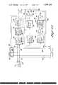
- FIGS. 2A through 2Ccombined is a block diagram of a control and monitoring station which can be used in the system of FIG. 1;
- FIG. 3is a block diagram of a subscriber room terminal which can be used in the system of FIG. 1;
- FIG. 4is a simplified block diagram of a head end equipment which can be used in the system of FIG. 1;
- FIG. 5illustrates a typical subscriber dialed program request of the present invention in one form and the dialing sequence of the various digits contained herein;
- FIG. 6illustrates a typical recorded printout delivered by the printer used in the system of FIG. 1.
- FIG. 1is a pictorial view of the complete television program request and distribution system including a central station 1, one of a plurality of guest rooms 2, and a PABX or private automatic telephone exchange equipment 3.
- Block diagrams of the various component parts of the system shown in FIG. 1are illustrated in greater detail in FIGS. 2 through 4 and their operation in the system will be disclosed herein later.
- the pulse duration and delay time periods illustrated in the herein described embodiment of the present inventionare typically based upon utilization of telephone signals provided by telephone equipment complying with well known telephone D.C. dial pulse and pulse train standards.
- standard telephone dial pulsesoccur at a rate of 8 to 10 pulses per second with each one of the pulses having a width of between 36 and 42% of a single pulse cycle.
- the minimum interdigital timeis 600 milliseconds. It will be understood by those skilled in the art that dial pulses having other than the standard characteristics can be used with corresponding changes in the illustrated duration and delay times.
- the disclosed systemcan be utilized with "touch-pad" type telephones by replacing the dial pulse processing circuitry with appropriate tone addressing circuitry.
- a central station 1which supplies and transmits free and premium program television signals to one or more subscriber locations or guest rooms 2 by means of the coaxial cable distribution network 4.
- the coaxial cable line taps 5are conventional and provide a means of supplying the television signals from the coaxial cable network 4 to each of a plurality of guest rooms 2 and associated equipment located within.
- a subscriber room terminal 8In addition to a standard or conventional television set 6 and telephone 7 which are normally provided in each guest room 2, there is also provided in accordance with the present invention, a subscriber room terminal 8, and a telephone signal pickup means 9.
- the television signals from the coaxial cable line tap 5are supplied to the subscriber room terminal 8 via the interconnecting signal cable 10 whereupon they are either converted or unconverted in frequency and supplied to the antenna input terminals 11 of the television set 6 via the antenna signal cable 12.
- the A.C. line power cord 13 from the television set 6interconnects to the hotel A.C. power line (not shown) within the subscriber room terminal 8.
- Telephone signals from the telephone pickup means 9are supplied to the subscriber room terminal 8 by means of the interconnecting signal cable 14.
- the pickup means 9 shown in FIG. 1is intended to represent an inductive type of pickup; however, other equally well known types may be used or the subscriber room terminal can be "hard wired" directly into the PABX telephone system 3 in accordance with accepted and standard telephone practices.
- the central station 1is comprised of a R.F. head end equipment 15 which operates to provide radio frequency television signals to the coaxial cable signal distribution network 4.
- the channel frequencies of the R.F. television signals provided by the head end 15are in two groups, the first being in a frequency range normally receivable by the guest room television set 6, and the second being in a frequency range not receivable by the television set 6 without first being converted in frequency.
- Television program material for distribution to guest room subscriberscan be supplied from public off-the-air television signals by means of antennas 16, 17 as well as from the video tape equipment 18, 19 and/or television camera equipment 20.
- the central station 1 of FIG. 1also comprises a control and monitoring station 21 and associated paper tape printer 22.
- control and monitoring station 21 and/or printer 22can be physically located elsewhere if convenience and desirability so dictate.
- the control and monitoring station 21is interconnected with the PABX telephone system 3 via an interconnecting telephone line 23.
- the control and monitoring station 21can also be connected to the head end equipment 15 via signal cable 24, the purpose of which will herein later be described.
- the PABX telephone system 3is conventional and typically comprises line switching equipment 25, in-house telephone lines 26 outside telephone lines 27 which normally connect to a central telephone exchange (not shown) outside the PABX system 3, one or more in-house or guest room subscriber telephone sets 7 and its respective individual telephone line 28 and terminal block 29.
- the PABX telephone system 3operates to provide connection of the control and monitoring station 21 with a given one of the subscriber telephone sets 7 upon a dialed access request from that telephone set.
- a PABX telephone system or the likeis utilized in the television system of the present invention, such PABX equipments are well known in the art and therefore a detailed explanation of its operation is not given.
- the only requirement of the PABX system 3is that it be capable of providing the connecting of a given subscriber telephone set 7 to the control and monitoring station 21 upon the subscriber dialing of a predetermined access number and, after the resulting connection of the subscriber telephone set 7 with the control and monitoring station 21 has been made, that the PABX system provide for any additional dialing pulses originating from the given subscriber's telephone set 7 to be transmitted to the control and monitoring station 21 for further processing.
- the PABX system 3can have the capability of supplying more than one interconnecting telephone line 23 to more than one corresponding control and monitoring station 21 in order that access calls can be accepted simultaneously from more than one subscriber telephone sets 7. This will provide for the simultaneous processing of subscriber program requests from a plurality of subscribers by a plurality of control and monitoring stations 21.
- any additional program request dialing pulses from the subscriber's telephone set 7will be processed by the control and monitoring station 21.
- the control and monitoring station 21will in turn send back to the subscriber telephone set 7 via the PABX system 3, enabling signals for activation of the subscribers room terminal 8 as will herein later be described.
- the predetermined access number which is dialed by the subscriber or room guest to gain access to the control and monitoring station 21is normally dictated by the PABX system 3 or more specifically by the line switching equipment 25. This access number may be any convenient digit such as for example, the number 6 could be used in the embodiment of the present invention which is described herein.
- FIG. 2Athe dialing of the access number at a given subscriber telephone set 7 will provide connection of that telephone set 7 with the control and monitoring station 21, as previously described.
- a low frequency telephone ringing signal provided by the PABX system 3will appear at the telephone line terminals 30 via the interconnecting telephone line 23.
- This ringing signalis in turn applied through the coupling capacitors 31 and 32 to the input of a ringing signal shaper amplifier 33 where it is shaped and amplified.
- Amplifier 33is normally enabled to pass the ringing signal at its input to its output but can be disabled or inhibited by application of an inhibiting signal at an inhibit terminal 34.
- the signal appearing at the output of the shaper amplifier 33 representing the ringing signalis provided as an input signal to a ringing signal detector 35.
- the detector 35detects the presence of the ringing signal at its input and in turn provides an output signal to a relay driver 36.
- the detector 35is capable of being latched to an ON state by the presence of the ringing signal at its input and remains in the ON state until it is reset by the application of a reset signal at its reset terminal 37.
- the detector 35provides an output signal to the relay driver 36 during that time that the detector 35 is latched in the ON state.
- the relay driver 36provides activation of a relay 38, thereby causing the contacts of the relay 38 to close from a normally open condition whenever the relay driver 36 is supplied with an output signal from the detector 35.
- the relay driver 36can be a D.C. amplifier with the electro-magnetic coil of the relay 38 in its output circuit.
- the contacts of relay 38are caused to close. The closing of these contacts places the series combination of resistor 39 and the secondary winding 40 (FIG. 2C) of a tone amplifier output transformer 41, across the telephone line input terminals 30 and associated telephone line 23.
- This resultant electrical loading of the telephone line 23is presented to the telephone switching equipment 25 and indicates to the PABX equipment that there is a "off-hook" condition or, in other words, that the control and monitoring station 21 has accepted the incoming call represented by the ringing signal.
- the output signal from the ringing signal detector 35is also applied to an input of a 300 millisecond mono-stable multivibrator 42 and a 15 second delay timer 43.
- the 300 millisecond mono-stable multivibrator 42operates to provide an output signal which changes to a high level state during a 300 millisecond time period duration after receiving its input signal from the ringing signal detector 35.
- the 300 millisecond output signal from the mono-stable multivibrator 42is applied to the inhibit terminal 34 of the ringing signal shaper amplifier 33 thereby preventing the ringing signal shaper amplifier 33 from providing any additional ringing signals to the input of the ringing signal detector 35 during the 300 millisecond time period.
- the 300 millisecond output signal from the mono-stable multivibrator 42is also applied to a signal input terminal 44 of an OR gate 45 (FIG. 2C) via the interconnecting lead 46 and to a signal input terminal 47 of an OR gate 48.
- operation of the OR gate 45 in response to the 300 millisecond signal at its input terminal 44provides the unclamping of junction point 49, of a voltage control oscillator control circuit 50, from a normally low or ground level to a level substantially equal to the positive voltage level present at the supply voltage terminal 51.
- the V.C.O. control circuit 50is comprised of a series combination of diode 52 and resistors, 53, 54, 55, and 56, connected between ground level and the supply voltage terminal 51.
- the unclamping of junction point 49causes the diode 52 to conduct, thereby providing a D.C. voltage to be applied to a frequency control terminal 57 of a voltage controlled audio tone oscillator or generator 58.
- the level of the voltage at the control terminal 57, and thus the output signal frequency of the V.C.O. 58,is set to a predetermined value by means of the adjustable resistor 54.
- the output signal from the generator 58is amplified by a tone amplifier 59 and passed by its output transformer 41 and interconnecting leads 60 to the telephone line terminals 30 whereupon it is supplied as a ready-tone to the requesting subscriber's room telephone set 7 via the telephone line 23 and PABX system 3.
- This ready-toneindicates to the requesting subscriber that the control and monitoring station 21 has responded to the incoming access request or ringing signal and is ready to process a program request from the requesting room telephone set 7.
- the dialed requestmust be made by the subscriber within a 15 second time period following the ready-tone as will be later apparent.
- the output signal frequency of generator 58 during the time period when the junction point 49 is clamped to ground level,is far outside the passband of the tone amplifier 59 and/or output transformer 41 and thus the unclamping of junction point 49 by the OR gate 45 for all practical purposes enables generator 58.
- the OR gate 48provides a reset output signal on interconnecting lead 61 in response to the 300 millisecond signal at its input terminal 47.
- This output signalis supplied to the reset terminals (R) of the digit pulse accumulator 104, digit sequence counter 90 and storage registers 96-100 shown in FIG. 2B via the interconnecting lead 61 and provides for the resetting of these pulse circuits to their initial states.
- the 15 second delay timer mono-stable MV 43operates to provide an output signal 15 seconds after it receives the output signal from the ringing detector latch 35.
- the output signal from the 15 second delay timer 43is supplied to a first signal input terminal 62 of an OR gate 63 and in response to this signal, the OR gate 63 provides an input signal to a 3 second error beep timer mono-stable MV 64.
- the 3 second timer 64upon receiving the input signal from the OR gate 63, operates to provide at a first output terminal 65, a first output signal having a 3 second time duration and at a second output terminal 66 a second output signal which is delayed for a 3 second time period after receiving the input signal from the OR gate 63.
- the first output signal from the 3 second timer 64 and appearing at the output terminal 65is supplied to a first input 67 of an AND gate 68 (FIG. 2C) via interconnecting line 69.
- a second input 70 of AND gate 68is provided by an error pulse multivibrator 71 which generates repetitive pulses at a low frequency rate of, for example, 10 Hz per second.
- OR gate 45a low frequency 10 Hz per second pulsed signal of 3 seconds time duration.
- This pulsed signalis supplied by OR gate 45 to the junction point 49 of the V.C.O. control circuit 50, thereby enabling generator 58, as previously described, at the 10 Hz per second rate for a time duration of 3 seconds.
- the output of generator 58is supplied as an error beep signal to the subscribers room telephone 7 as previously described and indicates to the requesting subscriber as will later be apparent, that an error in the subscriber request was made or that the subscriber request was not received by the control and monitoring station 21 within the required 15 second interval of time.
- the second output signal from the 3 second timer 64 and appearing at the output terminal 66is supplied to a first input terminal 72 of an OR gate 73.
- the OR gate 73in turn operates to provide an input signal to a second input terminal 74 of the OR gate 48 whereupon the operation of the OR gate 48 provides an output signal on the interconnecting lead 61 for resetting the pulse circuits shown in FIG. 2B as previously described.
- any pulse circuits which may have been activatedare again reset 18 seconds after the ring detector 35 detects the PABX ringing signal and supplies an output signal to the input of the 15 second delay timer 43.
- the output signal from OR gate 73 which is supplied to the second input terminal 74 of the OR gate 48is also supplied to the reset terminal 37 of the ring detector 35 whereby the ring detector 35 is also unlatched or reset.
- the resetting of the ring detector 35deactivates the relay 38 which signals the PABX system 3 that the call is terminated and that an "on-hook" condition exists.
- control and monitoring 21provides an off-hook condition to the PABX system 3 upon detecting the ringing signal from the PABX system 3.
- a ready tone signalis at this time provided and supplied to the PABX system 3 by the control and monitoring station 21.
- a reset signalis also provided to the pulse circuits of the control and monitoring station 21 for resetting the pulse circuits to their initial states.
- the subscriberwould normally proceed with his dialing request, however, if the subscriber fails to proceed with the dialing of his room, verification, and program request numbers or fails to complete this request within a 15 second time period immediately following the detection of the ringing signal and the initiation of the ready tone, the control and monitoring station 21 will provide to the PABX system 3 an error beep signal of 3 seconds time duration commencing 15 seconds after the control and monitoring station 21 detects the ringing signal.
- the ring detector latchwill be reset and a pulse reset signal will be provided to the pulse circuits of the control and monitoring station 21 for resetting any of the pulse circuits which may have been activated during the 15 second time period.
- the pulse circuits of the control and monitoring station 21can be reset prior to the above described 18 second time period by a signal at a second input terminal 75 of the OR gate 63 in which case the 3 second error beep signal will be provided as previously described to provide the operation of the OR gates 73 and 48 and the resulting presence of a reset signal on the interconnecting line 61. It will later be apparent that a signal at the second input terminal 75 of the OR gate 63 will be provided by an inverter amplifier 76 (FIG. 2B) whenever the subscriber dialed room and/or verification numbers are not proper.
- the pulse circuits of the control and monitoring station 21can be reset prior to the described 18 second period of time, by a signal on a second input terminal 77 of OR gate 73. In this case, however, the signal at the second input terminal 77 will not result in providing the 3 second error beep signal prior to the pulse reset signal on the interconnecting line 61. It will later be apparent that a signal at the second input terminal 77 of the OR gate 73 can be provided by the end of request decoder 78 (FIG. 2B) upon the completion of the processing by the control and monitoring station 21 of a proper subscriber room, verification and program request.
- the subscriberAfter the subscriber has dialed the access number and has received the ready tone, he proceeds with the dialing of his room, verification, and program request numbers.
- the resulting dial pulses from the requesting subscriber's telephone set 7are supplied to the telephone line terminals 30 of the control and monitoring station 21 by the PABX system 3, as previously described.
- the telephone dial pulses present at the telephone line terminals 30are supplied to a dial pulse shaper 79 for clipping the incoming dial pulses and for eliminating extraneous noises which may be present on the telephone line.
- the output of the pulse shaper 79(FIG. 2A) is applied to the input of a second pulse shaper 80 via the interconnecting lead 81.
- the pulse shaper 80comprises a mono-stable multivibrator which provides for each input dial pulse, an output signal pulse of 150 microseconds duration.
- the output of the pulse shaper 80will comprise a number of pulse trains, each train representing a different digit or number dialed by the subscriber and each train comprising one or more pulses.
- the output of the pulse shaper 80would comprise a series of five pulse trains with the number of pulses in each respective train being 4, 3, 5, 1, and 3.
- the output of the pulse shaper 80is applied to a first input 82 of an AND gate 83.
- the AND gate 83provides an output signal for each 150 microsecond input pulse appearing at its first input terminal 82, since the second input terminal 84 is normally at a high level as will herein later be apparent.
- the output signal of AND gate 83 representing each incoming dial pulse to the control and monitoring station 21is applied to the input of a 300 millisecond mono-stable multivibrator 85, as well as to the input of a digit pulse to binary counter 86 and a first input terminal 87 of an AND gate 88.
- the second input 89 of the AND gate 88will be described later.
- the 300 millisecond mono-stable MV 85provides an output signal pulse of 300 milliseconds duration for each input pulse; however, since more than one 150 microsecond input pulse from the AND gate 83 can occur within a single 300 millisecond period, the output of the 300 millisecond multivibrator 85 will, for all practical purposes, comprise a single continuous high level pulse starting with the first 150 microsecond input pulse and ending approximately 300 milliseconds after the last 150 microsecond input pulse of each pulse train received, representing each digit dialed by the subscriber.
- the output of the 300 millisecond mono-stable MV 85would comprise a series of five separate pulses, each pulse having respective approximate pulse widths of 700, 600, 800, 400, and 600 milliseconds.
- the above described signal output of the 300 millisecond MV 85is applied to an input of the end of request decoder 78 and to an input of a 3 bit digit pulse sequence counter 90, and inverter amplifier 239.
- the digit pulse sequence counter 90is a conventional 3 stage binary flip-flop circuit which converts the series of incoming pulses representing each of the subscriber dialed digits into binary count output signals. It counts the number of incoming digit pulses from the 300 millisecond mono-stable MV 85 and provides a 3 bit binary output signal for each incoming digit pulse.
- a binary oneis provided at the output for the first incoming digit pulse, and a binary two for the second incoming digit pulse and so on, up to and including a binary five for the fifth incoming digit pulse from the 300 millisecond mono-stable MV 85.
- This last or fifth digitrepresents the specific premium program requested by the subscriber in the embodiment disclosed.
- Each bit of the 3 bit binary output signal from the digit sequence counter 90is applied in parallel to an input of a digit sequence decoder 91 and to the end of request decoder 78.
- the end of request decoder 78operates to provide an output signal which changes from a normally low level state to a high level state at the end of the last digit dialed by the subscriber.
- the output signal of the end of request decoder 78would go high at the completion of the fifth digit dialed by the subscriber, i.e. the program digit 3.
- the end of request decoder 78will provide at its output a high level signal.
- the output of the end of request decoder 78is in a low level state.
- the output signal of the end of request decoder 78 in addition to being supplied to the AND gate 92, printer interface 93, and an interconnecting line 94is also supplied to the input of an inverter amplifier 95.
- the output of the inverter amplifier 95is in turn supplied to input terminal 84 of AND gate 83.
- the input terminal 84 of the AND gate 83will be at a high level thus permitting the AND gate 83 to provide output signals to the 300 millisecond mono-stable MV 85 as would be necessary to process new requests either from the same subscriber or new subscribers.
- the output of the end of request decoder 78is supplied to the input terminal 77 of the OR gate 73 (FIG. 2A).
- the OR gate 73will initiate the pulse circuits and ring detector 35 to be reset as previously explained.
- the digit sequence decoder 91operates on the binary output signals from the digit sequence counter 90 to provide corresponding output signals on successive ones of five output lines with the signal on each different output line representing the respective first, second, third, fourth, and fifth input digit pulse counted by the digit sequence counter 90.
- Each different digit output signali.e. representing first, second, third, fourth, and fifth digits and appearing on the respective one of the five output lines of the digit sequence decoder 91 is applied to an enable or store terminal (E) of a corresponding one of five binary storage registers 96, 97, 98, 99, and 100 for the respective first, second, third, fourth (verification), and fifth (program) digits.
- the 300 millisecond mono-stable MV 85, digit sequence counter 90, and digit sequence decoder 91operate to provide successive storage enabling signals to each one of the digit storage registers 96-100 at appropriate times, the purpose of which will be more apparent herein later.
- the digit pulse to binary counter 86is a 4 bit binary flip-flop circuit which converts the individual 150 microsecond pulses of each dialed digit from the AND gate 83 into a 4 bit binary output signal.
- the 4 bit binary output signals from the digit pulse to binary counter 86are applied in parallel to each one of the digit storage registers 96-100.
- the output of the 300 millisecond monostable MV 85is inverted by inverter amplifier 239 and is in turn applied to the reset terminal (R) of the counter 86.
- the output signal of the inverter amplifier 239thus resets the counter 86 at the end of each dialed digit when the output signal of the 300 millisecond mono-stable MV 85 returns to a low level state, i.e.
- the digit counter 86supplies a 4 bit binary signal for each of the five digits of the subscriber's dialed request to all 5 storage registers 96-100, only that digit storage register corresponding to a particular one of the five dialed digits will be enabled at the appropriate time so as to store only that 4 bit binary signal representing the respective digit number, i.e. for example, the digit storage register 96 is enabled to store only the binary number representing the first digit, storage register 97 is enabled to store only the 2nd digit binary number and so on up to storage of the fifth digit in storage register 100.
- the binary information stored in the storage registers 96-100 and representing the respective first through fifth digits dialed by the subscriber in making his premium program requestare supplied to a printer interface 93.
- Information signals related to the date and time of the specific program requestis also supplied to the printer interface 93 from a date and time clock 101.
- the printer interface 93converts the binary information from the storage registers 96-100 and the date and time information signals from the date and time clock 101 into output signals suitable for supplying to and activating a tape printer 22.
- the printer interface 93comprised a number of binary to decade decoders or converters for providing activation of the printer 22.
- the printer interface 93also receives an enabling signal input from the end of request decoder 78 which was described previously. This enabling signal signifies that the subscriber has completed his dialed request and this signal is utilized by the printer interface 93 to signal the printer 22 that it may record the information supplied to it by the printer interface 93.
- FIG. 6illustrates a typical printout of a subscriber's premium program request and is comprised of the requesting guest room number, the verification code number, and the specific premium program which was requested.
- the verification code numberis used to authenticate the subscriber request.
- the verification code numberis used to make certain that the subscriber request is being made by the room guest actually assigned to the so identified guest room. This minimizes the possibility of cheating and erroneous premium program charges which would result.
- a verification code numberis assigned to each subscriber guest room with the code number being a function of the guest room number.
- the control and monitoring station 21upon processing a guest room subscriber's request, compares the room number digits with the verification code digit and if the proper correlation exists provides enabling signals for transmission to the subscriber's room terminal 8 via the PABX system 3 and telephone set signal pickup means 9.
- verification code numbers used for the various guest room numbersare illustrated in the table below:
- room number 30would be assigned the code number 7 since the sum of the three digits, i.e. 0-3-, would equal 23.
- the room numbers 115, 104, and 300would also use the code number 7 since their three digit sums are 7, 15, and 23 respectively.
- the code numbers aboveare derived by (1) summing the 3 digits of the room number using 10 where no digit exists or where a zero digit exists; (2) expressing this sum as a binary number; (3) reversing the order of the last 3 bits of this binary number and (4) converting this reversed 3 bit number to an equivalent decimal type number. It should be understood that other verification code numbers and methods of deriving them are possible and within the spirit of the present invention.
- the output signals, from the digit sequence decoder 91, which are applied to the storage enabling terminals (E) of the storage registers 96, 97, 98 for the first, second, and third digit (room numbers digits)are also applied to three respective signal input terminals of an OR gate 103.
- the OR gate 103provides an output signal to the signal input terminal 89 of AND gate 88 so that each of the 150 microsecond digit pulses from the output of AND gate 83 and representing the first, second, and third room number digits and present at the signal input terminal 87 of AND gate 88, are applied at the output of AND gate 88 to an input of a room number digit accumulator 104.
- the accumulator 104sums or counts all of the pulses in the three room number digits and converts this sum to a binary number and provides as output signals the last 3 bits of the binary number.
- Each bit of the 3 bit binary output signal from the accumulator 104is supplied to respective first signal input terminals 105, 106, and 107 of the respective exclusive NOR gates 108, 109, and 110.
- the accumulator 104would provide the last 3 bits of a binary number representing the sum of the room number digits and more specifically would provide a 1 at signal input terminal 105, a 0 at terminal 106, and a 0 at terminal 107 of the respective exclusive gates 108, 109, and 110 which are the last three bits of binary 12.
- the verification digit storage register 99provides at its output a 3 bit binary number representing the dialed verification code number. Each bit of this 3 bit signal from the storage register 99 is applied in reverse order to respective second signal input terminals 113, 112, 111 of the exclusive NOR gates 110, 109, and 108. Thus, for the verification code number 1 as illustrated in FIG. 6, binary inputs of 0, 0, 1 are applied to the respective signal input terminals 113, 112, and 111 of the exclusive NOR gates 110, 109, and 108.
- the exclusive NOR gates 108, 109, and 110each provide identical signals to each of the signal input terminals of the AND gate 92 so as to provide a high level logic signal at the output of the AND gate 92 when the signal in interconnecting lead 114 from the end of the request decoder 78 is high.
- the exclusive NOR gates 108, 109, 110 and the AND gate 92therefore operate as a comparator with the signal output of the AND gate 92 appearing on the lead 115, indicative of either proper or improper room number and verification code number, i.e. a valid or invalid subscriber request.
- the signal on lead 115will be a high level signal when proper verification occurs.
- the program digit decoder 117converts the binary coded number, representing the requested program, to an output signal on a predetermined one of a plurality of output lines 119-124.
- the output of the decoder 117appears on one of the six output lines 119-124 depending upon the particular program number requested.
- the request for a program number 1 through 6will appear as an output signal from the decoder 117 on a respective output line 119-124.
- a high level output signalwill be provided on line 121 when the premium program number 3 has been requested as illustrated in FIG. 6.
- Each one of the output lines 119-124is connected to a first signal input terminal of a respective AND gate 125-130.
- the second signal input terminals of all of the AND gates 125-130are common to one another and are connected to the output of AND gate 92 (FIG. 2B) via the interconnecting line 115.
- a third signal input terminal of each one of the AND gates 125-130is connected to a respective carrier detector 131-136 (FIG. 4) in the head end equipment 15 via a respective one of the interconnecting lines 137-142.
- a high level signal on any one of the lines 137-142indicates that the head end equipment 15 is at the time providing to the coaxial cable distribution network 4 the respective premium television program.
- any one of the AND gates 125-130will provide a high level output signal whenever high level signals are also present at its first and third signal inputs.
- the signal outputs of the AND gates 125-130are connected to and supply input signals to a respective one of program mono-stable multivibrators 143-148 which, in turn, supply input signals to OR gates 149-152.
- Each one of the program mono-stable multivibrators 143-148provide an input signl to a selected pair of OR gates 149-152.
- the output of each OR gate 149-152is connected to a V.C.O. control circuit 153-156.
- OR gates 149-152 and V.C.O. control circuits 153-156are similar to that previously described for OR gate 45 and V.C.O. control circuit 50 and provide for the unclamping of the corresponding junctions points and the enabling of a respective generator 58, 157, 158, and 159.
- the unlabeled adjustable resistors shown in each of the control circuits 153-156 of FIG. 2Coperate the same as the adjustable resistor 54 in the previously described control circuit 50 and each adjustable resistor is adjusted to provide a predetermined signal output frequency from each respective voltage controlled oscillator 58, 157, 158, and 159 when enabled by its respective control circuit 153-156.
- the enabling tone output signal frequencies of f 1 ,f.sub. 2,f.sub. 3, and f 4will be provided by the respective voltage controlled oscillators 58, 157, 158, and 159 when each is enabled by its respective control circuit 153, 154, 155, and 156.
- any two of the four voltage controlled oscillators 58, 157, 158, and 159will provide six different possible tone combinations; therefore, six different premium programs may be made available for subscriber selection.
- the six available premium programs numbered 1 through 6correspond to the enabling of the respective pairs of tone generators (58, 157); (58, 158); (58, 159); (157, 158); (157, 159); and (158, 159).
- the six available premium programs numbered 1 through 6are represented by the respective pairs of output frequencies (f 1 ,f 2 ); (f 1 , f 3 ); (f 1 , f 4 ); (f 2 , f 3 ); (f 2 , f 4 ); and (f 3 , f 4 ).
- a high level signalwill be present on the output line 121 from the decoder 117 and line 139 from the carrier detector 133.
- These signals on lines 121 and 139 in combination with a high level verification signal on line 115will cause the AND gate 127 to trigger the mono-stable MV 145.
- the output signal from the monostable MV 145provides operation of the OR gates 149 and 152 thereby, in turn, providing for the unclamping of the respective control circuits 153 and 156 and the enabling of the V.C.O. tone generators 58 and 159.
- the pair of output signals, f 1 and f 4 , from the respective V.C.O. tone generators 58 and 159are provided as input signals to the tone amplifier 59 whereupon they are amplified and supplied as enabling signals or tones to the telephone lines 23 via the output transformer 41, interconnecting lines 60, relay 38, resistor 39 and line terminals 30.
- These enabling tonesare supplied to the subscriber's telephone set 7 by the PABX system 3 and, in turn, supplied to the subscriber's room terminal 8 via the telephone pickup means 9 and signal cable 14.
- the inventionis not limited to the above illustrated number of output frequencies and more or less than the described four can be used with, of course, resulting changes in the number of different tone combinations available.
- the tone combinationsneed not be limited to pairs of tones and may, for example, comprise triplets or single tones.
- Nthe number of available different tone combinations
- Nthe number of available different tone combinations
- generator 58serves a multi-purpose function since it is used to provide an enabling tone f 1 as well as ready and error tones. Separate voltage controlled oscillators could of course be utilized for these purposes. In addition it should be understood that although four voltage controlled oscillators 58, 157, 158, and 159 are utilized in the disclosed embodiment to provide enabling tones, a greater or lesser number of such voltage controlled oscillators may be used with appropriate changes elsewhere in the system without departing from the scope and spirit of the present invention.
- FIG. 1there is illustrated in block diagram a subscriber room terminal 8.
- the R.F. television signals which are generated at the head end equipment 15are received at the R.F. signal input terminal 160 of the subscriber room terminal 8 by means of the coaxial cable distribution network 4, and the subscriber's line tap 5 and the interconnecting signal cable 10.
- the enabling tone signals generated by the control and monitoring station 21 and transmitted to the subscriber telephone set 7are received at the enabling tone input terminal 161 by means of the telephone signal pickup means 9 and interconnecting cable 14.
- the antenna input terminals 11 of the subscriber's television set 6are connected to the R.F. signal output terminal 162 of the subscriber's room terminal 8 by means of the antenna signal cable 12.
- A.C. power input to the subscriber room terminal 8is supplied from A.C. power mains (not shown) to the A.C. power input terminals 164 in FIG. 3.
- A.C. power mains(not shown) to the A.C. power input terminals 164 in FIG. 3.
- the R.F. television signals which are transmitted from the head end equipment 15 to the various subscriber room terminals 8 in the systemare comprised of both free and premium program channels.
- the subscriber room terminal 8upon receiving enabling tones from the control and monitoring station 21, provides an automatic frequency conversion of a subscriber requested one of the premium program R.F. channels which is not normally receivable by the subscriber's television set 6, to a predetermined R.F. channel having a frequency which can be received by the subscriber's television set 6.
- the enabling tones present at the enabling tone input terminal 161are supplied to the input of a band pass filter 165.
- the band pass filter 165operates to pass to its output, only those signals within the frequency range encompassed by the four signal output frequencies f 1 , f 2 , f 3 , and f 4 of the four voltage controlled oscillators 58, 157, 158, and 159 in the control and monitoring station 21.
- These signal output frequencies of the voltage controlled oscillators 58, 157, 158, and 159are those signal frequencies supplied to the telephone line 23 by each respective V.C.O. when enabled by the unclamping of the junction points of the respective V.C.O.
- the band pass filter 165thus eliminates from its output, undesired or spurious signals which may be present at the input terminal 161.
- the output signals of the band pass filter 165are provided as input signals to each one of four enabling tone detector circuits.
- Each enabling tone detector circuitoperates to provide a D.C. output signal on its respective signal output line 170-173 whenever a signal is supplied to its input which is within the band pass frequency range of a respective band pass filter 174-177.
- the enabling tone detector circuitsare substantially equivalent to one another.
- the respective amplifiers 178-181provide amplification of input signals supplied from the band pass filter 165 and in addition provide circuit isolation or buffering between the band pass filter 165 and the respective individual band pass filters 174-177 of the enabling tone detector circuits.
- the detectors 182-185can each comprise a simple diode detector circuit to detect an incoming enabling tone and provide a D.C. output voltage in response thereto.
- the band pass filters 174-177each operate to pass enabling tone frequencies different from one another.
- the band pass filter 174operates to pass only the enabling tone f 1 generated by voltage control oscillator 58 in the control and monitoring station 21.
- the respective filters 175, 176 and 177operate to pass only the respective enabling tones of f 2 , f 3 , and f 4 which are generated by the corresponding voltage controlled oscillators 157, 158, and 159.
- the D.C. output signalswhich appear on the detector output lines 170, 171, 172, and 173 are indicative of the frequency of the enabling tones supplied to the input terminal 161 from the control and monitoring station 21.
- output signal on the output line 170indicates the presence of an enabling tone input signal f 1 .
- output signals on the lines 171, 172, and 173indicate the presence of input signals having respective frequencies of f 2 , f 3 , and f 4 . Therefore, a specific pair of enabling tones corresponding to a requested premium program number for which the control and monitoring station 21 is responding, is identifiable by the D.C. output signals present on any two of the four output lines 170-173.
- a subscriber request for the premium program number 3 as illustrated in FIG. 6,will as previously described, result in the presence of a pair of enabling tones f 1 and f 4 at the input terminal 161 of the subscriber's room terminal 8.
- This pair of enabling tones f 1 and f 4are passed by the band pass filter 165 and in turn supplied as input signals to each of the enabling tone detector circuits. Since only the enabling tone detector circuit 182 will respond to the enabling tone f 1 and detector circuit 185 to the tone f 4 , a pair of D.C. output signals will be provided only on the corresponding output lines 170 and 173.
- the output signals from the enabling tone detector circuitsare supplied as input signals to a decoder.
- the decoderis comprised of AND gates 187-192 with each gate having a respective one of signal output lines 193-198.
- the output signals appearing on lines 170-173 from the respective enabling tone detectorsare supplied to the AND gates 187-192 of the decoder such that for any particular pair of enabling tones to the input terminal 161 of the subscriber's room terminal 8, only one of the AND gates 187-192 corresponding to that pair of enabling tones, will provide an output signal on its corresponding signal output line.
- an output signal from the decoder on any one of the output lines 193-198is related to a respective and corresponding one of the requested premium program numbers and its respective pair of enabling tones.
- an output signal on line 193is related to the premium program number 1; an output signal on line 194 is related to the program number 2 and so on up to and including output line 198 which relates to program number 6.
- each respective AND gate 187-192is supplied to a SET (S) input terminal of a respective program latch 199-204.
- Each program latch 199-204upon receiving a SET input signal from its respective AND gate 187-192 latches to an ON state and remains in that state until receiving a signal at its RESET, (R) terminal at which time it returns to its RESET or OFF state.
- RRESET,
- a signal output from the respective latch 199-204is supplied to a respective one of input terminals 205-210 of a converter control means.
- the latches 199-204are identical to one another and each can comprise a conventional flip-flop type latch circuit operating with high level input signals and providing high level output signals.
- the converter control meansoperates to provide a selected one of a number of presetable D.C. voltage levels at the control voltage input terminals 212, 213 of the voltage tuned premium channel R.F. converter 214 in response to the application of an input signal to a particular one of a corresponding number of signal input terminals 205-210.
- the converter control means in the embodiment shown in FIG. 3is comprised of six adjustable D.C. voltage divider circuits with each one of the divider circuits corresponding to each one of the six input terminals 205-210.
- Each one of the six divider circuitsis comprised of an adjustable resistor 215 connected in series with a single common resistor 216.
- Each of the six divider circuitsfurther comprises transistor switch 217 with its collector-emitter path connected in series with the corresponding adjustable resistor 215.
- Each one of the six series connected adjustable resistors 215 and corresponding transistor switches 217are connected in parallel with one another. This parallel combination is, in turn, connected in series with the common resistor 216.
- each one of the transistor switches 217is biased to be normally non-conducting with no signal input at its corresponding input signal terminal 205-210.
- the application of an input signal to any selected one of the input terminals 205-210,will cause the corresponding transistor switch 217 to be driven into conduction, thereby causing the voltage divider comprised of the corresponding adjustable resistor 215 and the common resistor 216 to be connected across the D.C. voltage source at terminals 218, 219.
- the resulting D.C. voltage level existing between the junction point of the voltage divider resistors 216, 215, and the D.C. source terminal 219is applied to the varactor control voltage terminals 212, 213 of the converter 214.
- the converter control means shown in FIG. 3can provide any one of six different preset voltage levels by the application of an input signal to a corresponding one of the six signal input terminals 205-210 from the corresponding latches 199-204.
- the premium channel R.F. converter 214provides for the frequency comversion of all of the incoming premium program channels applied at the R.F. input terminal 160, to a single output channel frequency at the R.F. output terminal 162.
- any incoming premium program channel located between channels 6 and 7 of the standard V.H.F. television bandcan be converted to a single output channel such as for example, the standard television channel 12.
- the premium channel R.F. converter 214can be of conventional and well known design which utilizes voltage controlled capacitors or varactors for the control and adjustment of frequency.
- the application of selected levels of D.C. voltage at the terminals 212, 213provide for the tuning of the converter so as to enable the conversion of the available incoming premium program channels to a predetermined output channel which can be received by the subscribers television set 6.
- Each of the adjustable resistors 215 of the converter control meanscan therefore be preset to provide a voltage level at terminals 212, 213 to cause the converter 214 to tune to a different and desired incoming premium program channel.
- Each of these voltage levelsare selected by the application of a signal to a selected one of the input terminals 205-210 as previously described.
- the R.F. filter 220provides a low impedance signal path from the R.F. input terminal 160 to the R.F. output terminal 162 for incoming television channels other than the premium program channels.
- the V.H.F. channels 2 through 6, 7 through 13would be passed with little or no attenuation from the R.F. input terminal 160 to the R.F. output terminal 162.
- the R.F. filter 220thus is a low impedance shunt across the premium channel converter 214 for R.F. channels other than the midband premium channels.
- the R.F. filter 220may of course be an integral part of the converter 214 and can be a hybrid filter or the like. The function of the R.F.
- filter 220can also be provided by a frequency selective signal splitter whereby only those incoming signals at the R.F. input terminal 160 which are within the frequency band used for transmission of the premium program channels, are routed to the input of the premium program converter 214 and whereby all other signals are routed directly to the R.F. output terminal 162.
- the subscriber room terminal 8also includes circuitry for providing reset signals to the RESET, (R) signal terminals of each of the latches 199-204.
- Output signals from each of the six AND gates 187-192are supplied as input signals to an OR gate 221.
- An output signal from a television set load sensor 222is also supplied as an input signal to the OR gate 221 via the sensor signal output line 223.
- the output signal from the OR gate 221is applied to the input of a signal differentiator 224.
- the output of the signal differentiator 224is applied simultaneously to the RESET, (R) signal input terminals of all of the latches 199-204.
- the above described reset signal circuitryoperates to provide a momentary reset signal to each of the latches 199-204, each time an output signal appears at the output of any one of the AND gates 187-192 or each time that the subscriber television set is turned off.
- the television set load sensor 222provides a normally low level signal on its output line 223 when the television set is ON, i.e. when the A.C. power switch is in the ON position.
- Each time the television set 6 is turned OFF by the subscriber the load sensor 222provides a high level signal to the OR gate 221 via the output line 223.
- the OR gate 221provides a high level output signal to the differentiator 224 whenever a high level signal is applied to any of its inputs.
- the differentiator 224differentiates its input signal from the OR gate 221 and provides a short duration high level pulse to the RESET, (R) terminals of the latches 199-204.
- the differentiator 224can be a conventional RC type differentiator whereby the output of the OR gate 221 is capacity coupled to the RESET, (R) terminals or it can be a digital type differentiator circuit such as comprised of an exclusive OR gate having one of its two inputs connected directly to the output of the OR gate 221 and its other input connected to the output of the OR gate 221 through a momentary delay device such as one or more non-inverting amplifiers.
- the signal output pulse obtained from the output of the exclusive OR gateis of course supplied to the latches 199-204 as reset signals.
- the differentiator 224it is a requirement of the differentiator 224 that it provide an output signal pulse with a time duration much less than the duration of the incoming enabling signals supplied to the input terminal 161 of the subscriber's room terminal 8.
- the reset pulse width in one embodimentwas approximately 5 microseconds compared to the enabling tone duration of several milliseconds. Since the latches 199-204 normally cannot be latched by signals on the SET, (S) input terminals while there is a signal present on the RESET, (R) terminal, the purpose of a short duration reset pulse signal is obvious.
- the television set load sensor 222in one simple form can comprise an electromagnetic relay 225 and a source of D.C. voltage 226.
- the electromagnetic coil of relay 225is connected in series with one lead 227 of the A.C. power line cord 13 which supplies A.C. power to the subscriber's television set 6.
- load currentcauses the relay 225 to be energized thereby supplying a low level signal to the OR gate 221 via the output line 223 and relay contact 228.
- the relay 225is de-energized and a high level signal is supplied to the OR gate 221 via the output line 223 and relay contact 229 from the D.C.
- the load sensor shown in FIG. 3is by way of example only and many other suitable circuits may be used which will be obvious to those skilled in the art, to sense the ON-OFF condition of the subscriber television set and to provide the necessary input signal to the OR gate 221 in response thereto.
- FIG. 4a typical head end equipment 15 which can be used in the herein disclosed television signal distribution system of the present invention to provide R.F. television channel output signals in the standard V.H.F. television frequency band as well as in the mid-band V.H.F. range.
- the output signals from the head end equipment 15are supplied to the coaxial cable distribution network 4 for distribution to the various guest rooms and subscriber room terminals in the system.
- the head end equipment 15is comprised of various R.F. signal carrier generators, modulators, R.F. signal combiners and the like which are conventional and well known in the C.A.T.V. art and are therefore not described in detail.
- the carrier detectors 131-136which are shown as part of the head end equipment 15, although conventional in design, are not normally included in commercially available C.A.T.V. head end equipment and will be described herein later.
- the various signal inputs to the input terminals 230-238 of the head end equipment 15 shown in FIG. 4are illustrative examples of what can be utilized in a typical installation of the present invention for distribution of programs to the subscriber rooms and room terminals; the invention, however, is not limited thereto.
- Radio frequency signals from television broadcast stationscan be provided at the signal input terminals 230 and 231.
- These R.F. input signals at the input terminals 230, 231can be supplied by the head end equipment 15 to the coaxial cable network 4, either converted or unconverted in channel frequency as may be desired.
- Video and accompanying audio signalscan be provided at the signal input terminals 232-238. These signals supplied to the input terminals 232-238 are of course used to modulate R.F. carriers generated within the head end equipment 15.
- the frequencies of these generated carrierscan of course be located in the standard V.H.F. band and/or the midband range as may be desired.
- the signals provided at input terminals 230-232are used as free program material whereas those signals at the input terminals 233-238 are used as premium program material.
- the described embodiment of the control and monitoring station 21 and the subscriber room terminal 8both have the capability of six separate premium program channels, a greater or lessor number can be provided.
- the head end equipment 15 shown in FIG. 4can be modified by those skilled in the art, to provide additional premium program channels as necessary.
- the carrier detectors 131-136operate to provide output signals on their respective output signal lines 137-142 which output signals are indicative of whether or not the respective premium program channel carriers or signals are being generated and supplied by the head end equipment 15 to the coaxial cable distribution network 4, for distribution to the subscriber rooms.
- the carrier detectors 131-136are identical to one another and each one can comprise a simple R.F. diode detector circuit to detect the presence of a R.F. carrier signal at the output of a respective premium program R.F. carrier generator and in turn provide a high level output signal on its respective output line 137-142 which output signal is indicative of the presence of the respective premium program R.F. carrier signal.
- the output signals from the carrier detectors 131-136are supplied to the control and monitoring station 21 by the respective signal lines 137-142 and can be utilized by the control and monitoring station 21 to prevent the processing and consequent billing of a subscriber request for a premium program channel which, at the time of the subscriber request, is not being generated or transmitted by the head end equipment 15.
- carrier detectors 131-136can be omitted if desired, in which case each one of the AND gates 125-130 (FIG. 2C) would be replaced by a two input AND gate and the interconnecting leads 137-142 omitted.
- FIG. 5illustrates and summarizes in pictorial form the dialing sequence of a typical subscriber request for a premium program including the relative positions of the various tones involved in such a request, all of which have been previously described in detail in relation to the operation of the disclosed embodiment of the invention.
- FIG. 6illustrates a typical paper tape printout or record of a typical subscriber premium program request as supplied by the paper tape printer. Although the time and date of the request is not illustrated in this figure, it should be understood that such information can be contained in the printed record.
- the premium program television signalscan originate from locations other than the central station shown in FIG. 1.
- the systemcan be integrated with an external or separate public cable television system whereby some or all of the free and/or premium television programs are supplied by the public cable system either to the head end equipment 15 or directly to the subscriber terminal 8.
- the enabling signals generated by the control and monitoring station 21can also be used to enable unscramblers or other types of premium program decoders.
Landscapes
- Engineering & Computer Science (AREA)
- Signal Processing (AREA)
- Multimedia (AREA)
- Databases & Information Systems (AREA)
- Human Computer Interaction (AREA)
- Telephonic Communication Services (AREA)
Abstract
Description
______________________________________ SUM OF 3 DIGITS OF ROOM NUMBER VERIFICATION (no digit and zero equal to 10) CODE NUMBER ______________________________________ 3, 11, 19, 27 6 4, 12, 20, 28 1 5, 13, 21, 29 5 6, 14, 22 3 7, 15, 23 7 8, 16, 24 8 9, 17, 25 4 10, 18, 26 2 ______________________________________
N = (n.sup.2 - n/2)
Claims (6)
N = (n.sup.2 -n)./2
Priority Applications (1)
| Application Number | Priority Date | Filing Date | Title |
|---|---|---|---|
| US05/554,347US4008369A (en) | 1975-02-28 | 1975-02-28 | Telephone interfaced subscription cable television system especially useful in hotels and motels |
Applications Claiming Priority (1)
| Application Number | Priority Date | Filing Date | Title |
|---|---|---|---|
| US05/554,347US4008369A (en) | 1975-02-28 | 1975-02-28 | Telephone interfaced subscription cable television system especially useful in hotels and motels |
Publications (1)
| Publication Number | Publication Date |
|---|---|
| US4008369Atrue US4008369A (en) | 1977-02-15 |
Family
ID=24212993
Family Applications (1)
| Application Number | Title | Priority Date | Filing Date |
|---|---|---|---|
| US05/554,347Expired - LifetimeUS4008369A (en) | 1975-02-28 | 1975-02-28 | Telephone interfaced subscription cable television system especially useful in hotels and motels |
Country Status (1)
| Country | Link |
|---|---|
| US (1) | US4008369A (en) |
Cited By (138)
| Publication number | Priority date | Publication date | Assignee | Title |
|---|---|---|---|---|
| US4161751A (en)* | 1977-05-19 | 1979-07-17 | Ost Clarence S | High-security cable television access system |
| US4258386A (en)* | 1978-07-31 | 1981-03-24 | Cheung Shiu H | Television audience measuring system |
| US4268859A (en)* | 1977-05-19 | 1981-05-19 | Ost Clarence S | High-security cable television access system |
| US4303937A (en)* | 1979-07-30 | 1981-12-01 | Cook Tommy D | Communication system for supplementing off-air or cable TV signals with locally generated video messages |
| US4320256A (en)* | 1979-11-27 | 1982-03-16 | Freeman Michael J | Verbally interactive telephone interrogation system with selectible variable decision tree |
| US4326221A (en)* | 1980-09-30 | 1982-04-20 | Mallos Gene G | Central/remote television monitoring system |
| US4396947A (en)* | 1979-02-20 | 1983-08-02 | Payview Limited | Apparatus for encoding of information |
| US4430669A (en) | 1981-05-29 | 1984-02-07 | Payview Limited | Transmitting and receiving apparatus for permitting the transmission and reception of multi-tier subscription programs |
| WO1984000863A1 (en)* | 1982-08-19 | 1984-03-01 | World Video Library Inc | Recorded program communication system |
| US4527204A (en)* | 1982-02-12 | 1985-07-02 | Sony Corporation | Remote control system |
| FR2560473A1 (en)* | 1984-02-23 | 1985-08-30 | American Telephone & Telegraph | METHOD AND DEVICE FOR DIFFUSION OF SIGNALS BY SUBSCRIPTION |
| US4547851A (en)* | 1983-03-14 | 1985-10-15 | Kurland Lawrence G | Integrated interactive restaurant communication method for food and entertainment processing |
| EP0161997A1 (en)* | 1984-04-05 | 1985-11-21 | Federation De L'institut Arnault Tzanck | Apparatus for controlling at least one device from at least one telephone connected to an exchange |
| FR2570050A1 (en)* | 1984-07-20 | 1986-03-14 | Messerschmitt Boelkow Blohm | Passenger cabin management in aircraft |
| US4584603A (en)* | 1984-10-19 | 1986-04-22 | Harrison Elden D | Amusement and information system for use on a passenger carrier |
| DE3438293A1 (en)* | 1984-10-19 | 1986-04-24 | Telefonbau Und Normalzeit Gmbh, 6000 Frankfurt | Method and circuit arrangement for detecting chargeable use of television sets |
| US4590516A (en)* | 1982-06-01 | 1986-05-20 | World Video Library, Inc. | Recorded program communication system |
| FR2574370A2 (en)* | 1984-12-08 | 1986-06-13 | Messerschmitt Boelkow Blohm | METHOD AND DEVICE FOR PERFORMING, ON BOARD AN AIRPLANE, FUNCTIONS CONCERNING PASSENGERS AND ACCOMPANYING STAFF |
| DE3522385A1 (en)* | 1985-06-22 | 1987-01-02 | Blg Landsmann Gmbh | Multi-position television system, in which a centre is connected by cable to a plurality of terminal units |
| FR2591837A1 (en)* | 1985-12-12 | 1987-06-19 | Pizon Ernest | Device for encoding and decoding a video transmission |
| DE3717261A1 (en)* | 1987-05-22 | 1987-11-19 | Paul Bamberg | Method for selecting television programmes by telephone |
| US4734764A (en)* | 1985-04-29 | 1988-03-29 | Cableshare, Inc. | Cable television system selectively distributing pre-recorded video and audio messages |
| US4796297A (en)* | 1983-08-19 | 1989-01-03 | Nec Corporation | Device for calculating a charge for a charged information signal with errors avoided in a report of the charge |
| US4829560A (en)* | 1987-01-30 | 1989-05-09 | Spectradyne | Communications system for use in a hotel/motel |
| US4852154A (en)* | 1986-02-04 | 1989-07-25 | Pacific Bell | Pay-per-view CATV system |
| EP0264553A3 (en)* | 1986-10-13 | 1989-09-13 | Telenorma Telefonbau Und Normalzeit Gmbh | Remote control device |
| DE3808657A1 (en)* | 1988-03-15 | 1989-10-05 | Nixdorf Computer Ag | INFORMATION DISTRIBUTION SYSTEM |
| US4890320A (en)* | 1988-06-09 | 1989-12-26 | Monslow H Vincent | Television broadcast system for selective transmission of viewer-chosen programs at viewer-requested times |
| US4890322A (en)* | 1984-02-23 | 1989-12-26 | American Telephone And Telegraph Company | Method and apparatus for subscription broadcast |
| US4893248A (en)* | 1987-02-06 | 1990-01-09 | Access Corporation | Monitoring and reporting system for remote terminals |
| US4995078A (en)* | 1988-06-09 | 1991-02-19 | Monslow H Vincent | Television broadcast system for selective transmission of viewer-chosen programs at viewer-requested times |
| US4994908A (en)* | 1988-12-23 | 1991-02-19 | Scientific-Atlanta, Inc. | Interactive room status/time information system |
| US5001554A (en)* | 1988-12-23 | 1991-03-19 | Scientific-Atlanta, Inc. | Terminal authorization method |
| US5016272A (en)* | 1989-06-16 | 1991-05-14 | Stubbs James R | Home video system |
| US5027426A (en)* | 1989-07-07 | 1991-06-25 | Chiocca Jr Joseph J | Signal coupling device and system |
| US5113496A (en)* | 1987-08-04 | 1992-05-12 | Mccalley Karl W | Bus interconnection structure with redundancy linking plurality of groups of processors, with servers for each group mounted on chassis |
| US5191410A (en)* | 1987-08-04 | 1993-03-02 | Telaction Corporation | Interactive multimedia presentation and communications system |
| EP0494530A3 (en)* | 1991-01-11 | 1993-04-21 | Strategic Telecom, Inc | System for accessing amenities through a public telephone network |
| WO1993013630A1 (en)* | 1991-12-20 | 1993-07-08 | Square D Company | Distribution system for communication services |
| US5327554A (en)* | 1990-11-29 | 1994-07-05 | Palazzi Iii Michael A | Interactive terminal for the access of remote database information |
| US5341216A (en)* | 1989-09-29 | 1994-08-23 | Saskatchewan Telecommunications | CATV channel access control and metering apparatus |
| US5469495A (en)* | 1993-05-28 | 1995-11-21 | U S West Advanced Technologies, Inc. | Method and apparatus for delivering secured telephone service in hybrid coaxial cable network |
| US5475740A (en)* | 1993-03-11 | 1995-12-12 | Spectradyne, Inc. | System for accessing and paying for amenities using a telephone |
| US5555441A (en)* | 1994-08-02 | 1996-09-10 | Interim Design Inc. | Interactive audiovisual distribution system |
| US5592540A (en)* | 1993-05-28 | 1997-01-07 | U S West Advanced Technologies, Inc. | Method and apparatus for selectively delivering telephony signals on a hybrid coaxial cable network |
| US5615246A (en)* | 1993-05-28 | 1997-03-25 | Us West Technologies, Inc. | Method and apparatus for spurious signal detection and disconnection in a hybrid fiber/coax network architecture |
| US5642418A (en)* | 1995-02-21 | 1997-06-24 | Bell Atlantic Network Services, Inc. | Satellite television system and method |
| US5661517A (en)* | 1994-05-02 | 1997-08-26 | Messagephone, Inc. | Interactive intelligent video information system |
| US5717452A (en)* | 1993-09-09 | 1998-02-10 | Alcatel N.V. | Interactive control system for multiservice installations including a television program distribution server and a PABX |
| US5887243A (en) | 1981-11-03 | 1999-03-23 | Personalized Media Communications, L.L.C. | Signal processing apparatus and methods |
| US5907715A (en)* | 1994-08-10 | 1999-05-25 | Lodgenet Entertainment Corporation | Entertainment system for collecting user inputs by periodically interleaving game collection interrogations into series of system interrogations during interruption of system interrogations |
| US6009465A (en)* | 1996-01-22 | 1999-12-28 | Svi Systems, Inc. | Entertainment and information systems and related management networks for a remote video delivery system |
| US6121998A (en)* | 1992-02-19 | 2000-09-19 | 8×8, Inc. | Apparatus and method for videocommunicating having programmable architecture permitting data revisions |
| USRE36988E (en)* | 1988-12-23 | 2000-12-12 | Scientific-Atlanta, Inc. | Terminal authorization method |
| US20020071531A1 (en)* | 1989-07-14 | 2002-06-13 | Inline Connections Corporation, A Virginia Corporation | Video transmission and control system utilizing internal telephone lines |
| EP1289294A1 (en)* | 2001-08-16 | 2003-03-05 | Citeservice | Interactive transmission system for a multimedia web guide and method implemented in such a system |
| US6574798B1 (en) | 1999-02-03 | 2003-06-03 | Sasktel | System and controller for control and distribution of audio and video signals |
| US20030139980A1 (en)* | 2002-01-24 | 2003-07-24 | Hamilton Robert Douglas | Method and system for providing and controlling delivery of content on-demand over a cable television network and a data network |
| US20030147513A1 (en)* | 1999-06-11 | 2003-08-07 | Goodman David D. | High-speed data communication over a residential telephone wiring network |
| US20030165220A1 (en)* | 1989-07-14 | 2003-09-04 | Goodman David D. | Distributed splitter for data transmission over twisted wire pairs |
| US20040101337A1 (en)* | 2000-05-12 | 2004-05-27 | Michel Woodman | Printer |
| US20040125819A1 (en)* | 2001-07-05 | 2004-07-01 | Yehuda Binder | Telephone outlet with packet telephony adapter, and a network using same |
| US20040156224A1 (en)* | 2002-01-03 | 2004-08-12 | Buer Myron J. | Method and apparatus for verification of a gate oxide fuse element |
| US20040199909A1 (en)* | 1999-07-27 | 2004-10-07 | Inline Connection Corporation | Universal serial bus adapter with automatic installation |
| US20040230710A1 (en)* | 1999-07-27 | 2004-11-18 | Inline Connection Corporation | System and method of automatic installation of computer peripherals |
| US20050008033A1 (en)* | 2000-04-18 | 2005-01-13 | Serconet Ltd. | Telephone communication system over a single telephone line |
| US20050010954A1 (en)* | 2003-07-09 | 2005-01-13 | Serconet Ltd. | Modular outlet |
| US20050034168A1 (en)* | 1993-05-28 | 2005-02-10 | Mediaone Group, Inc. | Method and apparatus for delivering secured telephony service in a hybrid coaxial cable network |
| US20050047431A1 (en)* | 2001-10-11 | 2005-03-03 | Serconet Ltd. | Outlet with analog signal adapter, a method for use thereof and a network using said outlet |
| US20050060405A1 (en)* | 2002-09-16 | 2005-03-17 | Guy Nathan | Digital downloading jukebox system with central and local music servers |
| US20050111636A1 (en)* | 1999-07-20 | 2005-05-26 | Serconet, Ltd | Network for telephony and data communication |
| US20050125833A1 (en)* | 1994-10-12 | 2005-06-09 | Touchtunes Music Corp. | System for distributing and selecting audio and video information and method implemented by said system |
| US20050232299A1 (en)* | 2000-04-19 | 2005-10-20 | Serconet, Ltd. | Network combining wired and non-wired segments |
| US20050249245A1 (en)* | 2004-05-06 | 2005-11-10 | Serconet Ltd. | System and method for carrying a wireless based signal over wiring |
| US20060018208A1 (en)* | 2002-09-16 | 2006-01-26 | Guy Nathan | Digital downloading jukebox system with central and local music servers |
| US20060062094A1 (en)* | 2002-09-16 | 2006-03-23 | Guy Nathan | Digital downloading jukebox system with user-tailored music management, communications, and other tools |
| US20060072741A1 (en)* | 2003-01-30 | 2006-04-06 | Serconet Ltd | Method and system for providing DC power on local telephone lines |
| US20060077970A1 (en)* | 1998-07-28 | 2006-04-13 | Serconet, Ltd | Local area network of serial intelligent cells |
| US20060133588A1 (en)* | 2000-03-20 | 2006-06-22 | Serconet Ltd. | Telephone outlet for implementing a local area network over telephone lines and a local area network using such outlets |
| US20060150216A1 (en)* | 1994-11-29 | 2006-07-06 | Frederick Herz | System and method for scheduling broadcast of and access to video programs and other data using customer profiles |
| US20060195856A1 (en)* | 2005-02-25 | 2006-08-31 | Solvisions Technologies Int'l Inc. | System and method for billing hotel guests for playing visual content |
| US7124426B1 (en) | 1997-04-16 | 2006-10-17 | News Datacom Limited | Entertainment system |
| US7127733B1 (en) | 1997-06-17 | 2006-10-24 | Rice Ingenieria S.A. De C.V. | System for bi-directional voice and data communications over a video distribution network |
| US20060239131A1 (en)* | 2002-09-16 | 2006-10-26 | Guy Nathan | Digital downloading jukebox system with user-tailored music management, communications, and other tools |
| US20070086444A1 (en)* | 2003-03-13 | 2007-04-19 | Serconet Ltd. | Telephone system having multiple distinct sources and accessories therefor |
| US20070121430A1 (en)* | 1994-10-12 | 2007-05-31 | Touchtunes Music Corporation | Intelligent digital audiovisual reproduction system |
| US20070160224A1 (en)* | 1997-09-26 | 2007-07-12 | Touchtunes Music Corporation | Wireless digital transmission system for loudspeakers |
| US20070173202A1 (en)* | 2006-01-11 | 2007-07-26 | Serconet Ltd. | Apparatus and method for frequency shifting of a wireless signal and systems using frequency shifting |
| US20070204263A1 (en)* | 1998-07-21 | 2007-08-30 | Guy Nathan | System for remote loading of objects or files in order to update software |
| US20070242755A1 (en)* | 1997-06-17 | 2007-10-18 | Rice Ingenieria S.A. De C.V. | System for bi-directional voice and data communications over a video distribution network |
| US20080069545A1 (en)* | 1994-10-12 | 2008-03-20 | Touchtunes Music Corporation | Home digital audiovisual information recording and playback system |
| US20080077962A1 (en)* | 1999-07-21 | 2008-03-27 | Touchtunes Music Corporation | Remote control unit for intelligent digital audiovisual reproduction systems |
| US20080171594A1 (en)* | 2007-01-17 | 2008-07-17 | White Rabbit Game Studio, Llc | Coin operated game terminal |
| US20080239887A1 (en)* | 2007-03-26 | 2008-10-02 | Touch Tunes Music Corporation | Jukebox with associated video server |
| US20080270579A1 (en)* | 1997-12-05 | 2008-10-30 | Pinpoint, Incorporated | Location enhanced information delivery system |
| US20090037969A1 (en)* | 1998-07-22 | 2009-02-05 | Touchtunes Music Corporation | Audiovisual reproduction system |
| US20090052459A1 (en)* | 1999-02-24 | 2009-02-26 | Ibahn General Holdings Corporation | Methods and apparatus for providing high speed connectivity to a hotel environment |
| US20090070341A1 (en)* | 2000-05-10 | 2009-03-12 | Touchtunes Music Corporation | Device and process for remote management of a network of audiovisual information reproduction systems |
| US20090129570A1 (en)* | 2004-01-13 | 2009-05-21 | Serconet, Ltd. | Information device |
| US20090138111A1 (en)* | 1996-09-25 | 2009-05-28 | Tony Mastronardi | Process for selecting a recording on a digital audiovisual reproduction system, and system for implementing the process |
| US7606765B1 (en) | 2002-07-08 | 2009-10-20 | Asack Robert M | Television credit card system |
| US20090282491A1 (en)* | 1999-02-22 | 2009-11-12 | Touchtunes Music Corporation | Intelligent digital audiovisual playback system |
| US20100042505A1 (en)* | 2008-08-15 | 2010-02-18 | National Broadcast Media Corporation | Digital signage and gaming services to comply with federal and state alcohol and beverage laws and regulations |
| US20100099451A1 (en)* | 2008-06-20 | 2010-04-22 | Mobileaccess Networks Ltd. | Method and System for Real Time Control of an Active Antenna Over a Distributed Antenna System |
| US7769344B1 (en) | 1981-11-03 | 2010-08-03 | Personalized Media Communications, Llc | Signal processing apparatus and methods |
| US20100269066A1 (en)* | 2000-02-23 | 2010-10-21 | Touchtunes Music Corporation | Process for ordering a selection in advance, digital system and jukebox for embodiment of the process |
| US20100279775A1 (en)* | 2000-06-29 | 2010-11-04 | Touchtunes Music Corporation | Communication device and method between an audiovisual information playback system and an electronic game machine |
| US20100299232A1 (en)* | 1994-10-12 | 2010-11-25 | Touchtunes Music Corporation | Method of communications for an intelligent digital audiovisual playback system |
| US20100309931A1 (en)* | 2007-10-22 | 2010-12-09 | Mobileaccess Networks Ltd. | Communication system using low bandwidth wires |
| US7873058B2 (en) | 2004-11-08 | 2011-01-18 | Mosaid Technologies Incorporated | Outlet with analog signal adapter, a method for use thereof and a network using said outlet |
| US20110170476A1 (en)* | 2009-02-08 | 2011-07-14 | Mobileaccess Networks Ltd. | Communication system using cables carrying ethernet signals |
| US7992178B1 (en) | 2000-02-16 | 2011-08-02 | Touchtunes Music Corporation | Downloading file reception process |
| US7996873B1 (en) | 1999-07-16 | 2011-08-09 | Touchtunes Music Corporation | Remote management system for at least one audiovisual information reproduction device |
| US8189819B2 (en) | 1998-07-22 | 2012-05-29 | Touchtunes Music Corporation | Sound control circuit for a digital audiovisual reproduction system |
| US8214874B2 (en) | 2000-06-29 | 2012-07-03 | Touchtunes Music Corporation | Method for the distribution of audio-visual information and a system for the distribution of audio-visual information |
| US8332887B2 (en) | 2008-01-10 | 2012-12-11 | Touchtunes Music Corporation | System and/or methods for distributing advertisements from a central advertisement network to a peripheral device via a local advertisement server |
| US8473416B2 (en) | 2002-09-16 | 2013-06-25 | Touchtunes Music Corporation | Jukebox with customizable avatar |
| US8584175B2 (en) | 2002-09-16 | 2013-11-12 | Touchtunes Music Corporation | Digital downloading jukebox system with user-tailored music management, communications, and other tools |
| US9041784B2 (en) | 2007-09-24 | 2015-05-26 | Touchtunes Music Corporation | Digital jukebox device with karaoke and/or photo booth features, and associated methods |
| US9076155B2 (en) | 2009-03-18 | 2015-07-07 | Touchtunes Music Corporation | Jukebox with connection to external social networking services and associated systems and methods |
| US9171419B2 (en) | 2007-01-17 | 2015-10-27 | Touchtunes Music Corporation | Coin operated entertainment system |
| US9184960B1 (en) | 2014-09-25 | 2015-11-10 | Corning Optical Communications Wireless Ltd | Frequency shifting a communications signal(s) in a multi-frequency distributed antenna system (DAS) to avoid or reduce frequency interference |
| US9292166B2 (en) | 2009-03-18 | 2016-03-22 | Touchtunes Music Corporation | Digital jukebox device with improved karaoke-related user interfaces, and associated methods |
| US9338823B2 (en) | 2012-03-23 | 2016-05-10 | Corning Optical Communications Wireless Ltd | Radio-frequency integrated circuit (RFIC) chip(s) for providing distributed antenna system functionalities, and related components, systems, and methods |
| US9521375B2 (en) | 2010-01-26 | 2016-12-13 | Touchtunes Music Corporation | Digital jukebox device with improved user interfaces, and associated methods |
| US9545578B2 (en) | 2000-09-15 | 2017-01-17 | Touchtunes Music Corporation | Jukebox entertainment system having multiple choice games relating to music |
| US9608583B2 (en) | 2000-02-16 | 2017-03-28 | Touchtunes Music Corporation | Process for adjusting the sound volume of a digital sound recording |
| US9921717B2 (en) | 2013-11-07 | 2018-03-20 | Touchtunes Music Corporation | Techniques for generating electronic menu graphical user interface layouts for use in connection with electronic devices |
| US10169773B2 (en) | 2008-07-09 | 2019-01-01 | Touchtunes Music Corporation | Digital downloading jukebox with revenue-enhancing features |
| US10318027B2 (en) | 2009-03-18 | 2019-06-11 | Touchtunes Music Corporation | Digital jukebox device with improved user interfaces, and associated methods |
| US10373420B2 (en) | 2002-09-16 | 2019-08-06 | Touchtunes Music Corporation | Digital downloading jukebox with enhanced communication features |
| USRE47642E1 (en) | 1981-11-03 | 2019-10-08 | Personalized Media Communications LLC | Signal processing apparatus and methods |
| US10564804B2 (en) | 2009-03-18 | 2020-02-18 | Touchtunes Music Corporation | Digital jukebox device with improved user interfaces, and associated methods |
| US10656739B2 (en) | 2014-03-25 | 2020-05-19 | Touchtunes Music Corporation | Digital jukebox device with improved user interfaces, and associated methods |
| US11029823B2 (en) | 2002-09-16 | 2021-06-08 | Touchtunes Music Corporation | Jukebox with customizable avatar |
| US11151224B2 (en) | 2012-01-09 | 2021-10-19 | Touchtunes Music Corporation | Systems and/or methods for monitoring audio inputs to jukebox devices |
| US12100258B2 (en) | 2002-09-16 | 2024-09-24 | Touchtunes Music Company, Llc | Digital downloading jukebox with enhanced communication features |
| US12112093B2 (en) | 2009-03-18 | 2024-10-08 | Touchtunes Music Company, Llc | Entertainment server and associated social networking services |
Citations (3)
| Publication number | Priority date | Publication date | Assignee | Title |
|---|---|---|---|---|
| US2545770A (en)* | 1949-03-26 | 1951-03-20 | Zenith Radio Corp | Coded-signal receiver with revertive signaling |
| US3757225A (en)* | 1972-03-16 | 1973-09-04 | Telebeam Corp | Communication system |
| US3911204A (en)* | 1973-06-25 | 1975-10-07 | Murray K Gordon | Telephone addressed closed circuit television converter system |
- 1975
- 1975-02-28USUS05/554,347patent/US4008369A/ennot_activeExpired - Lifetime
Patent Citations (3)
| Publication number | Priority date | Publication date | Assignee | Title |
|---|---|---|---|---|
| US2545770A (en)* | 1949-03-26 | 1951-03-20 | Zenith Radio Corp | Coded-signal receiver with revertive signaling |
| US3757225A (en)* | 1972-03-16 | 1973-09-04 | Telebeam Corp | Communication system |
| US3911204A (en)* | 1973-06-25 | 1975-10-07 | Murray K Gordon | Telephone addressed closed circuit television converter system |
Cited By (510)
| Publication number | Priority date | Publication date | Assignee | Title |
|---|---|---|---|---|
| US4268859A (en)* | 1977-05-19 | 1981-05-19 | Ost Clarence S | High-security cable television access system |
| US4161751A (en)* | 1977-05-19 | 1979-07-17 | Ost Clarence S | High-security cable television access system |
| US4258386A (en)* | 1978-07-31 | 1981-03-24 | Cheung Shiu H | Television audience measuring system |
| US4396947A (en)* | 1979-02-20 | 1983-08-02 | Payview Limited | Apparatus for encoding of information |
| US4303937A (en)* | 1979-07-30 | 1981-12-01 | Cook Tommy D | Communication system for supplementing off-air or cable TV signals with locally generated video messages |
| US4320256A (en)* | 1979-11-27 | 1982-03-16 | Freeman Michael J | Verbally interactive telephone interrogation system with selectible variable decision tree |
| US4326221A (en)* | 1980-09-30 | 1982-04-20 | Mallos Gene G | Central/remote television monitoring system |
| US4430669A (en) | 1981-05-29 | 1984-02-07 | Payview Limited | Transmitting and receiving apparatus for permitting the transmission and reception of multi-tier subscription programs |
| US9043859B1 (en) | 1981-11-02 | 2015-05-26 | Personalized Media Communications, Llc | Signal processing apparatus and methods |
| US7830925B1 (en) | 1981-11-03 | 2010-11-09 | Personalized Media Communications, Llc | Signal processing apparatus and methods |
| US7836480B1 (en) | 1981-11-03 | 2010-11-16 | Personalized Media Communications, Llc | Signal processing apparatus and methods |
| US7805749B1 (en) | 1981-11-03 | 2010-09-28 | Personalized Media Communications, Llc | Signal processing apparatus and methods |
| US7805748B1 (en) | 1981-11-03 | 2010-09-28 | Personalized Media Communications, Llc | Signal processing apparatus and methods |
| US7801304B1 (en) | 1981-11-03 | 2010-09-21 | Personalized Media Communications, Llc | Signal processing apparatus and methods |
| US7797717B1 (en) | 1981-11-03 | 2010-09-14 | Personalized Media Communications, Llc | Signal processing apparatus and methods |
| US7793332B1 (en) | 1981-11-03 | 2010-09-07 | Personalized Media Communications, Llc | Signal processing apparatus and methods |
| US7784082B1 (en) | 1981-11-03 | 2010-08-24 | Personalized Media Communications, Llc | Signal processing apparatus and methods |
| US7783252B1 (en) | 1981-11-03 | 2010-08-24 | Personalized Media Communications, Llc | Signal processing apparatus and methods |
| US7774809B1 (en) | 1981-11-03 | 2010-08-10 | Personalized Media Communications, Llc | Signal processing apparatus and method |
| US7769170B1 (en) | 1981-11-03 | 2010-08-03 | Personalized Media Communications, Llc | Signal processing apparatus and methods |
| US7769344B1 (en) | 1981-11-03 | 2010-08-03 | Personalized Media Communications, Llc | Signal processing apparatus and methods |
| US8646001B1 (en) | 1981-11-03 | 2014-02-04 | Personalized Media Communications, Llc | Signal processing apparatus and methods |
| US8869229B1 (en) | 1981-11-03 | 2014-10-21 | Personalized Media Communications, Llc | Signal processing apparatus and methods |
| US7764685B1 (en) | 1981-11-03 | 2010-07-27 | Personalized Media Communications, L.L.C. | Signal processing apparatus and methods |
| US7761890B1 (en) | 1981-11-03 | 2010-07-20 | Personalized Media Communications, Llc | Signal processing apparatus and methods |
| US7752649B1 (en) | 1981-11-03 | 2010-07-06 | Personalized Media Communications, Llc | Signal processing apparatus and methods |
| US7752650B1 (en) | 1981-11-03 | 2010-07-06 | Personalized Media Communications, Llc | Signal processing apparatus and methods |
| US7747217B1 (en) | 1981-11-03 | 2010-06-29 | Personalized Media Communications, Llc | Signal processing apparatus and methods |
| US7734251B1 (en) | 1981-11-03 | 2010-06-08 | Personalized Media Communications, Llc | Signal processing apparatus and methods |
| US7810115B1 (en) | 1981-11-03 | 2010-10-05 | Personalized Media Communications, Llc | Signal processing apparatus and methods |
| US7814526B1 (en) | 1981-11-03 | 2010-10-12 | Personalized Media Communications, Llc | Signal processing apparatus and methods |
| US8675775B1 (en) | 1981-11-03 | 2014-03-18 | Personalized Media Communications, Llc | Signal processing apparatus and methods |
| US8640184B1 (en) | 1981-11-03 | 2014-01-28 | Personalized Media Communications, Llc | Signal processing apparatus and methods |
| US8683539B1 (en) | 1981-11-03 | 2014-03-25 | Personalized Media Communications, Llc | Signal processing apparatus and methods |
| US8713624B1 (en) | 1981-11-03 | 2014-04-29 | Personalized Media Communications LLC | Signal processing apparatus and methods |
| US8711885B1 (en) | 1981-11-03 | 2014-04-29 | Personalized Media Communications LLC | Signal processing apparatus and methods |
| US7818776B1 (en) | 1981-11-03 | 2010-10-19 | Personalized Media Communications, Llc | Signal processing apparatus and methods |
| US7818761B1 (en) | 1981-11-03 | 2010-10-19 | Personalized Media Communications, Llc | Signal processing apparatus and methods |
| US7818778B1 (en) | 1981-11-03 | 2010-10-19 | Personalized Media Communications, Llc | Signal processing apparatus and methods |
| US8739241B1 (en) | 1981-11-03 | 2014-05-27 | Personalized Media Communications LLC | Signal processing apparatus and methods |
| US8752088B1 (en) | 1981-11-03 | 2014-06-10 | Personalized Media Communications LLC | Signal processing apparatus and methods |
| US7817208B1 (en) | 1981-11-03 | 2010-10-19 | Personalized Media Communications, Llc | Signal processing apparatus and methods |
| US7818777B1 (en) | 1981-11-03 | 2010-10-19 | Personalized Media Communications, Llc | Signal processing apparatus and methods |
| US8804727B1 (en) | 1981-11-03 | 2014-08-12 | Personalized Media Communications, Llc | Signal processing apparatus and methods |
| US8839293B1 (en) | 1981-11-03 | 2014-09-16 | Personalized Media Communications, Llc | Signal processing apparatus and methods |
| US8635644B1 (en) | 1981-11-03 | 2014-01-21 | Personalized Media Communications LLC | Signal processing apparatus and methods |
| US8843988B1 (en) | 1981-11-03 | 2014-09-23 | Personalized Media Communications, Llc | Signal processing apparatus and methods |
| US7823175B1 (en) | 1981-11-03 | 2010-10-26 | Personalized Media Communications LLC | Signal processing apparatus and methods |
| US7827587B1 (en) | 1981-11-03 | 2010-11-02 | Personalized Media Communications, Llc | Signal processing apparatus and methods |
| US7827586B1 (en) | 1981-11-03 | 2010-11-02 | Personalized Media Communications, Llc | Signal processing apparatus and methods |
| US8191091B1 (en) | 1981-11-03 | 2012-05-29 | Personalized Media Communications, Llc | Signal processing apparatus and methods |
| US7831204B1 (en) | 1981-11-03 | 2010-11-09 | Personalized Media Communications, Llc | Signal processing apparatus and methods |
| US7805738B1 (en) | 1981-11-03 | 2010-09-28 | Personalized Media Communications, Llc | Signal processing apparatus and methods |
| US7840976B1 (en) | 1981-11-03 | 2010-11-23 | Personalized Media Communications, Llc | Signal processing apparatus and methods |
| US5887243A (en) | 1981-11-03 | 1999-03-23 | Personalized Media Communications, L.L.C. | Signal processing apparatus and methods |
| US7844995B1 (en) | 1981-11-03 | 2010-11-30 | Personalized Media Communications, Llc | Signal processing apparatus and methods |
| US8112782B1 (en) | 1981-11-03 | 2012-02-07 | Personalized Media Communications, Llc | Signal processing apparatus and methods |
| US7849493B1 (en) | 1981-11-03 | 2010-12-07 | Personalized Media Communications, Llc | Signal processing apparatus and methods |
| US7849480B1 (en) | 1981-11-03 | 2010-12-07 | Personalized Media Communications LLC | Signal processing apparatus and methods |
| US7849479B1 (en) | 1981-11-03 | 2010-12-07 | Personalized Media Communications, Llc | Signal processing apparatus and methods |
| US8621547B1 (en) | 1981-11-03 | 2013-12-31 | Personalized Media Communications, Llc | Signal processing apparatus and methods |
| USRE48682E1 (en) | 1981-11-03 | 2021-08-10 | Personalized Media Communications LLC | Providing subscriber specific content in a network |
| US8395707B1 (en) | 1981-11-03 | 2013-03-12 | Personalized Media Communications LLC | Signal processing apparatus and methods |
| USRE48633E1 (en) | 1981-11-03 | 2021-07-06 | Personalized Media Communications LLC | Reprogramming of a programmable device of a specific version |
| US8869228B1 (en) | 1981-11-03 | 2014-10-21 | Personalized Media Communications, Llc | Signal processing apparatus and methods |
| US8893177B1 (en) | 1981-11-03 | 2014-11-18 | {Personalized Media Communications, LLC | Signal processing apparatus and methods |
| USRE48565E1 (en) | 1981-11-03 | 2021-05-18 | Personalized Media Communications LLC | Providing a subscriber specific solution in a computer network |
| USRE48484E1 (en) | 1981-11-03 | 2021-03-23 | Personalized Media Communications, Llc | Signal processing apparatus and methods |
| US10715835B1 (en) | 1981-11-03 | 2020-07-14 | John Christopher Harvey | Signal processing apparatus and methods |
| USRE47968E1 (en) | 1981-11-03 | 2020-04-28 | Personalized Media Communications LLC | Signal processing apparatus and methods |
| US10616638B1 (en) | 1981-11-03 | 2020-04-07 | Personalized Media Communications LLC | Signal processing apparatus and methods |
| US10609425B1 (en) | 1981-11-03 | 2020-03-31 | Personalized Media Communications, L.L.C. | Signal processing apparatus and methods |
| USRE47867E1 (en) | 1981-11-03 | 2020-02-18 | Personalized Media Communications LLC | Signal processing apparatus and methods |
| US7856649B1 (en) | 1981-11-03 | 2010-12-21 | Personalized Media Communications, Llc | Signal processing apparatus and methods |
| US7856650B1 (en) | 1981-11-03 | 2010-12-21 | Personalized Media Communications, Llc | Signal processing apparatus and methods |
| US10523350B1 (en) | 1981-11-03 | 2019-12-31 | Personalized Media Communications LLC | Signal processing apparatus and methods |
| USRE47642E1 (en) | 1981-11-03 | 2019-10-08 | Personalized Media Communications LLC | Signal processing apparatus and methods |
| US10334292B1 (en) | 1981-11-03 | 2019-06-25 | Personalized Media Communications LLC | Signal processing apparatus and methods |
| US8060903B1 (en) | 1981-11-03 | 2011-11-15 | Personalized Media PMC Communications, L.L.C. | Signal processing apparatus and methods |
| US7861278B1 (en) | 1981-11-03 | 2010-12-28 | Personalized Media Communications, Llc | Signal processing apparatus and methods |
| US8046791B1 (en) | 1981-11-03 | 2011-10-25 | Personalized Media Communications, Llc | Signal processing apparatus and methods |
| US8555310B1 (en) | 1981-11-03 | 2013-10-08 | Personalized Media Communications, Llc | Signal processing apparatus and methods |
| US8914825B1 (en) | 1981-11-03 | 2014-12-16 | Personalized Media Communications LLC | Signal processing apparatus and methods |
| US7861263B1 (en) | 1981-11-03 | 2010-12-28 | Personalized Media Communications, Llc | Signal processing apparatus and methods |
| US7992169B1 (en) | 1981-11-03 | 2011-08-02 | Personalized Media Communications LLC | Signal processing apparatus and methods |
| US8559635B1 (en) | 1981-11-03 | 2013-10-15 | Personalized Media Communications, L.L.C. | Signal processing apparatus and methods |
| US8613034B1 (en) | 1981-11-03 | 2013-12-17 | Personalized Media Communications, Llc | Signal processing apparatus and methods |
| US7860131B1 (en) | 1981-11-03 | 2010-12-28 | Personalized Media Communications, Llc | Signal processing apparatus and methods |
| US7860249B1 (en) | 1981-11-03 | 2010-12-28 | Personalized Media Communications LLC | Signal processing apparatus and methods |
| US8558950B1 (en) | 1981-11-03 | 2013-10-15 | Personalized Media Communications LLC | Signal processing apparatus and methods |
| US7953223B1 (en) | 1981-11-03 | 2011-05-31 | Personalized Media Communications, L.L.C. | Signal processing apparatus and methods |
| US7864956B1 (en) | 1981-11-03 | 2011-01-04 | Personalized Media Communications, Llc | Signal processing apparatus and methods |
| US9674560B1 (en) | 1981-11-03 | 2017-06-06 | Personalized Media Communications LLC | Signal processing apparatus and methods |
| US8566868B1 (en) | 1981-11-03 | 2013-10-22 | Personalized Media Communications, L.L.C. | Signal processing apparatus and methods |
| US7940931B1 (en) | 1981-11-03 | 2011-05-10 | Personalized Media Communications LLC | Signal processing apparatus and methods |
| US8973034B1 (en) | 1981-11-03 | 2015-03-03 | Personalized Media Communications LLC | Signal processing apparatus and methods |
| US7864248B1 (en) | 1981-11-03 | 2011-01-04 | Personalized Media Communications, Llc | Signal processing apparatus and methods |
| US9294205B1 (en) | 1981-11-03 | 2016-03-22 | Personalized Media Communications LLC | Signal processing apparatus and methods |
| US8572671B1 (en) | 1981-11-03 | 2013-10-29 | Personalized Media Communications LLC | Signal processing apparatus and methods |
| US8584162B1 (en) | 1981-11-03 | 2013-11-12 | Personalized Media Communications LLC | Signal processing apparatus and methods |
| US7926084B1 (en) | 1981-11-03 | 2011-04-12 | Personalized Media Communications LLC | Signal processing apparatus and methods |
| US9210370B1 (en) | 1981-11-03 | 2015-12-08 | Personalized Media Communications LLC | Signal processing apparatus and methods |
| US7908638B1 (en) | 1981-11-03 | 2011-03-15 | Personalized Media Communications LLC | Signal processing apparatus and methods |
| US8587720B1 (en) | 1981-11-03 | 2013-11-19 | Personalized Media Communications LLC | Signal processing apparatus and methods |
| US7889865B1 (en) | 1981-11-03 | 2011-02-15 | Personalized Media Communications, L.L.C. | Signal processing apparatus and methods |
| US8601528B1 (en) | 1981-11-03 | 2013-12-03 | Personalized Media Communications, L.L.C. | Signal processing apparatus and methods |
| US7865920B1 (en) | 1981-11-03 | 2011-01-04 | Personalized Media Communications LLC | Signal processing apparatus and methods |
| US9038124B1 (en) | 1981-11-03 | 2015-05-19 | Personalized Media Communications, Llc | Signal processing apparatus and methods |
| US7870581B1 (en) | 1981-11-03 | 2011-01-11 | Personalized Media Communications, Llc | Signal processing apparatus and methods |
| US8607296B1 (en) | 1981-11-03 | 2013-12-10 | Personalized Media Communications LLC | Signal processing apparatus and methods |
| US4527204A (en)* | 1982-02-12 | 1985-07-02 | Sony Corporation | Remote control system |
| US4590516A (en)* | 1982-06-01 | 1986-05-20 | World Video Library, Inc. | Recorded program communication system |
| WO1984000863A1 (en)* | 1982-08-19 | 1984-03-01 | World Video Library Inc | Recorded program communication system |
| US4547851A (en)* | 1983-03-14 | 1985-10-15 | Kurland Lawrence G | Integrated interactive restaurant communication method for food and entertainment processing |
| US4553222A (en)* | 1983-03-14 | 1985-11-12 | Kurland Lawrence G | Integrated interactive restaurant communication system for food and entertainment processing |
| US4796297A (en)* | 1983-08-19 | 1989-01-03 | Nec Corporation | Device for calculating a charge for a charged information signal with errors avoided in a report of the charge |
| US4890322A (en)* | 1984-02-23 | 1989-12-26 | American Telephone And Telegraph Company | Method and apparatus for subscription broadcast |
| FR2560473A1 (en)* | 1984-02-23 | 1985-08-30 | American Telephone & Telegraph | METHOD AND DEVICE FOR DIFFUSION OF SIGNALS BY SUBSCRIPTION |
| EP0161997A1 (en)* | 1984-04-05 | 1985-11-21 | Federation De L'institut Arnault Tzanck | Apparatus for controlling at least one device from at least one telephone connected to an exchange |
| FR2570050A1 (en)* | 1984-07-20 | 1986-03-14 | Messerschmitt Boelkow Blohm | Passenger cabin management in aircraft |
| US4584603A (en)* | 1984-10-19 | 1986-04-22 | Harrison Elden D | Amusement and information system for use on a passenger carrier |
| DE3438293A1 (en)* | 1984-10-19 | 1986-04-24 | Telefonbau Und Normalzeit Gmbh, 6000 Frankfurt | Method and circuit arrangement for detecting chargeable use of television sets |
| FR2574370A2 (en)* | 1984-12-08 | 1986-06-13 | Messerschmitt Boelkow Blohm | METHOD AND DEVICE FOR PERFORMING, ON BOARD AN AIRPLANE, FUNCTIONS CONCERNING PASSENGERS AND ACCOMPANYING STAFF |
| US4734764A (en)* | 1985-04-29 | 1988-03-29 | Cableshare, Inc. | Cable television system selectively distributing pre-recorded video and audio messages |
| DE3522385A1 (en)* | 1985-06-22 | 1987-01-02 | Blg Landsmann Gmbh | Multi-position television system, in which a centre is connected by cable to a plurality of terminal units |
| FR2591837A1 (en)* | 1985-12-12 | 1987-06-19 | Pizon Ernest | Device for encoding and decoding a video transmission |
| US4852154A (en)* | 1986-02-04 | 1989-07-25 | Pacific Bell | Pay-per-view CATV system |
| EP0264553A3 (en)* | 1986-10-13 | 1989-09-13 | Telenorma Telefonbau Und Normalzeit Gmbh | Remote control device |
| US4829560A (en)* | 1987-01-30 | 1989-05-09 | Spectradyne | Communications system for use in a hotel/motel |
| US4893248A (en)* | 1987-02-06 | 1990-01-09 | Access Corporation | Monitoring and reporting system for remote terminals |
| DE3717261A1 (en)* | 1987-05-22 | 1987-11-19 | Paul Bamberg | Method for selecting television programmes by telephone |
| US5113496A (en)* | 1987-08-04 | 1992-05-12 | Mccalley Karl W | Bus interconnection structure with redundancy linking plurality of groups of processors, with servers for each group mounted on chassis |
| US5191410A (en)* | 1987-08-04 | 1993-03-02 | Telaction Corporation | Interactive multimedia presentation and communications system |
| US7966640B1 (en) | 1987-09-11 | 2011-06-21 | Personalized Media Communications, Llc | Signal processing apparatus and methods |
| US7958527B1 (en) | 1987-09-11 | 2011-06-07 | Personalized Media Communications, Llc | Signal processing apparatus and methods |
| DE3808657A1 (en)* | 1988-03-15 | 1989-10-05 | Nixdorf Computer Ag | INFORMATION DISTRIBUTION SYSTEM |
| US4995078A (en)* | 1988-06-09 | 1991-02-19 | Monslow H Vincent | Television broadcast system for selective transmission of viewer-chosen programs at viewer-requested times |
| US4890320A (en)* | 1988-06-09 | 1989-12-26 | Monslow H Vincent | Television broadcast system for selective transmission of viewer-chosen programs at viewer-requested times |
| US4994908A (en)* | 1988-12-23 | 1991-02-19 | Scientific-Atlanta, Inc. | Interactive room status/time information system |
| US5001554A (en)* | 1988-12-23 | 1991-03-19 | Scientific-Atlanta, Inc. | Terminal authorization method |
| USRE36988E (en)* | 1988-12-23 | 2000-12-12 | Scientific-Atlanta, Inc. | Terminal authorization method |
| US5016272A (en)* | 1989-06-16 | 1991-05-14 | Stubbs James R | Home video system |
| US5027426A (en)* | 1989-07-07 | 1991-06-25 | Chiocca Jr Joseph J | Signal coupling device and system |
| US20030165220A1 (en)* | 1989-07-14 | 2003-09-04 | Goodman David D. | Distributed splitter for data transmission over twisted wire pairs |
| US7224780B2 (en) | 1989-07-14 | 2007-05-29 | Inline Connection Corporation | Multichannel transceiver using redundant encoding and strategic channel spacing |
| US20020071531A1 (en)* | 1989-07-14 | 2002-06-13 | Inline Connections Corporation, A Virginia Corporation | Video transmission and control system utilizing internal telephone lines |
| US7149289B2 (en) | 1989-07-14 | 2006-12-12 | Inline Connection Corporation | Interactive data over voice communication system and method |
| US20050117722A1 (en)* | 1989-07-14 | 2005-06-02 | Inline Connection Corporation | Video transmission and control system utilizing internal telephone lines |
| US7577240B2 (en) | 1989-07-14 | 2009-08-18 | Inline Connection Corporation | Two-way communication over a single transmission line between one or more information sources and a group of telephones, computers, and televisions |
| US20050117721A1 (en)* | 1989-07-14 | 2005-06-02 | Goodman David D. | Video transmission and control system utilizing internal telephone lines |
| US6970537B2 (en) | 1989-07-14 | 2005-11-29 | Inline Connection Corporation | Video transmission and control system utilizing internal telephone lines |
| US7227932B2 (en) | 1989-07-14 | 2007-06-05 | Inline Connection Corporation | Multi-band data over voice communication system and method |
| US5341216A (en)* | 1989-09-29 | 1994-08-23 | Saskatchewan Telecommunications | CATV channel access control and metering apparatus |
| US5327554A (en)* | 1990-11-29 | 1994-07-05 | Palazzi Iii Michael A | Interactive terminal for the access of remote database information |
| US5379421A (en)* | 1990-11-29 | 1995-01-03 | Palazzi, Iii; Michael A. | Interactive terminal for the access of remote database information |
| USRE39376E1 (en)* | 1991-01-11 | 2006-11-07 | Svi Systems, Inc. | System for accessing amenities through a public telephone network |
| EP0494530A3 (en)* | 1991-01-11 | 1993-04-21 | Strategic Telecom, Inc | System for accessing amenities through a public telephone network |
| US5323448A (en)* | 1991-01-11 | 1994-06-21 | Spectradyne, Inc. | System for accessing amenities through a public telephone network |
| US20080284840A1 (en)* | 1991-12-05 | 2008-11-20 | Inline Connection Corporation | Method, System and Apparatus for Voice and Data Transmission Over A Conductive Path |
| WO1993013630A1 (en)* | 1991-12-20 | 1993-07-08 | Square D Company | Distribution system for communication services |
| AU653890B2 (en)* | 1991-12-20 | 1994-10-13 | Square D Company | Distribution system for communication services |
| US6121998A (en)* | 1992-02-19 | 2000-09-19 | 8×8, Inc. | Apparatus and method for videocommunicating having programmable architecture permitting data revisions |
| US5475740A (en)* | 1993-03-11 | 1995-12-12 | Spectradyne, Inc. | System for accessing and paying for amenities using a telephone |
| US7324631B2 (en) | 1993-05-28 | 2008-01-29 | Mediaone Group, Inc. | Method and apparatus for delivering secured telephony service in a hybrid coaxial cable network |
| US7010803B2 (en) | 1993-05-28 | 2006-03-07 | Mediaone Group, Inc. | Method and apparatus for delivering secured telephony service in a hybrid coaxial cable network |
| US5592540A (en)* | 1993-05-28 | 1997-01-07 | U S West Advanced Technologies, Inc. | Method and apparatus for selectively delivering telephony signals on a hybrid coaxial cable network |
| US20050034168A1 (en)* | 1993-05-28 | 2005-02-10 | Mediaone Group, Inc. | Method and apparatus for delivering secured telephony service in a hybrid coaxial cable network |
| US6862349B1 (en) | 1993-05-28 | 2005-03-01 | Mediaone Group, Inc. | Method and apparatus for delivering secured telephony service in a hybrid coaxial cable network |
| US5469495A (en)* | 1993-05-28 | 1995-11-21 | U S West Advanced Technologies, Inc. | Method and apparatus for delivering secured telephone service in hybrid coaxial cable network |
| US20060113843A1 (en)* | 1993-05-28 | 2006-06-01 | Mediaone Group, Inc. | Method and apparatus for delivering secured telephony service in a hybrid coaxial cable network |
| US5615246A (en)* | 1993-05-28 | 1997-03-25 | Us West Technologies, Inc. | Method and apparatus for spurious signal detection and disconnection in a hybrid fiber/coax network architecture |
| US5717452A (en)* | 1993-09-09 | 1998-02-10 | Alcatel N.V. | Interactive control system for multiservice installations including a television program distribution server and a PABX |
| US5661517A (en)* | 1994-05-02 | 1997-08-26 | Messagephone, Inc. | Interactive intelligent video information system |
| US6072982A (en)* | 1994-08-02 | 2000-06-06 | Haddad; Joseph C. | Interactive audiovisual distribution system |
| US7937734B2 (en) | 1994-08-02 | 2011-05-03 | Anosole Pass Holdings, L.L.C. | Interactive audiovisual distribution system |
| US5835843A (en)* | 1994-08-02 | 1998-11-10 | Interim Design Inc. | Interactive audiovisual distribution system |
| US20050097619A1 (en)* | 1994-08-02 | 2005-05-05 | Haddad Joseph C. | Interactive audiovisual distribution system |
| US5555441A (en)* | 1994-08-02 | 1996-09-10 | Interim Design Inc. | Interactive audiovisual distribution system |
| US5907715A (en)* | 1994-08-10 | 1999-05-25 | Lodgenet Entertainment Corporation | Entertainment system for collecting user inputs by periodically interleaving game collection interrogations into series of system interrogations during interruption of system interrogations |
| US8621350B2 (en) | 1994-10-12 | 2013-12-31 | Touchtunes Music Corporation | Pay-per-play audiovisual system with touch screen interface |
| US8438085B2 (en) | 1994-10-12 | 2013-05-07 | Touchtunes Music Corporation | Communications techniques for an intelligent digital audiovisual reproduction system |
| US20070121430A1 (en)* | 1994-10-12 | 2007-05-31 | Touchtunes Music Corporation | Intelligent digital audiovisual reproduction system |
| US8184508B2 (en) | 1994-10-12 | 2012-05-22 | Touchtunes Music Corporation | Intelligent digital audiovisual reproduction system |
| US8724436B2 (en) | 1994-10-12 | 2014-05-13 | Touchtunes Music Corporation | Audiovisual distribution system for playing an audiovisual piece among a plurality of audiovisual devices connected to a central server through a network |
| US8249959B2 (en) | 1994-10-12 | 2012-08-21 | Touchtunes Music Corporation | Communications techniques for an intelligent digital audiovisual reproduction system |
| US8145547B2 (en) | 1994-10-12 | 2012-03-27 | Touchtunes Music Corporation | Method of communications for an intelligent digital audiovisual playback system |
| US8781926B2 (en) | 1994-10-12 | 2014-07-15 | Touchtunes Music Corporation | Communications techniques for an intelligent digital audiovisual reproduction system |
| US8593925B2 (en) | 1994-10-12 | 2013-11-26 | Touchtunes Music Corporation | Intelligent digital audiovisual reproduction system |
| US8661477B2 (en)* | 1994-10-12 | 2014-02-25 | Touchtunes Music Corporation | System for distributing and selecting audio and video information and method implemented by said system |
| US20100299232A1 (en)* | 1994-10-12 | 2010-11-25 | Touchtunes Music Corporation | Method of communications for an intelligent digital audiovisual playback system |
| US8037412B2 (en) | 1994-10-12 | 2011-10-11 | Touchtunes Music Corporation | Pay-per-play audiovisual system with touch screen interface |
| US20110208335A1 (en)* | 1994-10-12 | 2011-08-25 | Guy Nathan | Audiovisual distribution system for playing an audiovisual piece among a plurality of audiovisual devices connected to a central server through a network |
| US20080069545A1 (en)* | 1994-10-12 | 2008-03-20 | Touchtunes Music Corporation | Home digital audiovisual information recording and playback system |
| US8225369B2 (en) | 1994-10-12 | 2012-07-17 | Touchtunes Music Corporation | Home digital audiovisual information recording and playback system |
| US7987282B2 (en) | 1994-10-12 | 2011-07-26 | Touchtunes Music Corporation | Audiovisual distribution system for playing an audiovisual piece among a plurality of audiovisual devices connected to a central server through a network |
| US20050125833A1 (en)* | 1994-10-12 | 2005-06-09 | Touchtunes Music Corp. | System for distributing and selecting audio and video information and method implemented by said system |
| US8056100B2 (en) | 1994-11-29 | 2011-11-08 | Pinpoint, Incorporated | System and method for providing access to data using customer profiles |
| US20060150216A1 (en)* | 1994-11-29 | 2006-07-06 | Frederick Herz | System and method for scheduling broadcast of and access to video programs and other data using customer profiles |
| US20060161952A1 (en)* | 1994-11-29 | 2006-07-20 | Frederick Herz | System and method for scheduling broadcast of an access to video programs and other data using customer profiles |
| US7853600B2 (en) | 1994-11-29 | 2010-12-14 | Pinpoint, Incorporated | System and method for providing access to video programs and other data using customer profiles |
| US5642418A (en)* | 1995-02-21 | 1997-06-24 | Bell Atlantic Network Services, Inc. | Satellite television system and method |
| US6009465A (en)* | 1996-01-22 | 1999-12-28 | Svi Systems, Inc. | Entertainment and information systems and related management networks for a remote video delivery system |
| US10127759B2 (en) | 1996-09-25 | 2018-11-13 | Touchtunes Music Corporation | Process for selecting a recording on a digital audiovisual reproduction system, and system for implementing the process |
| US20090138111A1 (en)* | 1996-09-25 | 2009-05-28 | Tony Mastronardi | Process for selecting a recording on a digital audiovisual reproduction system, and system for implementing the process |
| US7124426B1 (en) | 1997-04-16 | 2006-10-17 | News Datacom Limited | Entertainment system |
| US20070011705A1 (en)* | 1997-04-16 | 2007-01-11 | News Datacom Ltd. | Passenger aircraft entertainment system |
| US20070242755A1 (en)* | 1997-06-17 | 2007-10-18 | Rice Ingenieria S.A. De C.V. | System for bi-directional voice and data communications over a video distribution network |
| US7127733B1 (en) | 1997-06-17 | 2006-10-24 | Rice Ingenieria S.A. De C.V. | System for bi-directional voice and data communications over a video distribution network |
| US8428273B2 (en) | 1997-09-26 | 2013-04-23 | Touchtunes Music Corporation | Wireless digital transmission system for loudspeakers |
| US9313574B2 (en) | 1997-09-26 | 2016-04-12 | Touchtunes Music Corporation | Wireless digital transmission system for loudspeakers |
| US20070160224A1 (en)* | 1997-09-26 | 2007-07-12 | Touchtunes Music Corporation | Wireless digital transmission system for loudspeakers |
| US20080270579A1 (en)* | 1997-12-05 | 2008-10-30 | Pinpoint, Incorporated | Location enhanced information delivery system |
| US20070204263A1 (en)* | 1998-07-21 | 2007-08-30 | Guy Nathan | System for remote loading of objects or files in order to update software |
| US8032879B2 (en) | 1998-07-21 | 2011-10-04 | Touchtunes Music Corporation | System for remote loading of objects or files in order to update software |
| US8683541B2 (en) | 1998-07-22 | 2014-03-25 | Touchtunes Music Corporation | Audiovisual reproduction system |
| US9769566B2 (en) | 1998-07-22 | 2017-09-19 | Touchtunes Music Corporation | Sound control circuit for a digital audiovisual reproduction system |
| US20090037969A1 (en)* | 1998-07-22 | 2009-02-05 | Touchtunes Music Corporation | Audiovisual reproduction system |
| US8843991B2 (en) | 1998-07-22 | 2014-09-23 | Touchtunes Music Corporation | Audiovisual reproduction system |
| US9100676B2 (en) | 1998-07-22 | 2015-08-04 | Touchtunes Music Corporation | Audiovisual reproduction system |
| US8074253B1 (en) | 1998-07-22 | 2011-12-06 | Touchtunes Music Corporation | Audiovisual reproduction system |
| US9148681B2 (en) | 1998-07-22 | 2015-09-29 | Touchtunes Music Corporation | Audiovisual reproduction system |
| US8904449B2 (en) | 1998-07-22 | 2014-12-02 | Touchtunes Music Corporation | Remote control unit for activating and deactivating means for payment and for displaying payment status |
| US10104410B2 (en) | 1998-07-22 | 2018-10-16 | Touchtunes Music Corporation | Audiovisual reproduction system |
| US8677424B2 (en) | 1998-07-22 | 2014-03-18 | Touchtunes Music Corporation | Remote control unit for intelligent digital audiovisual reproduction systems |
| US8189819B2 (en) | 1998-07-22 | 2012-05-29 | Touchtunes Music Corporation | Sound control circuit for a digital audiovisual reproduction system |
| US9922547B2 (en) | 1998-07-22 | 2018-03-20 | Touchtunes Music Corporation | Remote control unit for activating and deactivating means for payment and for displaying payment status |
| US8127324B2 (en) | 1998-07-22 | 2012-02-28 | Touchtunes Music Corporation | Audiovisual reproduction system |
| US8867523B2 (en) | 1998-07-28 | 2014-10-21 | Conversant Intellectual Property Management Incorporated | Local area network of serial intelligent cells |
| US8325636B2 (en) | 1998-07-28 | 2012-12-04 | Mosaid Technologies Incorporated | Local area network of serial intelligent cells |
| US20060077970A1 (en)* | 1998-07-28 | 2006-04-13 | Serconet, Ltd | Local area network of serial intelligent cells |
| US8270430B2 (en) | 1998-07-28 | 2012-09-18 | Mosaid Technologies Incorporated | Local area network of serial intelligent cells |
| US8885659B2 (en) | 1998-07-28 | 2014-11-11 | Conversant Intellectual Property Management Incorporated | Local area network of serial intelligent cells |
| US8885660B2 (en) | 1998-07-28 | 2014-11-11 | Conversant Intellectual Property Management Incorporated | Local area network of serial intelligent cells |
| US8908673B2 (en) | 1998-07-28 | 2014-12-09 | Conversant Intellectual Property Management Incorporated | Local area network of serial intelligent cells |
| US6574798B1 (en) | 1999-02-03 | 2003-06-03 | Sasktel | System and controller for control and distribution of audio and video signals |
| US8726330B2 (en) | 1999-02-22 | 2014-05-13 | Touchtunes Music Corporation | Intelligent digital audiovisual playback system |
| US20090282491A1 (en)* | 1999-02-22 | 2009-11-12 | Touchtunes Music Corporation | Intelligent digital audiovisual playback system |
| US8854195B2 (en)* | 1999-02-24 | 2014-10-07 | Guest Tek Interactive Entertainment Ltd. | Customizing guest room by transmission of control information corresponding to guest preferences to in-room systems via network of hospitality structure |
| US9503419B2 (en) | 1999-02-24 | 2016-11-22 | Guest Tek Interactive Entertainment Ltd. | Methods and apparatus for providing high speed connectivity to a hotel environment |
| US20090052459A1 (en)* | 1999-02-24 | 2009-02-26 | Ibahn General Holdings Corporation | Methods and apparatus for providing high speed connectivity to a hotel environment |
| US10164940B2 (en) | 1999-02-24 | 2018-12-25 | Guest Tek Interactive Entertainment Ltd. | Methods and apparatus for providing high speed connectivity to a hotel environment |
| US9025599B2 (en) | 1999-02-24 | 2015-05-05 | Guest Tek Interactive Entertainment Ltd. | Methods and apparatus for providing high speed connectivity to a hotel environment |
| US9705846B2 (en) | 1999-02-24 | 2017-07-11 | Guest Tek Interactive Entertainment Ltd. | Methods and apparatus for providing high speed connectivity to a hotel environment |
| US7145990B2 (en) | 1999-06-11 | 2006-12-05 | Inline Connection Corporation | High-speed data communication over a residential telephone wiring network |
| US20030147513A1 (en)* | 1999-06-11 | 2003-08-07 | Goodman David D. | High-speed data communication over a residential telephone wiring network |
| US7996873B1 (en) | 1999-07-16 | 2011-08-09 | Touchtunes Music Corporation | Remote management system for at least one audiovisual information reproduction device |
| US8479240B2 (en) | 1999-07-16 | 2013-07-02 | Touchtunes Music Corporation | Remote management system for at least one audiovisual information reproduction device |
| US8931020B2 (en) | 1999-07-16 | 2015-01-06 | Touchtunes Music Corporation | Remote management system for at least one audiovisual information reproduction device |
| US9288529B2 (en) | 1999-07-16 | 2016-03-15 | Touchtunes Music Corporation | Remote management system for at least one audiovisual information reproduction device |
| US20050111636A1 (en)* | 1999-07-20 | 2005-05-26 | Serconet, Ltd | Network for telephony and data communication |
| US7522713B2 (en) | 1999-07-20 | 2009-04-21 | Serconet, Ltd. | Network for telephony and data communication |
| US8351582B2 (en) | 1999-07-20 | 2013-01-08 | Mosaid Technologies Incorporated | Network for telephony and data communication |
| US20050226226A1 (en)* | 1999-07-20 | 2005-10-13 | Serconet, Ltd. | Network for telephony and data communication |
| US20080292073A1 (en)* | 1999-07-20 | 2008-11-27 | Serconet, Ltd | Network for telephony and data communication |
| US7483524B2 (en) | 1999-07-20 | 2009-01-27 | Serconet, Ltd | Network for telephony and data communication |
| US7492875B2 (en) | 1999-07-20 | 2009-02-17 | Serconet, Ltd. | Network for telephony and data communication |
| US8929523B2 (en) | 1999-07-20 | 2015-01-06 | Conversant Intellectual Property Management Inc. | Network for telephony and data communication |
| US20080077962A1 (en)* | 1999-07-21 | 2008-03-27 | Touchtunes Music Corporation | Remote control unit for intelligent digital audiovisual reproduction systems |
| US8028318B2 (en) | 1999-07-21 | 2011-09-27 | Touchtunes Music Corporation | Remote control unit for activating and deactivating means for payment and for displaying payment status |
| US20040199909A1 (en)* | 1999-07-27 | 2004-10-07 | Inline Connection Corporation | Universal serial bus adapter with automatic installation |
| US20040230710A1 (en)* | 1999-07-27 | 2004-11-18 | Inline Connection Corporation | System and method of automatic installation of computer peripherals |
| US10846770B2 (en) | 2000-02-03 | 2020-11-24 | Touchtunes Music Corporation | Process for ordering a selection in advance, digital system and jukebox for embodiment of the process |
| US7992178B1 (en) | 2000-02-16 | 2011-08-02 | Touchtunes Music Corporation | Downloading file reception process |
| US8495109B2 (en) | 2000-02-16 | 2013-07-23 | Touch Tunes Music Corporation | Downloading file reception process |
| US9451203B2 (en) | 2000-02-16 | 2016-09-20 | Touchtunes Music Corporation | Downloading file reception process |
| US9608583B2 (en) | 2000-02-16 | 2017-03-28 | Touchtunes Music Corporation | Process for adjusting the sound volume of a digital sound recording |
| US20100269066A1 (en)* | 2000-02-23 | 2010-10-21 | Touchtunes Music Corporation | Process for ordering a selection in advance, digital system and jukebox for embodiment of the process |
| US8275668B2 (en) | 2000-02-23 | 2012-09-25 | Touchtunes Music Corporation | Process for ordering a selection in advance, digital system and jukebox for embodiment of the process |
| US9129328B2 (en) | 2000-02-23 | 2015-09-08 | Touchtunes Music Corporation | Process for ordering a selection in advance, digital system and jukebox for embodiment of the process |
| US10068279B2 (en) | 2000-02-23 | 2018-09-04 | Touchtunes Music Corporation | Process for ordering a selection in advance, digital system and jukebox for embodiment of the process |
| US8363797B2 (en) | 2000-03-20 | 2013-01-29 | Mosaid Technologies Incorporated | Telephone outlet for implementing a local area network over telephone lines and a local area network using such outlets |
| US8855277B2 (en) | 2000-03-20 | 2014-10-07 | Conversant Intellectual Property Managment Incorporated | Telephone outlet for implementing a local area network over telephone lines and a local area network using such outlets |
| US7522714B2 (en) | 2000-03-20 | 2009-04-21 | Serconet Ltd. | Telephone outlet for implementing a local area network over telephone lines and a local area network using such outlets |
| US20060203981A1 (en)* | 2000-03-20 | 2006-09-14 | Serconet Ltd. | Telephone outlet for implementing a local area network over telephone lines and a local area network using such outlets |
| US20060133588A1 (en)* | 2000-03-20 | 2006-06-22 | Serconet Ltd. | Telephone outlet for implementing a local area network over telephone lines and a local area network using such outlets |
| US7715534B2 (en) | 2000-03-20 | 2010-05-11 | Mosaid Technologies Incorporated | Telephone outlet for implementing a local area network over telephone lines and a local area network using such outlets |
| US7397791B2 (en) | 2000-04-18 | 2008-07-08 | Serconet, Ltd. | Telephone communication system over a single telephone line |
| US8000349B2 (en) | 2000-04-18 | 2011-08-16 | Mosaid Technologies Incorporated | Telephone communication system over a single telephone line |
| US20050008033A1 (en)* | 2000-04-18 | 2005-01-13 | Serconet Ltd. | Telephone communication system over a single telephone line |
| US7466722B2 (en) | 2000-04-18 | 2008-12-16 | Serconet Ltd | Telephone communication system over a single telephone line |
| US7593394B2 (en) | 2000-04-18 | 2009-09-22 | Mosaid Technologies Incorporated | Telephone communication system over a single telephone line |
| US20060182095A1 (en)* | 2000-04-18 | 2006-08-17 | Serconet Ltd. | Telephone communication system over a single telephone line |
| US8223800B2 (en) | 2000-04-18 | 2012-07-17 | Mosaid Technologies Incorporated | Telephone communication system over a single telephone line |
| US20080043646A1 (en)* | 2000-04-18 | 2008-02-21 | Serconet Ltd. | Telephone communication system over a single telephone line |
| US7274688B2 (en) | 2000-04-18 | 2007-09-25 | Serconet Ltd. | Telephone communication system over a single telephone line |
| US8559422B2 (en) | 2000-04-18 | 2013-10-15 | Mosaid Technologies Incorporated | Telephone communication system over a single telephone line |
| US20050117603A1 (en)* | 2000-04-18 | 2005-06-02 | Serconet, Ltd. | Telephone communication system over a single telephone line |
| US8873575B2 (en) | 2000-04-19 | 2014-10-28 | Conversant Intellectual Property Management Incorporated | Network combining wired and non-wired segments |
| US8848725B2 (en) | 2000-04-19 | 2014-09-30 | Conversant Intellectual Property Management Incorporated | Network combining wired and non-wired segments |
| US8982904B2 (en) | 2000-04-19 | 2015-03-17 | Conversant Intellectual Property Management Inc. | Network combining wired and non-wired segments |
| US20100135479A1 (en)* | 2000-04-19 | 2010-06-03 | Mosaid Technologies Incorporated | Network combining wired and non-wired segments |
| US20050232299A1 (en)* | 2000-04-19 | 2005-10-20 | Serconet, Ltd. | Network combining wired and non-wired segments |
| US20050277328A1 (en)* | 2000-04-19 | 2005-12-15 | Serconet Ltd | Network combining wired and non-wired segments |
| US8873586B2 (en) | 2000-04-19 | 2014-10-28 | Conversant Intellectual Property Management Incorporated | Network combining wired and non-wired segments |
| US7633966B2 (en) | 2000-04-19 | 2009-12-15 | Mosaid Technologies Incorporated | Network combining wired and non-wired segments |
| US8867506B2 (en) | 2000-04-19 | 2014-10-21 | Conversant Intellectual Property Management Incorporated | Network combining wired and non-wired segments |
| US8982903B2 (en) | 2000-04-19 | 2015-03-17 | Conversant Intellectual Property Management Inc. | Network combining wired and non-wired segments |
| US9536257B2 (en) | 2000-05-10 | 2017-01-03 | Touchtunes Music Corporation | Device and process for remote management of a network of audiovisual information reproduction systems |
| US7996438B2 (en) | 2000-05-10 | 2011-08-09 | Touchtunes Music Corporation | Device and process for remote management of a network of audiovisual information reproduction systems |
| US10007687B2 (en) | 2000-05-10 | 2018-06-26 | Touchtunes Music Corporation | Device and process for remote management of a network of audiovisual information reproductions systems |
| US20090070341A1 (en)* | 2000-05-10 | 2009-03-12 | Touchtunes Music Corporation | Device and process for remote management of a network of audiovisual information reproduction systems |
| US8655922B2 (en) | 2000-05-10 | 2014-02-18 | Touch Tunes Music Corporation | Device and process for remote management of a network of audiovisual information reproduction systems |
| US9152633B2 (en) | 2000-05-10 | 2015-10-06 | Touchtunes Music Corporation | Device and process for remote management of a network of audiovisual information reproduction systems |
| US8275807B2 (en) | 2000-05-10 | 2012-09-25 | Touchtunes Music Corporation | Device and process for remote management of a network of audiovisual information reproduction systems |
| US20040101337A1 (en)* | 2000-05-12 | 2004-05-27 | Michel Woodman | Printer |
| US9197914B2 (en) | 2000-06-20 | 2015-11-24 | Touchtunes Music Corporation | Method for the distribution of audio-visual information and a system for the distribution of audio-visual information |
| US9539515B2 (en) | 2000-06-29 | 2017-01-10 | Touchtunes Music Corporation | Communication device and method between an audiovisual information playback system and an electronic game machine |
| US8469820B2 (en) | 2000-06-29 | 2013-06-25 | Touchtunes Music Corporation | Communication device and method between an audiovisual information playback system and an electronic game machine |
| US9149727B2 (en) | 2000-06-29 | 2015-10-06 | Touchtunes Music Corporation | Communication device and method between an audiovisual information playback system and an electronic game machine |
| US8522303B2 (en) | 2000-06-29 | 2013-08-27 | Touchtunes Music Corporation | Method for the distribution of audio-visual information and a system for the distribution of audio-visual information |
| US9292999B2 (en) | 2000-06-29 | 2016-03-22 | Touchtunes Music Corporation | Communication device and method between an audiovisual information playback system and an electronic game machine |
| US8863161B2 (en) | 2000-06-29 | 2014-10-14 | Touchtunes Music Corporation | Method for the distribution of audio-visual information and a system for the distribution of audio-visual information |
| US20100279775A1 (en)* | 2000-06-29 | 2010-11-04 | Touchtunes Music Corporation | Communication device and method between an audiovisual information playback system and an electronic game machine |
| US8840479B2 (en) | 2000-06-29 | 2014-09-23 | Touchtunes Music Corporation | Communication device and method between an audiovisual information playback system and an electronic game machine |
| US8214874B2 (en) | 2000-06-29 | 2012-07-03 | Touchtunes Music Corporation | Method for the distribution of audio-visual information and a system for the distribution of audio-visual information |
| US9591340B2 (en) | 2000-06-29 | 2017-03-07 | Touchtunes Music Corporation | Method for the distribution of audio-visual information and a system for the distribution of audio-visual information |
| US9545578B2 (en) | 2000-09-15 | 2017-01-17 | Touchtunes Music Corporation | Jukebox entertainment system having multiple choice games relating to music |
| US7680255B2 (en) | 2001-07-05 | 2010-03-16 | Mosaid Technologies Incorporated | Telephone outlet with packet telephony adaptor, and a network using same |
| US20040125819A1 (en)* | 2001-07-05 | 2004-07-01 | Yehuda Binder | Telephone outlet with packet telephony adapter, and a network using same |
| US20050063403A1 (en)* | 2001-07-05 | 2005-03-24 | Serconet Ltd. | Telephone outlet with packet telephony adaptor, and a network using same |
| US8761186B2 (en) | 2001-07-05 | 2014-06-24 | Conversant Intellectual Property Management Incorporated | Telephone outlet with packet telephony adapter, and a network using same |
| US7769030B2 (en) | 2001-07-05 | 2010-08-03 | Mosaid Technologies Incorporated | Telephone outlet with packet telephony adapter, and a network using same |
| US20050083959A1 (en)* | 2001-07-05 | 2005-04-21 | Serconet, Ltd. | Telephone outlet with packet telephony adapter, and a network using same |
| US8472593B2 (en) | 2001-07-05 | 2013-06-25 | Mosaid Technologies Incorporated | Telephone outlet with packet telephony adaptor, and a network using same |
| US7542554B2 (en) | 2001-07-05 | 2009-06-02 | Serconet, Ltd | Telephone outlet with packet telephony adapter, and a network using same |
| EP1289294A1 (en)* | 2001-08-16 | 2003-03-05 | Citeservice | Interactive transmission system for a multimedia web guide and method implemented in such a system |
| US20080134263A1 (en)* | 2001-10-11 | 2008-06-05 | Serconet Ltd. | Outlet with analog signal adapter, a method for use thereof and a network using said outlet |
| US20060098638A1 (en)* | 2001-10-11 | 2006-05-11 | Serconet Ltd. | Outlet with analog signal adapter, a method for use thereof and a network using said outlet |
| US7889720B2 (en) | 2001-10-11 | 2011-02-15 | Mosaid Technologies Incorporated | Outlet with analog signal adapter, a method for use thereof and a network using said outlet |
| US7436842B2 (en) | 2001-10-11 | 2008-10-14 | Serconet Ltd. | Outlet with analog signal adapter, a method for use thereof and a network using said outlet |
| US20110096778A1 (en)* | 2001-10-11 | 2011-04-28 | Mosaid Technologies Incorporated | Outlet with analog signal adapter, a method for use thereof and a network using said outlet |
| US7453895B2 (en) | 2001-10-11 | 2008-11-18 | Serconet Ltd | Outlet with analog signal adapter, a method for use thereof and a network using said outlet |
| US7860084B2 (en) | 2001-10-11 | 2010-12-28 | Mosaid Technologies Incorporated | Outlet with analog signal adapter, a method for use thereof and a network using said outlet |
| US20050047431A1 (en)* | 2001-10-11 | 2005-03-03 | Serconet Ltd. | Outlet with analog signal adapter, a method for use thereof and a network using said outlet |
| US7953071B2 (en) | 2001-10-11 | 2011-05-31 | Mosaid Technologies Incorporated | Outlet with analog signal adapter, a method for use thereof and a network using said outlet |
| US20040156224A1 (en)* | 2002-01-03 | 2004-08-12 | Buer Myron J. | Method and apparatus for verification of a gate oxide fuse element |
| US7940593B2 (en)* | 2002-01-03 | 2011-05-10 | Broadcom Corporation | Method and apparatus for verification of a gate oxide fuse element |
| US20030139980A1 (en)* | 2002-01-24 | 2003-07-24 | Hamilton Robert Douglas | Method and system for providing and controlling delivery of content on-demand over a cable television network and a data network |
| US7305357B2 (en)* | 2002-01-24 | 2007-12-04 | Shaw Cablesystems, G.P. | Method and system for providing and controlling delivery of content on-demand over a cable television network and a data network |
| US7606765B1 (en) | 2002-07-08 | 2009-10-20 | Asack Robert M | Television credit card system |
| US11049083B2 (en) | 2002-09-16 | 2021-06-29 | Touchtunes Music Corporation | Digital downloading jukebox system with central and local music servers and payment-triggered game devices update capability |
| US10452237B2 (en) | 2002-09-16 | 2019-10-22 | Touchtunes Music Corporation | Jukebox with customizable avatar |
| US8918485B2 (en) | 2002-09-16 | 2014-12-23 | Touchtunes Music Corporation | Digital downloading jukebox system with user-tailored music management, communications, and other tools |
| US12100258B2 (en) | 2002-09-16 | 2024-09-24 | Touchtunes Music Company, Llc | Digital downloading jukebox with enhanced communication features |
| US8930504B2 (en) | 2002-09-16 | 2015-01-06 | Touchtunes Music Corporation | Digital downloading jukebox system with user-tailored music management, communications, and other tools |
| US11847882B2 (en) | 2002-09-16 | 2023-12-19 | Touchtunes Music Company, Llc | Digital downloading jukebox with enhanced communication features |
| US11663569B2 (en) | 2002-09-16 | 2023-05-30 | Touchtunes Music Company, Llc | Digital downloading jukebox system with central and local music server |
| US11567641B2 (en) | 2002-09-16 | 2023-01-31 | Touchtunes Music Company, Llc | Jukebox with customizable avatar |
| US8584175B2 (en) | 2002-09-16 | 2013-11-12 | Touchtunes Music Corporation | Digital downloading jukebox system with user-tailored music management, communications, and other tools |
| US9015287B2 (en) | 2002-09-16 | 2015-04-21 | Touch Tunes Music Corporation | Digital downloading jukebox system with user-tailored music management, communications, and other tools |
| US9015286B2 (en) | 2002-09-16 | 2015-04-21 | Touchtunes Music Corporation | Digital downloading jukebox system with user-tailored music management, communications, and other tools |
| US11468418B2 (en) | 2002-09-16 | 2022-10-11 | Touchtunes Music Corporation | Digital downloading jukebox system with central and local music servers |
| US11314390B2 (en) | 2002-09-16 | 2022-04-26 | Touchtunes Music Corporation | Jukebox with customizable avatar |
| US20060239131A1 (en)* | 2002-09-16 | 2006-10-26 | Guy Nathan | Digital downloading jukebox system with user-tailored music management, communications, and other tools |
| US8719873B2 (en) | 2002-09-16 | 2014-05-06 | Touchtunes Music Corporation | Digital downloading jukebox system with user-tailored music management, communications, and other tools |
| US11029823B2 (en) | 2002-09-16 | 2021-06-08 | Touchtunes Music Corporation | Jukebox with customizable avatar |
| US10783738B2 (en) | 2002-09-16 | 2020-09-22 | Touchtunes Music Corporation | Digital downloading jukebox with enhanced communication features |
| US8151304B2 (en) | 2002-09-16 | 2012-04-03 | Touchtunes Music Corporation | Digital downloading jukebox system with user-tailored music management, communications, and other tools |
| US20050060405A1 (en)* | 2002-09-16 | 2005-03-17 | Guy Nathan | Digital downloading jukebox system with central and local music servers |
| US10373142B2 (en) | 2002-09-16 | 2019-08-06 | Touchtunes Music Corporation | Digital downloading jukebox system with central and local music servers |
| US10372301B2 (en) | 2002-09-16 | 2019-08-06 | Touch Tunes Music Corporation | Jukebox with customizable avatar |
| US9165322B2 (en) | 2002-09-16 | 2015-10-20 | Touchtunes Music Corporation | Digital downloading jukebox system with user-tailored music management, communications, and other tools |
| US9164661B2 (en) | 2002-09-16 | 2015-10-20 | Touchtunes Music Corporation | Digital downloading jukebox system with user-tailored music management, communications, and other tools |
| US10373420B2 (en) | 2002-09-16 | 2019-08-06 | Touchtunes Music Corporation | Digital downloading jukebox with enhanced communication features |
| US8751611B2 (en) | 2002-09-16 | 2014-06-10 | Touchtunes Music Corporation | Digital downloading jukebox system with user-tailored music management, communications, and other tools |
| US10089613B2 (en) | 2002-09-16 | 2018-10-02 | Touchtunes Music Corporation | Digital downloading jukebox system with central and local music servers |
| US9202209B2 (en) | 2002-09-16 | 2015-12-01 | Touchtunes Music Corporation | Digital downloading jukebox system with user-tailored music management, communications, and other tools |
| US8332895B2 (en) | 2002-09-16 | 2012-12-11 | Touchtunes Music Corporation | Digital downloading jukebox system with user-tailored music management, communications, and other tools |
| US8103589B2 (en) | 2002-09-16 | 2012-01-24 | Touchtunes Music Corporation | Digital downloading jukebox system with central and local music servers |
| US20060018208A1 (en)* | 2002-09-16 | 2006-01-26 | Guy Nathan | Digital downloading jukebox system with central and local music servers |
| US20060062094A1 (en)* | 2002-09-16 | 2006-03-23 | Guy Nathan | Digital downloading jukebox system with user-tailored music management, communications, and other tools |
| US20080195443A1 (en)* | 2002-09-16 | 2008-08-14 | Guy Nathan | Digital downloading jukebox system with central and local music servers |
| US9646339B2 (en) | 2002-09-16 | 2017-05-09 | Touchtunes Music Corporation | Digital downloading jukebox system with central and local music servers |
| US8473416B2 (en) | 2002-09-16 | 2013-06-25 | Touchtunes Music Corporation | Jukebox with customizable avatar |
| US9513774B2 (en) | 2002-09-16 | 2016-12-06 | Touchtunes Music Corporation | Digital downloading jukebox system with user-tailored music management, communications, and other tools |
| US9436356B2 (en) | 2002-09-16 | 2016-09-06 | Touchtunes Music Corporation | Digital downloading jukebox system with user-tailored music management, communications, and other tools |
| US9430797B2 (en) | 2002-09-16 | 2016-08-30 | Touchtunes Music Corporation | Digital downloading jukebox system with user-tailored music management, communications, and other tools |
| US8787562B2 (en) | 2003-01-30 | 2014-07-22 | Conversant Intellectual Property Management Inc. | Method and system for providing DC power on local telephone lines |
| US8107618B2 (en) | 2003-01-30 | 2012-01-31 | Mosaid Technologies Incorporated | Method and system for providing DC power on local telephone lines |
| US7317793B2 (en) | 2003-01-30 | 2008-01-08 | Serconet Ltd | Method and system for providing DC power on local telephone lines |
| US20060072741A1 (en)* | 2003-01-30 | 2006-04-06 | Serconet Ltd | Method and system for providing DC power on local telephone lines |
| US7702095B2 (en) | 2003-01-30 | 2010-04-20 | Mosaid Technologies Incorporated | Method and system for providing DC power on local telephone lines |
| US20070127715A1 (en)* | 2003-01-30 | 2007-06-07 | Serconet Ltd | Method and system for providing DC power on local telephone lines |
| US20060233354A1 (en)* | 2003-01-30 | 2006-10-19 | Serconet Ltd | Method and system for providing DC power on local telephone Lines |
| US20070086444A1 (en)* | 2003-03-13 | 2007-04-19 | Serconet Ltd. | Telephone system having multiple distinct sources and accessories therefor |
| US8238328B2 (en) | 2003-03-13 | 2012-08-07 | Mosaid Technologies Incorporated | Telephone system having multiple distinct sources and accessories therefor |
| US20050010954A1 (en)* | 2003-07-09 | 2005-01-13 | Serconet Ltd. | Modular outlet |
| US7867035B2 (en) | 2003-07-09 | 2011-01-11 | Mosaid Technologies Incorporated | Modular outlet |
| US8235755B2 (en) | 2003-09-07 | 2012-08-07 | Mosaid Technologies Incorporated | Modular outlet |
| US8591264B2 (en) | 2003-09-07 | 2013-11-26 | Mosaid Technologies Incorporated | Modular outlet |
| US7686653B2 (en) | 2003-09-07 | 2010-03-30 | Mosaid Technologies Incorporated | Modular outlet |
| US20110097939A1 (en)* | 2003-09-07 | 2011-04-28 | Mosaid Technologies Incorporated | Modular outlet |
| US8092258B2 (en) | 2003-09-07 | 2012-01-10 | Mosaid Technologies Incorporated | Modular outlet |
| US8360810B2 (en) | 2003-09-07 | 2013-01-29 | Mosaid Technologies Incorporated | Modular outlet |
| US20070041340A1 (en)* | 2003-09-07 | 2007-02-22 | Serconet Ltd. | Modular outlet |
| US10986165B2 (en) | 2004-01-13 | 2021-04-20 | May Patents Ltd. | Information device |
| US11095708B2 (en) | 2004-01-13 | 2021-08-17 | May Patents Ltd. | Information device |
| US20110016505A1 (en)* | 2004-01-13 | 2011-01-20 | May Patents Ltd. | Information device |
| US20090129570A1 (en)* | 2004-01-13 | 2009-05-21 | Serconet, Ltd. | Information device |
| US10986164B2 (en) | 2004-01-13 | 2021-04-20 | May Patents Ltd. | Information device |
| US11032353B2 (en) | 2004-01-13 | 2021-06-08 | May Patents Ltd. | Information device |
| US20050249245A1 (en)* | 2004-05-06 | 2005-11-10 | Serconet Ltd. | System and method for carrying a wireless based signal over wiring |
| US8325759B2 (en) | 2004-05-06 | 2012-12-04 | Corning Mobileaccess Ltd | System and method for carrying a wireless based signal over wiring |
| US7873058B2 (en) | 2004-11-08 | 2011-01-18 | Mosaid Technologies Incorporated | Outlet with analog signal adapter, a method for use thereof and a network using said outlet |
| US20060195856A1 (en)* | 2005-02-25 | 2006-08-31 | Solvisions Technologies Int'l Inc. | System and method for billing hotel guests for playing visual content |
| US20070173202A1 (en)* | 2006-01-11 | 2007-07-26 | Serconet Ltd. | Apparatus and method for frequency shifting of a wireless signal and systems using frequency shifting |
| US7813451B2 (en) | 2006-01-11 | 2010-10-12 | Mobileaccess Networks Ltd. | Apparatus and method for frequency shifting of a wireless signal and systems using frequency shifting |
| US7587001B2 (en) | 2006-01-11 | 2009-09-08 | Serconet Ltd. | Apparatus and method for frequency shifting of a wireless signal and systems using frequency shifting |
| US10970963B2 (en) | 2007-01-17 | 2021-04-06 | Touchtunes Music Corporation | Coin operated entertainment system |
| US10249139B2 (en) | 2007-01-17 | 2019-04-02 | Touchtunes Music Corporation | Coin operated entertainment system |
| US9330529B2 (en) | 2007-01-17 | 2016-05-03 | Touchtunes Music Corporation | Game terminal configured for interaction with jukebox device systems including same, and/or associated methods |
| US20080171594A1 (en)* | 2007-01-17 | 2008-07-17 | White Rabbit Game Studio, Llc | Coin operated game terminal |
| US9171419B2 (en) | 2007-01-17 | 2015-10-27 | Touchtunes Music Corporation | Coin operated entertainment system |
| US11756380B2 (en) | 2007-01-17 | 2023-09-12 | Touchtunes Music Company, Llc | Coin operated entertainment system |
| US9953481B2 (en) | 2007-03-26 | 2018-04-24 | Touchtunes Music Corporation | Jukebox with associated video server |
| US20080239887A1 (en)* | 2007-03-26 | 2008-10-02 | Touch Tunes Music Corporation | Jukebox with associated video server |
| US10228897B2 (en) | 2007-09-24 | 2019-03-12 | Touchtunes Music Corporation | Digital jukebox device with improved user interfaces, and associated methods |
| US10057613B2 (en) | 2007-09-24 | 2018-08-21 | Touchtunes Music Corporation | Digital jukebox device with karaoke and/or photo booth features, and associated methods |
| US9041784B2 (en) | 2007-09-24 | 2015-05-26 | Touchtunes Music Corporation | Digital jukebox device with karaoke and/or photo booth features, and associated methods |
| US9324064B2 (en) | 2007-09-24 | 2016-04-26 | Touchtunes Music Corporation | Digital jukebox device with karaoke and/or photo booth features, and associated methods |
| US9990615B2 (en) | 2007-09-24 | 2018-06-05 | Touchtunes Music Corporation | Digital jukebox device with karaoke and/or photo booth features, and associated methods |
| US10613819B2 (en) | 2007-09-24 | 2020-04-07 | Touchtunes Music Corporation | Digital jukebox device with improved user interfaces, and associated methods |
| US10032149B2 (en) | 2007-09-24 | 2018-07-24 | Touchtunes Music Corporation | Digital jukebox device with karaoke and/or photo booth features, and associated methods |
| US9813229B2 (en) | 2007-10-22 | 2017-11-07 | Corning Optical Communications Wireless Ltd | Communication system using low bandwidth wires |
| US8594133B2 (en) | 2007-10-22 | 2013-11-26 | Corning Mobileaccess Ltd. | Communication system using low bandwidth wires |
| US20100309931A1 (en)* | 2007-10-22 | 2010-12-09 | Mobileaccess Networks Ltd. | Communication system using low bandwidth wires |
| US9549301B2 (en) | 2007-12-17 | 2017-01-17 | Corning Optical Communications Wireless Ltd | Method and system for real time control of an active antenna over a distributed antenna system |
| US11501333B2 (en) | 2008-01-10 | 2022-11-15 | Touchtunes Music Corporation | Systems and/or methods for distributing advertisements from a central advertisement network to a peripheral device via a local advertisement server |
| US8332887B2 (en) | 2008-01-10 | 2012-12-11 | Touchtunes Music Corporation | System and/or methods for distributing advertisements from a central advertisement network to a peripheral device via a local advertisement server |
| US9953341B2 (en) | 2008-01-10 | 2018-04-24 | Touchtunes Music Corporation | Systems and/or methods for distributing advertisements from a central advertisement network to a peripheral device via a local advertisement server |
| US12045855B2 (en) | 2008-01-10 | 2024-07-23 | Touchtunes Music Company, Llc | Systems and/or methods for distributing advertisements from a central advertisement network to a peripheral device via a local advertisement server |
| US8739206B2 (en) | 2008-01-10 | 2014-05-27 | Touchtunes Music Corporation | Systems and/or methods for distributing advertisements from a central advertisement network to a peripheral device via a local advertisement server |
| US8175649B2 (en) | 2008-06-20 | 2012-05-08 | Corning Mobileaccess Ltd | Method and system for real time control of an active antenna over a distributed antenna system |
| US20100099451A1 (en)* | 2008-06-20 | 2010-04-22 | Mobileaccess Networks Ltd. | Method and System for Real Time Control of an Active Antenna Over a Distributed Antenna System |
| US11144946B2 (en) | 2008-07-09 | 2021-10-12 | Touchtunes Music Corporation | Digital downloading jukebox with revenue-enhancing features |
| US10169773B2 (en) | 2008-07-09 | 2019-01-01 | Touchtunes Music Corporation | Digital downloading jukebox with revenue-enhancing features |
| US10290006B2 (en) | 2008-08-15 | 2019-05-14 | Touchtunes Music Corporation | Digital signage and gaming services to comply with federal and state alcohol and beverage laws and regulations |
| US20100042505A1 (en)* | 2008-08-15 | 2010-02-18 | National Broadcast Media Corporation | Digital signage and gaming services to comply with federal and state alcohol and beverage laws and regulations |
| US11074593B2 (en) | 2008-08-15 | 2021-07-27 | Touchtunes Music Corporation | Digital signage and gaming services to comply with federal and state alcohol and beverage laws and regulations |
| US12271912B2 (en) | 2008-08-15 | 2025-04-08 | Touchtunes Music Company Llc. | Digital signage and gaming services to comply with federal and state alcohol and beverage laws and regulations |
| US11645662B2 (en) | 2008-08-15 | 2023-05-09 | Touchtunes Music Company, Llc | Digital signage and gaming services to comply with federal and state alcohol and beverage laws and regulations |
| US20110170476A1 (en)* | 2009-02-08 | 2011-07-14 | Mobileaccess Networks Ltd. | Communication system using cables carrying ethernet signals |
| US8897215B2 (en) | 2009-02-08 | 2014-11-25 | Corning Optical Communications Wireless Ltd | Communication system using cables carrying ethernet signals |
| US10782853B2 (en) | 2009-03-18 | 2020-09-22 | Touchtunes Music Corporation | Digital jukebox device with improved karaoke-related user interfaces, and associated methods |
| US11520559B2 (en) | 2009-03-18 | 2022-12-06 | Touchtunes Music Company, Llc | Entertainment server and associated social networking services |
| US9292166B2 (en) | 2009-03-18 | 2016-03-22 | Touchtunes Music Corporation | Digital jukebox device with improved karaoke-related user interfaces, and associated methods |
| US9774906B2 (en) | 2009-03-18 | 2017-09-26 | Touchtunes Music Corporation | Entertainment server and associated social networking services |
| US10789285B2 (en) | 2009-03-18 | 2020-09-29 | Touchtones Music Corporation | Digital jukebox device with improved user interfaces, and associated methods |
| US10318027B2 (en) | 2009-03-18 | 2019-06-11 | Touchtunes Music Corporation | Digital jukebox device with improved user interfaces, and associated methods |
| US10228900B2 (en) | 2009-03-18 | 2019-03-12 | Touchtunes Music Corporation | Entertainment server and associated social networking services |
| US10963132B2 (en) | 2009-03-18 | 2021-03-30 | Touchtunes Music Corporation | Digital jukebox device with improved karaoke-related user interfaces, and associated methods |
| US11537270B2 (en) | 2009-03-18 | 2022-12-27 | Touchtunes Music Company, Llc | Digital jukebox device with improved karaoke-related user interfaces, and associated methods |
| US10977295B2 (en) | 2009-03-18 | 2021-04-13 | Touchtunes Music Corporation | Digital jukebox device with improved user interfaces, and associated methods |
| US10719149B2 (en) | 2009-03-18 | 2020-07-21 | Touchtunes Music Corporation | Digital jukebox device with improved user interfaces, and associated methods |
| US11775146B2 (en) | 2009-03-18 | 2023-10-03 | Touchtunes Music Company, Llc | Digital jukebox device with improved karaoke-related user interfaces, and associated methods |
| US10579329B2 (en) | 2009-03-18 | 2020-03-03 | Touchtunes Music Corporation | Entertainment server and associated social networking services |
| US9076155B2 (en) | 2009-03-18 | 2015-07-07 | Touchtunes Music Corporation | Jukebox with connection to external social networking services and associated systems and methods |
| US12079451B2 (en) | 2009-03-18 | 2024-09-03 | Touchtunes Music Company, Llc | Digital jukebox device with improved karaoke-related user interfaces, and associated methods |
| US10564804B2 (en) | 2009-03-18 | 2020-02-18 | Touchtunes Music Corporation | Digital jukebox device with improved user interfaces, and associated methods |
| US9959012B2 (en) | 2009-03-18 | 2018-05-01 | Touchtunes Music Corporation | Digital jukebox device with improved karaoke-related user interfaces, and associated methods |
| US12112093B2 (en) | 2009-03-18 | 2024-10-08 | Touchtunes Music Company, Llc | Entertainment server and associated social networking services |
| US10423250B2 (en) | 2009-03-18 | 2019-09-24 | Touchtunes Music Corporation | Digital jukebox device with improved user interfaces, and associated methods |
| US12436734B2 (en) | 2009-03-18 | 2025-10-07 | Touchtunes Music Corporation | Entertainment server and associated social networking services |
| US11093211B2 (en) | 2009-03-18 | 2021-08-17 | Touchtunes Music Corporation | Entertainment server and associated social networking services |
| US11291091B2 (en) | 2010-01-26 | 2022-03-29 | Touchtunes Music Corporation | Digital jukebox device with improved user interfaces, and associated methods |
| US12177949B2 (en) | 2010-01-26 | 2024-12-24 | Touchtunes Music Company, Llc | Digital jukebox device with improved user interfaces, and associated methods |
| US11700680B2 (en) | 2010-01-26 | 2023-07-11 | Touchtunes Music Company, Llc | Digital jukebox device with improved user interfaces, and associated methods |
| US11252797B2 (en) | 2010-01-26 | 2022-02-15 | Touchtunes Music Corporation | Digital jukebox device with improved user interfaces, and associated methods |
| US10901686B2 (en) | 2010-01-26 | 2021-01-26 | Touchtunes Music Corporation | Digital jukebox device with improved user interfaces, and associated methods |
| US9521375B2 (en) | 2010-01-26 | 2016-12-13 | Touchtunes Music Corporation | Digital jukebox device with improved user interfaces, and associated methods |
| US11576239B2 (en) | 2010-01-26 | 2023-02-07 | Touchtunes Music Company, Llc | Digital jukebox device with improved user interfaces, and associated methods |
| US10768891B2 (en) | 2010-01-26 | 2020-09-08 | Touchtunes Music Corporation | Digital jukebox device with improved user interfaces, and associated methods |
| US12058790B2 (en) | 2010-01-26 | 2024-08-06 | Touchtunes Music Company, Llc | Digital jukebox device with improved user interfaces, and associated methods |
| US12041281B2 (en) | 2011-09-18 | 2024-07-16 | Touchtunes Music Company, Llc | Digital jukebox device with karaoke and/or photo booth features, and associated methods |
| US10880591B2 (en) | 2011-09-18 | 2020-12-29 | Touchtunes Music Corporation | Digital jukebox device with karaoke and/or photo booth features, and associated methods |
| US11368733B2 (en) | 2011-09-18 | 2022-06-21 | Touchtunes Music Corporation | Digital jukebox device with karaoke and/or photo booth features, and associated methods |
| US10848807B2 (en) | 2011-09-18 | 2020-11-24 | Touchtunes Music Corporation | Digital jukebox device with karaoke and/or photo booth features, and associated methods |
| US10582240B2 (en) | 2011-09-18 | 2020-03-03 | Touchtunes Music Corporation | Digital jukebox device with karaoke and/or photo booth features, and associated methods |
| US10582239B2 (en) | 2011-09-18 | 2020-03-03 | TouchTune Music Corporation | Digital jukebox device with karaoke and/or photo booth features, and associated methods |
| US10225593B2 (en) | 2011-09-18 | 2019-03-05 | Touchtunes Music Corporation | Digital jukebox device with karaoke and/or photo booth features, and associated methods |
| US11395023B2 (en) | 2011-09-18 | 2022-07-19 | Touchtunes Music Corporation | Digital jukebox device with karaoke and/or photo booth features, and associated methods |
| US12022143B2 (en) | 2011-09-18 | 2024-06-25 | Touchtunes Music Company, Llc | Digital jukebox device with karaoke and/or photo booth features, and associated methods |
| US12430408B2 (en) | 2012-01-09 | 2025-09-30 | Touchtunes Music Company, Llc | Systems and/or methods for monitoring audio inputs to jukebox devices |
| US11989048B2 (en) | 2012-01-09 | 2024-05-21 | Touchtunes Music Company, Llc | Systems and/or methods for monitoring audio inputs to jukebox devices |
| US11151224B2 (en) | 2012-01-09 | 2021-10-19 | Touchtunes Music Corporation | Systems and/or methods for monitoring audio inputs to jukebox devices |
| US9948329B2 (en) | 2012-03-23 | 2018-04-17 | Corning Optical Communications Wireless, LTD | Radio-frequency integrated circuit (RFIC) chip(s) for providing distributed antenna system functionalities, and related components, systems, and methods |
| US10141959B2 (en) | 2012-03-23 | 2018-11-27 | Corning Optical Communications Wireless Ltd | Radio-frequency integrated circuit (RFIC) chip(s) for providing distributed antenna system functionalities, and related components, systems, and methods |
| US9338823B2 (en) | 2012-03-23 | 2016-05-10 | Corning Optical Communications Wireless Ltd | Radio-frequency integrated circuit (RFIC) chip(s) for providing distributed antenna system functionalities, and related components, systems, and methods |
| US11714528B2 (en) | 2013-11-07 | 2023-08-01 | Touchtunes Music Company, Llc | Techniques for generating electronic menu graphical user interface layouts for use in connection with electronic devices |
| US9921717B2 (en) | 2013-11-07 | 2018-03-20 | Touchtunes Music Corporation | Techniques for generating electronic menu graphical user interface layouts for use in connection with electronic devices |
| US12216884B2 (en) | 2013-11-07 | 2025-02-04 | Touchtunes Music Company, Llc | Techniques for generating electronic menu graphical user interface layouts for use in connection with electronic devices |
| US11409413B2 (en) | 2013-11-07 | 2022-08-09 | Touchtunes Music Corporation | Techniques for generating electronic menu graphical user interface layouts for use in connection with electronic devices |
| US10949006B2 (en) | 2014-03-25 | 2021-03-16 | Touchtunes Music Corporation | Digital jukebox device with improved user interfaces, and associated methods |
| US12153747B2 (en) | 2014-03-25 | 2024-11-26 | Touchtunes Music Company, Llc | Digital jukebox device with improved user interfaces, and associated methods |
| US11137844B2 (en) | 2014-03-25 | 2021-10-05 | Touchtunes Music Corporation | Digital jukebox device with improved user interfaces, and associated methods |
| US11556192B2 (en) | 2014-03-25 | 2023-01-17 | Touchtunes Music Company, Llc | Digital jukebox device with improved user interfaces, and associated methods |
| US11513619B2 (en) | 2014-03-25 | 2022-11-29 | Touchtunes Music Company, Llc | Digital jukebox device with improved user interfaces, and associated methods |
| US11874980B2 (en) | 2014-03-25 | 2024-01-16 | Touchtunes Music Company, Llc | Digital jukebox device with improved user interfaces, and associated methods |
| US10656739B2 (en) | 2014-03-25 | 2020-05-19 | Touchtunes Music Corporation | Digital jukebox device with improved user interfaces, and associated methods |
| US11327588B2 (en) | 2014-03-25 | 2022-05-10 | Touchtunes Music Corporation | Digital jukebox device with improved user interfaces, and associated methods |
| US12299221B2 (en) | 2014-03-25 | 2025-05-13 | Touchtunes Music Company, Llc | Digital jukebox device with improved user interfaces, and associated methods |
| US11625113B2 (en) | 2014-03-25 | 2023-04-11 | Touchtunes Music Company, Llc | Digital jukebox device with improved user interfaces, and associated methods |
| US10901540B2 (en) | 2014-03-25 | 2021-01-26 | Touchtunes Music Corporation | Digital jukebox device with improved user interfaces, and associated methods |
| US12189875B2 (en) | 2014-03-25 | 2025-01-07 | Touchtunes Music Company, Llc | Digital jukebox device with improved user interfaces, and associated methods |
| US11782538B2 (en) | 2014-03-25 | 2023-10-10 | Touchtunes Music Company, Llc | Digital jukebox device with improved user interfaces, and associated methods |
| US12260034B2 (en) | 2014-03-25 | 2025-03-25 | Touchtunes Music Company, Llc | Digital jukebox device with improved user interfaces, and associated methods |
| US11353973B2 (en) | 2014-03-25 | 2022-06-07 | Touchtunes Music Corporation | Digital jukebox device with improved user interfaces, and associated methods |
| US9184960B1 (en) | 2014-09-25 | 2015-11-10 | Corning Optical Communications Wireless Ltd | Frequency shifting a communications signal(s) in a multi-frequency distributed antenna system (DAS) to avoid or reduce frequency interference |
| US9515855B2 (en) | 2014-09-25 | 2016-12-06 | Corning Optical Communications Wireless Ltd | Frequency shifting a communications signal(s) in a multi-frequency distributed antenna system (DAS) to avoid or reduce frequency interference |
| US9253003B1 (en) | 2014-09-25 | 2016-02-02 | Corning Optical Communications Wireless Ltd | Frequency shifting a communications signal(S) in a multi-frequency distributed antenna system (DAS) to avoid or reduce frequency interference |
Similar Documents
| Publication | Publication Date | Title |
|---|---|---|
| US4008369A (en) | Telephone interfaced subscription cable television system especially useful in hotels and motels | |
| US4590516A (en) | Recorded program communication system | |
| US4104486A (en) | System for accumulating data over nondedicated telephone lines | |
| US3889050A (en) | Subscription television system and switching station therefor | |
| US5748716A (en) | Telephonically programmable apparatus | |
| US4420656A (en) | Interactive telephone answering system | |
| US4584602A (en) | Polling system and method using nondedicated telephone lines | |
| US5168517A (en) | Apparatus and methods for selectively forwarding telephone calls | |
| US3851121A (en) | Automatic remote service monitoring system | |
| US3644675A (en) | Polling method utilizing telephone transmission and recording system | |
| NL8520023A (en) | METHOD AND DEVICE FOR SUBSCRIBER TRANSMISSION. | |
| CA2195260A1 (en) | Remote control of videocassette recorder operations over telephone lines | |
| JPS63283390A (en) | Telephone equipment | |
| US4625079A (en) | Method and apparatus for activating through phone telecommand an announcer-recorder, and for selectively activating through the sending of codes consisting of signals at least another automatic call attention phone device | |
| US3999006A (en) | Visitor confirmation system | |
| USRE33369E (en) | Remote control device using telephone circuit of electric apparatus | |
| US4313038A (en) | DTMF Signal receiver | |
| US3689705A (en) | System for party line signalling using re-encoded ringing signals | |
| US4103107A (en) | Paging encoder system utilizing a telephone line link | |
| US2793252A (en) | Telephone answering and message recording system | |
| US3689702A (en) | Remote dialing telephone apparatus | |
| US3548106A (en) | Rural subscriber telephone system | |
| US4350848A (en) | Data transmission system | |
| US2843660A (en) | Facsimile telegraph system | |
| US3259697A (en) | Telephone signaling system |
Legal Events
| Date | Code | Title | Description |
|---|---|---|---|
| AS | Assignment | Owner name:MAGNAVOX ELECTRONIC SYSTEMS COMPANY Free format text:CHANGE OF NAME;ASSIGNOR:MAGNAVOX GOVERNMENT AND INDUSTRIAL ELECTRONICS COMPANY A CORP. OF DELAWARE;REEL/FRAME:005900/0278 Effective date:19910916 | |
| AS | Assignment | Owner name:MESC ELECTRONIC SYSTEMS, INC., DISTRICT OF COLUMBI Free format text:ASSIGNMENT OF ASSIGNORS INTEREST;ASSIGNOR:MAGONOVOX ELECTRONICS SYSTEMS COMPANY;REEL/FRAME:006817/0071 Effective date:19931022 | |
| AS | Assignment | Owner name:CITICORP USA, INC., NEW YORK Free format text:SECURITY INTEREST;ASSIGNOR:MESC ELECTRONIC SYSTEMS, INC.;REEL/FRAME:006818/0404 Effective date:19931022 | |
| AS | Assignment | Owner name:MAGNAVOX ELECTRONIC SYSTEMS COMPANY, INDIANA Free format text:CHANGE OF NAME;ASSIGNOR:CITICORP USA, INC.;REEL/FRAME:007927/0147 Effective date:19941219 Owner name:MESC ELECTRONIC SYSTEMS, INC., INDIANA Free format text:RELEASE OF SECURITY INTEREST;ASSIGNOR:CITICORP USA, INC.;REEL/FRAME:008098/0523 Effective date:19940831 Owner name:MAGNAVOX ELECTRONIC SYSTEMS COMPANY, INDIANA Free format text:RELEASE BY SECURED PARTY;ASSIGNOR:CITICORP USA, INC.;REEL/FRAME:007927/0104 Effective date:19951214 |