US4005881A - Ring set ball coupling - Google Patents
Ring set ball couplingDownload PDFInfo
- Publication number
- US4005881A US4005881AUS05/602,439US60243975AUS4005881AUS 4005881 AUS4005881 AUS 4005881AUS 60243975 AUS60243975 AUS 60243975AUS 4005881 AUS4005881 AUS 4005881A
- Authority
- US
- United States
- Prior art keywords
- housing
- enlarged portion
- spherically
- shaped
- annular
- Prior art date
- Legal status (The legal status is an assumption and is not a legal conclusion. Google has not performed a legal analysis and makes no representation as to the accuracy of the status listed.)
- Expired - Lifetime
Links
Images


Classifications
- F—MECHANICAL ENGINEERING; LIGHTING; HEATING; WEAPONS; BLASTING
- F16—ENGINEERING ELEMENTS AND UNITS; GENERAL MEASURES FOR PRODUCING AND MAINTAINING EFFECTIVE FUNCTIONING OF MACHINES OR INSTALLATIONS; THERMAL INSULATION IN GENERAL
- F16L—PIPES; JOINTS OR FITTINGS FOR PIPES; SUPPORTS FOR PIPES, CABLES OR PROTECTIVE TUBING; MEANS FOR THERMAL INSULATION IN GENERAL
- F16L27/00—Adjustable joints; Joints allowing movement
- F16L27/02—Universal joints, i.e. with mechanical connection allowing angular movement or adjustment of the axes of the parts in any direction
- F16L27/04—Universal joints, i.e. with mechanical connection allowing angular movement or adjustment of the axes of the parts in any direction with partly-spherical engaging surfaces
- F16L27/053—Universal joints, i.e. with mechanical connection allowing angular movement or adjustment of the axes of the parts in any direction with partly-spherical engaging surfaces held in place by bolts passing through flanges
- Y—GENERAL TAGGING OF NEW TECHNOLOGICAL DEVELOPMENTS; GENERAL TAGGING OF CROSS-SECTIONAL TECHNOLOGIES SPANNING OVER SEVERAL SECTIONS OF THE IPC; TECHNICAL SUBJECTS COVERED BY FORMER USPC CROSS-REFERENCE ART COLLECTIONS [XRACs] AND DIGESTS
- Y10—TECHNICAL SUBJECTS COVERED BY FORMER USPC
- Y10S—TECHNICAL SUBJECTS COVERED BY FORMER USPC CROSS-REFERENCE ART COLLECTIONS [XRACs] AND DIGESTS
- Y10S285/00—Pipe joints or couplings
- Y10S285/917—Metallic seals
Definitions
- the present inventionrelates broadly to a coupling of the ball and socket type for rigidly connecting together the ends of two pipes ordinarily located in a sub-sea environment. More particularly, the invention has regard to an improved coupling of this type which is capable of rigidly connecting together pipe ends which may be misaligned relative to each other.
- Prior art ball and socket type couplingsare used to connect misaligned pipe ends in a sub-sea environment where the socket includes jaws for engaging the rearward side of the ball to lock it within the socket.
- such couplingsare flexible to permit universal movement between the pipe ends to accommodate wave action, for example.
- the socket jawstake the form of a snap-ring, making it difficult to assemble the ball and socket together; this being a major shortcoming since working conditions in a sub-sea environment are substantially limited in terms of visibility, maneuverability and so forth.
- other socket jawscannot assume a retracted position to permit free entry of the ball within the socket, but instead must be separately attached to the socket after it receives the ball; this being a further shortcoming since the jaws are usually heavy and awkward to handle.
- a broad object of the present inventionis to overcome the aforementioned prior art shortcomings by providing an improved coupling of the ball and socket type which is capable of rigidly connecting together pipe ends which may be misaligned relative to each other.
- Another object of the present inventionis to provide a coupling having ball and socket coupling members which are easy to assemble to thereby constitute a quick connect coupling.
- the inventionprovides apparatus for connecting the ends of two pipes comprising; a pair of coupling members, each of which is connected at one end thereof to the end of one of the pipes; one of the coupling members having attached to the other end thereof an annular spherically-shaped enlarged portion having axially forward and rearward sides; the other coupling member having attached to the other end thereof a housing having an internal surface for receiving the spherically-shaped forward side of the enlarged portion in mating engagement therewith, thereby enabling the central axes of the coupling members to be inclined at an angle relative to each other for connecting similarly inclined pipe ends; seal means disposed between the enlarged portion and the housing for providing a fluid seal therebetween; a plurality of cam members supported in circumferentially disposed relation about the housing and movable axially and radially inward towards the internal surface between a retracted position in which the housing freely receives the spherically-shaped forward side
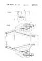
- FIG. 1is a sectional view of the coupling members in an assembled and locked condition
- FIG. 2is an enlarged fragmentary view of the seal means appearing in FIG. 1;
- FIG. 3is a sectional view of the coupling members in an assembled though unlocked condition
- FIG. 4is a front view of the assembled coupling members taken along line 4--4 of FIG. 3;
- FIG. 5is an enlarged fragmentary view of a cam member fastened to the housing and taken along line 5--5 of FIG. 3, and
- FIG. 6is a sectional view of the coupling members utilizing an alternate embodiment of the seal means.
- FIG. 1The preferred embodiment of the coupling apparatus for connecting together the ends of two pipes according to the present invention is illustrated generally in FIG. 1.
- coupling 2which includes a pair of coupling members 4 and 6, each of which is appropriately connected at one end thereof to the end of one of the pipes 8--8 as at 10.
- Coupling member 4has attached to the other end thereof an annular spherically-shaped ball-like enlarged portion 12 having axially forward and rearward sides 14 and 16, respectively.
- Coupling member 6on the other hand has attached to the other end thereof a socket or housing 18 having a spherically-shaped internal surface 20 for receiving the spherically-shaped forward side 14 in mating engagement therewith as shown in FIG. 1.
- this ball and socket arrangementenables the central axes of coupling members 4 and 6 to be inclined at an angle relative to each other to thereby connect similarly inclined pipe ends as illustrated by the intersecting axes in FIG. 1.
- forward and rearward sides 14 and 16will include those spherically-shaped surface portions of enlarged portion 12 which are respectively engaged with internal surface 20 and the cam members (yet to be described) irrespective of any relative misalignment between coupling members 4 and 6.
- a plurality of jaws or cam members 22are supported in circumferentially disposed relation about housing 18 as shown in FIG. 4 and movable radially inwards towards internal surface 20 between a retracted position (FIG. 3) in which housing 18 freely receives said spherically-shaped forward side 14 in mating engagement therewith, and an extended and locked position in which the ends 23 of cam members 22 engage said spherically-shaped rearward side 16 at a plurality of points circumferentially thereabout to urge enlarged portion 12 into positive contact with housing 18 to restrain coupling members 4 and 6 against relative axial and flexing movement to thus provide a rigid connection.
- each cam member 22is movable along a housing face 24 which tapers axially and radially inward towards internal surface 20 in the semblance of a frusto-cone and includes an elongated slot 26 (FIG. 5) in which is located a fastener 28 to support cam member 22 against housing face 24; cam member 22 being movable relative to fastener 28 between the retracted and extended positions aforesaid.
- Fastener 28in turn is threaded into housing 18 as at 30 and includes a head 32 which is larger in width than the width of slot 26 for obvious reasons.
- moving means 34includes a biasing surface 36 which constitutes an inner face of an axially movable annular ring 38 mounted onto housing 18 and having an opening 40 sufficiently large to accommodate enlarged portion 12; said biasing surface 36 being tapered radially inward away from housing face 24 in the semblance of a frusto-cone.
- Biasing surface 36in turn is engaged with a like tapered end 42 of each cam member 22 whereby when biasing surface 36 moves axially towards housing face 24 said cam members 22 will be moved radially inward from the retracted position of FIG. 3 to the extended position of FIG. 1.
- moving means 34includes in this embodiment of the invention a plurality of bolts 44 threaded at one end thereof into housing 18 as at 46 and extending at the other end thereof through a plurality of aligned holes 48 in annular ring 38. Nuts 49 are threaded onto bolts 44 to move annular ring 38 axially relative to housing 18 in an understood manner.
- housing 18is capable of freely receiving enlarged portion 12 through ring opening 40. Thereafter, nuts 48 are rotated to move ring 38 axially towards housing 18 with consequent radially inward movement of cam members 22 towards the extended position of FIG. 1. In the latter position it will be further understood that cam members 22 are also locked against movement by being wedged between housing face 24 and rearward side 16 to thereby provide a rigid connection.
- seal means 50disposed between enlarged portion 12 and housing 18 for providing a fluid seal therebetween.
- seal means 50includes an axially movable annular circumferentially continuous member 52 having a wedge-shaped portion 54 as best shown in FIG. 2 whereby when annular member 52 moves axially in one direction (in this case towards cam members 22) its wedge-shaped portion will become wedged between housing 18 as at 56 and enlarged portion 12 as at 58 to provide a fluid seal therebetween.
- annular member 52is formed of metal and includes an internal wall 60 which is spherically-shaped to correspond to the spherical contour of enlarged portion 12.
- annular member 52To procure axial movement of annular member 52 the invention visualizes urging means in the form of a plurality of pins 62 threaded into and through openings 64 in housing 18. Pins 62 in turn are engaged with a shoulder 66 of annular member 52 to selectively move the latter from the dotted line position (FIG. 2) to the solid line position shown in the same view in which said annular member 52 is wedged between housing 18 and enlarged portion 12 as aforesaid.
- FIGS. 1 and 3An alternate embodiment of the seal means as visualized herein is illustrated generally in FIGS. 1 and 3.
- an annular groove 68is provided in a wall of housing 18.
- annular elastomeric member 70Disposed snugly within groove 68 is an annular elastomeric member 70 which cooperates therewith to provide a sealed chamber 72, the latter communicating with a port 74 in housing 18 for introducing a pressurized fluid into chamber 72. Accordingly, it will be understood that when chamber 72 is pressurized elastomeric member 70 will be radially compressed from the disengaged position of FIG. 3 to the ball engaging position of FIG. 1 to effect a seal between enlarged portion 12 and housing 18.
- FIG. 6Another alternate embodiment of the seal means is shown in FIG. 6.
- annular elastomeric seal sections 76 and an annular rigid section 78are shown held in a recess 80 within housing 18.
- Rigid section 78is disposed to be engaged by cam members 22 as at 82 when the latter are in their extended position and thereby compress elastomeric seal sections 76 into sealing engagement with enlarged portion 12 as shown in FIG. 6.
- seal means housing 18includes an additional annular elastomeric seal section 84 disposed in axially spaced relation to the seal means to thereby define an annular testing chamber 86 therebetween as shown in FIGS. 1, 3 and 6.
- Conduit 88is in communication with chamber 86 to introduce pressurized fluid thereinto to thereby test the effectiveness of the seal means in the known manner.
- the inventionas visualized herein provides a ball and socket type coupling which is easy and quick to assemble to compensate for the rather limited working conditions that usually accompany pipe connections in a sub-sea environment. Moreover, this type coupling provides a rigid connection between the pipe ends while enabling them to be misaligned relative to each other if necessary.
Landscapes
- Engineering & Computer Science (AREA)
- General Engineering & Computer Science (AREA)
- Mechanical Engineering (AREA)
- Quick-Acting Or Multi-Walled Pipe Joints (AREA)
- Joints Allowing Movement (AREA)
- Flanged Joints, Insulating Joints, And Other Joints (AREA)
Abstract
Description
Claims (16)
Priority Applications (16)
| Application Number | Priority Date | Filing Date | Title |
|---|---|---|---|
| US05/602,439US4005881A (en) | 1975-08-06 | 1975-08-06 | Ring set ball coupling |
| NZ181378ANZ181378A (en) | 1975-08-06 | 1976-07-05 | Ball and socket pipe coupling |
| CA76256341ACA1048569A (en) | 1975-08-06 | 1976-07-06 | Ring set pipe coupling |
| IE1497/76AIE42896B1 (en) | 1975-08-06 | 1976-07-07 | Apparatus for connecting the ends of two pipes |
| AU16224/76AAU499319B2 (en) | 1975-08-06 | 1976-07-26 | Pipe coupling |
| GB31289/76AGB1489863A (en) | 1975-08-06 | 1976-07-27 | Apparatus for connecting the ends of two pipes |
| AR264162AAR211024A1 (en) | 1975-08-06 | 1976-07-30 | ROTULAR DEVICE FOR RIGID COUPLING OF TUBES. |
| BR7605021ABR7605021A (en) | 1975-08-06 | 1976-07-30 | APPLIANCE FOR CONNECTION OF PIPE END |
| NL7608601ANL7608601A (en) | 1975-08-06 | 1976-08-02 | PIPE COUPLING OF THE GLOBAL HINGE TYPE. |
| DK347176ADK347176A (en) | 1975-08-06 | 1976-08-02 | APPARATUS FOR CONNECTING TWO ROWS |
| FR7623718AFR2320489A1 (en) | 1975-08-06 | 1976-08-03 | COUPLING DEVICE FOR THE ENDS OF TWO DUCTS |
| IT50752/76AIT1073655B (en) | 1975-08-06 | 1976-08-04 | JUNCTION DEVICE FOR PIPES |
| JP51093540AJPS5245728A (en) | 1975-08-06 | 1976-08-05 | Pipe end jointing arrangement |
| DE2635269ADE2635269C3 (en) | 1975-08-06 | 1976-08-05 | Device for connecting the ends of two pipes |
| DE19767624660UDE7624660U1 (en) | 1975-08-06 | 1976-08-05 | DEVICE FOR CONNECTING THE ENDS OF TWO PIPES |
| MX165817AMX143223A (en) | 1975-08-06 | 1976-08-06 | IMPROVED DEVICE TO CONNECT THE END OF TWO TUBES |
Applications Claiming Priority (1)
| Application Number | Priority Date | Filing Date | Title |
|---|---|---|---|
| US05/602,439US4005881A (en) | 1975-08-06 | 1975-08-06 | Ring set ball coupling |
Publications (1)
| Publication Number | Publication Date |
|---|---|
| US4005881Atrue US4005881A (en) | 1977-02-01 |
Family
ID=24411365
Family Applications (1)
| Application Number | Title | Priority Date | Filing Date |
|---|---|---|---|
| US05/602,439Expired - LifetimeUS4005881A (en) | 1975-08-06 | 1975-08-06 | Ring set ball coupling |
Country Status (15)
| Country | Link |
|---|---|
| US (1) | US4005881A (en) |
| JP (1) | JPS5245728A (en) |
| AR (1) | AR211024A1 (en) |
| AU (1) | AU499319B2 (en) |
| BR (1) | BR7605021A (en) |
| CA (1) | CA1048569A (en) |
| DE (2) | DE2635269C3 (en) |
| DK (1) | DK347176A (en) |
| FR (1) | FR2320489A1 (en) |
| GB (1) | GB1489863A (en) |
| IE (1) | IE42896B1 (en) |
| IT (1) | IT1073655B (en) |
| MX (1) | MX143223A (en) |
| NL (1) | NL7608601A (en) |
| NZ (1) | NZ181378A (en) |
Cited By (18)
| Publication number | Priority date | Publication date | Assignee | Title |
|---|---|---|---|---|
| US4186950A (en)* | 1977-09-14 | 1980-02-05 | Comex Marine Services, Inc. | Coupling apparatus |
| US4676531A (en)* | 1985-04-15 | 1987-06-30 | Martin Charles F | Apparatus for clamping and sealing the outer surface of a pipe and fittings for pipe connection |
| FR2597953A1 (en)* | 1986-04-23 | 1987-10-30 | Andre Hermand | Pneumatic sampling device, especially for granular or powdered substances |
| US4778203A (en)* | 1982-03-22 | 1988-10-18 | Proprietary Technology, Inc. | Swivelable quick connector for high temperature connection |
| US4913471A (en)* | 1987-11-10 | 1990-04-03 | Huneke Gerald L | Swivel joint |
| US5149147A (en)* | 1991-04-18 | 1992-09-22 | General Electric Company | Conduit coupling for high temperature, high pressure applications |
| US5868524A (en)* | 1996-07-25 | 1999-02-09 | Martin; Charles F. | Clamp system and method for connecting tubular bodies together |
| US6158781A (en)* | 1998-05-18 | 2000-12-12 | Taper-Lok | Pipeline swivel coupling |
| US6305720B1 (en)* | 1999-03-18 | 2001-10-23 | Big Inch Marine Systems | Remote articulated connector |
| US20040245777A1 (en)* | 2003-06-06 | 2004-12-09 | Smail Vila | Flexible coupling for gas conduits |
| US20070246620A1 (en)* | 2004-10-26 | 2007-10-25 | Fugro Engineers B.V. | Movable supporting construction |
| US7784835B1 (en)* | 2006-12-05 | 2010-08-31 | Keays Steven J | Pipe connecting member |
| US20120193906A1 (en)* | 2011-02-02 | 2012-08-02 | David James Alexander | Riser bending relief joint |
| KR101536604B1 (en)* | 2014-01-27 | 2015-07-15 | 주식회사 와이티티월드 | Ball joint apparatus for piping |
| KR101536605B1 (en)* | 2014-01-27 | 2015-07-15 | 주식회사 와이티티월드 | Ball joint apparatus for piping |
| WO2017100524A1 (en)* | 2015-12-09 | 2017-06-15 | National Oilwell Varco, L.P. | Articulating joint and system for conveying fluid flow |
| US10132437B2 (en)* | 2014-12-05 | 2018-11-20 | Oetiker Ny, Inc. | Fluid connector with a swivel body |
| WO2019064089A1 (en)* | 2017-09-30 | 2019-04-04 | Earat Somanadhan Nikhil | Underground pipe couplings for emergency repair during pipe breakage |
Families Citing this family (4)
| Publication number | Priority date | Publication date | Assignee | Title |
|---|---|---|---|---|
| JPS55173787U (en)* | 1979-05-31 | 1980-12-12 | ||
| DE4219442C1 (en)* | 1992-06-13 | 1993-06-09 | Manfred 6610 Lebach De Klauck | Releasable pressure-tight coupler for high-pressure pipelines - is sealed by rings of different sizes in grooves of curved and plane faces of insert |
| DE102016011983A1 (en)* | 2016-10-10 | 2018-04-12 | Mann + Hummel Gmbh | Coupling arrangement for pipelines |
| DE102018131675A1 (en)* | 2018-12-11 | 2020-06-18 | Bayerische Motoren Werke Aktiengesellschaft | Gas-tight joint connection with a spherical cap |
Citations (8)
| Publication number | Priority date | Publication date | Assignee | Title |
|---|---|---|---|---|
| US908414A (en)* | 1904-10-06 | 1908-12-29 | American Locomotive Co | Flexible ball-joint. |
| US1193483A (en)* | 1916-08-01 | Levin s | ||
| DE858170C (en)* | 1950-12-28 | 1952-12-04 | Wilhelm Dr-Ing Geldbach | Quick-release pipe coupling, preferably ball couplings in compressed air lines |
| US2714021A (en)* | 1950-03-21 | 1955-07-26 | So Called Tecalemit Sa Soc | Pressure-lubricating devices |
| US3134613A (en)* | 1961-03-31 | 1964-05-26 | Regan Forge & Eng Co | Quick-connect fitting for oil well tubing |
| US3185504A (en)* | 1961-07-19 | 1965-05-25 | Perrot Regnerbau G M B H & Co | Coupling arrangement |
| US3873138A (en)* | 1972-10-19 | 1975-03-25 | Caterpillar Tractor Co | Quick disconnect sealed coupling |
| US3874706A (en)* | 1971-10-15 | 1975-04-01 | Hydrotech Int Inc | Fluid actuated pipe connection |
Family Cites Families (3)
| Publication number | Priority date | Publication date | Assignee | Title |
|---|---|---|---|---|
| US3450421A (en)* | 1966-06-20 | 1969-06-17 | Gray Tool Co | Ball connector |
| US3433504A (en)* | 1966-07-05 | 1969-03-18 | Ventura Tool Co | Flexible connectors |
| US3695633A (en)* | 1970-03-19 | 1972-10-03 | Vetco Offshore Ind Inc | Remotely controlled hydraulically operated connectible and disconnectible flexible joint |
- 1975
- 1975-08-06USUS05/602,439patent/US4005881A/ennot_activeExpired - Lifetime
- 1976
- 1976-07-05NZNZ181378Apatent/NZ181378A/enunknown
- 1976-07-06CACA76256341Apatent/CA1048569A/ennot_activeExpired
- 1976-07-07IEIE1497/76Apatent/IE42896B1/enunknown
- 1976-07-26AUAU16224/76Apatent/AU499319B2/ennot_activeExpired
- 1976-07-27GBGB31289/76Apatent/GB1489863A/ennot_activeExpired
- 1976-07-30ARAR264162Apatent/AR211024A1/enactive
- 1976-07-30BRBR7605021Apatent/BR7605021A/enunknown
- 1976-08-02NLNL7608601Apatent/NL7608601A/ennot_activeApplication Discontinuation
- 1976-08-02DKDK347176Apatent/DK347176A/ennot_activeApplication Discontinuation
- 1976-08-03FRFR7623718Apatent/FR2320489A1/enactiveGranted
- 1976-08-04ITIT50752/76Apatent/IT1073655B/enactive
- 1976-08-05DEDE2635269Apatent/DE2635269C3/ennot_activeExpired
- 1976-08-05DEDE19767624660Upatent/DE7624660U1/ennot_activeExpired
- 1976-08-05JPJP51093540Apatent/JPS5245728A/enactivePending
- 1976-08-06MXMX165817Apatent/MX143223A/enunknown
Patent Citations (8)
| Publication number | Priority date | Publication date | Assignee | Title |
|---|---|---|---|---|
| US1193483A (en)* | 1916-08-01 | Levin s | ||
| US908414A (en)* | 1904-10-06 | 1908-12-29 | American Locomotive Co | Flexible ball-joint. |
| US2714021A (en)* | 1950-03-21 | 1955-07-26 | So Called Tecalemit Sa Soc | Pressure-lubricating devices |
| DE858170C (en)* | 1950-12-28 | 1952-12-04 | Wilhelm Dr-Ing Geldbach | Quick-release pipe coupling, preferably ball couplings in compressed air lines |
| US3134613A (en)* | 1961-03-31 | 1964-05-26 | Regan Forge & Eng Co | Quick-connect fitting for oil well tubing |
| US3185504A (en)* | 1961-07-19 | 1965-05-25 | Perrot Regnerbau G M B H & Co | Coupling arrangement |
| US3874706A (en)* | 1971-10-15 | 1975-04-01 | Hydrotech Int Inc | Fluid actuated pipe connection |
| US3873138A (en)* | 1972-10-19 | 1975-03-25 | Caterpillar Tractor Co | Quick disconnect sealed coupling |
Cited By (24)
| Publication number | Priority date | Publication date | Assignee | Title |
|---|---|---|---|---|
| US4186950A (en)* | 1977-09-14 | 1980-02-05 | Comex Marine Services, Inc. | Coupling apparatus |
| US4778203A (en)* | 1982-03-22 | 1988-10-18 | Proprietary Technology, Inc. | Swivelable quick connector for high temperature connection |
| US4676531A (en)* | 1985-04-15 | 1987-06-30 | Martin Charles F | Apparatus for clamping and sealing the outer surface of a pipe and fittings for pipe connection |
| FR2597953A1 (en)* | 1986-04-23 | 1987-10-30 | Andre Hermand | Pneumatic sampling device, especially for granular or powdered substances |
| US4913471A (en)* | 1987-11-10 | 1990-04-03 | Huneke Gerald L | Swivel joint |
| US5149147A (en)* | 1991-04-18 | 1992-09-22 | General Electric Company | Conduit coupling for high temperature, high pressure applications |
| US5868524A (en)* | 1996-07-25 | 1999-02-09 | Martin; Charles F. | Clamp system and method for connecting tubular bodies together |
| US6158781A (en)* | 1998-05-18 | 2000-12-12 | Taper-Lok | Pipeline swivel coupling |
| US6305720B1 (en)* | 1999-03-18 | 2001-10-23 | Big Inch Marine Systems | Remote articulated connector |
| US6698800B2 (en) | 1999-03-18 | 2004-03-02 | Oil States Industries, Inc. | Remote connector including support structure |
| US20040245777A1 (en)* | 2003-06-06 | 2004-12-09 | Smail Vila | Flexible coupling for gas conduits |
| US6880863B2 (en) | 2003-06-06 | 2005-04-19 | Delaware Capital Formation, Inc. | Flexible coupling for gas conduits |
| US20070246620A1 (en)* | 2004-10-26 | 2007-10-25 | Fugro Engineers B.V. | Movable supporting construction |
| US8418986B2 (en)* | 2004-10-26 | 2013-04-16 | Fugro Engineers B.V. | Movable supporting construction |
| US7784835B1 (en)* | 2006-12-05 | 2010-08-31 | Keays Steven J | Pipe connecting member |
| US20120193906A1 (en)* | 2011-02-02 | 2012-08-02 | David James Alexander | Riser bending relief joint |
| US8720953B2 (en)* | 2011-02-02 | 2014-05-13 | Vetco Gray Inc. | Riser bending relief joint |
| KR101536604B1 (en)* | 2014-01-27 | 2015-07-15 | 주식회사 와이티티월드 | Ball joint apparatus for piping |
| KR101536605B1 (en)* | 2014-01-27 | 2015-07-15 | 주식회사 와이티티월드 | Ball joint apparatus for piping |
| US10132437B2 (en)* | 2014-12-05 | 2018-11-20 | Oetiker Ny, Inc. | Fluid connector with a swivel body |
| WO2017100524A1 (en)* | 2015-12-09 | 2017-06-15 | National Oilwell Varco, L.P. | Articulating joint and system for conveying fluid flow |
| US10704717B2 (en) | 2015-12-09 | 2020-07-07 | National Oilwell Varco, L.P. | Articulating joint and system for conveying fluid flow |
| WO2019064089A1 (en)* | 2017-09-30 | 2019-04-04 | Earat Somanadhan Nikhil | Underground pipe couplings for emergency repair during pipe breakage |
| US11473706B2 (en) | 2017-09-30 | 2022-10-18 | Nikhil Earat Somanadhan | Underground pipe couplings for emergency repair during pipe breakage |
Also Published As
| Publication number | Publication date |
|---|---|
| AR211024A1 (en) | 1977-10-01 |
| CA1048569A (en) | 1979-02-13 |
| AU499319B2 (en) | 1979-04-12 |
| IE42896B1 (en) | 1980-11-05 |
| DK347176A (en) | 1977-02-07 |
| BR7605021A (en) | 1977-08-09 |
| DE2635269A1 (en) | 1977-02-17 |
| AU1622476A (en) | 1978-02-02 |
| DE2635269C3 (en) | 1979-10-25 |
| DE2635269B2 (en) | 1979-03-08 |
| FR2320489B1 (en) | 1979-06-22 |
| IT1073655B (en) | 1985-04-17 |
| DE7624660U1 (en) | 1980-04-10 |
| NL7608601A (en) | 1977-02-08 |
| JPS5245728A (en) | 1977-04-11 |
| NZ181378A (en) | 1978-07-28 |
| MX143223A (en) | 1981-04-03 |
| IE42896L (en) | 1977-02-06 |
| GB1489863A (en) | 1977-10-26 |
| FR2320489A1 (en) | 1977-03-04 |
Similar Documents
| Publication | Publication Date | Title |
|---|---|---|
| US4005881A (en) | Ring set ball coupling | |
| US3997197A (en) | Ball and socket pipe coupling | |
| US2784987A (en) | Pipe coupling with detent means | |
| US3260539A (en) | Coupling for fluid conduits | |
| US4639019A (en) | Luer connection | |
| US4180285A (en) | Articulated ball connector for use with pipeline | |
| US4045054A (en) | Apparatus for rigidly interconnecting misaligned pipe ends | |
| US3348575A (en) | Hydraulically actuatable fluid coupling | |
| US3718350A (en) | Snap ring coupling | |
| US4040650A (en) | Articulate conduit connector | |
| EP3798492B1 (en) | Quick-insertion coupling joint | |
| US4372584A (en) | Coupling for coupling tubular elements | |
| US6158781A (en) | Pipeline swivel coupling | |
| US4213482A (en) | Hydraulic coupler | |
| KR880012938A (en) | Straight Connection Hydraulic Quick Coupler | |
| US4253683A (en) | Safety-bleed-stop hose coupling | |
| US3138393A (en) | Coupling for substantially axially fixed conduits | |
| US2591531A (en) | Pipe coupling | |
| US2744771A (en) | Pipe coupling ring with locking means | |
| EP0727026B1 (en) | Pipe connector | |
| US6471250B2 (en) | Junction plate assembly for undersea hydraulic couplings | |
| GB1293283A (en) | Coupling device for coupling together two conduits | |
| US4186950A (en) | Coupling apparatus | |
| US3902747A (en) | Coupling and coupling system for conduits | |
| US7219932B2 (en) | Junction plate for subsea hydraulic couplings |
Legal Events
| Date | Code | Title | Description |
|---|---|---|---|
| AS | Assignment | Owner name:HYDROTECH INTERNATIONAL, INC. Free format text:ASSIGNMENT OF ASSIGNORS INTEREST.;ASSIGNORS:FIRST NATIONAL BANK OF CHICAGO;TEXAS COMMERCE BANK NATIONAL ASSOCIATION;REEL/FRAME:003928/0033 Effective date:19801024 Owner name:HYDROTECH INTERNATIONAL, INC., TEXAS Free format text:ASSIGNMENT OF ASSIGNORS INTEREST;ASSIGNORS:FIRST NATIONAL BANK OF CHICAGO;TEXAS COMMERCE BANK NATIONAL ASSOCIATION;REEL/FRAME:003928/0033 Effective date:19801024 | |
| AS | Assignment | Owner name:HYDROTECH-HUGHES, INC. Free format text:CHANGE OF NAME;ASSIGNOR:HUGHES UNDERSEA COUPLINGS, INCORPORATED;REEL/FRAME:004021/0868 Effective date:19820611 Owner name:HUGHES TOOL COMPANY Free format text:MERGER;ASSIGNOR:HYDROTECH-HUGHES, INC.;REEL/FRAME:004021/0860 Effective date:19811214 | |
| AS | Assignment | Owner name:CAL DRIVE INTERNATIONAL, INC., 115 INDUSTRIAL PARK Free format text:ASSIGNMENT OF ASSIGNORS INTEREST. SUBJECT TO CONDITIONS RECITED;ASSIGNOR:HUGHES TOOL COMPANY;REEL/FRAME:004348/0009 | |
| AS | Assignment | Owner name:HYDROTECH INTERNATIONAL, INC., 11800 CHARLES ST., Free format text:RELEASED BY SECURED PARTY;ASSIGNOR:CITIBANK (INTERNATIONAL-HOUSTON) A CORP.;REEL/FRAME:004372/0116 Effective date:19850225 | |
| AS | Assignment | Owner name:HYDROTECH SYSTEMS INC., 4959 WEST 34TH STREET, SUI Free format text:ASSIGNMENT OF ASSIGNORS INTEREST.;ASSIGNOR:CAL DIVE INTERNATIONAL, INC;REEL/FRAME:004404/0162 Effective date:19850102 | |
| AS | Assignment | Owner name:HSI ACQUISITIONS, INC. Free format text:ASSIGNMENT OF ASSIGNORS INTEREST.;ASSIGNOR:HYDROTECH SYSTEMS, INC., A MN CORP.;REEL/FRAME:005075/0578 Effective date:19880812 | |
| AS | Assignment | Owner name:BAKER HUGHES INCORPORATED, A CORP. OF DE, TEXAS Free format text:SECURITY INTEREST;ASSIGNOR:HSI ACQUISITIONS, INC.;REEL/FRAME:005199/0337 Effective date:19891212 |