US4004710A - Container and closure therefor - Google Patents
Container and closure thereforDownload PDFInfo
- Publication number
- US4004710A US4004710AUS05/645,891US64589175AUS4004710AUS 4004710 AUS4004710 AUS 4004710AUS 64589175 AUS64589175 AUS 64589175AUS 4004710 AUS4004710 AUS 4004710A
- Authority
- US
- United States
- Prior art keywords
- wall
- lip
- container
- rim
- closure
- Prior art date
- Legal status (The legal status is an assumption and is not a legal conclusion. Google has not performed a legal analysis and makes no representation as to the accuracy of the status listed.)
- Expired - Lifetime
Links
- 238000007789sealingMethods0.000claimsabstractdescription28
- 239000000463materialSubstances0.000claimsabstractdescription17
- 239000004033plasticSubstances0.000claimsabstractdescription13
- 229920003023plasticPolymers0.000claimsabstractdescription13
- 239000011324beadSubstances0.000claimsdescription24
- 238000003780insertionMethods0.000claimsdescription2
- 230000037431insertionEffects0.000claimsdescription2
- 230000002093peripheral effectEffects0.000abstractdescription7
- 239000012530fluidSubstances0.000abstractdescription3
- 230000000295complement effectEffects0.000abstract1
- 239000003973paintSubstances0.000description10
- 238000004873anchoringMethods0.000description7
- 238000010276constructionMethods0.000description5
- 238000004519manufacturing processMethods0.000description3
- 239000002184metalSubstances0.000description3
- 238000005260corrosionMethods0.000description2
- 230000007797corrosionEffects0.000description2
- 230000001419dependent effectEffects0.000description2
- 239000004816latexSubstances0.000description2
- 229920000126latexPolymers0.000description2
- 238000000465mouldingMethods0.000description2
- -1polypropylenePolymers0.000description2
- 230000000750progressive effectEffects0.000description2
- 239000004698PolyethyleneSubstances0.000description1
- 239000004743PolypropyleneSubstances0.000description1
- 229910000831SteelInorganic materials0.000description1
- 230000015572biosynthetic processEffects0.000description1
- 238000001035dryingMethods0.000description1
- 230000000694effectsEffects0.000description1
- 229920001903high density polyethylenePolymers0.000description1
- 239000004700high-density polyethyleneSubstances0.000description1
- 238000001746injection mouldingMethods0.000description1
- 230000003993interactionEffects0.000description1
- 239000007788liquidSubstances0.000description1
- 238000000034methodMethods0.000description1
- 238000012986modificationMethods0.000description1
- 230000004048modificationEffects0.000description1
- 238000004806packaging method and processMethods0.000description1
- 229920000573polyethylenePolymers0.000description1
- 229920001155polypropylenePolymers0.000description1
- 238000003825pressingMethods0.000description1
- 238000009877renderingMethods0.000description1
- 239000010959steelSubstances0.000description1
- XLYOFNOQVPJJNP-UHFFFAOYSA-NwaterSubstancesOXLYOFNOQVPJJNP-UHFFFAOYSA-N0.000description1
Images

Classifications
- B—PERFORMING OPERATIONS; TRANSPORTING
- B65—CONVEYING; PACKING; STORING; HANDLING THIN OR FILAMENTARY MATERIAL
- B65D—CONTAINERS FOR STORAGE OR TRANSPORT OF ARTICLES OR MATERIALS, e.g. BAGS, BARRELS, BOTTLES, BOXES, CANS, CARTONS, CRATES, DRUMS, JARS, TANKS, HOPPERS, FORWARDING CONTAINERS; ACCESSORIES, CLOSURES, OR FITTINGS THEREFOR; PACKAGING ELEMENTS; PACKAGES
- B65D21/00—Nestable, stackable or joinable containers; Containers of variable capacity
- B65D21/02—Containers specially shaped, or provided with fittings or attachments, to facilitate nesting, stacking, or joining together
- B65D21/0209—Containers specially shaped, or provided with fittings or attachments, to facilitate nesting, stacking, or joining together stackable or joined together one-upon-the-other in the upright or upside-down position
- B65D21/0217—Containers with a closure presenting stacking elements
- B65D21/0222—Containers with a closure presenting stacking elements the closure and the bottom presenting co-operating peripheral ribs and grooves
- B—PERFORMING OPERATIONS; TRANSPORTING
- B65—CONVEYING; PACKING; STORING; HANDLING THIN OR FILAMENTARY MATERIAL
- B65D—CONTAINERS FOR STORAGE OR TRANSPORT OF ARTICLES OR MATERIALS, e.g. BAGS, BARRELS, BOTTLES, BOXES, CANS, CARTONS, CRATES, DRUMS, JARS, TANKS, HOPPERS, FORWARDING CONTAINERS; ACCESSORIES, CLOSURES, OR FITTINGS THEREFOR; PACKAGING ELEMENTS; PACKAGES
- B65D21/00—Nestable, stackable or joinable containers; Containers of variable capacity
- B65D21/02—Containers specially shaped, or provided with fittings or attachments, to facilitate nesting, stacking, or joining together
- B65D21/0233—Nestable containers
- B—PERFORMING OPERATIONS; TRANSPORTING
- B65—CONVEYING; PACKING; STORING; HANDLING THIN OR FILAMENTARY MATERIAL
- B65D—CONTAINERS FOR STORAGE OR TRANSPORT OF ARTICLES OR MATERIALS, e.g. BAGS, BARRELS, BOTTLES, BOXES, CANS, CARTONS, CRATES, DRUMS, JARS, TANKS, HOPPERS, FORWARDING CONTAINERS; ACCESSORIES, CLOSURES, OR FITTINGS THEREFOR; PACKAGING ELEMENTS; PACKAGES
- B65D25/00—Details of other kinds or types of rigid or semi-rigid containers
- B65D25/28—Handles
- B65D25/32—Bail handles, i.e. pivoted rigid handles of generally semi-circular shape with pivot points on two opposed sides or wall parts of the conainter
- B—PERFORMING OPERATIONS; TRANSPORTING
- B65—CONVEYING; PACKING; STORING; HANDLING THIN OR FILAMENTARY MATERIAL
- B65D—CONTAINERS FOR STORAGE OR TRANSPORT OF ARTICLES OR MATERIALS, e.g. BAGS, BARRELS, BOTTLES, BOXES, CANS, CARTONS, CRATES, DRUMS, JARS, TANKS, HOPPERS, FORWARDING CONTAINERS; ACCESSORIES, CLOSURES, OR FITTINGS THEREFOR; PACKAGING ELEMENTS; PACKAGES
- B65D43/00—Lids or covers for rigid or semi-rigid containers
- B65D43/02—Removable lids or covers
- B65D43/0202—Removable lids or covers without integral tamper element
- B65D43/0204—Removable lids or covers without integral tamper element secured by snapping over beads or projections
- B65D43/0212—Removable lids or covers without integral tamper element secured by snapping over beads or projections only on the outside, or a part turned to the outside, of the mouth
- B—PERFORMING OPERATIONS; TRANSPORTING
- B65—CONVEYING; PACKING; STORING; HANDLING THIN OR FILAMENTARY MATERIAL
- B65D—CONTAINERS FOR STORAGE OR TRANSPORT OF ARTICLES OR MATERIALS, e.g. BAGS, BARRELS, BOTTLES, BOXES, CANS, CARTONS, CRATES, DRUMS, JARS, TANKS, HOPPERS, FORWARDING CONTAINERS; ACCESSORIES, CLOSURES, OR FITTINGS THEREFOR; PACKAGING ELEMENTS; PACKAGES
- B65D2543/00—Lids or covers essentially for box-like containers
- B65D2543/00009—Details of lids or covers for rigid or semi-rigid containers
- B65D2543/00018—Overall construction of the lid
- B65D2543/00064—Shape of the outer periphery
- B65D2543/00074—Shape of the outer periphery curved
- B65D2543/00092—Shape of the outer periphery curved circular
- B—PERFORMING OPERATIONS; TRANSPORTING
- B65—CONVEYING; PACKING; STORING; HANDLING THIN OR FILAMENTARY MATERIAL
- B65D—CONTAINERS FOR STORAGE OR TRANSPORT OF ARTICLES OR MATERIALS, e.g. BAGS, BARRELS, BOTTLES, BOXES, CANS, CARTONS, CRATES, DRUMS, JARS, TANKS, HOPPERS, FORWARDING CONTAINERS; ACCESSORIES, CLOSURES, OR FITTINGS THEREFOR; PACKAGING ELEMENTS; PACKAGES
- B65D2543/00—Lids or covers essentially for box-like containers
- B65D2543/00009—Details of lids or covers for rigid or semi-rigid containers
- B65D2543/00018—Overall construction of the lid
- B65D2543/00259—Materials used
- B65D2543/00296—Plastic
- B—PERFORMING OPERATIONS; TRANSPORTING
- B65—CONVEYING; PACKING; STORING; HANDLING THIN OR FILAMENTARY MATERIAL
- B65D—CONTAINERS FOR STORAGE OR TRANSPORT OF ARTICLES OR MATERIALS, e.g. BAGS, BARRELS, BOTTLES, BOXES, CANS, CARTONS, CRATES, DRUMS, JARS, TANKS, HOPPERS, FORWARDING CONTAINERS; ACCESSORIES, CLOSURES, OR FITTINGS THEREFOR; PACKAGING ELEMENTS; PACKAGES
- B65D2543/00—Lids or covers essentially for box-like containers
- B65D2543/00009—Details of lids or covers for rigid or semi-rigid containers
- B65D2543/00342—Central part of the lid
- B65D2543/00398—Reinforcing ribs in the central part of the closure
- B65D2543/00416—Reinforcing ribs in the central part of the closure circular
- B—PERFORMING OPERATIONS; TRANSPORTING
- B65—CONVEYING; PACKING; STORING; HANDLING THIN OR FILAMENTARY MATERIAL
- B65D—CONTAINERS FOR STORAGE OR TRANSPORT OF ARTICLES OR MATERIALS, e.g. BAGS, BARRELS, BOTTLES, BOXES, CANS, CARTONS, CRATES, DRUMS, JARS, TANKS, HOPPERS, FORWARDING CONTAINERS; ACCESSORIES, CLOSURES, OR FITTINGS THEREFOR; PACKAGING ELEMENTS; PACKAGES
- B65D2543/00—Lids or covers essentially for box-like containers
- B65D2543/00009—Details of lids or covers for rigid or semi-rigid containers
- B65D2543/00444—Contact between the container and the lid
- B65D2543/00481—Contact between the container and the lid on the inside or the outside of the container
- B65D2543/0049—Contact between the container and the lid on the inside or the outside of the container on the inside, or a part turned to the inside of the mouth of the container
- B65D2543/005—Contact between the container and the lid on the inside or the outside of the container on the inside, or a part turned to the inside of the mouth of the container both cup and skirt
- B—PERFORMING OPERATIONS; TRANSPORTING
- B65—CONVEYING; PACKING; STORING; HANDLING THIN OR FILAMENTARY MATERIAL
- B65D—CONTAINERS FOR STORAGE OR TRANSPORT OF ARTICLES OR MATERIALS, e.g. BAGS, BARRELS, BOTTLES, BOXES, CANS, CARTONS, CRATES, DRUMS, JARS, TANKS, HOPPERS, FORWARDING CONTAINERS; ACCESSORIES, CLOSURES, OR FITTINGS THEREFOR; PACKAGING ELEMENTS; PACKAGES
- B65D2543/00—Lids or covers essentially for box-like containers
- B65D2543/00009—Details of lids or covers for rigid or semi-rigid containers
- B65D2543/00444—Contact between the container and the lid
- B65D2543/00481—Contact between the container and the lid on the inside or the outside of the container
- B65D2543/00537—Contact between the container and the lid on the inside or the outside of the container on the outside, or a part turned to the outside of the mouth of the container
- B—PERFORMING OPERATIONS; TRANSPORTING
- B65—CONVEYING; PACKING; STORING; HANDLING THIN OR FILAMENTARY MATERIAL
- B65D—CONTAINERS FOR STORAGE OR TRANSPORT OF ARTICLES OR MATERIALS, e.g. BAGS, BARRELS, BOTTLES, BOXES, CANS, CARTONS, CRATES, DRUMS, JARS, TANKS, HOPPERS, FORWARDING CONTAINERS; ACCESSORIES, CLOSURES, OR FITTINGS THEREFOR; PACKAGING ELEMENTS; PACKAGES
- B65D2543/00—Lids or covers essentially for box-like containers
- B65D2543/00009—Details of lids or covers for rigid or semi-rigid containers
- B65D2543/00444—Contact between the container and the lid
- B65D2543/00481—Contact between the container and the lid on the inside or the outside of the container
- B65D2543/00555—Contact between the container and the lid on the inside or the outside of the container on both the inside and the outside
- B—PERFORMING OPERATIONS; TRANSPORTING
- B65—CONVEYING; PACKING; STORING; HANDLING THIN OR FILAMENTARY MATERIAL
- B65D—CONTAINERS FOR STORAGE OR TRANSPORT OF ARTICLES OR MATERIALS, e.g. BAGS, BARRELS, BOTTLES, BOXES, CANS, CARTONS, CRATES, DRUMS, JARS, TANKS, HOPPERS, FORWARDING CONTAINERS; ACCESSORIES, CLOSURES, OR FITTINGS THEREFOR; PACKAGING ELEMENTS; PACKAGES
- B65D2543/00—Lids or covers essentially for box-like containers
- B65D2543/00009—Details of lids or covers for rigid or semi-rigid containers
- B65D2543/00444—Contact between the container and the lid
- B65D2543/00592—Snapping means
- B65D2543/00601—Snapping means on the container
- B65D2543/00611—Profiles
- B65D2543/00629—Massive bead
- B—PERFORMING OPERATIONS; TRANSPORTING
- B65—CONVEYING; PACKING; STORING; HANDLING THIN OR FILAMENTARY MATERIAL
- B65D—CONTAINERS FOR STORAGE OR TRANSPORT OF ARTICLES OR MATERIALS, e.g. BAGS, BARRELS, BOTTLES, BOXES, CANS, CARTONS, CRATES, DRUMS, JARS, TANKS, HOPPERS, FORWARDING CONTAINERS; ACCESSORIES, CLOSURES, OR FITTINGS THEREFOR; PACKAGING ELEMENTS; PACKAGES
- B65D2543/00—Lids or covers essentially for box-like containers
- B65D2543/00009—Details of lids or covers for rigid or semi-rigid containers
- B65D2543/00444—Contact between the container and the lid
- B65D2543/00592—Snapping means
- B65D2543/00601—Snapping means on the container
- B65D2543/00675—Periphery concerned
- B65D2543/00685—Totality
- B—PERFORMING OPERATIONS; TRANSPORTING
- B65—CONVEYING; PACKING; STORING; HANDLING THIN OR FILAMENTARY MATERIAL
- B65D—CONTAINERS FOR STORAGE OR TRANSPORT OF ARTICLES OR MATERIALS, e.g. BAGS, BARRELS, BOTTLES, BOXES, CANS, CARTONS, CRATES, DRUMS, JARS, TANKS, HOPPERS, FORWARDING CONTAINERS; ACCESSORIES, CLOSURES, OR FITTINGS THEREFOR; PACKAGING ELEMENTS; PACKAGES
- B65D2543/00—Lids or covers essentially for box-like containers
- B65D2543/00009—Details of lids or covers for rigid or semi-rigid containers
- B65D2543/00444—Contact between the container and the lid
- B65D2543/00592—Snapping means
- B65D2543/00712—Snapping means on the lid
- B65D2543/00722—Profiles
- B65D2543/0074—Massive bead
- B—PERFORMING OPERATIONS; TRANSPORTING
- B65—CONVEYING; PACKING; STORING; HANDLING THIN OR FILAMENTARY MATERIAL
- B65D—CONTAINERS FOR STORAGE OR TRANSPORT OF ARTICLES OR MATERIALS, e.g. BAGS, BARRELS, BOTTLES, BOXES, CANS, CARTONS, CRATES, DRUMS, JARS, TANKS, HOPPERS, FORWARDING CONTAINERS; ACCESSORIES, CLOSURES, OR FITTINGS THEREFOR; PACKAGING ELEMENTS; PACKAGES
- B65D2543/00—Lids or covers essentially for box-like containers
- B65D2543/00009—Details of lids or covers for rigid or semi-rigid containers
- B65D2543/00444—Contact between the container and the lid
- B65D2543/00592—Snapping means
- B65D2543/00712—Snapping means on the lid
- B65D2543/00787—Periphery concerned
- B65D2543/00796—Totality
Definitions
- This inventionrelates to containers and closures therefor and more particularly to containers manufactured of plastics materials and adapted to hold fluids such as latex-based paints and the like.
- Painta material which requires a strong light-weight container, traditionally is packaged in cylindrical drum-type cans fabricated from sheet metal - usually tin-plated steel. Due to the nature of paint, it is necessary to have a completely fluid-tight seal between container and lid otherwise drying out of the material would occur thereby rendering it useless.
- a simple circular lid having a formed peripheral edge such as to provide an interference fit within the mouth of the containerprovides an adequate seal.
- Metal paint container bodiesagain for reasons of ease of production and cost, are usually cylindrical in shape so that when empty they cannot be “nested". Packaging of empty containers, therefore, is bulky and inconvenient from a handling, storing, transportation and expense point of view.
- An object of the present inventionis to provide a closure of plastics material for a container body which may be removed without damaging the closure thereby enabling it to be re-used.
- Another objectis to provide a container of plastics material which avoids the need for the use of a seal which is additional to the container body and closure.
- a plastics closure for a container bodyhaving a cover portion surrounded by an annular U-shaped rim, the rim comprising a radially inner axial wall, a spaced radially outer axial wall and a base interconnecting said walls which define between them an axially facing recess for receiving a lip of the body, the outer wall incorporating a radially inwardly projecting bead spaced from the base and a skirt which flares outwardly from the outer wall on the side of the bead remote from the base, and the outer wall being resiliently flexible outwardly to enable snap engagement of the closure with and its release from the container lip.
- the beadis a relatively stiff portion of the outer wall which applies an annular constricting force to hold the wall in its normal position.
- the flared skirtacts as a lever which when urged radially outwards and upwards at a specific circumferential point, flexes the outer wall at that point resiliently to stretch the bead to allow it to commence movement around the lip in a closure releasing direction.
- Outward levering of the skirt circumferentially in a progressive manner from said specific pointstretches the bead in corresponding fashion so as completely to unseat it from the lip.
- the beadserves not only as a constrictive force but because it is a region of relatively greater stiffness than the remainder of the wall, the wall tends to flex at a bend position towards the base upon the application of a radially outwards force upon the skirt so that the bead is pivoted from the bend position.
- the flared skirttends towards an axially straight line relationship with the remainder of the outer wall whereby when a radially outwards force is applied to the skirt, there is a large component of force also applied radially outwards to the remainder of the wall so as to stretch it.
- the skirtmay have a thickness no greater than the remainder of the wall, apart from at the bead, while being sufficiently stiff to cause bead removal without any undue flexing of the skirt itself relative to the wall towards the base.
- the angle of the skirtis between 35° and 45° to the axial direction in its normal and unflexed state with the preferred angle being 40°.
- a containercomprises a container body and a closure both being of plastics material, the body having an annular wall defining an opening and a lip around the opening, the lip having a sealing region surrounding the opening and a radially outwardly directed shoulder spaced axially along the wall from the sealing region, and the closure having a cover portion surrounded by a U-shaped rim, the rim comprising a radially inner axial wall, a spaced radially outer axial wall and a base interconnecting said walls which define between them an axially facing recess of the rim for insertion of the lip between the walls, the rim also including a sealing region in an area of the inner wall and base, one sealing region being in compressively loaded and tangential engagement with the other region along a single annular line when the lip is received within the rim, and the outer wall incorporating a radially inwardly projecting bead to coact with the shoulder to urge the sealing regions into said engagement, the outer wall being resiliently flexible
- the container body and closureprovide a cheap, easily manufactured, container which, when the two parts are assembled together is fluid tight and the closure will not easily detach itself from the container body under loads applied to it in an accidental manner because of the circumferentially applied constrictive force by the bead.
- the sealing regionsprovide an efficient seal as the full compressive loading acting between the sealing regions acts at the single annular line of contact thus creating maximum pressure conditions to make and retain a sealed condition.
- the two sealing regionsmay be surfaces which are of such relative shapes as to provide single annular line of contact when they are engaged.
- the rim sealing regionis an annular splayed surface extending radially outwards towards the base and the lip sealing region is a convex edge of the lip.
- other shapesmay be used to produce a comparable sealing effect.
- a convex surfacemay be provided for the rim sealing region while a chamfered edge of the lip is the lip sealing region; in other constructions both sealing regions may be surface or edge shapes which are convex, or a convex shape may be required to fit into a concave shape of greater radius so that single line contact is achieved.
- the sealing region of the closuremay be located at a junction point of the inner wall and base, or upon the inner wall or base. In the latter cases, a step in the wall or base forms a shoulder for engagement by the lip.
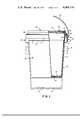
- FIG. 1is a side elevational view of a paint container showing the body and closure assembled and partly in section, and nested in another container shown in phantom lines;
- FIG. 2is a cross-sectional view, on a larger scale than FIG. 1, of portions of the assembled container and closure rim showing the seal and also showing a modification to a bail anchoring means shown in FIG. 1;
- FIG. 3is a side elevational view, on a smaller scale than FIG. 2, of a portion of the container rim showing bail anchoring means.
- a containercomprises a container body generally indicated at 10 in FIG. 1, which is a one-piece moulding in plastics material such as high density polyethylene.
- An annular side wall 11tapers gently at an angle of 2° to the container axis of symmetry from a narrow upper end portion 12 defined by a step 13 to a recessed bottom wall 14 reinforced by an integral radial rib structure shown in part at 15.
- Upper end portion of side wall 11is generally cylindrical and terminates in a lip 16 defining a circular container opening.
- the lip of the containerhas a sealing region comprising a convexly radiused edge 17 at and surrounding the opening and an outer radiused edge 17a.
- the lip 16is thicker than side wall portion 12 immediately below it whereby there is provided a radially outwardly directed shoulder 18 having a lower surface 19 which slopes inwards and downwards to the container side wall at a preferred angle of 38° to the vertical but which may be at any angle between 35° and 45°.
- the skirt 21(FIG. 1) and the upper portion 12 there is integrally formed an intermediate annular rib 22 and a series of equi-angularly disposed radial ribs such as 23.
- the foregoing structureimparts a high degree of rigidity to the upper portion 12 of the container side wall particularly to the portion including rim 16 and resists any tendency for the container body to flex at the lip under the weight of contained paint when a closure has been removed and the lip is held at one position.
- bail anchoring meansTwo diametrically opposed bail anchoring means are integrally formed with the flange 20 and skirt 21.
- One bail anchoring means onlyis shown in FIGS. 2 and 3 at 24.
- the bail anchoring meansmay be adapted to receive a rigid common wire bail 25 as shown in part in FIG. 1 or a more flexible type 26 in preformed plastics materials shown in part in FIG. 2.
- Each bail anchoring means 24comprises a rectangular, open-bottomed, box-like structure. These structures may extend at least to the step 13 in the container side wall or further below as in the embodiment wherein it prevents the jamming together of nested containers.
- Outer walls 27 of the anchoring means 24may be provided with a simple hole 28 (FIG. 1) to receive bent ends of a rigid, common wire bail 25.
- An alternative arrangement in the outer walls 27includes a V-form slot 29 (FIG. 3) leading into an open sided hole 30, the hole being provided with opposing spurs 31. Mushroom-headed pins such as 32 moulded to plastics, strap-type bail 26 (FIG. 2) may be snapped into the holes 30 past the spurs 31.
- Closure 40may be moulded from the same or similar material to the container. It has been found that a high-impact polypropylene closure provides the best combination with a polyethylene container.
- Closure 40comprises a horizontal cover portion 41 which includes a raised annular portion 42 which acts as a spigot with the recessed bottom wall 14 of another container in stacking filled containers one upon the other. From the peripheral edge of horizontal cover 41 there extends upwardly a U-shaped rim 41a defining an inverted annular recess 44.
- a substantially vertical axially inner wall 43 of recess 44is splayed radially outwardly a few degrees and continued some distance below the horizontal cover 41 at 45.
- the inner wall 43is joined to an axially outer wall 48 by a base of the U-shaped rim 41a.
- the basecomprises a wall 46 splayed at an angle of the order of 45° which provides a sealing region of the rim having a seating surface 46a for cooperation with the container lip and forms a junction between inner wall 43 and an upper wall 47 of the base extending outwardly thereof.
- Outer wall 48extends downwardly from the extremity of the upper wall in spaced relationship and substantially parallel to inner wall 43 and is resiliently flexible outwardly from the base.
- annular bead 49having an upper surface 50 which slopes downwardly inwards to the crest of the bead at an angle to the vertical which is slightly greater in the normal unflexed state of the outer wall than the angle of lower surface 19 of the container lip.
- the outer wallalso comprises an annular flared skirt 51 which extends radially outwards from the bead on the other side of the bead from the base at an angle of approximately 40° to the vertical.
- the skirt and a planar annular foot 52 with which it is providedis of a thickness which is substantially no greater than that of the remainder of the outer wall above the bead.
- the above closurelends itself readily to being made by injection moulding techniques with a two part mould in which a male mould part forms the underside surface of the closure and skirt and the upper surface is formed by a female mould part. Removal of the male mould part is effected after removal of the female mould part. Removal of the male mould part is carried out by flexing of the outer wall of the closure thus allowing for the mould part lying within the U-shaped rim to be withdrawn.
- the closureis offered up to the container opening.
- Inner wall extension 45is entered into the opening until a lower surface 53 of the skirt 51 sits on the outer radiused edge 17a of the container lip 16.
- Snap closure by handis effected by commencing pressing the closure down at one spot with the lower palm of one hand which urges the skirt outwards at this point by virtue of its engagement with the edge 17a.
- Local outward flexing of outer wall 48 caused by movement of the skirtquite easily permits the crest of the bead to ride over the lip 16 so that upper surface 50 of the bead 49 now contacts shoulder lower surface 19 of the container lip and splayed surface 46a within the annular recess 44 contacts the inner radiused edge 17 of the container rim.
- the remainder of the operationis merely one of progressive pressure around the edge of the closure with the palms of both hands in opposite directions.
- the pressure required to force the container rim into the closure grooveincreases progressively until at a position opposite the starting point the closure snaps into place.
- flexure of the outer wall of the closurehas increased to a maximum at snap-down point while distortion of the container rim has been minimal.
- peripheral contact between rim radius 17 and splayed seating surface 46ais made in a substantially tangential fashion; substantial portions of shoulder lower surface 19 and bead upper surface 50 are in full contact. No other parts of rim 16 contact any other parts of recess 44.
- outer wall 48 of the closureis in an outwardly resiliently flexed state. Because of its resilient nature, which includes that of the bead and the skirt, a considerable constrictive force is placed upon the shoulder surface 19. Interaction between sloping surfaces 19 and 50 is such as to apply a downward force to the closure thereby seating splayed surface 46a more firmly against the radiused inner edge 17 of the container with a compressive loading. The pressure applied is considerable as it is applied to an annular line of contact between these two surfaces and is sufficient to overcome minute irregularities in their formation and ensure continuous, fluid-tight contact which would not obtain with plane surface-to-surface contact.
- Removal of the closureis quite simple, being merely a matter of applying leverage under the skirt 51 and against the upper surface of flange 20 on the container with a screw driver or like tool. Working progressively around the container will release the closure fully and allow its complete removal with ease.
- skirttends towards an axially straight line relationship with the remainder of wall 48, there is a tendency for the outer wall to flex about a point towards the base thus assisting in removal of the bead from around the shoulder.
- skirtis no thicker than the wall above the bead, there is little or no tendency for the skirt itself to flex relative to the wall above it at least until the bead has been stretched around the shoulder 18.
- the container according to the invention and also according to the embodiment described above,provides an efficient seal for fluid-tightly sealing any liquid and in particular paint within the container while the seal may be made by hand pressure. This is largely because of the single point contact along the line of sealing engagement at edge 17 and surface 46a which provides a continuous unbroken seal.
- the sealis found to be more efficient than in constructions having container bodies and closures engagable over two annular areas of contact, which in practice result in varied pressure being applied first to one and then the other area of contact because of difficulties in manufacture and fitting. In the latter case, leak paths can be caused.
- the sealis also a better seal than one in which there is a large area of contact when surfaces are engaged over a substantial distance in axial cross-section as such surfaces would require to be very carefully prepared to enable them to provide complete sealing contact.
Landscapes
- Engineering & Computer Science (AREA)
- Mechanical Engineering (AREA)
- Closures For Containers (AREA)
Abstract
Description
This invention relates to containers and closures therefor and more particularly to containers manufactured of plastics materials and adapted to hold fluids such as latex-based paints and the like.
Paint, a material which requires a strong light-weight container, traditionally is packaged in cylindrical drum-type cans fabricated from sheet metal - usually tin-plated steel. Due to the nature of paint, it is necessary to have a completely fluid-tight seal between container and lid otherwise drying out of the material would occur thereby rendering it useless. A simple circular lid having a formed peripheral edge such as to provide an interference fit within the mouth of the container provides an adequate seal.
Convenience and cost consideration in the manufacture of containers result in a structure which includes joined seams. These seams are points of weakness where corrosion may begin. With oil based paints, this is not normally a problem but with latex base paints which include a considerable amount of water in their makeup, it can be. To overcome this, the seams must be specially treated to inhibit corrosion thereby adding to the cost of the container.
Metal paint container bodies, again for reasons of ease of production and cost, are usually cylindrical in shape so that when empty they cannot be "nested". Packaging of empty containers, therefore, is bulky and inconvenient from a handling, storing, transportation and expense point of view.
To overcome the disadvantages of metal containers, paint containers made from plastics materials have been made. In these constructions, in order to obtain the fluid-tight seal between the container and closure, an O-ring or other type of resilient seal has had to be used. Plastics containers of known design rely upon such a large constrictive force in the closure to retain them closed that the closures need to be slit to enable them to be removed or their removal is only possible by use of removal tools which render them permanently damaged.
An object of the present invention is to provide a closure of plastics material for a container body which may be removed without damaging the closure thereby enabling it to be re-used.
Another object is to provide a container of plastics material which avoids the need for the use of a seal which is additional to the container body and closure.
According to one aspect of the present invention, there is provided a plastics closure for a container body, the closure having a cover portion surrounded by an annular U-shaped rim, the rim comprising a radially inner axial wall, a spaced radially outer axial wall and a base interconnecting said walls which define between them an axially facing recess for receiving a lip of the body, the outer wall incorporating a radially inwardly projecting bead spaced from the base and a skirt which flares outwardly from the outer wall on the side of the bead remote from the base, and the outer wall being resiliently flexible outwardly to enable snap engagement of the closure with and its release from the container lip.
In the above closure according to the invention, the bead is a relatively stiff portion of the outer wall which applies an annular constricting force to hold the wall in its normal position. The flared skirt acts as a lever which when urged radially outwards and upwards at a specific circumferential point, flexes the outer wall at that point resiliently to stretch the bead to allow it to commence movement around the lip in a closure releasing direction. Outward levering of the skirt circumferentially in a progressive manner from said specific point stretches the bead in corresponding fashion so as completely to unseat it from the lip. The bead serves not only as a constrictive force but because it is a region of relatively greater stiffness than the remainder of the wall, the wall tends to flex at a bend position towards the base upon the application of a radially outwards force upon the skirt so that the bead is pivoted from the bend position.
In addition, the flared skirt tends towards an axially straight line relationship with the remainder of the outer wall whereby when a radially outwards force is applied to the skirt, there is a large component of force also applied radially outwards to the remainder of the wall so as to stretch it. With this construction, the skirt may have a thickness no greater than the remainder of the wall, apart from at the bead, while being sufficiently stiff to cause bead removal without any undue flexing of the skirt itself relative to the wall towards the base. In preferred constructions, the angle of the skirt is between 35° and 45° to the axial direction in its normal and unflexed state with the preferred angle being 40°.
According to another aspect of the present invention, a container comprises a container body and a closure both being of plastics material, the body having an annular wall defining an opening and a lip around the opening, the lip having a sealing region surrounding the opening and a radially outwardly directed shoulder spaced axially along the wall from the sealing region, and the closure having a cover portion surrounded by a U-shaped rim, the rim comprising a radially inner axial wall, a spaced radially outer axial wall and a base interconnecting said walls which define between them an axially facing recess of the rim for insertion of the lip between the walls, the rim also including a sealing region in an area of the inner wall and base, one sealing region being in compressively loaded and tangential engagement with the other region along a single annular line when the lip is received within the rim, and the outer wall incorporating a radially inwardly projecting bead to coact with the shoulder to urge the sealing regions into said engagement, the outer wall being resiliently flexible outwardly for snap engagement around and release from the shoulder.
The container body and closure provide a cheap, easily manufactured, container which, when the two parts are assembled together is fluid tight and the closure will not easily detach itself from the container body under loads applied to it in an accidental manner because of the circumferentially applied constrictive force by the bead. The sealing regions provide an efficient seal as the full compressive loading acting between the sealing regions acts at the single annular line of contact thus creating maximum pressure conditions to make and retain a sealed condition.
The two sealing regions may be surfaces which are of such relative shapes as to provide single annular line of contact when they are engaged. In one preferred arrangement, the rim sealing region is an annular splayed surface extending radially outwards towards the base and the lip sealing region is a convex edge of the lip. Alternatively, however, other shapes may be used to produce a comparable sealing effect. For instance, a convex surface may be provided for the rim sealing region while a chamfered edge of the lip is the lip sealing region; in other constructions both sealing regions may be surface or edge shapes which are convex, or a convex shape may be required to fit into a concave shape of greater radius so that single line contact is achieved. In addition, dependent upon design considerations, the sealing region of the closure may be located at a junction point of the inner wall and base, or upon the inner wall or base. In the latter cases, a step in the wall or base forms a shoulder for engagement by the lip.
An understanding of the invention will be gained from reading the following description taken in conjunction with the accompanying drawings illustrating one embodiment and wherein:
FIG. 1, is a side elevational view of a paint container showing the body and closure assembled and partly in section, and nested in another container shown in phantom lines;
FIG. 2, is a cross-sectional view, on a larger scale than FIG. 1, of portions of the assembled container and closure rim showing the seal and also showing a modification to a bail anchoring means shown in FIG. 1; and
FIG. 3, is a side elevational view, on a smaller scale than FIG. 2, of a portion of the container rim showing bail anchoring means.
A container comprises a container body generally indicated at 10 in FIG. 1, which is a one-piece moulding in plastics material such as high density polyethylene. An annular side wall 11 tapers gently at an angle of 2° to the container axis of symmetry from a narrowupper end portion 12 defined by astep 13 to a recessedbottom wall 14 reinforced by an integral radial rib structure shown in part at 15.
Turning now to FIG. 2. Upper end portion of side wall 11 is generally cylindrical and terminates in alip 16 defining a circular container opening. Generally rectangular in cross-section, the lip of the container has a sealing region comprising a convexly radiused edge 17 at and surrounding the opening and an outerradiused edge 17a. Thelip 16 is thicker thanside wall portion 12 immediately below it whereby there is provided a radially outwardly directedshoulder 18 having alower surface 19 which slopes inwards and downwards to the container side wall at a preferred angle of 38° to the vertical but which may be at any angle between 35° and 45°.
A short distance belowrim 16, there extends aradial flange 20 carrying at its outer peripheral edge adependent skirt 21 generally parallel to and spaced fromupper portion 12. At the upper end of the annular recess formed by theflange 20, the skirt 21 (FIG. 1) and theupper portion 12 there is integrally formed an intermediateannular rib 22 and a series of equi-angularly disposed radial ribs such as 23. The foregoing structure imparts a high degree of rigidity to theupper portion 12 of the container side wall particularly to theportion including rim 16 and resists any tendency for the container body to flex at the lip under the weight of contained paint when a closure has been removed and the lip is held at one position.
Two diametrically opposed bail anchoring means are integrally formed with theflange 20 andskirt 21. One bail anchoring means only is shown in FIGS. 2 and 3 at 24. The bail anchoring means may be adapted to receive a rigidcommon wire bail 25 as shown in part in FIG. 1 or a moreflexible type 26 in preformed plastics materials shown in part in FIG. 2.
Each bail anchoring means 24 comprises a rectangular, open-bottomed, box-like structure. These structures may extend at least to thestep 13 in the container side wall or further below as in the embodiment wherein it prevents the jamming together of nested containers.Outer walls 27 of the anchoring means 24 may be provided with a simple hole 28 (FIG. 1) to receive bent ends of a rigid,common wire bail 25. An alternative arrangement in theouter walls 27 includes a V-form slot 29 (FIG. 3) leading into an opensided hole 30, the hole being provided withopposing spurs 31. Mushroom-headed pins such as 32 moulded to plastics, strap-type bail 26 (FIG. 2) may be snapped into theholes 30 past thespurs 31.
A closure forcontainer body 10 generally indicated at 40 may be moulded from the same or similar material to the container. It has been found that a high-impact polypropylene closure provides the best combination with a polyethylene container. Closure 40 comprises ahorizontal cover portion 41 which includes a raisedannular portion 42 which acts as a spigot with the recessedbottom wall 14 of another container in stacking filled containers one upon the other. From the peripheral edge ofhorizontal cover 41 there extends upwardly aU-shaped rim 41a defining an invertedannular recess 44. A substantially vertical axiallyinner wall 43 ofrecess 44 is splayed radially outwardly a few degrees and continued some distance below thehorizontal cover 41 at 45. Theinner wall 43 is joined to an axiallyouter wall 48 by a base of the U-shapedrim 41a. The base comprises awall 46 splayed at an angle of the order of 45° which provides a sealing region of the rim having a seating surface 46a for cooperation with the container lip and forms a junction betweeninner wall 43 and anupper wall 47 of the base extending outwardly thereof.Outer wall 48 extends downwardly from the extremity of the upper wall in spaced relationship and substantially parallel toinner wall 43 and is resiliently flexible outwardly from the base.
From an inner surface ofouter wall 48, there extends anannular bead 49 having anupper surface 50 which slopes downwardly inwards to the crest of the bead at an angle to the vertical which is slightly greater in the normal unflexed state of the outer wall than the angle oflower surface 19 of the container lip.
The outer wall also comprises an annular flared skirt 51 which extends radially outwards from the bead on the other side of the bead from the base at an angle of approximately 40° to the vertical. The skirt and a planarannular foot 52 with which it is provided is of a thickness which is substantially no greater than that of the remainder of the outer wall above the bead.
As may be seen, the above closure lends itself readily to being made by injection moulding techniques with a two part mould in which a male mould part forms the underside surface of the closure and skirt and the upper surface is formed by a female mould part. Removal of the male mould part is effected after removal of the female mould part. Removal of the male mould part is carried out by flexing of the outer wall of the closure thus allowing for the mould part lying within the U-shaped rim to be withdrawn.
In applying theclosure 40 to thecontainer 10, the closure is offered up to the container opening.Inner wall extension 45 is entered into the opening until alower surface 53 of the skirt 51 sits on the outerradiused edge 17a of thecontainer lip 16. Snap closure by hand is effected by commencing pressing the closure down at one spot with the lower palm of one hand which urges the skirt outwards at this point by virtue of its engagement with theedge 17a. Local outward flexing ofouter wall 48 caused by movement of the skirt quite easily permits the crest of the bead to ride over thelip 16 so thatupper surface 50 of thebead 49 now contacts shoulderlower surface 19 of the container lip and splayed surface 46a within theannular recess 44 contacts the inner radiused edge 17 of the container rim. The remainder of the operation is merely one of progressive pressure around the edge of the closure with the palms of both hands in opposite directions. The pressure required to force the container rim into the closure groove increases progressively until at a position opposite the starting point the closure snaps into place. During this operation, flexure of the outer wall of the closure has increased to a maximum at snap-down point while distortion of the container rim has been minimal.
In the snap-down position, peripheral contact between rim radius 17 and splayed seating surface 46a is made in a substantially tangential fashion; substantial portions of shoulderlower surface 19 and beadupper surface 50 are in full contact. No other parts ofrim 16 contact any other parts ofrecess 44. In its final position,outer wall 48 of the closure is in an outwardly resiliently flexed state. Because of its resilient nature, which includes that of the bead and the skirt, a considerable constrictive force is placed upon theshoulder surface 19. Interaction between slopingsurfaces
Removal of the closure is quite simple, being merely a matter of applying leverage under the skirt 51 and against the upper surface offlange 20 on the container with a screw driver or like tool. Working progressively around the container will release the closure fully and allow its complete removal with ease.
Because the skirt tends towards an axially straight line relationship with the remainder ofwall 48, there is a tendency for the outer wall to flex about a point towards the base thus assisting in removal of the bead from around the shoulder. Although the skirt is no thicker than the wall above the bead, there is little or no tendency for the skirt itself to flex relative to the wall above it at least until the bead has been stretched around theshoulder 18.
The container according to the invention and also according to the embodiment described above, provides an efficient seal for fluid-tightly sealing any liquid and in particular paint within the container while the seal may be made by hand pressure. This is largely because of the single point contact along the line of sealing engagement at edge 17 and surface 46a which provides a continuous unbroken seal. The seal is found to be more efficient than in constructions having container bodies and closures engagable over two annular areas of contact, which in practice result in varied pressure being applied first to one and then the other area of contact because of difficulties in manufacture and fitting. In the latter case, leak paths can be caused. The seal is also a better seal than one in which there is a large area of contact when surfaces are engaged over a substantial distance in axial cross-section as such surfaces would require to be very carefully prepared to enable them to provide complete sealing contact.
Further, because of the flared skirt extending at an angle of 40° to the vertical and there is little or no tendency for it to flex relative to the remainder of the wall above it, there is no reason for the provision of a much thicker section of plastics material for the skirt which could cause shrinkage distortion problems after moulding.
It should be understood that minor changes in configuration and materials may be made without departing from the spirit of the invention and the scope of the appended claims. In particular, the materials mentioned above for the container body and closure may be replaced by other materials which have suitable characteristics for the purpose of the application such as, for example, suitability of modulus of stiffness.
Claims (2)
1. A container comprising a container body and a closure both being of plastics material, the body having an annular wall defining an opening and a lip around the opening, the lip having a sealing region surrounding the opening and a radially outwardly directed shoulder spaced axially along the wall from the sealing region, the shoulder having an abutment surface facing radially outwardly and axially away from the lip, and the closure having a cover portion surrounded by a U-shaped rim, the rim comprising a radially inner axial wall, a spaced radially outer axial wall and a base interconnecting said walls which define between them an axially facing recess of the rim for insertion of the lip between the walls, the rim also including a sealing region at the junction of the inner wall and base, one sealing region being in compressively loaded and tangential engagement with the other region to provide substantially a point contact between the regions in a cross-section along the axis and along a single annular line when the lip is received within the rim, and the outer wall incorporating a radially inwardly projecting bead to coact with the shoulder to urge the lip towards the base of the rim and to urge the sealing regions into said engagement, the outer wall being resiliently flexible outwardly for snap engagement around and release from the shoulder.
2. A container according to claim 1 in which the rim sealing region is an annular splayed surface at the junction of the inner wall and base and the lip sealing region is a convex edge of said lip.
Priority Applications (2)
| Application Number | Priority Date | Filing Date | Title |
|---|---|---|---|
| US05/645,891US4004710A (en) | 1975-12-31 | 1975-12-31 | Container and closure therefor |
| CA266,530ACA1055891A (en) | 1975-12-31 | 1976-11-24 | Container and closure therefor |
Applications Claiming Priority (1)
| Application Number | Priority Date | Filing Date | Title |
|---|---|---|---|
| US05/645,891US4004710A (en) | 1975-12-31 | 1975-12-31 | Container and closure therefor |
Publications (1)
| Publication Number | Publication Date |
|---|---|
| US4004710Atrue US4004710A (en) | 1977-01-25 |
Family
ID=24590884
Family Applications (1)
| Application Number | Title | Priority Date | Filing Date |
|---|---|---|---|
| US05/645,891Expired - LifetimeUS4004710A (en) | 1975-12-31 | 1975-12-31 | Container and closure therefor |
Country Status (2)
| Country | Link |
|---|---|
| US (1) | US4004710A (en) |
| CA (1) | CA1055891A (en) |
Cited By (30)
| Publication number | Priority date | Publication date | Assignee | Title |
|---|---|---|---|---|
| US4090636A (en)* | 1977-08-22 | 1978-05-23 | B.W. Norton Manufacturing Co. Inc. | Metal paint pail cover |
| US4209107A (en)* | 1978-11-15 | 1980-06-24 | Crisci Victor E | Container with vapor lock closure |
| US4228916A (en)* | 1978-07-20 | 1980-10-21 | Standard Container Company | Plastic paint bucket with metal sealing ring |
| US4280635A (en)* | 1978-07-27 | 1981-07-28 | Murphy Richard W | Vase cover |
| US4357042A (en)* | 1980-09-19 | 1982-11-02 | Sears, Roebuck And Co. | Bail |
| US4387828A (en)* | 1980-02-11 | 1983-06-14 | Yates Jr George | Plastic container and lid |
| FR2521530A1 (en)* | 1982-02-16 | 1983-08-19 | Peintures Ind Ass | Device for container closing and handling - has lid held in by friction and handle held by plastics ring |
| US4483455A (en)* | 1982-08-20 | 1984-11-20 | The Carousel Group, Inc. | Food storage container system |
| US4496070A (en)* | 1982-09-29 | 1985-01-29 | Lane Jr Samuel H | Container and lid forming a disposable mold |
| US4881658A (en)* | 1988-08-17 | 1989-11-21 | Cleveland Container Corporation | Sealed container |
| USD308942S (en) | 1987-12-23 | 1990-07-03 | Sweetheart International Limited | Container |
| US4940158A (en)* | 1987-09-22 | 1990-07-10 | American National Can Company | Container and seam ring for container |
| US4974742A (en)* | 1990-01-09 | 1990-12-04 | American National Can Company | Container with foldable handles |
| US5231376A (en)* | 1992-03-05 | 1993-07-27 | Arcarese Frank V | Tool transport container apparatus |
| US5244113A (en)* | 1992-08-24 | 1993-09-14 | Northwestern Bottle Company | Container lid assembly |
| USD348176S (en) | 1992-08-05 | 1994-06-28 | Whirley Industries, Inc. | Beverage container |
| US5573118A (en)* | 1996-03-05 | 1996-11-12 | Walbro Corporation | Nestable open head drum |
| US5577632A (en)* | 1994-01-27 | 1996-11-26 | Plastican, Inc. | Pail safety ring |
| USD395118S (en) | 1996-03-05 | 1998-06-09 | Walbro Corporation | Drum combined with a cover |
| US6021917A (en)* | 1996-03-07 | 2000-02-08 | Industrial Containers Ltd. | Pail and plastic lid comprising non-linear, flexible ribs |
| US6360886B1 (en) | 2000-03-13 | 2002-03-26 | Kerr Corporation | Capsule for use in preparing a dental amalgam |
| US6491185B1 (en)* | 1999-11-15 | 2002-12-10 | United States Can Company | Molded container including plug with multiple locking arms |
| US6783021B2 (en)* | 2002-02-01 | 2004-08-31 | Kamaljit S. Kaura | Canister with air-tight lid and spring camping handle |
| USD545622S1 (en)* | 2005-12-29 | 2007-07-03 | Gomez Elias G | Combined pill crusher and drinking tumbler |
| GB2444038A (en)* | 2006-11-22 | 2008-05-28 | Plastic Can Company Ltd | Method and apparatus for moulding a container with a handle |
| US20110308471A1 (en)* | 2006-08-15 | 2011-12-22 | Droll Yankees, Inc. | Bird feeder |
| USD678650S1 (en)* | 2012-03-20 | 2013-03-19 | Jordan Kimball Giles | Drum |
| US8757453B1 (en)* | 2007-01-10 | 2014-06-24 | Sven O. Olsson | Pouring spout |
| CN105173336A (en)* | 2015-10-23 | 2015-12-23 | 珠海格力电器股份有限公司 | Pail assembly |
| EP2966000B1 (en) | 2014-07-08 | 2016-09-07 | Clariant Production (France) S.A.S. | Container |
Citations (6)
| Publication number | Priority date | Publication date | Assignee | Title |
|---|---|---|---|---|
| US3137409A (en)* | 1963-01-23 | 1964-06-16 | Sweetheart Plastics | Container cover |
| US3339792A (en)* | 1965-06-23 | 1967-09-05 | Owens Illinois Inc | Container and closure cap for same |
| US3372834A (en)* | 1966-01-24 | 1968-03-12 | Robert A. Ayotte | Container and closure assembly |
| US3474928A (en)* | 1968-03-28 | 1969-10-28 | Robert S Hurtt | Container having snap fastening means |
| US3804289A (en)* | 1972-03-17 | 1974-04-16 | Vulcan Plastics Inc | Container and closure |
| US3811597A (en)* | 1972-04-17 | 1974-05-21 | Continental Can Co | Plastic container |
- 1975
- 1975-12-31USUS05/645,891patent/US4004710A/ennot_activeExpired - Lifetime
- 1976
- 1976-11-24CACA266,530Apatent/CA1055891A/ennot_activeExpired
Patent Citations (6)
| Publication number | Priority date | Publication date | Assignee | Title |
|---|---|---|---|---|
| US3137409A (en)* | 1963-01-23 | 1964-06-16 | Sweetheart Plastics | Container cover |
| US3339792A (en)* | 1965-06-23 | 1967-09-05 | Owens Illinois Inc | Container and closure cap for same |
| US3372834A (en)* | 1966-01-24 | 1968-03-12 | Robert A. Ayotte | Container and closure assembly |
| US3474928A (en)* | 1968-03-28 | 1969-10-28 | Robert S Hurtt | Container having snap fastening means |
| US3804289A (en)* | 1972-03-17 | 1974-04-16 | Vulcan Plastics Inc | Container and closure |
| US3811597A (en)* | 1972-04-17 | 1974-05-21 | Continental Can Co | Plastic container |
Cited By (34)
| Publication number | Priority date | Publication date | Assignee | Title |
|---|---|---|---|---|
| US4090636A (en)* | 1977-08-22 | 1978-05-23 | B.W. Norton Manufacturing Co. Inc. | Metal paint pail cover |
| US4228916A (en)* | 1978-07-20 | 1980-10-21 | Standard Container Company | Plastic paint bucket with metal sealing ring |
| US4280635A (en)* | 1978-07-27 | 1981-07-28 | Murphy Richard W | Vase cover |
| US4209107A (en)* | 1978-11-15 | 1980-06-24 | Crisci Victor E | Container with vapor lock closure |
| US4387828A (en)* | 1980-02-11 | 1983-06-14 | Yates Jr George | Plastic container and lid |
| US4357042A (en)* | 1980-09-19 | 1982-11-02 | Sears, Roebuck And Co. | Bail |
| FR2521530A1 (en)* | 1982-02-16 | 1983-08-19 | Peintures Ind Ass | Device for container closing and handling - has lid held in by friction and handle held by plastics ring |
| US4483455A (en)* | 1982-08-20 | 1984-11-20 | The Carousel Group, Inc. | Food storage container system |
| US4496070A (en)* | 1982-09-29 | 1985-01-29 | Lane Jr Samuel H | Container and lid forming a disposable mold |
| US4940158A (en)* | 1987-09-22 | 1990-07-10 | American National Can Company | Container and seam ring for container |
| USD308942S (en) | 1987-12-23 | 1990-07-03 | Sweetheart International Limited | Container |
| US4881658A (en)* | 1988-08-17 | 1989-11-21 | Cleveland Container Corporation | Sealed container |
| US4974742A (en)* | 1990-01-09 | 1990-12-04 | American National Can Company | Container with foldable handles |
| US5231376A (en)* | 1992-03-05 | 1993-07-27 | Arcarese Frank V | Tool transport container apparatus |
| USD348176S (en) | 1992-08-05 | 1994-06-28 | Whirley Industries, Inc. | Beverage container |
| US5244113A (en)* | 1992-08-24 | 1993-09-14 | Northwestern Bottle Company | Container lid assembly |
| US5577632A (en)* | 1994-01-27 | 1996-11-26 | Plastican, Inc. | Pail safety ring |
| US5573118A (en)* | 1996-03-05 | 1996-11-12 | Walbro Corporation | Nestable open head drum |
| USD395118S (en) | 1996-03-05 | 1998-06-09 | Walbro Corporation | Drum combined with a cover |
| US6021917A (en)* | 1996-03-07 | 2000-02-08 | Industrial Containers Ltd. | Pail and plastic lid comprising non-linear, flexible ribs |
| US6491185B1 (en)* | 1999-11-15 | 2002-12-10 | United States Can Company | Molded container including plug with multiple locking arms |
| US6360886B1 (en) | 2000-03-13 | 2002-03-26 | Kerr Corporation | Capsule for use in preparing a dental amalgam |
| US6439380B1 (en) | 2000-03-13 | 2002-08-27 | Kerr Corporation | Capsule for use in preparing a dental amalgam |
| US6783021B2 (en)* | 2002-02-01 | 2004-08-31 | Kamaljit S. Kaura | Canister with air-tight lid and spring camping handle |
| USD545622S1 (en)* | 2005-12-29 | 2007-07-03 | Gomez Elias G | Combined pill crusher and drinking tumbler |
| US20110308471A1 (en)* | 2006-08-15 | 2011-12-22 | Droll Yankees, Inc. | Bird feeder |
| US8662015B2 (en)* | 2006-08-15 | 2014-03-04 | Droll Yankees, Inc. | Bird feeder |
| US20100104885A1 (en)* | 2006-11-22 | 2010-04-29 | The Plastic Can Company Limited | Injection-moulded preform for use in making a container, and a method and apparatus for making a container with a handle |
| GB2444038A (en)* | 2006-11-22 | 2008-05-28 | Plastic Can Company Ltd | Method and apparatus for moulding a container with a handle |
| US8757453B1 (en)* | 2007-01-10 | 2014-06-24 | Sven O. Olsson | Pouring spout |
| USD678650S1 (en)* | 2012-03-20 | 2013-03-19 | Jordan Kimball Giles | Drum |
| EP2966000B1 (en) | 2014-07-08 | 2016-09-07 | Clariant Production (France) S.A.S. | Container |
| US10807773B2 (en) | 2014-07-08 | 2020-10-20 | Clariant Healthcare Packaging (France) S.A.S. | Container |
| CN105173336A (en)* | 2015-10-23 | 2015-12-23 | 珠海格力电器股份有限公司 | Pail assembly |
Also Published As
| Publication number | Publication date |
|---|---|
| CA1055891A (en) | 1979-06-05 |
Similar Documents
| Publication | Publication Date | Title |
|---|---|---|
| US4004710A (en) | Container and closure therefor | |
| US4079857A (en) | Containers and closures | |
| US6880716B2 (en) | Plastic lid construction | |
| US4293080A (en) | Container construction | |
| US4458825A (en) | Plastic container and closure assembly | |
| US4452382A (en) | Container closure | |
| US4887735A (en) | Container | |
| US6250494B1 (en) | Plastic containers with interlocking lids | |
| US4512493A (en) | Molded bucket and lid having high stack strength | |
| US4279358A (en) | Container lid | |
| US20090026203A1 (en) | Plastic container with double lock lid and tear band | |
| CA2066775A1 (en) | Pressure lid can | |
| WO2003026979A3 (en) | Closure system | |
| EP1345815B1 (en) | Closure assembly and method | |
| US3840144A (en) | Plastic cover for cylindrical containers of large capacity | |
| JPH0848357A (en) | Screw cap with welded ring | |
| IE48381B1 (en) | Frangible closure for containers | |
| US4090636A (en) | Metal paint pail cover | |
| AU2007312886A1 (en) | Can closure arrangement | |
| US4572399A (en) | Plastic container having inwardly formed flange | |
| US3469748A (en) | Closure seal and cap | |
| US5839604A (en) | Lid having flexibly hinged wall portions and container therefor | |
| CA2352489C (en) | Pail and lid assembly | |
| GB2251431A (en) | Closures for containers | |
| EP4520679A2 (en) | Improved three-piece container assembly |
Legal Events
| Date | Code | Title | Description |
|---|---|---|---|
| AS | Assignment | Owner name:POLYSAR PLASTICS, INC. Free format text:ASSIGNMENT OF ASSIGNORS INTEREST.;ASSIGNORS:POLYSAR LIMITED;POLYSAR INCORPORTED;REEL/FRAME:005971/0001 Effective date:19790410 Owner name:POLYSAR PLASTICS, INC. Free format text:ASSIGNMENT OF ASSIGNORS INTEREST;ASSIGNORS:POLYSAR LIMITED;POLYSAR INCORPORTED;REEL/FRAME:005971/0001 Effective date:19790410 | |
| AS | Assignment | Owner name:WHIRLPOOL FINANCIAL CORPORATION A CORP. OF DELAWA Free format text:SECURITY INTEREST;ASSIGNOR:BERRY PLASTICS CORPORATION A CORP. OF DELAWARE;REEL/FRAME:006041/0583 Effective date:19920212 | |
| AS | Assignment | Owner name:BERRY PLASTICS CORPORATION, INDIANA Free format text:RELEASE BY SECURED PARTY;ASSIGNOR:WHIRLPOOL FINANCIAL CORPORATION;REEL/FRAME:006952/0950 Effective date:19940421 |