US4003376A - Apparatus for straightening the spinal column - Google Patents
Apparatus for straightening the spinal columnDownload PDFInfo
- Publication number
- US4003376A US4003376AUS05/607,108US60710875AUS4003376AUS 4003376 AUS4003376 AUS 4003376AUS 60710875 AUS60710875 AUS 60710875AUS 4003376 AUS4003376 AUS 4003376A
- Authority
- US
- United States
- Prior art keywords
- spinal column
- support
- adjacent
- elongated member
- elongated
- Prior art date
- Legal status (The legal status is an assumption and is not a legal conclusion. Google has not performed a legal analysis and makes no representation as to the accuracy of the status listed.)
- Expired - Lifetime
Links
- 206010023509KyphosisDiseases0.000description11
- 238000000034methodMethods0.000description8
- 208000007623LordosisDiseases0.000description6
- 210000000988bone and boneAnatomy0.000description5
- 230000004927fusionEffects0.000description4
- 208000032170Congenital AbnormalitiesDiseases0.000description3
- 210000003815abdominal wallAnatomy0.000description3
- 238000013459approachMethods0.000description3
- 238000012937correctionMethods0.000description3
- 208000005377MeningomyeloceleDiseases0.000description2
- 208000004210Pressure UlcerDiseases0.000description2
- 230000007812deficiencyEffects0.000description2
- 238000012986modificationMethods0.000description2
- 230000004048modificationEffects0.000description2
- 230000001769paralizing effectEffects0.000description2
- 238000004904shorteningMethods0.000description2
- 208000001916spina bifida cysticaDiseases0.000description2
- 206010011985Decubitus ulcerDiseases0.000description1
- 210000003489abdominal muscleAnatomy0.000description1
- 230000004075alterationEffects0.000description1
- 210000001367arteryAnatomy0.000description1
- 230000007547defectEffects0.000description1
- 230000006870functionEffects0.000description1
- 239000007943implantSubstances0.000description1
- 238000003780insertionMethods0.000description1
- 230000037431insertionEffects0.000description1
- 210000004446longitudinal ligamentAnatomy0.000description1
- 230000001045lordotic effectEffects0.000description1
- 210000003205muscleAnatomy0.000description1
- 230000000399orthopedic effectEffects0.000description1
- 210000003049pelvic boneAnatomy0.000description1
- 230000008569processEffects0.000description1
- 230000001737promoting effectEffects0.000description1
- 210000004872soft tissueAnatomy0.000description1
- 210000003462veinAnatomy0.000description1
- 210000002517zygapophyseal jointAnatomy0.000description1
Images


Classifications
- A—HUMAN NECESSITIES
- A61—MEDICAL OR VETERINARY SCIENCE; HYGIENE
- A61B—DIAGNOSIS; SURGERY; IDENTIFICATION
- A61B17/00—Surgical instruments, devices or methods
- A61B17/56—Surgical instruments or methods for treatment of bones or joints; Devices specially adapted therefor
- A61B17/58—Surgical instruments or methods for treatment of bones or joints; Devices specially adapted therefor for osteosynthesis, e.g. bone plates, screws or setting implements
- A61B17/68—Internal fixation devices, including fasteners and spinal fixators, even if a part thereof projects from the skin
- A61B17/70—Spinal positioners or stabilisers, e.g. stabilisers comprising fluid filler in an implant
- A—HUMAN NECESSITIES
- A61—MEDICAL OR VETERINARY SCIENCE; HYGIENE
- A61B—DIAGNOSIS; SURGERY; IDENTIFICATION
- A61B17/00—Surgical instruments, devices or methods
- A61B17/56—Surgical instruments or methods for treatment of bones or joints; Devices specially adapted therefor
- A61B17/58—Surgical instruments or methods for treatment of bones or joints; Devices specially adapted therefor for osteosynthesis, e.g. bone plates, screws or setting implements
- A61B17/68—Internal fixation devices, including fasteners and spinal fixators, even if a part thereof projects from the skin
- A61B17/80—Cortical plates, i.e. bone plates; Instruments for holding or positioning cortical plates, or for compressing bones attached to cortical plates
- A61B17/8061—Cortical plates, i.e. bone plates; Instruments for holding or positioning cortical plates, or for compressing bones attached to cortical plates specially adapted for particular bones
- A—HUMAN NECESSITIES
- A61—MEDICAL OR VETERINARY SCIENCE; HYGIENE
- A61B—DIAGNOSIS; SURGERY; IDENTIFICATION
- A61B17/00—Surgical instruments, devices or methods
- A61B17/56—Surgical instruments or methods for treatment of bones or joints; Devices specially adapted therefor
- A61B17/58—Surgical instruments or methods for treatment of bones or joints; Devices specially adapted therefor for osteosynthesis, e.g. bone plates, screws or setting implements
- A61B17/68—Internal fixation devices, including fasteners and spinal fixators, even if a part thereof projects from the skin
- A61B17/82—Internal fixation devices, including fasteners and spinal fixators, even if a part thereof projects from the skin for bone cerclage
Definitions
- This inventionis in the field of medical devices and methods for correcting spinal column deficiencies.
- a devicewas designed to satisfy the following criteria: (1) Correct the deformity without shortening of the spine but depend on the ligamentus structures for support; (2) Maintain the correction until spinal fusion has occurred from the apex of the upper lordosis to the apex of the lower lordosis across the kyphosis; (3) If the soft tissue (arteries, veins or abdominal wall) will not allow immediate correction, a simple staged procedure can be used to gradually correct the kyphosis.
- One embodiment of the present inventionis a spinal column straightener including a rigid support insertable adjacent the spinal column so as to extend lengthwise along the spinal column, the support having first and second opposite longitudinally extending edge portions and further including means extendable around the spinal column from the first to the second edge portions with the means being operable to force the support against the spinal column along the entire length of the support.
- Another embodiment of the present inventionis a method of straightening the spinal column including the steps of positioning a rigid elongated member adjacent the forward side of the spinal column, positioning the member to extend lengthwise along the spinal column, and forcing the spinal column against the elongated member along the entire length of the member straightening the spinal column.
- a further object of the present inventionis to provide a new and improved method for straightening the spinal column.
- FIG. 1is a schematic side view of a spinal column with the plate assembly incorporating the present invention attached thereto.
- FIG. 2is an enlarged perspective view of the plate assembly.
- FIG. 3is an enlarged fragmentary view looking in the direction of arrows 3--3 of FIG. 1 of the preferred embodiment of the present invention.
- FIG. 4is the same view as FIG. 3 only showing an alternative embodiment of the plate assembly.
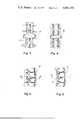
- FIG. 5is an enlarged fragmentary side view of a portion of the plate assembly mounted to the spinal column in FIG. 1.
- FIG. 6is the same view as FIG. 5 only showing the band of the plate assembly located inwardly as compared to the band positioning in FIG. 5.
- FIG. 7is an enlarged cross-sectional view taken along the line 7--7 of FIG. 6, viewed in the direction of the arrows and rotated clockwise 90°.
- FIG. 8is an enlarged cross-sectional view taken along the line 8--8 of FIG. 5, viewed in the direction of the arrows and rotated clockwise 90°.
- FIG. 9is a perspective view of another embodiment of the plate assembly incorporating the present invention.
- Apparatus 12includes an elongated member 13 (FIG. 2) forced against the spinal column by a pair of U-shaped bolts 14 and 15, respectively, secured to bands 16 and 17 by internally threaded nuts 18, 19, and 20, 21.
- the method of straightening a spinal columnincludes the step of positioning member 13 adjacent the forward side 22 (FIG. 1) of spinal column 11 with member 13 extending lengthwise along the spinal column.
- Member 13is essentially a straight or slightly lordotic 10 degree to 15 degree plate that attaches to the vertebral bodies anteriorly with cancellous screws to keep the plate from migrating or slipping off the vertebral bodies.
- a pair of slots 23 and 24are provided respectively in the top end 25 and bottom end 26 of member 13. Bone screws 27 and 28 respectively extend through slots 23 and 24 and are threaded into the vertebral bodies.
- member 13is fastened directly to the spinal column.
- Member 13is rigid and has a concave configuration 29 facing the spinal column.
- top end 25 and bottom end 26flare outwardly of concave configuration 29 to insure that the ends of the member do not dig into the spinal column as the nuts 18 through 21 are tightened.
- the opposite surface 30 of member 13 facing away from the spinal column and forwardly of the spinal columnis in contact with bolts 14 and 15.
- Surface 30includes a plurality of grooves 31 and ridges 32 with each ridge having a height of approximately 1 to 11/4 centimeters. Each U-shaped bolt fits within a groove 31 thereby limiting relative motion between bolts 14 and 15 and member 13.
- Bolt 14will now be described it being understood that a similar description applies to bolt 15.
- Bolt 14includes a pair of parallel rods 33 and 34 which are externally threaded so as to receive nuts 18 and 19. Rods 33 and 34 are integrally joined together perpendicularly to rod 35 which extends through one of the grooves 31.
- Bolts 14 and 15 in conjunction with bands 16 and 17extend from member 13 around the spinal column and back to member 13 being operable to force the spinal column to contact member 13 along the entire length of member 13 thereby straightening the spinal column.
- the spinal columnis forced against member 13 so as to assume the concave configuration 29 as well as to contact the flared ends 25 and 26 of member 13.
- Band 17will now be described it being understood that a similar description applies to band 16.
- Band 17has a pair of opposite ends 36 and 37 with the band being of constant thickness except at groove 38 where the band is considerably weakened.
- a pair of holes 39 and 40are positioned between end 36 and groove 38 to receive the opposite ends of bolt 15.
- the height of band 17is likewise constant except between holes 39 and 40 where the height increases.
- Groove 38is provided so as to allow for the braking off of the portion of the band extending between groove 38 and end 37.
- Portion 41 of band 17is therefore used as a handle to help the surgeon guide portion 42 of the band into the correct location behind the spinal column.
- Portion 41may then be bent along groove 38 so as to break from portion 42 which remains adjacent the spinal column.
- band Member 13extends lengthwise along the spinal column whereas bands 16 and 17 have lengths which extend across the spinal column.
- Bolts 14 and 15 and nuts 18 through 21limit movement of bands 16 and 17 relative to the U-shaped bolts.
- Nuts 18 through 21may be adjusted through two small posterior incisions.
- the bandis inserted between the intravertebral foraman posterior to the posterior longitudinal ligament and anterior to the cord if the child has function in the cord at that level or there are no posterior elements. With posterior elements, the band runs over the facet joints, the lamina, and part of the spinous process such as shown in FIG. 5.
- the kyphosisis pulled to the plate and the lordosis is corrected by posterior thrust of the surface of the plate.
- the intravertebral discsare removed and the defect is grafted with cancellous bone. If the kyphosis is severe and the abdominal wall is too taunt, the patient can be closed and two or three weeks later through a small posterior incision, the nuts may be tightened slowly stretching out the abdominal wall. It is believed advisable to accomplish the above procedure when the patient is around four to six years of age. Likewise, it is advisable to put the patient in an external support until fusion has occurred.
- FIGS. 7 and 8are respectively cross-sectional views of the plate assembly shown in FIGS. 6 and 5.
- Member 13in addition to having a concave configuration 29 (FIG. 2) which extends from the top flared out end 25 to the bottom flared out end 26, has a second concave configuration 43 (FIGS. 7 and 8) to complementarily receive the rounded configuration of the spinal column.
- Concave configuration 43extends across the spinal column as compared to the concave configuration 29 which extends the length of the column.
- Concave configuration 43is constant from the top end 25 to the bottom end 26 of member 13.
- bands 16 and 17are caused to move toward member 13.
- Bolts 14 and 15extend not only across surface 30 of member 13 but likewise extend from the longitudinally extending edge portions of member 13 and outwardly of the spinal column to bands 16 and 17.
- band 50is identical to bands 16 and 17 with the exception that band 50 has a uniform height from one end of the band to the opposite end of the band. Likewise, band 50 is provided with a groove enabling the handle portion to be broken off of the band after the band is inserted behind the spinal column. Band 50 is shown in FIG. 4 with the handle portion removed therefrom.
- member 13was not provided with a concave configuration 29 but instead was flat.
- Another variation contemplated and included hereinis the addition of clamps mounted to surface 30 of member 13 with surface 30 being smooth. Bolts 14 and 15 are then attached to member 13 by the clamps mounted thereon preventing relative motion between member 13 and bolts 14 and 15.
- FIG. 9Another embodiment of the apparatus for straightening the spinal column is shown in FIG. 9.
- Apparatus 50is identical with apparatus 12 previously described except that the elongated member 51 is flat and does not include the concave configuration 29 of apparatus 12.
- the pair of U-shaped bolts 52 and 53are secured to the elongated member 51 by a pair of clamps 54 and 55.
- top end 56 and bottom end 57 of elongated member 51do not flare outwardly as described for apparatus 12.
- Surface 58 of elongated member 51is provided with a concave configuration 59 similar to concave configuration 43 of apparatus 12 (FIG. 7).
- Elongated member 51is attached to the spine with bone screws 60 and 61 in the manner identical to apparatus 12.
- bands 62 and 63are positioned on rods 52 and 53 and secured thereby by conventional hexagonally shaped nuts 64 in a manner identical to that described for apparatus 12.
- Clamps 54 and 55are secured to the elongated member 51 by screws 65 and are held in grooves 66 by the clamps.
- Additional holes 67are provided in the elongated member for receiving screws 65 in the event that the clamps are to be moved to adjacent grooves 66.
- Clamp 55prevents the slippage of the U-shaped bolts before and after insertion.
- Clamps 54 and 55may also be mounted to member 13 for holding bolts 14 and 15.
Landscapes
- Health & Medical Sciences (AREA)
- Orthopedic Medicine & Surgery (AREA)
- Life Sciences & Earth Sciences (AREA)
- Surgery (AREA)
- Neurology (AREA)
- Heart & Thoracic Surgery (AREA)
- Engineering & Computer Science (AREA)
- Biomedical Technology (AREA)
- Nuclear Medicine, Radiotherapy & Molecular Imaging (AREA)
- Medical Informatics (AREA)
- Molecular Biology (AREA)
- Animal Behavior & Ethology (AREA)
- General Health & Medical Sciences (AREA)
- Public Health (AREA)
- Veterinary Medicine (AREA)
- Prostheses (AREA)
- Surgical Instruments (AREA)
Abstract
Description
1. Field of the Invention
This invention is in the field of medical devices and methods for correcting spinal column deficiencies.
2. Description of the Prior Art
One of the most perplexing problems to the pediatric orthopedic surgeon or spine surgeon has been paralytic kyphosis of the spine, particularly the meningomyelocele. The reason for the severe problems is the early age of onset, decubitus ulcers, inability to brace, difficulty in surgically correcting the kyphosis without substantially shortening the trunk and difficulty maintaining the correction. Kyphosis of the spine is a selfperpetuating problem. In the meningomyelocele or paralytic kyphosis the individual's paravertebral muscles are ineffectual and the abdominal muscles increase or perpetuate the kyphosis. Due to the early onset and the early fixation of the spine and perpetual pressure sores, surgeons have attempted to correct this problem early. Some have advocated removal of the apical vertebral body of the kyphosis and fusion which shortens the spine. The deformity recurs rapidly because the fusion is not long enough and does not correct the lordosis that occurs above and below the kyphosis. Thus, the spine has to be straightened from the apex of the upper lordosis to the apex of the lordosis below the kyphotic area. Due to the fact that this deformity occurs so early in life it necessitates that something be done early and the attack has to be anteriorly. The absence of posterior elements of the spine and the cancellous bone of the vertebral body makes the conventional internal fixation devices useless. Therefore, a device was designed to satisfy the following criteria: (1) Correct the deformity without shortening of the spine but depend on the ligamentus structures for support; (2) Maintain the correction until spinal fusion has occurred from the apex of the upper lordosis to the apex of the lower lordosis across the kyphosis; (3) If the soft tissue (arteries, veins or abdominal wall) will not allow immediate correction, a simple staged procedure can be used to gradually correct the kyphosis.
Some devices have been provided for straightening or supporting the spine. For example, U.S. Pat. Nos. 2,702,031 issued to H. L. Wenger and 3,242,922 issued to C. B. Thomas disclose supporting devices mountable to the pelvic bone extending upwardly to support the spinal column. Another approach has been to replace one or more natural vertebrae with an artificial device such as disclosed in U.S. Pat. No. 3,426,364 issued to W. V. Lumb. Another approach disclosed in U.S. Pat. No. 2,774,350 issued to C. S. Cleveland, Jr. provides tension to a vertebrae in order to correct the deficiency. Other devices such as disclosed in U.S. Pat. Nos. 1,950,799 issued to C. P. Jones and 3,693,616 issued to Roaf et al disclose devices for securing bones together. Another device disclosed in U.S. Pat. No. 3,565,066 issued to Robert Roaf discloses an implant for causing the displaced vertebrae to be drawn toward a rigid member. The method disclosed in U.S. Pat. No. 3,648,691 issued to William Lumb provides an appliance for use in bridging one or more diseased or damaged vertebrae.
One embodiment of the present invention is a spinal column straightener including a rigid support insertable adjacent the spinal column so as to extend lengthwise along the spinal column, the support having first and second opposite longitudinally extending edge portions and further including means extendable around the spinal column from the first to the second edge portions with the means being operable to force the support against the spinal column along the entire length of the support.
Another embodiment of the present invention is a method of straightening the spinal column including the steps of positioning a rigid elongated member adjacent the forward side of the spinal column, positioning the member to extend lengthwise along the spinal column, and forcing the spinal column against the elongated member along the entire length of the member straightening the spinal column.
It is an object of the present invention to provide a new and improved apparatus for straightening a spinal column.
A further object of the present invention is to provide a new and improved method for straightening the spinal column.
Related objects and advantages of the present invention will be apparent from the following description.
FIG. 1 is a schematic side view of a spinal column with the plate assembly incorporating the present invention attached thereto.
FIG. 2 is an enlarged perspective view of the plate assembly.
FIG. 3 is an enlarged fragmentary view looking in the direction ofarrows 3--3 of FIG. 1 of the preferred embodiment of the present invention.
FIG. 4 is the same view as FIG. 3 only showing an alternative embodiment of the plate assembly.
FIG. 5 is an enlarged fragmentary side view of a portion of the plate assembly mounted to the spinal column in FIG. 1.
FIG. 6 is the same view as FIG. 5 only showing the band of the plate assembly located inwardly as compared to the band positioning in FIG. 5.
FIG. 7 is an enlarged cross-sectional view taken along theline 7--7 of FIG. 6, viewed in the direction of the arrows and rotated clockwise 90°.
FIG. 8 is an enlarged cross-sectional view taken along the line 8--8 of FIG. 5, viewed in the direction of the arrows and rotated clockwise 90°.
FIG. 9 is a perspective view of another embodiment of the plate assembly incorporating the present invention.
For the purposes of promoting an understanding of the principles of the invention, reference will now be made to the embodiments illustrated in the drawings and specific language will be used to describe the same. It will nevertheless be understood that no limitation of the scope of the invention is thereby intended, such alterations and further modifications in the illustrated device, and such further applications of the principles of the invention as illustrated therein being contemplated as would normally occur to one skilled in the art to which the invention relates.
Referring now more particularly to FIG. 1, there is shown ahuman subject 10 with a spinal column 11 straightened by theapparatus 12 incorporating the present invention.Apparatus 12 includes an elongated member 13 (FIG. 2) forced against the spinal column by a pair of U-shapedbolts bands nuts
The method of straightening a spinal column includes the step of positioningmember 13 adjacent the forward side 22 (FIG. 1) of spinal column 11 withmember 13 extending lengthwise along the spinal column.Member 13 is essentially a straight or slightly lordotic 10 degree to 15 degree plate that attaches to the vertebral bodies anteriorly with cancellous screws to keep the plate from migrating or slipping off the vertebral bodies. A pair ofslots top end 25 andbottom end 26 ofmember 13.Bone screws slots member 13 is fastened directly to the spinal column.Member 13 is rigid and has aconcave configuration 29 facing the spinal column. Thetop end 25 andbottom end 26 flare outwardly ofconcave configuration 29 to insure that the ends of the member do not dig into the spinal column as thenuts 18 through 21 are tightened. Theopposite surface 30 ofmember 13 facing away from the spinal column and forwardly of the spinal column is in contact withbolts Surface 30 includes a plurality ofgrooves 31 andridges 32 with each ridge having a height of approximately 1 to 11/4 centimeters. Each U-shaped bolt fits within agroove 31 thereby limiting relative motion betweenbolts member 13.
FIGS. 7 and 8 are respectively cross-sectional views of the plate assembly shown in FIGS. 6 and 5.Member 13, in addition to having a concave configuration 29 (FIG. 2) which extends from the top flared outend 25 to the bottom flared outend 26, has a second concave configuration 43 (FIGS. 7 and 8) to complementarily receive the rounded configuration of the spinal column.Concave configuration 43 extends across the spinal column as compared to theconcave configuration 29 which extends the length of the column.Concave configuration 43 is constant from thetop end 25 to thebottom end 26 ofmember 13.
By tighteningnuts 18 through 21,bands member 13.Bolts surface 30 ofmember 13 but likewise extend from the longitudinally extending edge portions ofmember 13 and outwardly of the spinal column tobands
In the alternate embodiment of the band shown in FIG. 4,band 50 is identical tobands band 50 is provided with a groove enabling the handle portion to be broken off of the band after the band is inserted behind the spinal column.Band 50 is shown in FIG. 4 with the handle portion removed therefrom. Many other variations are contemplated and included in the present invention. For example, in one embodiment,member 13 was not provided with aconcave configuration 29 but instead was flat. Another variation contemplated and included herein is the addition of clamps mounted to surface 30 ofmember 13 withsurface 30 being smooth.Bolts member 13 by the clamps mounted thereon preventing relative motion betweenmember 13 andbolts
Another embodiment of the apparatus for straightening the spinal column is shown in FIG. 9.Apparatus 50 is identical withapparatus 12 previously described except that theelongated member 51 is flat and does not include theconcave configuration 29 ofapparatus 12. In addition, the pair ofU-shaped bolts elongated member 51 by a pair ofclamps
Thetop end 56 andbottom end 57 ofelongated member 51 do not flare outwardly as described forapparatus 12.Surface 58 ofelongated member 51 is provided with aconcave configuration 59 similar toconcave configuration 43 of apparatus 12 (FIG. 7).Elongated member 51 is attached to the spine withbone screws apparatus 12. Likewise,bands rods apparatus 12.Clamps elongated member 51 byscrews 65 and are held ingrooves 66 by the clamps.Additional holes 67 are provided in the elongated member for receivingscrews 65 in the event that the clamps are to be moved toadjacent grooves 66.Clamp 55 prevents the slippage of the U-shaped bolts before and after insertion.Clamps member 13 for holdingbolts
While the invention has been illustrated and described in detail in the drawings and foregoing description, the same is to be considered as illustrative and not restrictive to character it being understood that only the preferred embodiments have been shown and described and that all changes and modifications that come within the spirit of the invention are desired to be protected.
Claims (11)
1. A device for straightening the spinal column comprising:
an elongated first member with length insertable forwardly of and adjacent the spinal column so as to extend lengthwise along said spinal column;
first means operable to attach said member to said spinal column limiting relative motion between said member and said spinal column; and,
second means extendable from said member around said spinal column and back to said member being operable to force said spinal column to contact said member along said length of said member straightening said spinal column.
2. The device of claim 1 wherein:
said elongated member is rigid with a concave configuration facing said spinal column.
3. The device of claim 2 wherein:
said first means includes at least one cancellous screw extendable through said member and into said spinal column.
4. The device of claim 2 wherein:
said elongated member has a top end and a bottom end flared outwardly of said concave configuration to insure said top end and bottom end will not dig into said spinal column as said second means is tightened.
5. The device of claim 1 wherein:
said second means includes:
a second elongated member with length insertable rearwardly of and adjacent said spinal column so as to extend lengthwise across said spinal column and, further includes;
a first threaded fastener extending outwardly of said spinal column and connecting and forcing said first member to said second member.
6. The device of claim 5 wherein:
said second means includes;
a third elongated member with length insertable rearwardly of and adjacent said spinal column so as to extend lengthwise across said spinal column and further includes;
a second threaded fastener extending outwardly of said spinal column and forcing said first member to said third member.
7. The device of claim 5 wherein:
said first threaded member includes a U-shaped bolt with opposite threaded ends extending through said second elongated member, said second means further includes a pair of internally threaded elements threadedly receiving said opposite threaded ends limiting movement of said second member relative to said U-shaped bolt.
8. The device of claim 7 wherein:
said first member has a forwardly facing surface in contact with said U-shaped bolt, said forwardly facing surface has a groove provided thereon to limit relative motion between said U-shaped bolt and said first member.
9. A spinal column straightener comprising:
a rigid support insertable adjacent the spinal column so as to extend lengthwise along said spinal column, said support having first and second opposite longitudinally extending edge portions; and,
means extendable around said spinal column from said first to said second edge portions, said means being operable to force said support against said spinal column along the entire length of said support.
10. The spinal column straightener of claim 9 wherein:
said means includes a plurality of elements placed adjacent said spinal column oppositely of said support and further includes a plurality of fasteners securing and forcing said elements to said support.
11. The spinal column straightener of claim 10 wherein:
said fasteners include a plurality of U-bolts abuttingly engaged with said support and fastened to said elements.
Priority Applications (1)
| Application Number | Priority Date | Filing Date | Title |
|---|---|---|---|
| US05/607,108US4003376A (en) | 1975-08-25 | 1975-08-25 | Apparatus for straightening the spinal column |
Applications Claiming Priority (1)
| Application Number | Priority Date | Filing Date | Title |
|---|---|---|---|
| US05/607,108US4003376A (en) | 1975-08-25 | 1975-08-25 | Apparatus for straightening the spinal column |
Publications (1)
| Publication Number | Publication Date |
|---|---|
| US4003376Atrue US4003376A (en) | 1977-01-18 |
Family
ID=24430853
Family Applications (1)
| Application Number | Title | Priority Date | Filing Date |
|---|---|---|---|
| US05/607,108Expired - LifetimeUS4003376A (en) | 1975-08-25 | 1975-08-25 | Apparatus for straightening the spinal column |
Country Status (1)
| Country | Link |
|---|---|
| US (1) | US4003376A (en) |
Cited By (70)
| Publication number | Priority date | Publication date | Assignee | Title |
|---|---|---|---|---|
| US4250875A (en)* | 1979-02-02 | 1981-02-17 | Marsh Thomas E | Canine ear strengthening and training device |
| US4448191A (en)* | 1981-07-07 | 1984-05-15 | Rodnyansky Lazar I | Implantable correctant of a spinal curvature and a method for treatment of a spinal curvature |
| US4570618A (en)* | 1983-11-23 | 1986-02-18 | Henry Ford Hospital | Intervertebral body wire stabilization |
| US4573454A (en)* | 1984-05-17 | 1986-03-04 | Hoffman Gregory A | Spinal fixation apparatus |
| US4604995A (en)* | 1984-03-30 | 1986-08-12 | Stephens David C | Spinal stabilizer |
| EP0284530A1 (en)* | 1987-03-27 | 1988-09-28 | César Razafindratsiva | Spinal plate |
| US4944615A (en)* | 1986-04-07 | 1990-07-31 | Brother Kogyo Kabushiki Kaisha | Permanent magnet print head assembly with a square magnet |
| US4973332A (en)* | 1988-09-12 | 1990-11-27 | Hospital For Joint Diseases | Attachment for femur sliding screw plate |
| US5067955A (en)* | 1989-04-13 | 1991-11-26 | Societe De Fabrication De Material Orthopedique | Vertebral implant for osteosynthesis device |
| EP0462493A1 (en)* | 1990-06-11 | 1991-12-27 | New York Society For The Relief Of The Ruptured And Crippled Maintaining The Hospital For Special Surgery | Bone fracture fixation device |
| US5092893A (en)* | 1990-09-04 | 1992-03-03 | Smith Thomas E | Human orthopedic vertebra implant |
| EP0604082A1 (en)* | 1992-12-21 | 1994-06-29 | SMITH & NEPHEW RICHARDS, INC. | Attachment apparatus |
| US5334203A (en)* | 1992-09-30 | 1994-08-02 | Amei Technologies Inc. | Spinal fixation system and methods |
| US5549612A (en)* | 1992-11-25 | 1996-08-27 | Codman & Shurtleff, Inc. | Osteosynthesis plate system |
| US6277120B1 (en)* | 2000-09-20 | 2001-08-21 | Kevin Jon Lawson | Cable-anchor system for spinal fixation |
| US20030004572A1 (en)* | 2001-03-02 | 2003-01-02 | Goble E. Marlowe | Method and apparatus for spine joint replacement |
| FR2829919A1 (en)* | 2001-09-26 | 2003-03-28 | Spine Next Sa | Vertebral fixing assembly comprises transverse member with adjustable connectors and anchoring elements |
| US20030187509A1 (en)* | 2002-04-01 | 2003-10-02 | Lemole G. Michael | Modulus plating system and method |
| US20030191532A1 (en)* | 2000-11-29 | 2003-10-09 | Goble E. Marlowe | Facet joint replacement |
| US20040153070A1 (en)* | 2003-02-03 | 2004-08-05 | Barker B. Thomas | Midline occipital vertebral fixation system |
| US20040167520A1 (en)* | 1997-01-02 | 2004-08-26 | St. Francis Medical Technologies, Inc. | Spinous process implant with tethers |
| US20050080486A1 (en)* | 2000-11-29 | 2005-04-14 | Fallin T. Wade | Facet joint replacement |
| US20050131409A1 (en)* | 2003-12-10 | 2005-06-16 | Alan Chervitz | Linked bilateral spinal facet implants and methods of use |
| US20050240182A1 (en)* | 1997-01-02 | 2005-10-27 | St. Francis Medical Technologies, Inc. | Supplemental spine fixation device and method |
| US20050287130A1 (en)* | 2001-01-12 | 2005-12-29 | University Of Rochester | Methods of modifying cell structure and remodeling tissue |
| US20060064166A1 (en)* | 2004-09-23 | 2006-03-23 | St. Francis Medical Technologies, Inc. | Interspinous process implant including a binder and method of implantation |
| US20060149255A1 (en)* | 2005-01-06 | 2006-07-06 | Doubler Robert L | Spinal implant kit |
| US20060161157A1 (en)* | 2004-02-26 | 2006-07-20 | Lawrence Mosca | Bone plate system and methods |
| US20060200149A1 (en)* | 2005-02-22 | 2006-09-07 | Hoy Robert W | Polyaxial orhtopedic fastening apparatus |
| US20060217718A1 (en)* | 2005-03-28 | 2006-09-28 | Facet Solutions, Inc. | Facet joint implant crosslinking apparatus and method |
| US20070016296A1 (en)* | 2004-06-02 | 2007-01-18 | Triplett Daniel J | Surgical measurement systems and methods |
| US7220262B1 (en) | 2001-03-16 | 2007-05-22 | Sdgi Holdings, Inc. | Spinal fixation system and related methods |
| US20070123879A1 (en)* | 2003-02-05 | 2007-05-31 | Pioneer Laboratories, Inc. | Bone plate system |
| US20070179614A1 (en)* | 2006-01-30 | 2007-08-02 | Sdgi Holdings, Inc. | Intervertebral prosthetic disc and method of installing same |
| US7288095B2 (en) | 2004-08-12 | 2007-10-30 | Atlas Spine, Inc. | Bone plate with screw lock |
| US20070270825A1 (en)* | 2006-04-28 | 2007-11-22 | Sdgi Holdings, Inc. | Expandable interspinous process implant and method of installing same |
| US20070270827A1 (en)* | 2006-04-28 | 2007-11-22 | Warsaw Orthopedic, Inc | Adjustable interspinous process brace |
| US20070270829A1 (en)* | 2006-04-28 | 2007-11-22 | Sdgi Holdings, Inc. | Molding device for an expandable interspinous process implant |
| US20070270823A1 (en)* | 2006-04-28 | 2007-11-22 | Sdgi Holdings, Inc. | Multi-chamber expandable interspinous process brace |
| US20070270824A1 (en)* | 2006-04-28 | 2007-11-22 | Warsaw Orthopedic, Inc. | Interspinous process brace |
| US20070276369A1 (en)* | 2006-05-26 | 2007-11-29 | Sdgi Holdings, Inc. | In vivo-customizable implant |
| US20070276500A1 (en)* | 2004-09-23 | 2007-11-29 | St. Francis Medical Technologies, Inc. | Interspinous process implant including a binder, binder aligner and method of implantation |
| US20080021457A1 (en)* | 2006-07-05 | 2008-01-24 | Warsaw Orthopedic Inc. | Zygapophysial joint repair system |
| US7322984B2 (en) | 2005-01-06 | 2008-01-29 | Spinal, Llc | Spinal plate with internal screw locks |
| US20080097433A1 (en)* | 2006-09-14 | 2008-04-24 | Warsaw Orthopedic, Inc. | Methods for Correcting Spinal Deformities |
| US20080167688A1 (en)* | 2005-02-22 | 2008-07-10 | Facet Solutions, Inc. | Taper-Locking Fixation System |
| US20080221622A1 (en)* | 2007-01-10 | 2008-09-11 | Facet Solutions, Inc. | Facet Joint Replacement |
| US7468069B2 (en) | 2004-02-10 | 2008-12-23 | Atlas Spine, Inc. | Static anterior cervical plate |
| US20090012571A1 (en)* | 2007-07-03 | 2009-01-08 | Pioneer Surgical Technology, Inc. | Bone Plate System |
| US20090024169A1 (en)* | 2004-06-02 | 2009-01-22 | Facet Solutions, Inc. | System and method for multiple level facet joint arthroplasty and fusion |
| US20090062862A1 (en)* | 2007-07-03 | 2009-03-05 | Pioneer Surgical Technology, Inc. | Bone Plate System |
| US7566345B1 (en) | 2001-03-01 | 2009-07-28 | Facet Solutions, Inc | Prosthesis for the replacement of a posterior element of a vertebra |
| US20090248075A1 (en)* | 2008-03-26 | 2009-10-01 | Warsaw Orthopedic, Inc. | Devices and methods for correcting spinal deformities |
| US20100030269A1 (en)* | 2006-09-07 | 2010-02-04 | Jean Taylor | Interspinous spinal prosthesis |
| US20100121456A1 (en)* | 2002-09-10 | 2010-05-13 | Kyphon Sarl | Posterior vertebral support assembly |
| US7722647B1 (en) | 2005-03-14 | 2010-05-25 | Facet Solutions, Inc. | Apparatus and method for posterior vertebral stabilization |
| US20100152779A1 (en)* | 2006-11-15 | 2010-06-17 | Warsaw Orthopedic, Inc. | Inter-transverse process spacer device and method for use in correcting a spinal deformity |
| US20100185241A1 (en)* | 2009-01-16 | 2010-07-22 | Malandain Hugues F | Adjustable surgical cables and methods for treating spinal stenosis |
| US8034079B2 (en) | 2005-04-12 | 2011-10-11 | Warsaw Orthopedic, Inc. | Implants and methods for posterior dynamic stabilization of a spinal motion segment |
| US8048117B2 (en) | 2003-05-22 | 2011-11-01 | Kyphon Sarl | Interspinous process implant and method of implantation |
| US8105357B2 (en) | 2006-04-28 | 2012-01-31 | Warsaw Orthopedic, Inc. | Interspinous process brace |
| US8348978B2 (en) | 2006-04-28 | 2013-01-08 | Warsaw Orthopedic, Inc. | Interosteotic implant |
| WO2013106132A1 (en)* | 2012-01-10 | 2013-07-18 | The Charlotte-Mecklenburg Hospital Authority D/B/A Carolinas Healthcare System | Method and system for longitudinal closure of dissected sternums |
| US20130231597A1 (en)* | 2009-11-13 | 2013-09-05 | össur hf | Immobilization device |
| US20140343613A1 (en)* | 2013-05-17 | 2014-11-20 | Kenneth Arden Eliasen | Bone anchoring member with clamp mechanism |
| US8900277B2 (en) | 2004-02-26 | 2014-12-02 | Pioneer Surgical Technology, Inc. | Bone plate system |
| US9517096B2 (en) | 2012-01-10 | 2016-12-13 | The Charlotte-Mecklenburg Hospital Authority | Method and system for longitudinal closure of dissected sternums |
| JP2022514024A (en)* | 2018-12-18 | 2022-02-09 | フランク ジェイ シュワブ | Techniques for wires that are attached to the spine |
| US11877779B2 (en) | 2020-03-26 | 2024-01-23 | Xtant Medical Holdings, Inc. | Bone plate system |
| WO2024104566A1 (en)* | 2022-11-15 | 2024-05-23 | Mühlenkreiskliniken Aör | Fixing arrangement |
Citations (5)
| Publication number | Priority date | Publication date | Assignee | Title |
|---|---|---|---|---|
| US2774350A (en)* | 1952-09-08 | 1956-12-18 | Jr Carl S Cleveland | Spinal clamp or splint |
| US2825329A (en)* | 1953-02-04 | 1958-03-04 | Orville S Caesar | Internal fixation of fractures |
| US3565066A (en)* | 1967-09-29 | 1971-02-23 | Nat Res Dev | Surgical implant devices for correcting scoliotic curves |
| US3648691A (en)* | 1970-02-24 | 1972-03-14 | Univ Colorado State Res Found | Method of applying vertebral appliance |
| US3693616A (en)* | 1970-06-26 | 1972-09-26 | Robert Roaf | Device for correcting scoliotic curves |
- 1975
- 1975-08-25USUS05/607,108patent/US4003376A/ennot_activeExpired - Lifetime
Patent Citations (5)
| Publication number | Priority date | Publication date | Assignee | Title |
|---|---|---|---|---|
| US2774350A (en)* | 1952-09-08 | 1956-12-18 | Jr Carl S Cleveland | Spinal clamp or splint |
| US2825329A (en)* | 1953-02-04 | 1958-03-04 | Orville S Caesar | Internal fixation of fractures |
| US3565066A (en)* | 1967-09-29 | 1971-02-23 | Nat Res Dev | Surgical implant devices for correcting scoliotic curves |
| US3648691A (en)* | 1970-02-24 | 1972-03-14 | Univ Colorado State Res Found | Method of applying vertebral appliance |
| US3693616A (en)* | 1970-06-26 | 1972-09-26 | Robert Roaf | Device for correcting scoliotic curves |
Cited By (161)
| Publication number | Priority date | Publication date | Assignee | Title |
|---|---|---|---|---|
| US4250875A (en)* | 1979-02-02 | 1981-02-17 | Marsh Thomas E | Canine ear strengthening and training device |
| US4448191A (en)* | 1981-07-07 | 1984-05-15 | Rodnyansky Lazar I | Implantable correctant of a spinal curvature and a method for treatment of a spinal curvature |
| US4570618A (en)* | 1983-11-23 | 1986-02-18 | Henry Ford Hospital | Intervertebral body wire stabilization |
| US4604995A (en)* | 1984-03-30 | 1986-08-12 | Stephens David C | Spinal stabilizer |
| US4573454A (en)* | 1984-05-17 | 1986-03-04 | Hoffman Gregory A | Spinal fixation apparatus |
| US4944615A (en)* | 1986-04-07 | 1990-07-31 | Brother Kogyo Kabushiki Kaisha | Permanent magnet print head assembly with a square magnet |
| EP0284530A1 (en)* | 1987-03-27 | 1988-09-28 | César Razafindratsiva | Spinal plate |
| FR2612762A1 (en)* | 1987-03-27 | 1988-09-30 | Grp Rech Etu Bionique | RACHIS PLATE |
| US4973332A (en)* | 1988-09-12 | 1990-11-27 | Hospital For Joint Diseases | Attachment for femur sliding screw plate |
| US5067955A (en)* | 1989-04-13 | 1991-11-26 | Societe De Fabrication De Material Orthopedique | Vertebral implant for osteosynthesis device |
| EP0462493A1 (en)* | 1990-06-11 | 1991-12-27 | New York Society For The Relief Of The Ruptured And Crippled Maintaining The Hospital For Special Surgery | Bone fracture fixation device |
| US5092893A (en)* | 1990-09-04 | 1992-03-03 | Smith Thomas E | Human orthopedic vertebra implant |
| US5334203A (en)* | 1992-09-30 | 1994-08-02 | Amei Technologies Inc. | Spinal fixation system and methods |
| US5549612A (en)* | 1992-11-25 | 1996-08-27 | Codman & Shurtleff, Inc. | Osteosynthesis plate system |
| US5616144A (en)* | 1992-11-25 | 1997-04-01 | Codman & Shurtleff, Inc. | Osteosynthesis plate system |
| EP0604082A1 (en)* | 1992-12-21 | 1994-06-29 | SMITH & NEPHEW RICHARDS, INC. | Attachment apparatus |
| US20040167520A1 (en)* | 1997-01-02 | 2004-08-26 | St. Francis Medical Technologies, Inc. | Spinous process implant with tethers |
| US8672974B2 (en)* | 1997-01-02 | 2014-03-18 | Warsaw Orthopedic, Inc. | Spine distraction implant and method |
| US20080045959A1 (en)* | 1997-01-02 | 2008-02-21 | Zucherman James F | Spine distraction implant and method |
| US20050240182A1 (en)* | 1997-01-02 | 2005-10-27 | St. Francis Medical Technologies, Inc. | Supplemental spine fixation device and method |
| US20080051785A1 (en)* | 1997-01-02 | 2008-02-28 | Zucherman James F | Spine distraction implant and method |
| US8568455B2 (en) | 1997-01-02 | 2013-10-29 | Warsaw Orthopedic, Inc. | Spine distraction implant and method |
| US20080021560A1 (en)* | 1997-01-02 | 2008-01-24 | Zucherman James F | Spine distraction implant and method |
| US7621939B2 (en)* | 1997-01-02 | 2009-11-24 | Kyphon Sarl | Supplemental spine fixation device and method |
| US7758619B2 (en) | 1997-01-02 | 2010-07-20 | Kyphon SÀRL | Spinous process implant with tethers |
| WO2002024086A1 (en)* | 2000-09-20 | 2002-03-28 | Kevin Jon Lawson | Cable-anchor system for spinal fixation |
| US6277120B1 (en)* | 2000-09-20 | 2001-08-21 | Kevin Jon Lawson | Cable-anchor system for spinal fixation |
| US7618453B2 (en) | 2000-11-29 | 2009-11-17 | Facet Solutions, Inc | Facet joint replacement |
| US20050080486A1 (en)* | 2000-11-29 | 2005-04-14 | Fallin T. Wade | Facet joint replacement |
| US20070185576A1 (en)* | 2000-11-29 | 2007-08-09 | Goble E Marlowe | Facet Joint Replacement |
| US20030191532A1 (en)* | 2000-11-29 | 2003-10-09 | Goble E. Marlowe | Facet joint replacement |
| US7621955B2 (en) | 2000-11-29 | 2009-11-24 | Facet Solutions, Inc. | Facet joint replacement |
| US8313511B2 (en) | 2000-11-29 | 2012-11-20 | Gmedelaware 2 Llc | Facet joint replacement |
| US7041136B2 (en) | 2000-11-29 | 2006-05-09 | Facet Solutions, Inc. | Facet joint replacement |
| US20050287130A1 (en)* | 2001-01-12 | 2005-12-29 | University Of Rochester | Methods of modifying cell structure and remodeling tissue |
| US7566345B1 (en) | 2001-03-01 | 2009-07-28 | Facet Solutions, Inc | Prosthesis for the replacement of a posterior element of a vertebra |
| US7445635B2 (en) | 2001-03-02 | 2008-11-04 | Facet Solutions | Method and apparatus for spine joint replacement |
| US7090698B2 (en) | 2001-03-02 | 2006-08-15 | Facet Solutions | Method and apparatus for spine joint replacement |
| US20030004572A1 (en)* | 2001-03-02 | 2003-01-02 | Goble E. Marlowe | Method and apparatus for spine joint replacement |
| US20050234551A1 (en)* | 2001-03-02 | 2005-10-20 | Facet Solutions, Inc. | Method and apparatus for spine joint replacement |
| US7955390B2 (en) | 2001-03-02 | 2011-06-07 | GME Delaware 2 LLC | Method and apparatus for spine joint replacement |
| USRE44392E1 (en) | 2001-03-16 | 2013-07-23 | Warsaw Orthopedic, Inc. | Spinal fixation system and related methods |
| US7473269B1 (en) | 2001-03-16 | 2009-01-06 | Warsaw Orthopedic, Inc. | Spinal fixation system and related methods |
| US7220262B1 (en) | 2001-03-16 | 2007-05-22 | Sdgi Holdings, Inc. | Spinal fixation system and related methods |
| WO2003026521A1 (en)* | 2001-09-26 | 2003-04-03 | Spine Next | Vertebral fixing device |
| AU2002341110B2 (en)* | 2001-09-26 | 2007-12-20 | Zimmer Spine | Vertebral fixing device |
| US20040267259A1 (en)* | 2001-09-26 | 2004-12-30 | Keyvan Mazda | Vertebral fixing device |
| FR2829919A1 (en)* | 2001-09-26 | 2003-03-28 | Spine Next Sa | Vertebral fixing assembly comprises transverse member with adjustable connectors and anchoring elements |
| US7131972B2 (en) | 2001-09-26 | 2006-11-07 | Abbott Spine | Vertebral fixing device |
| US20100211108A1 (en)* | 2002-04-01 | 2010-08-19 | Lanx, Inc. | Modulus plating system and method |
| US20030187509A1 (en)* | 2002-04-01 | 2003-10-02 | Lemole G. Michael | Modulus plating system and method |
| US8518041B2 (en) | 2002-04-01 | 2013-08-27 | Lanx, Inc. | Modulus plating system |
| US20100121456A1 (en)* | 2002-09-10 | 2010-05-13 | Kyphon Sarl | Posterior vertebral support assembly |
| US8043336B2 (en) | 2002-09-10 | 2011-10-25 | Warsaw Orthopedic, Inc. | Posterior vertebral support assembly |
| US20040153070A1 (en)* | 2003-02-03 | 2004-08-05 | Barker B. Thomas | Midline occipital vertebral fixation system |
| US7575588B2 (en) | 2003-02-03 | 2009-08-18 | Warsaw Orthopedic Inc. | Midline occipital vertebral fixation system |
| WO2004069038A3 (en)* | 2003-02-03 | 2005-03-03 | Sdgi Holdings Inc | Midline occipital vertebral fixation system |
| US20070123879A1 (en)* | 2003-02-05 | 2007-05-31 | Pioneer Laboratories, Inc. | Bone plate system |
| US8172885B2 (en) | 2003-02-05 | 2012-05-08 | Pioneer Surgical Technology, Inc. | Bone plate system |
| US8048117B2 (en) | 2003-05-22 | 2011-11-01 | Kyphon Sarl | Interspinous process implant and method of implantation |
| US7588590B2 (en) | 2003-12-10 | 2009-09-15 | Facet Solutions, Inc | Spinal facet implant with spherical implant apposition surface and bone bed and methods of use |
| US8419770B2 (en) | 2003-12-10 | 2013-04-16 | Gmedelaware 2 Llc | Spinal facet implants with mating articulating bearing surface and methods of use |
| US20050131409A1 (en)* | 2003-12-10 | 2005-06-16 | Alan Chervitz | Linked bilateral spinal facet implants and methods of use |
| US20050131537A1 (en)* | 2003-12-10 | 2005-06-16 | Hoy Robert W. | Spinal facet joint implant |
| US8926700B2 (en) | 2003-12-10 | 2015-01-06 | Gmedelware 2 LLC | Spinal facet joint implant |
| US7753937B2 (en) | 2003-12-10 | 2010-07-13 | Facet Solutions Inc. | Linked bilateral spinal facet implants and methods of use |
| US7468069B2 (en) | 2004-02-10 | 2008-12-23 | Atlas Spine, Inc. | Static anterior cervical plate |
| US20090024167A1 (en)* | 2004-02-17 | 2009-01-22 | Facet Solutions, Inc. | Spinal facet implants with mating articulating bearing surface and methods of use |
| US20090030461A1 (en)* | 2004-02-17 | 2009-01-29 | Facet Solutions, Inc. | Spinal Facet Joint Implant |
| US7998178B2 (en) | 2004-02-17 | 2011-08-16 | Gmedelaware 2 Llc | Linked bilateral spinal facet implants and methods of use |
| US7998177B2 (en) | 2004-02-17 | 2011-08-16 | Gmedelaware 2 Llc | Linked bilateral spinal facet implants and methods of use |
| US8579941B2 (en) | 2004-02-17 | 2013-11-12 | Alan Chervitz | Linked bilateral spinal facet implants and methods of use |
| US20070185492A1 (en)* | 2004-02-17 | 2007-08-09 | Alan Chervitz | Linked Bilateral Spinal Facet Implants and Methods of Use |
| US8906063B2 (en) | 2004-02-17 | 2014-12-09 | Gmedelaware 2 Llc | Spinal facet joint implant |
| US7914560B2 (en) | 2004-02-17 | 2011-03-29 | Gmedelaware 2 Llc | Spinal facet implant with spherical implant apposition surface and bone bed and methods of use |
| US20090024168A1 (en)* | 2004-02-17 | 2009-01-22 | Facet Solutions, Inc. | Linked bilateral spinal facet implants and methods of use |
| US8562649B2 (en) | 2004-02-17 | 2013-10-22 | Gmedelaware 2 Llc | System and method for multiple level facet joint arthroplasty and fusion |
| US20090030459A1 (en)* | 2004-02-17 | 2009-01-29 | Facet Solutions, Inc. | Spinal facet implant with spherical implant apposition surface and bone bed and methods of use |
| US7740649B2 (en) | 2004-02-26 | 2010-06-22 | Pioneer Surgical Technology, Inc. | Bone plate system and methods |
| US20060161157A1 (en)* | 2004-02-26 | 2006-07-20 | Lawrence Mosca | Bone plate system and methods |
| US10166051B2 (en) | 2004-02-26 | 2019-01-01 | Pioneer Surgical Technology, Inc. | Bone plate system |
| US11129653B2 (en) | 2004-02-26 | 2021-09-28 | Pioneer Surgical Technology, Inc. | Bone plate system |
| US8900277B2 (en) | 2004-02-26 | 2014-12-02 | Pioneer Surgical Technology, Inc. | Bone plate system |
| US7909859B2 (en) | 2004-02-26 | 2011-03-22 | Pioneer Surgical Technology, Inc. | Bone plate system and methods |
| US7507242B2 (en) | 2004-06-02 | 2009-03-24 | Facet Solutions | Surgical measurement and resection framework |
| US7815648B2 (en) | 2004-06-02 | 2010-10-19 | Facet Solutions, Inc | Surgical measurement systems and methods |
| US20070016296A1 (en)* | 2004-06-02 | 2007-01-18 | Triplett Daniel J | Surgical measurement systems and methods |
| US20090024135A1 (en)* | 2004-06-02 | 2009-01-22 | Facet Solutions, Inc. | Surgical measurement systems and methods |
| US20090024134A1 (en)* | 2004-06-02 | 2009-01-22 | Facet Solutions, Inc. | Surgical measurement and resection framework |
| US8777994B2 (en) | 2004-06-02 | 2014-07-15 | Gmedelaware 2 Llc | System and method for multiple level facet joint arthroplasty and fusion |
| US20090024169A1 (en)* | 2004-06-02 | 2009-01-22 | Facet Solutions, Inc. | System and method for multiple level facet joint arthroplasty and fusion |
| US7588578B2 (en) | 2004-06-02 | 2009-09-15 | Facet Solutions, Inc | Surgical measurement systems and methods |
| US7288095B2 (en) | 2004-08-12 | 2007-10-30 | Atlas Spine, Inc. | Bone plate with screw lock |
| US20060064166A1 (en)* | 2004-09-23 | 2006-03-23 | St. Francis Medical Technologies, Inc. | Interspinous process implant including a binder and method of implantation |
| US20070276500A1 (en)* | 2004-09-23 | 2007-11-29 | St. Francis Medical Technologies, Inc. | Interspinous process implant including a binder, binder aligner and method of implantation |
| US8012209B2 (en) | 2004-09-23 | 2011-09-06 | Kyphon Sarl | Interspinous process implant including a binder, binder aligner and method of implantation |
| US7909853B2 (en) | 2004-09-23 | 2011-03-22 | Kyphon Sarl | Interspinous process implant including a binder and method of implantation |
| US7438715B2 (en) | 2005-01-06 | 2008-10-21 | Spinal Llc | Spinal implant kit |
| US20060149255A1 (en)* | 2005-01-06 | 2006-07-06 | Doubler Robert L | Spinal implant kit |
| US7322984B2 (en) | 2005-01-06 | 2008-01-29 | Spinal, Llc | Spinal plate with internal screw locks |
| US20060200149A1 (en)* | 2005-02-22 | 2006-09-07 | Hoy Robert W | Polyaxial orhtopedic fastening apparatus |
| US8900273B2 (en) | 2005-02-22 | 2014-12-02 | Gmedelaware 2 Llc | Taper-locking fixation system |
| US8062336B2 (en) | 2005-02-22 | 2011-11-22 | Gmedelaware 2 Llc | Polyaxial orthopedic fastening apparatus with independent locking modes |
| US7993373B2 (en) | 2005-02-22 | 2011-08-09 | Hoy Robert W | Polyaxial orthopedic fastening apparatus |
| US20080167688A1 (en)* | 2005-02-22 | 2008-07-10 | Facet Solutions, Inc. | Taper-Locking Fixation System |
| US7722647B1 (en) | 2005-03-14 | 2010-05-25 | Facet Solutions, Inc. | Apparatus and method for posterior vertebral stabilization |
| US20060217718A1 (en)* | 2005-03-28 | 2006-09-28 | Facet Solutions, Inc. | Facet joint implant crosslinking apparatus and method |
| US8764801B2 (en) | 2005-03-28 | 2014-07-01 | Gmedelaware 2 Llc | Facet joint implant crosslinking apparatus and method |
| US8034079B2 (en) | 2005-04-12 | 2011-10-11 | Warsaw Orthopedic, Inc. | Implants and methods for posterior dynamic stabilization of a spinal motion segment |
| US20070179614A1 (en)* | 2006-01-30 | 2007-08-02 | Sdgi Holdings, Inc. | Intervertebral prosthetic disc and method of installing same |
| US8105357B2 (en) | 2006-04-28 | 2012-01-31 | Warsaw Orthopedic, Inc. | Interspinous process brace |
| US8252031B2 (en) | 2006-04-28 | 2012-08-28 | Warsaw Orthopedic, Inc. | Molding device for an expandable interspinous process implant |
| US20070270825A1 (en)* | 2006-04-28 | 2007-11-22 | Sdgi Holdings, Inc. | Expandable interspinous process implant and method of installing same |
| US20070270829A1 (en)* | 2006-04-28 | 2007-11-22 | Sdgi Holdings, Inc. | Molding device for an expandable interspinous process implant |
| US8048118B2 (en) | 2006-04-28 | 2011-11-01 | Warsaw Orthopedic, Inc. | Adjustable interspinous process brace |
| US20070270823A1 (en)* | 2006-04-28 | 2007-11-22 | Sdgi Holdings, Inc. | Multi-chamber expandable interspinous process brace |
| US20070270827A1 (en)* | 2006-04-28 | 2007-11-22 | Warsaw Orthopedic, Inc | Adjustable interspinous process brace |
| US7846185B2 (en) | 2006-04-28 | 2010-12-07 | Warsaw Orthopedic, Inc. | Expandable interspinous process implant and method of installing same |
| US20070270824A1 (en)* | 2006-04-28 | 2007-11-22 | Warsaw Orthopedic, Inc. | Interspinous process brace |
| US8348978B2 (en) | 2006-04-28 | 2013-01-08 | Warsaw Orthopedic, Inc. | Interosteotic implant |
| US20070276369A1 (en)* | 2006-05-26 | 2007-11-29 | Sdgi Holdings, Inc. | In vivo-customizable implant |
| US20080021457A1 (en)* | 2006-07-05 | 2008-01-24 | Warsaw Orthopedic Inc. | Zygapophysial joint repair system |
| US20100030269A1 (en)* | 2006-09-07 | 2010-02-04 | Jean Taylor | Interspinous spinal prosthesis |
| US9017388B2 (en) | 2006-09-14 | 2015-04-28 | Warsaw Orthopedic, Inc. | Methods for correcting spinal deformities |
| US20080097433A1 (en)* | 2006-09-14 | 2008-04-24 | Warsaw Orthopedic, Inc. | Methods for Correcting Spinal Deformities |
| US20100152779A1 (en)* | 2006-11-15 | 2010-06-17 | Warsaw Orthopedic, Inc. | Inter-transverse process spacer device and method for use in correcting a spinal deformity |
| US8308768B2 (en) | 2007-01-10 | 2012-11-13 | Gmedelaware 2 Llc | System and method for facet joint replacement |
| US20080319488A1 (en)* | 2007-01-10 | 2008-12-25 | Facet Solutions, Inc. | System and method for facet joint replacement |
| US8206418B2 (en) | 2007-01-10 | 2012-06-26 | Gmedelaware 2 Llc | System and method for facet joint replacement with detachable coupler |
| US8333789B2 (en) | 2007-01-10 | 2012-12-18 | Gmedelaware 2 Llc | Facet joint replacement |
| US20080221622A1 (en)* | 2007-01-10 | 2008-09-11 | Facet Solutions, Inc. | Facet Joint Replacement |
| US8211147B2 (en) | 2007-01-10 | 2012-07-03 | Gmedelaware 2 Llc | System and method for facet joint replacement |
| US8252027B2 (en) | 2007-01-10 | 2012-08-28 | Gmedelaware 2 Llc | System and method for facet joint replacement |
| US20090012566A1 (en)* | 2007-01-10 | 2009-01-08 | Facet Solutions, Inc. | System and method for facet joint replacement |
| US8353933B2 (en) | 2007-04-17 | 2013-01-15 | Gmedelaware 2 Llc | Facet joint replacement |
| US20080319485A1 (en)* | 2007-04-17 | 2008-12-25 | Facet Solutions, Inc. | System and method for implant anchorage with anti-rotation features |
| US8702759B2 (en) | 2007-04-17 | 2014-04-22 | Gmedelaware 2 Llc | System and method for bone anchorage |
| US20080319489A1 (en)* | 2007-04-17 | 2008-12-25 | Facet Solutions, Inc. | System and method for bone anchorage |
| US9050144B2 (en) | 2007-04-17 | 2015-06-09 | Gmedelaware 2 Llc | System and method for implant anchorage with anti-rotation features |
| US10898247B2 (en) | 2007-07-03 | 2021-01-26 | Pioneer Surgical Technology, Inc. | Bone plate system |
| US8623019B2 (en) | 2007-07-03 | 2014-01-07 | Pioneer Surgical Technology, Inc. | Bone plate system |
| US8361126B2 (en) | 2007-07-03 | 2013-01-29 | Pioneer Surgical Technology, Inc. | Bone plate system |
| US10226291B2 (en) | 2007-07-03 | 2019-03-12 | Pioneer Surgical Technology, Inc. | Bone plate system |
| US9655665B2 (en) | 2007-07-03 | 2017-05-23 | Pioneer Surgical Technology, Inc. | Bone plate systems |
| US9381046B2 (en) | 2007-07-03 | 2016-07-05 | Pioneer Surgical Technology, Inc. | Bone plate system |
| US20090062862A1 (en)* | 2007-07-03 | 2009-03-05 | Pioneer Surgical Technology, Inc. | Bone Plate System |
| US20090012571A1 (en)* | 2007-07-03 | 2009-01-08 | Pioneer Surgical Technology, Inc. | Bone Plate System |
| US20110190826A1 (en)* | 2008-03-26 | 2011-08-04 | Warsaw Orthopedic, Inc. | Devices and Methods for Correcting Spinal Deformities |
| US9011498B2 (en) | 2008-03-26 | 2015-04-21 | Warsaw Orthopedic, Inc. | Devices and methods for correcting spinal deformities |
| US20090248075A1 (en)* | 2008-03-26 | 2009-10-01 | Warsaw Orthopedic, Inc. | Devices and methods for correcting spinal deformities |
| US7909857B2 (en) | 2008-03-26 | 2011-03-22 | Warsaw Orthopedic, Inc. | Devices and methods for correcting spinal deformities |
| US20100185241A1 (en)* | 2009-01-16 | 2010-07-22 | Malandain Hugues F | Adjustable surgical cables and methods for treating spinal stenosis |
| US8114135B2 (en) | 2009-01-16 | 2012-02-14 | Kyphon Sarl | Adjustable surgical cables and methods for treating spinal stenosis |
| US20130231597A1 (en)* | 2009-11-13 | 2013-09-05 | össur hf | Immobilization device |
| US9517096B2 (en) | 2012-01-10 | 2016-12-13 | The Charlotte-Mecklenburg Hospital Authority | Method and system for longitudinal closure of dissected sternums |
| WO2013106132A1 (en)* | 2012-01-10 | 2013-07-18 | The Charlotte-Mecklenburg Hospital Authority D/B/A Carolinas Healthcare System | Method and system for longitudinal closure of dissected sternums |
| US8992530B2 (en) | 2012-01-10 | 2015-03-31 | The Charlotte-Mecklenburg Hospital Authority | Method and system for longitudinal closure of dissected sternums |
| US20140343613A1 (en)* | 2013-05-17 | 2014-11-20 | Kenneth Arden Eliasen | Bone anchoring member with clamp mechanism |
| JP2022514024A (en)* | 2018-12-18 | 2022-02-09 | フランク ジェイ シュワブ | Techniques for wires that are attached to the spine |
| US11877779B2 (en) | 2020-03-26 | 2024-01-23 | Xtant Medical Holdings, Inc. | Bone plate system |
| WO2024104566A1 (en)* | 2022-11-15 | 2024-05-23 | Mühlenkreiskliniken Aör | Fixing arrangement |
Similar Documents
| Publication | Publication Date | Title |
|---|---|---|
| US4003376A (en) | Apparatus for straightening the spinal column | |
| US6461359B1 (en) | Spine stabilization device | |
| US5007909A (en) | Apparatus for internally fixing the spine | |
| US4369769A (en) | Spinal fixation device and method | |
| US6364883B1 (en) | Spinous process clamp for spinal fusion and method of operation | |
| US4805602A (en) | Transpedicular screw and rod system | |
| Luque | The anatomic basis and development of segmental spinal instrumentation | |
| US5486176A (en) | Angled bone fixation apparatus | |
| US5324290A (en) | Anterior thoracolumbar plate | |
| US5490851A (en) | Method and apparatus for treatment of idiopathic scoliosis | |
| US6706044B2 (en) | Stacked intermedular rods for spinal fixation | |
| JP5047176B2 (en) | Interspinous process stabilization device | |
| US6231610B1 (en) | Anterior cervical column support device | |
| US5632744A (en) | Segmental rib carriage instrumentation and associated methods | |
| JPH01121046A (en) | Apparatus for maintaining relative position of spinal cord in spine | |
| JP2002543858A (en) | Box and cage for interbody fusion | |
| JP2006087955A (en) | Variable length and variable angle cross-link device | |
| US20030083749A1 (en) | Corpectomy device | |
| JPH08505304A (en) | Spinal fixation device | |
| JP2003523784A (en) | Artificial spinal ligament | |
| JP2007503928A (en) | Spinal deformity correction method using an anterior rod / plate system | |
| Dickson et al. | Surgical treatment of late-onset idiopathic thoracic scoliosis. The Leeds procedure | |
| TAMBORNINO et al. | Harrington instrumentation in correction of scoliosis: a comparison with cast correction | |
| Mohaideen et al. | Not all rods are Harrington–an overview of spinal instrumentation in scoliosis treatment | |
| US20050113922A1 (en) | Spinal implant |
Legal Events
| Date | Code | Title | Description |
|---|---|---|---|
| AS | Assignment | Owner name:DE PUY, INC., U.S. HWY 30, EAST, WARSAW, IN AN IN Free format text:ASSIGNMENT OF ASSIGNORS INTEREST.;ASSIGNOR:BIO-DYNAMICS, INC.;REEL/FRAME:004239/0513 Effective date:19831028 | |
| STCF | Information on status: patent grant | Free format text:PATENTED FILE - (OLD CASE ADDED FOR FILE TRACKING PURPOSES) | |
| AS | Assignment | Owner name:BOEHRINGER MANNHEIM CORPORATION Free format text:MERGER;ASSIGNOR:DEPUY, INC., (MERGED INTO);REEL/FRAME:004634/0010 Effective date:19841220 | |
| AS | Assignment | Owner name:BOEHRINGER MANNHEIM CORPORATION, A IN CORP. Free format text:MERGER;ASSIGNOR:BOEHRINGER MANNHEIM CORPORATION, A NY CORP.;REEL/FRAME:004912/0770 Effective date:19870625 Owner name:BOEHRINGER MANNHEIM CORPORATION Free format text:MERGER;ASSIGNOR:BOEHRINGER MANNHEIM CORPORATION, A NY CORP.;REEL/FRAME:004912/0770 Effective date:19870625 |