US3997718A - Premium interactive communication system - Google Patents
Premium interactive communication systemDownload PDFInfo
- Publication number
- US3997718A US3997718AUS05/522,795US52279574AUS3997718AUS 3997718 AUS3997718 AUS 3997718AUS 52279574 AUS52279574 AUS 52279574AUS 3997718 AUS3997718 AUS 3997718A
- Authority
- US
- United States
- Prior art keywords
- subscriber
- central unit
- signal
- unit
- data
- Prior art date
- Legal status (The legal status is an assumption and is not a legal conclusion. Google has not performed a legal analysis and makes no representation as to the accuracy of the status listed.)
- Expired - Lifetime
Links
- 238000004891communicationMethods0.000titleclaimsabstractdescription30
- 230000002452interceptive effectEffects0.000titledescription2
- 239000000872bufferSubstances0.000claimsdescription38
- 230000004044responseEffects0.000claimsdescription6
- 230000001360synchronised effectEffects0.000claimsdescription5
- 230000003139buffering effectEffects0.000claimsdescription2
- 230000000737periodic effectEffects0.000claims1
- 230000006870functionEffects0.000abstractdescription13
- 238000009434installationMethods0.000abstractdescription4
- 238000012545processingMethods0.000abstractdescription4
- 238000011144upstream manufacturingMethods0.000description20
- 230000005540biological transmissionEffects0.000description9
- 238000010586diagramMethods0.000description7
- 238000000034methodMethods0.000description5
- 239000000969carrierSubstances0.000description3
- 238000012544monitoring processMethods0.000description3
- 230000010363phase shiftEffects0.000description3
- 230000008569processEffects0.000description3
- 238000001228spectrumMethods0.000description3
- 230000004913activationEffects0.000description2
- 230000008859changeEffects0.000description2
- 238000012546transferMethods0.000description2
- 108091026890Coding regionProteins0.000description1
- 239000004606Fillers/ExtendersSubstances0.000description1
- 230000002411adverseEffects0.000description1
- 238000006243chemical reactionMethods0.000description1
- 230000001427coherent effectEffects0.000description1
- 239000002131composite materialSubstances0.000description1
- 230000003111delayed effectEffects0.000description1
- 230000007774longtermEffects0.000description1
- 239000000463materialSubstances0.000description1
- 238000012986modificationMethods0.000description1
- 230000004048modificationEffects0.000description1
- 238000011084recoveryMethods0.000description1
- 230000003252repetitive effectEffects0.000description1
Images


Classifications
- H—ELECTRICITY
- H04—ELECTRIC COMMUNICATION TECHNIQUE
- H04N—PICTORIAL COMMUNICATION, e.g. TELEVISION
- H04N7/00—Television systems
- H04N7/16—Analogue secrecy systems; Analogue subscription systems
- H04N7/173—Analogue secrecy systems; Analogue subscription systems with two-way working, e.g. subscriber sending a programme selection signal
- H04N7/17309—Transmission or handling of upstream communications
- H—ELECTRICITY
- H04—ELECTRIC COMMUNICATION TECHNIQUE
- H04N—PICTORIAL COMMUNICATION, e.g. TELEVISION
- H04N7/00—Television systems
- H04N7/16—Analogue secrecy systems; Analogue subscription systems
- H04N7/173—Analogue secrecy systems; Analogue subscription systems with two-way working, e.g. subscriber sending a programme selection signal
- H04N2007/17372—Analogue secrecy systems; Analogue subscription systems with two-way working, e.g. subscriber sending a programme selection signal the upstream transmission being initiated or timed by a signal from upstream of the user terminal
Definitions
- the present inventionrelates to a wideband communication system for television signals which provides simultaneous two-way digital data communication between a central unit or distribution location and the various remote locations or subscriber units.
- the inventionis particularly applicable to closed circuit and community or apartment antenna television systems, especially where automatic control and processing of for example, subscriber accounts and billing, subscriber requests and system monitoring or "polling" is desired. It is equally suitable for television antenna systems in, for example, hotels or hospitals where in addition to the distribution of television signals there is a requirement for automatic processing and accounting of patron service requests, room or patron status conditions and the like.
- the first community antenna television systemswere used in geographic areas where satisfactory television reception was not possible without the use of highly elevated or advantageously located directional and high gain antennas.
- the poor signal reception in these areaswas usually due to adverse surrounding terrain resulting in signal shadow zones and/or excessive distance to the nearest television broadcast station.
- a single advantageously located antenna array feeding a cable network for supplying each individual subscriber with a usable television signalcame into use.
- the subscriberswere usually limited in number as was the number of different television signals available for distribution; and as a result, the systems were simple in nature and the initial and recurring costs were minimal and subscriber fees and billing, if any, did not create problems.
- Another object of the present inventionis to provide each subscriber in the system with a specific time slot or group of time slots from which subscriber identification and message communication is possible without the need for special address communications.
- An additional object of the present inventionis to provide a subscriber control unit which recognizes its particular time slot by the counting of time slots.
- Still another object of the present inventionis the utilization of a time format which is digitally clocked and referenced to the commercial television scanning frequencies.
- a further object of the present inventionis to provide a television system, the "pay" or “premium” program material of which is scrambled or encoded to prevent unauthorized subscribers from benefiting therefrom and to periodically rearrange the coding sequence to further guard against unauthorized use.
- Yet another object of the present inventionis to provide an initially small scale economical installation having two way communication capabilities and premium program encoding which may later by expanded to meet growing subscriber needs without obsoleting the initial installation.
- a distribution systemcomprising a network central station including a computer, computer interface, input-output equipment, and appropriate timing, encoding, and transmitting equipment for providing a plurality of down-stream television, data or other channels.
- the central stationsupplies these signals to a tree-organized wideband communication link such as a co-axial cable network which connects customer subscribers to the distribution system.
- Each subscriber's locationcomprises a subscriber control unit which interfaces the system with the subscriber's television set and perhaps other subscriber input-output equipment.
- the central unitmay also include FM audio entertainment transmitters, FM data transmitters and receivers, and premium FM or television channel encoders.
- a clock timing generatoris provided at the central unit to synchronize the entire distribution system at a commercial television scanning frequency related rate.
- the present inventionprovides a two way cable television communication system which transmits video, audio, and digital data concurrently and provides a high speed time slot organized system which allows subscriber identification without the necessity of using digital identification preambles (addresses) for each subscriber.
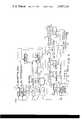
- FIG. 1is a block diagram illustrating the overall system broadly and the timing and interfacing at the central unit in detail.
- FIG. 2is a block diagram of the network central unit.
- FIG. 3is a block diagram of an illustrative one of the subscriber control units.
- FIG. 4illustrates a preferred allocation of frequencies in the broadband communication link.
- FIG. 5is a schematic block diagram of the apparatus comprising addressing and other timing decoders in the subscriber unit.
- FIG. 6is a schematic block diagram of the apparatus comprising control logic in the subscriber unit.
- FIG. 7is a block diagram of the alphanumeric electronics in an expanded subscriber unit.
- the overall system of the present inventionis seen to comprise a mini-computer 11, the speed and storage capacity of which is tailored to the size and complexity of services to be offered in a specific installation.
- the computercommunicates with typical input-output equipment 13 and by way of an interface unit 15 with the timing and encoding equipment of the central unit or so-called "head end" in a manner to be described in greater detail subsequently.
- the head endultimately supplies a broad band of radio frequency signals to a trunk line 17 which distributes those signals by a tree-organized wideband communication link such as a co-axial cable to a plurality of subscriber units each of which comprises a subscriber control unit 19 and a standard television receiver 21.
- the subscribermay have coupled to his subscriber control unit, a standard FM radio, keyboard input, or virtually any other input-output device desired.
- Each subscriber control unit 19counts time intervals and recognizes its own unique time-slot for duplex data messages. This structuring allows mode time-sharing for one of many service functions.
- Television frame related timing ratesare used to accomplish a uniform locked network clocked system which is referenced at the central unit to provide synchronism for television raster related services.
- a locked digitally clocked time-slot sequenceexists between the central unit and all of the subscriber units for an overall subscriber cycle time which is fixed, contiguous and repetitive. For example, 525 subscriber addresses exist in a standard television frame.
- Each subscriber control unitresponds to a specific unique clock counted time-slot which is permanently set in the subscriber control unit and allows for the transmission and reception of brief duplex control messages of, for example, 16 bits during that subscriber's time-slot.
- the control bit ratewould be 16 times the addressed clock rate of 15,734 cycles or 251.5 KHz.
- Each subscriber's addresswould thus correspond to a numbered horizontal raster line in one of, for example, 24 television frames to allow for 12,600 subscribers.
- the datamay be Manchester encoded onto a phase shift keyed modulated radio frequency carrier, the frequency of which is harmonically related to the control data rate, the time-slot rate and the system frame rate.
- the Manchester encoded dataform two equal energy side band spectrums about the virtual radio frequency pilot carrier and each subscriber terminal is provided with a phase locked receiver which tracks the virtual carrier to recover a 4.027 MHz clock signal which is divided down to the locked system clock rate of 251.5 KHz.
- the control data clock signal, address clock rate, and the field and frame ratesmay then be unambiguously obtained by binary divisions and data or system reset control of the binary counters.
- the digital modulationis separately extracted from the phase locked loop by side band demodulation and thus the data output is independent of the system clock rate and it is possible to run the data rate for digital terminal services at a higher rate than the 251.5 KHz system clock rate. This feature substantially enhances the system data handling capability.
- the upstream transmitterencodes subscriber terminal data at the same clock rate of 251.5 KHz and the upstream radio frequency carrier is clocked by the downstream clock rate to locate it in the upstream spectrum.
- the upstream control and data informationmay be phase or frequency shift key modulated about the upstream pilot signal.
- the cable networkhas many branches reaching into homes, complexes and various businesses and bi-directional signal distribution is accomplished by co-axial cable layouts of main trunks and feeder lines. Because of cable losses, the system may employ frequency selective line extender amplifiers to maintain uniform signal levels.
- the mini-computer 11may be asynchronous therewith with the computer interface 15 providing buffering between the computer and the remainder of the system.
- the television synchronization related timingis organized so that a subscriber time-slot corresponds to one horizontal line of the television raster; however, it could also be organized to relate to any multiple or submultiple number of horizontal lines. With a one horizontal line time-slot, the subscriber time-slot is approximately 64 microseconds in length. Under the assumption of 24 frames for each complete addressing cycle, 12,600 subscribers may be identified and one of these subscriber time-slots may be reserved for resetting all of the subscriber address counters by an exclusive, for example, 16 bit message from the central unit.
- studio equipment or an incoming network programwill provide a composite video signal on line 23 along with a horizontal sync reference signal on line 25 and a vertical sync reference signal on line 27.
- the horizontal sync reference signalis supplied to a time discriminator 24 which also receives a 15,734 Hz output signal from a phase locked loop.
- the loopcomprises the time discriminator 24, a low pass filter 27, a voltage controlled oscillator 29 and the several dividers 31, 33, and 35 along with their necessary counter reset connections which are coupled to block 37.
- the voltage controlled oscillator 29is controlled by the filtered time discriminator output or error signal and runs at a frequency which is 16 ⁇ 2 ⁇ 16 ⁇ 15,734 or actually 8.0558 MHz.
- This voltage controlled oscillator when multiplied by 14provides the 112 MHz downstream pilot frequency for the transmitter 39.
- a 0.5 MHz signalis provided from the first divider 31 for the Manchester encoding and phase shift keyed modulation of the pilot carrier by way of encoder 41.
- the next divide by 2 counter 33yields the 251.5 KHz bit rate for the digital data operations and the signal may also be used to interface the duplex data into and out of the mini-computer 11 whose operations are asynchronous with the remainder of the system and which may be organized for parallel word operations.
- the next divide by 16 counter 35provides an output for synchronizing the subscriber time-slot operations between the subscribers and the input synchronization reference signal.
- the vertical sync reference appearing on line 27is supplied to a frame field and master reset timing loop which operates in a manner similar to the previously discussed horizontal sync loop, however, without a voltage controlled oscillator. This loop operates to synchronize the interrelated timing requirements by programming of reset commands to the dividers 43 and 45.
- a data multiplexer 47receives digital data from the character data buffer 49, control data from the computer interface and various timing control signals to generate the downstream data output. This data is Manchester encoded in the encoder 41 for transmission to the subscribers. With an assumed 16 bit word message, the last time-slot in a subscriber cycle should contain a master reset message which sets all subscriber terminal counters to zero so that each can count up to its unique time-slot count.
- the first three 16 bit words coming from the program sequence generator 51may convey the encoding sequences employed for commutation or scrambling of the controlled access video programming and the following successive 16 bit time-slot messages convey control and data communication to successive subscribers and, for example, may include control data derived from computer routines resulting from an actual request by that subscriber during a previous cycle.
- the time-slotted subscriber cyclesare contiguous and continue for as long as the network is active.
- the subscriber unitWhen a control data message is sent to a subscriber during his time-slot, the subscriber unit is so equipped that the subscriber can respond concurrently during that same time-slot with, for example, a request data message.
- the contiguous data stream to all these subscribersis thus matched with a contiguous data stream arriving at the network central location from individual subscribers which is identified as upstream data.
- the radio frequency combiner 53is a frequency diplexer which combines multiple signal channels onto and from the cable. Incoming signals from this combiner are supplied to an FM receiver 55 which may, for example, receive a frequency shift keyed pilot carrier containing the upstream data.
- an FM receiver 55which may, for example, receive a frequency shift keyed pilot carrier containing the upstream data.
- the upstream signalis demodulated and decoded according to well known techniques in the data decoder 57, it is then distributed by way of the multiplexer circuit 59 which under control of the computer by way of computer interface 15 functions to route the upstream data to either the computer interface of the character data buffer 49 to be interfaced with further information systems such as display or additional input-output equipment.
- FIG. 2A more general view of the central unit will be found in FIG. 2 wherein reference numerals from FIG. 1 have been carried over to identify substantially identical units within the equipment.
- the FM upstream receiver identified as 56 in FIG. 2incorporates the functions of the data decoder 57 and multiplexer 59 of FIG. 1 for the sake of simplicity.
- the free and commercial television channelsare supplied to the radio frequency combiner 53 from the RF modulators 61 in known manner.
- premium baseband video, synchronizing signals, and soundare first modulated on individual intermediate frequency carriers in the IF modulators 63.
- the intermediate frequency carriers from modulators 63are commuted within each group of three and the commutated intermediate frequency carriers modulate three radio frequency modulators in the channel switching and RF modulators block 65.
- This scramblingmay, for example, occur by providing a first television program on one of the channels for a certain number of fields, then commuting this program to a second channel for another certain number of fields after which the program is commuted to yet the third channel for another certain number of fields after which the sequence is repeated.
- Two other television programswould, of course, similarly be stepped through each of the communication channels so that a normal television receiver receiving signals on one of these channels would see a few frames of one program followed by a few frames of the second and of the third programs, none of which would be of sufficient duration to be intelligible.
- the scrambling sequencemay be periodically changed by the head end computer.
- the timing generator 67uses the synchronizing signals from one of the premium program channels to reference all clocking and timing operations for the entire network including the synchronizing signals for the remaining premium and the free television signals.
- the output of the timing generator 67controls the encoding scrambling rate, the subscriber addressing, the message bit rate and references the two data modulated pilot carrier frequencies.
- the mini-computer 11performs network management and control functions for all the subscribers as well as for the head end. This involves a closed loop cycle of subscriber status monitoring, internal bookkeeping and data processing, and management of subscriber initiated messages by means of a control message to each subscriber. Time sharing processes are employed to perform different functions at different times. In addition to the network control functions, the mini-computer 11 computes premium program billing according to time and a program rate schedule, maintains the required accounting records, tabulates network loading when a program viewing analysis is desired, determines access to restricted programming and lists the addresses and reactions from those subscribers watching programs where preference polling responses were requested. This can, of course, be co-ordinated by way of the operator input-output equipment 13.
- the systemhas optional provision for the transmission for the transmission and reception of alphanumeric characters and in FIGS. 2 and 3 those blocks indicated in dotted lines such as the downstream and upstream character data buffers 49 are optional and may be employed when alphanumeric character transmission and display is desired.
- the subscriber control unit 19 of FIG. 1is the interface device between the CATV cable network and a subscriber's terminal equipment which in the simplest embodiment will be merely the subscriber's television receiver, however, in special applications it may interface with or be a part of dedicated data handling equipment for any of several special applications.
- a 12 button touch key control 69would be the only required subscriber input device and his TV receiver would be the only subscriber output device.
- Optional additional equipment illustrated in FIG. 3includes an alphanumeric keyboard input device 71 and a converter 73 for converting the seven TV super band channels illustrated in FIG. 4 to a frequency compatible with the television receiver.
- the subscriber control unit illustrated in the block diagram of FIG. 3has a phase shift keyed receiver 75 which operates as a coherent data receiver with a phase locked loop to recover the network clocking signal and to keep signal data in synchronism with the head end timing.
- the Manchester encoded data arriving from the network central unitis modulated on the 112 MHz pilot carrier and since this modulation is either a zero or a one, there is no actual signal at the carrier frequency and the data and clock signals exist totally in the two side bands about the absent carrier.
- the Manchester encoding processis a process where the basic information bit rate is converted to a signal at double that bit rate with, for example, a 1,0 pair representing a 1 and a 0,1 pair representing a 0 and is a digital data modulation technique which splits the data power spectrum equally among the upper and lower side bands thus allowing recovery of the virtual carrier.
- the phase locked loop receivertracks the virtual carrier narrow band fashion for transmission reliability and its output can then be used to reconstitute the 251.5 KHz clock signal which is the reference or synchronous TV related network timing.
- the phase locked loop detector outputrecovers the 8 MHz synchronous clock signal on line 77 which after division by 32 provides the digital data clocking signal.
- the digital signalitself is separately recovered from the same phase detector by way of a low pass 1 megacycle filter, for example, and that signal is then Manchester decoded to 251.5 KHz to convey the downstream digital communication data on line 79.
- a master reset decoder 81is employed in each subscriber control unit to reset all of the counters in that subscriber control unit upon the occurrence of a reset signal which as noted earlier, may be 16 consecutive ones in the last time-slot of a subscriber cycle.
- This master reset signaloperates to initialize the counter chain to zero by way of the input lines marked with a similar R to the four counter stages 83, 85, 87, and 89 and the old-new response latch 91.
- Each subscriberwill be assigned a unique time-slot and except for special data communication applications no two subscribers will have this same time-slot address.
- each subscriber control unitwill be preset to decode its time-slot, for example, by a number of switches or shorting jumpers in the decoder circuitry 93.
- the decoder circuitry 93according to one embodiment is shown.
- the binary signal contents of the individual cells of counters 85, 87, and 89specify the current time-slot which is equivalent to the subscriber unit address.
- the unique time slot or address associated with the subscriber unitis determined.
- the binary logic signals of the individual cells of counter 85are supplied to input terminals of logic AND gate 124 via lines 120 through 121; the binary logic signals of the individual cells of counter 87 are supplied to input terminals of logic AND gate 129; and the binary logic signals of the individual cells of counter 89 are applied to input terminals of logic AND gate 134.
- inverting amplifiers 122 through 123, 127 to 128 and 132 to 133can be employed.
- many countershave inverse signal terminals as well as direct signal terminals associated with individual counter cells, and the inverse signal terminals can be utilized in place of the inverting amplifiers.
- logic "1" signalswill appear at the output terminals of gates 124, 129, and 134.
- logic AND gate 135.When the predetermined address is in counters 85, 87, and 89, a valid address signal is applied to an output terminal of logic AND gate 135, allowing data to be exchanged between the subscriber unit and the head end equipment.
- Logic AND gate 140has applied to input terminals binary logic signals from preselected cells of buffer 97. These signals are applied to gate 140 via lines 136 through 137 and as with the addressing apparatus inverting amplifier 138 through 139 can be employed to establish the presence of a logic "0" in a cell of buffer 97 at an input terminal of gate 140. Buffer 97 can, in some applications, have an inverse signal terminal available for each buffer cell, obviating the need for inverting amplifiers 138 through 139. When the contents of the preselected buffer cells have preselected binary signals, a logic "1" signal is applied to an output terminal of gate 140 setting latch 141.
- the setting of latch 141causes a signal to be applied to register 142.
- register 142loads in the individual cells the contents of preestablished cells of the buffer register 97 via lines 143 through 144.
- the contents of the register 142can now be interpretted as a number.
- the output signal of latch 141is also applied to an input terminal of logic AND gate 145. Another input terminal of gate 145 is coupled to the clock signal.
- the clock signalis also applied to counter 147, and the counter 147 increments one count for each clock pulse.
- Comparator 148compares the contents of counter 147 with register 142. As long as the contents of the comparator and the register are not the same, a logic "0+ signal is applied to an output terminal coupled to an inverting amplifier 146.
- the output signal of the inverting amplifier 146is applied to an input terminal of gate 145.
- a valid address signalis applied to an output terminal of gate 145 when a positive clock pulse, a latch signal, and a logic "1" signal is available from inverting amplifier 146.
- a logic "1" signal at the output terminal of the comparatorresets latch 141 and register 142 and removes the valid address signal.
- switchesmight instead be a shift register which in addition to its normal preset address decoding could be signal controlled from the network central unit to line the subscriber control unit up with another subscriber control unit for long term controlled data communication.
- decoder circuitry 93which includes logic circuits with timing provided generally by the 251 KHz clock signal, supplies a valid address signal for the duration of a count in counters 85, 87, and 89 corresponding to the address of the subscriber control unit. That is, appropriate signals in counters 85, 87, and/or 89 are combined to produce a valid address signal.
- no address datais transmitted in the present system but rather every subscriber control unit is started counting by the master reset code and each identifies its own time-slot by having counted up to the prescribed predetermined value.
- Gate 95 in FIG. 3in response to a signal from the time-slot decoding circuitry 93, gates the 251 KHz clock signal to a pair of 16 bit data buffer registers 97 and 99 and basically identifies this particular subscriber control unit time-slot and causes the upstream data buffer 99 to transmit its contents by way of the frequency shift keyed transmitter 101 to the control unit and to accept the incoming information on line 79 into the downstream data buffer 97.
- the downstream messageis further adapted to announce entry of a new control message into the buffer 97 when a change of service has been requested. This accomplishes a latched service operation and makes muting for time-slot borrowing possible.
- the upstream data buffer 99collects subscriber request and control monitoring data which is transmitted during the proper subscriber time-slot of each subscriber cycle. When the message goes upstream the first bit thereof indicates the data as a new request or as an old status indication. The data is shifted out of the register 99 by the valid address gated clock signal which may also turn the transmitter 101 on.
- the controls associated with the subscriber control unitnormally consists of a twelve button touch key control 69.
- the apparatus controlling the messages transferred from the subscriber unit to the head end apparatusresides in the control logic 105 shown in FIG. 6.
- control logic 105shown in FIG. 6.
- error dataapplied to input data lines 150 through 151 of control logic 105
- vote requesti.e. status request data applied to input data lines 152 through 153 of control logic 105
- subscriber request dataapplied from touch key control 69 to input data lines 154 through 155 of control logic 105.
- the vote or status request linesare coupled to apparatus indicating the operating status of the subscriber unit.
- the error data linesare coupled to individual cells of the 16-bit downstream buffer register 97.
- control logic 105determines the format of data being transferred by the head end equipment, determined by control logic 105.
- Output lines 156 through 157 of control logic 105apply binary logic signals to associated cells of buffer 99 reserved for identifying code data specifying the nature of the accompanying message data;
- output lines 158 through 159 of control logic 105is applied binary signals to associated cells of buffer 99 at positions reserved for the message or information part of the transfer;
- output lines 160 through 161 of control logic 105apply binary signal to positions of buffer 99 reserved for error identification of information transferred from the subscriber unit to the head end unit.
- a positive logic "1" signalis applied to logic AND gate 176.
- a positive signalis thereafter applied by gate 176 to an input terminal of inverting amplifier 163, an input terminal of logic AND gate 165, a first input terminal of encoding apparatus 168 and two input terminals of logic AND gates 170 through 171.
- Input terminals of gates 170 through 171are coupled to input lines 150 through 151 respectively.
- a positive logic signal applied to gate 176applies a negative logic signal to input terminals of logic AND gate 177 and logic AND gate 162 thereby disabling those gates.
- the application of a logic signal to gates 170 through 171enables the application of error data carried by lines 150 through 151 to cell of buffer register 99 associated with output lines 158 through 159 and 160 through 161.
- the activation of the gate 176 by the parity diagnostic apparatushas the highest priority of the message types in the present embodiment.
- a positive logic signalis applied to an input terminal of logic AND gate 176.
- a second input terminal of gate 162receives a positive logic signal from the output terminal of inverting amplifier 163 unless there is a positive logic signal at the output terminal of gate 176.
- the output terminal of gate 177applies a positive logic signal to a second input terminal of encoding apparatus 168, an input terminal of inverting amplifier 164, an input terminal of logic AND gate 166 and input terminals of logic AND gates 172 through 173 respectively.
- Other input terminals of gates 172 through 173are coupled to input lines 152 through 153 to which status information is applied.
- a positive logic signal applied to the output terminal of gate 177causes the status data signals of input lines 152 through 153 to be applied to the cells of buffer register associated with output line 158 through 159.
- parity generating apparatus 169and the output terminals of parity apparatus 169 are coupled to output lines 160 through 161, which in turn are coupled to buffer register cells reserved for parity information.
- a positive logic signal from control 69is coupled, via logic AND gate 179, to an input terminal of logic AND gate 162.
- gate 179is activated only during a delay clock pulse, the clock pulse delayed by delay apparatus 178.
- the output terminals of gate 176 and gate 177are negative logic signals
- positive logic signalsare applied to the remaining input terminals of gate 162 via inverting amplifier 163 and inverting amplifier 164, and a positive logic signal is applied to an output terminal of gate 162.
- a positive logic signal at the output terminal of gate 162causes a positive logic signal to be applied to a third input terminal of encoding apparatus 168, an input terminal of gate 167 and input terminals of logic AND gates 174 through 175.
- the input terminal of encoding apparatus 168activated by gate 176, 177, or 162, activates binary signal apparatus of 168 for applying signals to selected cells identifying the nature of the data in buffer 99.
- gates 174 through 175are coupled to input lines 154 through 155 which are in turn coupled to output terminals of key control 69.
- a positive logic signal at an output terminal of gate 162causes binary signals from key control 69 to be applied to output lines 158 through 159 and ultimately to the message data cells of buffer register 99.
- the parity generating apparatus 169produces appropriate parity bits for inclusion in the register cells associated with output lines 160 through 161. To prevent continuous repetition of information, the input clock pulses are applied to input terminals of gates 165, 166, and 167.
- the output terminals of gates 165, 166, and 167return a binary signal to parity diagnostics apparatus 109, vote latch request 107, or key control 69, respectively, upon transmission of the data by the upstream buffer register 99 of the corresponding information the head end equipment. These binary signals indicate completion of the required data transmission.
- the vote latch request and parity diagnostic signalsare activated upon removal of the clock pulse from buffer register 97, no timing problems arise when the data is entered into the downstream buffer 97 once during every address cycle. For more frequent data reception by buffer 97, additional timing apparatus may be required to insure the integrity of the data transmitted from the upstream buffer register as will be clear to those skilled in the art.
- this control panelmay be replaced with the more complex 64 character control keyboard 71 in FIG. 7 to operate normal as well as alphanumeric services.
- the alphanumeric electronics 103would then have to be added to the subscriber control unit.
- the control logic circuitry 105which is analogous to but less complex than the alphanumeric electronics 103 will sense the operational status of the subscriber control unit such as an indication that the subscriber is viewing a premium program and will compose control functions for upstream request communications when the appropriate control keys are operated.
- the vote request latch and parity dignostics 107 and 109allow the central unit to interrogate a subscriber unit during one subscriber cycle and receive a response to that interrogation during the next subscriber cycle.
- the alphanumeric electronics 103includes a character generator 180, a memory 181, and a television field formatting and control apparatus 182. Signals from the head end equipment are entered in downstream data buffer register 97 and entered in television field formatting and control apparatus.
- the control apparatus 182provides a consistent format to video scenes displaying the incoming information and converts the incoming data signals in a manner suitable for controlling character generator 180. Under control of the control apparatus, character generator 180, utilizing the data stored in memory 181 provides a video display of the information.
- the control logic 105enters the data in the upstream data buffer.
- the alhanumeric data transmitted upstreamcan be stored in the memory.
- the communications from the head end equipment and the subscriber unitcan be simultaneously displayed on the video display.
- the upstream data to be communicated to the head end equipmentcan be stored and edited until the message is complete.
- the contents of the memorycan be transmitted continuously until the message is complete instead of utilizing the allotted address time slots.
- the premium decoding converter 113 of FIG. 3sequentially provides local oscillator signals of the appropriate frequency to track with a specified one of the premium programs.
- the sequence of frequencies requiredis provided by the sequence decode control unit 111 which as noted earlier may be periodically updated by a new code sequence transmitted from the control unit.
- This decoding sequenceis initialy supplied to the subscriber control unit from the central unit in response to a request entered on the manual control 69 for that particular program.
Landscapes
- Engineering & Computer Science (AREA)
- Multimedia (AREA)
- Signal Processing (AREA)
- Two-Way Televisions, Distribution Of Moving Picture Or The Like (AREA)
Abstract
Description
Claims (10)
Priority Applications (1)
| Application Number | Priority Date | Filing Date | Title |
|---|---|---|---|
| US05/522,795US3997718A (en) | 1973-02-01 | 1974-11-11 | Premium interactive communication system |
Applications Claiming Priority (2)
| Application Number | Priority Date | Filing Date | Title |
|---|---|---|---|
| US32881873A | 1973-02-01 | 1973-02-01 | |
| US05/522,795US3997718A (en) | 1973-02-01 | 1974-11-11 | Premium interactive communication system |
Related Parent Applications (1)
| Application Number | Title | Priority Date | Filing Date |
|---|---|---|---|
| US32881873AContinuation-In-Part | 1973-02-01 | 1973-02-01 |
Publications (1)
| Publication Number | Publication Date |
|---|---|
| US3997718Atrue US3997718A (en) | 1976-12-14 |
Family
ID=26986528
Family Applications (1)
| Application Number | Title | Priority Date | Filing Date |
|---|---|---|---|
| US05/522,795Expired - LifetimeUS3997718A (en) | 1973-02-01 | 1974-11-11 | Premium interactive communication system |
Country Status (1)
| Country | Link |
|---|---|
| US (1) | US3997718A (en) |
Cited By (94)
| Publication number | Priority date | Publication date | Assignee | Title |
|---|---|---|---|---|
| US4041398A (en)* | 1976-06-03 | 1977-08-09 | Icc, Inc. | Bi-directional digital communication network |
| US4090220A (en)* | 1974-07-10 | 1978-05-16 | Communications Patents Limited | Wired broadcasting systems for processing coded data representative of subscriber station conditions |
| FR2466157A1 (en)* | 1979-09-26 | 1981-03-27 | Pioneer Electronic Corp | METHOD FOR RECEIVING A CHANNEL IN A CABLE TELEVISION BROADCAST SET |
| FR2483718A1 (en)* | 1980-05-30 | 1981-12-04 | Pioneer Electronic Corp | PASSIVE DATA CONTROL CIRCUIT, CALL CONFIGURATION GENERATOR CIRCUIT, AND TERMINAL VERIFICATION CIRCUIT FOR CAB TELEVISION SYSTEM |
| US4323921A (en)* | 1979-02-06 | 1982-04-06 | Etablissement Public De Diffusion Dit "Telediffusion De France" | System for transmitting information provided with means for controlling access to the information transmitted |
| US4331973A (en)* | 1980-10-21 | 1982-05-25 | Iri, Inc. | Panelist response scanning system |
| US4331974A (en)* | 1980-10-21 | 1982-05-25 | Iri, Inc. | Cable television with controlled signal substitution |
| US4337483A (en)* | 1979-02-06 | 1982-06-29 | Etablissement Public De Diffusion Dit "Telediffusion De France" | Text video-transmission system provided with means for controlling access to the information |
| US4343042A (en)* | 1979-07-10 | 1982-08-03 | Cablebus Systems Corporation | Bi-directional data transmission and control system |
| US4346263A (en)* | 1980-01-14 | 1982-08-24 | Badger Meter, Inc. | Signalling arrangement for telephone equipment |
| US4354201A (en)* | 1979-06-15 | 1982-10-12 | Etablissement Public De Diffusion Dit: Telediffusion De France | Television system with access control |
| US4365267A (en)* | 1980-05-30 | 1982-12-21 | Pioneer Electronic Corporation | Passive data monitor for use with polling pattern generator in CATV system |
| EP0079150A1 (en)* | 1981-11-02 | 1983-05-18 | Wang Laboratories Inc. | Data communication system with increased effective bandwidth |
| US4385314A (en)* | 1980-05-30 | 1983-05-24 | Pioneer Electronic Corporation | Polling pattern generator for CATV system |
| US4404589A (en)* | 1980-10-21 | 1983-09-13 | Iri, Inc. | Cable television with multi-event signal substitution |
| US4434436A (en) | 1981-07-13 | 1984-02-28 | Bruce Merrill | Addressable premium channel obfuscation device for cable television systems |
| US4455570A (en)* | 1980-10-13 | 1984-06-19 | Pioneer Electronic Corporation | CATV System |
| FR2539571A1 (en)* | 1983-01-17 | 1984-07-20 | Austin Jean Luc | Teledistribution automatic billing and management system |
| WO1985002744A1 (en)* | 1983-12-09 | 1985-06-20 | Zenith Electronics Corporation | Peak load access in a two-way catv contention system |
| US4533948A (en)* | 1982-04-30 | 1985-08-06 | General Instrument Corporation | CATV Communication system |
| US4538174A (en)* | 1982-03-11 | 1985-08-27 | Communications Patents Limited | Two-way subscriber TV system with multiple subscriber's sets |
| US4553161A (en)* | 1983-12-09 | 1985-11-12 | Zenith Electronics Corporation | Upstream data packet time slot synchronization with downstream VBI for two-way CATV system |
| US4567511A (en)* | 1983-05-25 | 1986-01-28 | Agb Research Plc | Transmitting and storing data relating to television viewing |
| US4591906A (en)* | 1986-02-12 | 1986-05-27 | Morales Garza Fernando | Wireless transmission from the television set to the television station |
| US4613901A (en)* | 1983-05-27 | 1986-09-23 | M/A-Com Linkabit, Inc. | Signal encryption and distribution system for controlling scrambling and selective remote descrambling of television signals |
| US4633462A (en)* | 1983-07-18 | 1986-12-30 | The Board Of Trustees Of The University Of Illinois | Multiple access communication on a CATV reverse channel |
| US4684981A (en)* | 1983-11-09 | 1987-08-04 | Sony Corporation | Digital terminal address transmitting for CATV |
| US4712238A (en)* | 1984-06-08 | 1987-12-08 | M/A-Com Government Systems, Inc. | Selective-subscription descrambling |
| US4755871A (en)* | 1986-11-25 | 1988-07-05 | Magus, Ltd. | Control of rf answer pulses in a TV answer back system |
| US4761684A (en)* | 1986-11-14 | 1988-08-02 | Video Jukebox Network | Telephone access display system |
| US4835604A (en)* | 1987-02-23 | 1989-05-30 | Sony Corporation | Aircraft service system with a central control system for attendant call lights and passenger reading lights |
| US4866515A (en)* | 1987-01-30 | 1989-09-12 | Sony Corporation | Passenger service and entertainment system for supplying frequency-multiplexed video, audio, and television game software signals to passenger seat terminals |
| US4887152A (en)* | 1987-01-30 | 1989-12-12 | Sony Corporation | Message delivery system operable in an override mode upon reception of a command signal |
| US4896209A (en)* | 1987-02-10 | 1990-01-23 | Sony Corporation | Passenger vehicle polling system having a central unit for polling passenger seat terminal units |
| US4897714A (en)* | 1987-02-25 | 1990-01-30 | Sony Corporation | Passenger vehicle service system |
| USRE33189E (en)* | 1981-11-19 | 1990-03-27 | Communications Satellite Corporation | Security system for SSTV encryption |
| US4958381A (en)* | 1987-02-17 | 1990-09-18 | Sony Corporation | Two way communication system |
| US4994908A (en)* | 1988-12-23 | 1991-02-19 | Scientific-Atlanta, Inc. | Interactive room status/time information system |
| US5001554A (en)* | 1988-12-23 | 1991-03-19 | Scientific-Atlanta, Inc. | Terminal authorization method |
| US5077607A (en)* | 1988-12-23 | 1991-12-31 | Scientific-Atlanta, Inc. | Cable television transaction terminal |
| USRE33808E (en)* | 1980-10-21 | 1992-01-28 | Information Resources, Inc. | Cable television with multi-event signal substitution |
| US5089885A (en)* | 1986-11-14 | 1992-02-18 | Video Jukebox Network, Inc. | Telephone access display system with remote monitoring |
| US5233652A (en)* | 1991-02-19 | 1993-08-03 | At&T Bell Laboratories | Selective off-premises jamming for premium CATV service |
| WO1993026129A1 (en)* | 1992-06-10 | 1993-12-23 | Scientific-Atlanta, Inc. | Diagnostic method and apparatus for a cable television interdiction system |
| US5309564A (en)* | 1992-03-19 | 1994-05-03 | Bradley Graham C | Apparatus for networking computers for multimedia applications |
| US5335277A (en)* | 1981-11-03 | 1994-08-02 | The Personalized Mass Media Corporation | Signal processing appparatus and methods |
| US5389964A (en)* | 1992-12-30 | 1995-02-14 | Information Resources, Inc. | Broadcast channel substitution method and apparatus |
| US5428606A (en)* | 1993-06-30 | 1995-06-27 | Moskowitz; Scott A. | Digital information commodities exchange |
| US5559803A (en)* | 1994-06-28 | 1996-09-24 | Kokusai Denshin Denwa Co., Ltd. | Communication system using a bidirectional tree structure network |
| US5579057A (en)* | 1993-06-07 | 1996-11-26 | Scientific-Atlanta, Inc. | Display system for selectively overlaying symbols and graphics onto a video signal |
| US5667440A (en)* | 1993-12-28 | 1997-09-16 | Pioneer Electronic Corporation | Bidirectional communication system |
| US6014439A (en)* | 1997-04-08 | 2000-01-11 | Walker Asset Management Limited Partnership | Method and apparatus for entertaining callers in a queue |
| US6034678A (en)* | 1991-09-10 | 2000-03-07 | Ictv, Inc. | Cable television system with remote interactive processor |
| US6055315A (en)* | 1997-12-09 | 2000-04-25 | Ictv, Inc. | Distributed scrambling method and system |
| US6064377A (en)* | 1990-09-28 | 2000-05-16 | Ictv, Inc. | Subscriber directed simultaneous multiple signal presentation for interactive cable television system |
| USRE36988E (en)* | 1988-12-23 | 2000-12-12 | Scientific-Atlanta, Inc. | Terminal authorization method |
| US6166728A (en)* | 1992-12-02 | 2000-12-26 | Scientific-Atlanta, Inc. | Display system with programmable display parameters |
| US6305020B1 (en) | 1995-11-01 | 2001-10-16 | Ictv, Inc. | System manager and hypertext control interface for interactive cable television system |
| US20020067823A1 (en)* | 1997-04-08 | 2002-06-06 | Walker Jay S. | Method and apparatus for entertaining callers in a queue |
| US6430530B1 (en)* | 1999-09-16 | 2002-08-06 | Oak Technology, Inc. | Apparatus for automatically processing both encoded and unencoded data |
| US6499027B1 (en) | 1998-05-26 | 2002-12-24 | Rockwell Collins, Inc. | System software architecture for a passenger entertainment system, method and article of manufacture |
| US6782392B1 (en) | 1998-05-26 | 2004-08-24 | Rockwell Collins, Inc. | System software architecture for a passenger entertainment system, method and article of manufacture |
| US6807538B1 (en) | 1998-05-26 | 2004-10-19 | Rockwell Collins | Passenger entertainment system, method and article of manufacture employing object oriented system software |
| US6813777B1 (en) | 1998-05-26 | 2004-11-02 | Rockwell Collins | Transaction dispatcher for a passenger entertainment system, method and article of manufacture |
| US6938258B1 (en) | 1998-05-26 | 2005-08-30 | Rockwell Collins | Message processor for a passenger entertainment system, method and article of manufacture |
| US6941573B1 (en) | 1996-08-07 | 2005-09-06 | Information Resources, Inc. | Television distribution system for signal substitution |
| US7028304B1 (en) | 1998-05-26 | 2006-04-11 | Rockwell Collins | Virtual line replaceable unit for a passenger entertainment system, method and article of manufacture |
| US7124426B1 (en) | 1997-04-16 | 2006-10-17 | News Datacom Limited | Entertainment system |
| US20070011717A1 (en)* | 2005-07-06 | 2007-01-11 | Lauder Gary M | Distribution of interactive information content within a plurality of disparate distribution networks |
| US20070028288A1 (en)* | 2005-07-26 | 2007-02-01 | Sigmon Robert B Jr | System and method for providing video content associated with a source image to a television in a communication network |
| US20070028278A1 (en)* | 2005-07-27 | 2007-02-01 | Sigmon Robert B Jr | System and method for providing pre-encoded audio content to a television in a communications network |
| US7437749B1 (en)* | 1988-12-23 | 2008-10-14 | Scientific-Atlanta, Inc. | Interactive subscription television terminal |
| US20090302629A1 (en)* | 2006-09-06 | 2009-12-10 | Rydstroem Lars | Mechanical tailgate |
| US7697927B1 (en) | 2005-01-25 | 2010-04-13 | Embarq Holdings Company, Llc | Multi-campus mobile management system for wirelessly controlling systems of a facility |
| US7765573B1 (en) | 2005-03-08 | 2010-07-27 | Embarq Holdings Company, LLP | IP-based scheduling and control of digital video content delivery |
| US7769344B1 (en) | 1981-11-03 | 2010-08-03 | Personalized Media Communications, Llc | Signal processing apparatus and methods |
| US7786891B2 (en) | 2004-08-27 | 2010-08-31 | Embarq Holdings Company, Llc | System and method for an interactive security system for a home |
| US7840984B1 (en)* | 2004-03-17 | 2010-11-23 | Embarq Holdings Company, Llc | Media administering system and method |
| US7840982B1 (en) | 2004-09-28 | 2010-11-23 | Embarq Holding Company, Llc | Video-all call system and method for a facility |
| US8237551B2 (en) | 2008-04-30 | 2012-08-07 | Centurylink Intellectual Property Llc | System and method for in-patient telephony |
| US9021541B2 (en) | 2010-10-14 | 2015-04-28 | Activevideo Networks, Inc. | Streaming digital video between video devices using a cable television system |
| US9042454B2 (en) | 2007-01-12 | 2015-05-26 | Activevideo Networks, Inc. | Interactive encoded content system including object models for viewing on a remote device |
| US9123084B2 (en) | 2012-04-12 | 2015-09-01 | Activevideo Networks, Inc. | Graphical application integration with MPEG objects |
| US9204203B2 (en) | 2011-04-07 | 2015-12-01 | Activevideo Networks, Inc. | Reduction of latency in video distribution networks using adaptive bit rates |
| US9219922B2 (en) | 2013-06-06 | 2015-12-22 | Activevideo Networks, Inc. | System and method for exploiting scene graph information in construction of an encoded video sequence |
| US9294785B2 (en) | 2013-06-06 | 2016-03-22 | Activevideo Networks, Inc. | System and method for exploiting scene graph information in construction of an encoded video sequence |
| US9326047B2 (en) | 2013-06-06 | 2016-04-26 | Activevideo Networks, Inc. | Overlay rendering of user interface onto source video |
| US9635408B2 (en) | 1999-09-21 | 2017-04-25 | Quantum Stream Inc. | Content distribution system and method |
| US9788029B2 (en) | 2014-04-25 | 2017-10-10 | Activevideo Networks, Inc. | Intelligent multiplexing using class-based, multi-dimensioned decision logic for managed networks |
| US9800945B2 (en) | 2012-04-03 | 2017-10-24 | Activevideo Networks, Inc. | Class-based intelligent multiplexing over unmanaged networks |
| US9826197B2 (en) | 2007-01-12 | 2017-11-21 | Activevideo Networks, Inc. | Providing television broadcasts over a managed network and interactive content over an unmanaged network to a client device |
| US10275128B2 (en) | 2013-03-15 | 2019-04-30 | Activevideo Networks, Inc. | Multiple-mode system and method for providing user selectable video content |
| US10409445B2 (en) | 2012-01-09 | 2019-09-10 | Activevideo Networks, Inc. | Rendering of an interactive lean-backward user interface on a television |
| USRE47642E1 (en) | 1981-11-03 | 2019-10-08 | Personalized Media Communications LLC | Signal processing apparatus and methods |
Citations (10)
| Publication number | Priority date | Publication date | Assignee | Title |
|---|---|---|---|---|
| US3268814A (en)* | 1963-06-03 | 1966-08-23 | Lab For Electronics Inc | Plural carrier frequency telemetry and control system using pulse width modulation |
| US3396232A (en)* | 1964-07-01 | 1968-08-06 | Zenith Radio Corp | Interrogating system for subscription television receivers |
| US3647976A (en)* | 1970-03-09 | 1972-03-07 | Minnesota Mining & Mfg | Time-sharing subscriber communications system |
| US3651403A (en)* | 1970-05-18 | 1972-03-21 | Jerrold Electronics Corp | Simultaneous sweep testing system for catv |
| US3668307A (en)* | 1970-03-30 | 1972-06-06 | Kms Ind Inc | Two-way community antenna television system |
| US3676580A (en)* | 1970-06-01 | 1972-07-11 | Video Information Systems | Interrogated transponder system |
| US3730988A (en)* | 1970-07-29 | 1973-05-01 | Pioneer Electronic Corp | Electronic transmission system of static picture writings |
| US3743767A (en)* | 1971-10-04 | 1973-07-03 | Univ Illinois | Transmitter and receiver for the transmission of digital data over standard television channels |
| US3836888A (en)* | 1972-05-22 | 1974-09-17 | C Boenke | Variable message length data acquisition and retrieval system and method using two-way coaxial cable |
| US3882392A (en)* | 1973-01-29 | 1975-05-06 | Oak Industries Inc | Hotel-motel pay TV system |
- 1974
- 1974-11-11USUS05/522,795patent/US3997718A/ennot_activeExpired - Lifetime
Patent Citations (10)
| Publication number | Priority date | Publication date | Assignee | Title |
|---|---|---|---|---|
| US3268814A (en)* | 1963-06-03 | 1966-08-23 | Lab For Electronics Inc | Plural carrier frequency telemetry and control system using pulse width modulation |
| US3396232A (en)* | 1964-07-01 | 1968-08-06 | Zenith Radio Corp | Interrogating system for subscription television receivers |
| US3647976A (en)* | 1970-03-09 | 1972-03-07 | Minnesota Mining & Mfg | Time-sharing subscriber communications system |
| US3668307A (en)* | 1970-03-30 | 1972-06-06 | Kms Ind Inc | Two-way community antenna television system |
| US3651403A (en)* | 1970-05-18 | 1972-03-21 | Jerrold Electronics Corp | Simultaneous sweep testing system for catv |
| US3676580A (en)* | 1970-06-01 | 1972-07-11 | Video Information Systems | Interrogated transponder system |
| US3730988A (en)* | 1970-07-29 | 1973-05-01 | Pioneer Electronic Corp | Electronic transmission system of static picture writings |
| US3743767A (en)* | 1971-10-04 | 1973-07-03 | Univ Illinois | Transmitter and receiver for the transmission of digital data over standard television channels |
| US3836888A (en)* | 1972-05-22 | 1974-09-17 | C Boenke | Variable message length data acquisition and retrieval system and method using two-way coaxial cable |
| US3882392A (en)* | 1973-01-29 | 1975-05-06 | Oak Industries Inc | Hotel-motel pay TV system |
Cited By (215)
| Publication number | Priority date | Publication date | Assignee | Title |
|---|---|---|---|---|
| US4090220A (en)* | 1974-07-10 | 1978-05-16 | Communications Patents Limited | Wired broadcasting systems for processing coded data representative of subscriber station conditions |
| US4041398A (en)* | 1976-06-03 | 1977-08-09 | Icc, Inc. | Bi-directional digital communication network |
| US4337483A (en)* | 1979-02-06 | 1982-06-29 | Etablissement Public De Diffusion Dit "Telediffusion De France" | Text video-transmission system provided with means for controlling access to the information |
| US4323921A (en)* | 1979-02-06 | 1982-04-06 | Etablissement Public De Diffusion Dit "Telediffusion De France" | System for transmitting information provided with means for controlling access to the information transmitted |
| US4354201A (en)* | 1979-06-15 | 1982-10-12 | Etablissement Public De Diffusion Dit: Telediffusion De France | Television system with access control |
| US4343042A (en)* | 1979-07-10 | 1982-08-03 | Cablebus Systems Corporation | Bi-directional data transmission and control system |
| FR2466157A1 (en)* | 1979-09-26 | 1981-03-27 | Pioneer Electronic Corp | METHOD FOR RECEIVING A CHANNEL IN A CABLE TELEVISION BROADCAST SET |
| US4346263A (en)* | 1980-01-14 | 1982-08-24 | Badger Meter, Inc. | Signalling arrangement for telephone equipment |
| FR2483718A1 (en)* | 1980-05-30 | 1981-12-04 | Pioneer Electronic Corp | PASSIVE DATA CONTROL CIRCUIT, CALL CONFIGURATION GENERATOR CIRCUIT, AND TERMINAL VERIFICATION CIRCUIT FOR CAB TELEVISION SYSTEM |
| US4365267A (en)* | 1980-05-30 | 1982-12-21 | Pioneer Electronic Corporation | Passive data monitor for use with polling pattern generator in CATV system |
| US4385314A (en)* | 1980-05-30 | 1983-05-24 | Pioneer Electronic Corporation | Polling pattern generator for CATV system |
| US4455570A (en)* | 1980-10-13 | 1984-06-19 | Pioneer Electronic Corporation | CATV System |
| US4331973A (en)* | 1980-10-21 | 1982-05-25 | Iri, Inc. | Panelist response scanning system |
| USRE33808E (en)* | 1980-10-21 | 1992-01-28 | Information Resources, Inc. | Cable television with multi-event signal substitution |
| US4404589A (en)* | 1980-10-21 | 1983-09-13 | Iri, Inc. | Cable television with multi-event signal substitution |
| US4331974A (en)* | 1980-10-21 | 1982-05-25 | Iri, Inc. | Cable television with controlled signal substitution |
| US4434436A (en) | 1981-07-13 | 1984-02-28 | Bruce Merrill | Addressable premium channel obfuscation device for cable television systems |
| US9043859B1 (en) | 1981-11-02 | 2015-05-26 | Personalized Media Communications, Llc | Signal processing apparatus and methods |
| EP0079150A1 (en)* | 1981-11-02 | 1983-05-18 | Wang Laboratories Inc. | Data communication system with increased effective bandwidth |
| US8613034B1 (en) | 1981-11-03 | 2013-12-17 | Personalized Media Communications, Llc | Signal processing apparatus and methods |
| US8839293B1 (en) | 1981-11-03 | 2014-09-16 | Personalized Media Communications, Llc | Signal processing apparatus and methods |
| US8635644B1 (en) | 1981-11-03 | 2014-01-21 | Personalized Media Communications LLC | Signal processing apparatus and methods |
| US7830925B1 (en) | 1981-11-03 | 2010-11-09 | Personalized Media Communications, Llc | Signal processing apparatus and methods |
| US8621547B1 (en) | 1981-11-03 | 2013-12-31 | Personalized Media Communications, Llc | Signal processing apparatus and methods |
| US8646001B1 (en) | 1981-11-03 | 2014-02-04 | Personalized Media Communications, Llc | Signal processing apparatus and methods |
| US8607296B1 (en) | 1981-11-03 | 2013-12-10 | Personalized Media Communications LLC | Signal processing apparatus and methods |
| US8601528B1 (en) | 1981-11-03 | 2013-12-03 | Personalized Media Communications, L.L.C. | Signal processing apparatus and methods |
| US8587720B1 (en) | 1981-11-03 | 2013-11-19 | Personalized Media Communications LLC | Signal processing apparatus and methods |
| US8584162B1 (en) | 1981-11-03 | 2013-11-12 | Personalized Media Communications LLC | Signal processing apparatus and methods |
| US8572671B1 (en) | 1981-11-03 | 2013-10-29 | Personalized Media Communications LLC | Signal processing apparatus and methods |
| US8566868B1 (en) | 1981-11-03 | 2013-10-22 | Personalized Media Communications, L.L.C. | Signal processing apparatus and methods |
| US8558950B1 (en) | 1981-11-03 | 2013-10-15 | Personalized Media Communications LLC | Signal processing apparatus and methods |
| US8559635B1 (en) | 1981-11-03 | 2013-10-15 | Personalized Media Communications, L.L.C. | Signal processing apparatus and methods |
| US8555310B1 (en) | 1981-11-03 | 2013-10-08 | Personalized Media Communications, Llc | Signal processing apparatus and methods |
| US8395707B1 (en) | 1981-11-03 | 2013-03-12 | Personalized Media Communications LLC | Signal processing apparatus and methods |
| US8675775B1 (en) | 1981-11-03 | 2014-03-18 | Personalized Media Communications, Llc | Signal processing apparatus and methods |
| US8191091B1 (en) | 1981-11-03 | 2012-05-29 | Personalized Media Communications, Llc | Signal processing apparatus and methods |
| US8112782B1 (en) | 1981-11-03 | 2012-02-07 | Personalized Media Communications, Llc | Signal processing apparatus and methods |
| US8683539B1 (en) | 1981-11-03 | 2014-03-25 | Personalized Media Communications, Llc | Signal processing apparatus and methods |
| US8060903B1 (en) | 1981-11-03 | 2011-11-15 | Personalized Media PMC Communications, L.L.C. | Signal processing apparatus and methods |
| US8046791B1 (en) | 1981-11-03 | 2011-10-25 | Personalized Media Communications, Llc | Signal processing apparatus and methods |
| US7992169B1 (en) | 1981-11-03 | 2011-08-02 | Personalized Media Communications LLC | Signal processing apparatus and methods |
| US7953223B1 (en) | 1981-11-03 | 2011-05-31 | Personalized Media Communications, L.L.C. | Signal processing apparatus and methods |
| US7940931B1 (en) | 1981-11-03 | 2011-05-10 | Personalized Media Communications LLC | Signal processing apparatus and methods |
| US7926084B1 (en) | 1981-11-03 | 2011-04-12 | Personalized Media Communications LLC | Signal processing apparatus and methods |
| US7908638B1 (en) | 1981-11-03 | 2011-03-15 | Personalized Media Communications LLC | Signal processing apparatus and methods |
| US7889865B1 (en) | 1981-11-03 | 2011-02-15 | Personalized Media Communications, L.L.C. | Signal processing apparatus and methods |
| US7870581B1 (en) | 1981-11-03 | 2011-01-11 | Personalized Media Communications, Llc | Signal processing apparatus and methods |
| US5335277A (en)* | 1981-11-03 | 1994-08-02 | The Personalized Mass Media Corporation | Signal processing appparatus and methods |
| US7864956B1 (en) | 1981-11-03 | 2011-01-04 | Personalized Media Communications, Llc | Signal processing apparatus and methods |
| US7864248B1 (en) | 1981-11-03 | 2011-01-04 | Personalized Media Communications, Llc | Signal processing apparatus and methods |
| US7865920B1 (en) | 1981-11-03 | 2011-01-04 | Personalized Media Communications LLC | Signal processing apparatus and methods |
| USRE48682E1 (en) | 1981-11-03 | 2021-08-10 | Personalized Media Communications LLC | Providing subscriber specific content in a network |
| US7861278B1 (en) | 1981-11-03 | 2010-12-28 | Personalized Media Communications, Llc | Signal processing apparatus and methods |
| US7831204B1 (en) | 1981-11-03 | 2010-11-09 | Personalized Media Communications, Llc | Signal processing apparatus and methods |
| US5887243A (en) | 1981-11-03 | 1999-03-23 | Personalized Media Communications, L.L.C. | Signal processing apparatus and methods |
| USRE48633E1 (en) | 1981-11-03 | 2021-07-06 | Personalized Media Communications LLC | Reprogramming of a programmable device of a specific version |
| US7861263B1 (en) | 1981-11-03 | 2010-12-28 | Personalized Media Communications, Llc | Signal processing apparatus and methods |
| USRE48565E1 (en) | 1981-11-03 | 2021-05-18 | Personalized Media Communications LLC | Providing a subscriber specific solution in a computer network |
| US7860131B1 (en) | 1981-11-03 | 2010-12-28 | Personalized Media Communications, Llc | Signal processing apparatus and methods |
| US7860249B1 (en) | 1981-11-03 | 2010-12-28 | Personalized Media Communications LLC | Signal processing apparatus and methods |
| US7856649B1 (en) | 1981-11-03 | 2010-12-21 | Personalized Media Communications, Llc | Signal processing apparatus and methods |
| US7856650B1 (en) | 1981-11-03 | 2010-12-21 | Personalized Media Communications, Llc | Signal processing apparatus and methods |
| USRE48484E1 (en) | 1981-11-03 | 2021-03-23 | Personalized Media Communications, Llc | Signal processing apparatus and methods |
| US10715835B1 (en) | 1981-11-03 | 2020-07-14 | John Christopher Harvey | Signal processing apparatus and methods |
| USRE47968E1 (en) | 1981-11-03 | 2020-04-28 | Personalized Media Communications LLC | Signal processing apparatus and methods |
| US10616638B1 (en) | 1981-11-03 | 2020-04-07 | Personalized Media Communications LLC | Signal processing apparatus and methods |
| US7836480B1 (en) | 1981-11-03 | 2010-11-16 | Personalized Media Communications, Llc | Signal processing apparatus and methods |
| US10609425B1 (en) | 1981-11-03 | 2020-03-31 | Personalized Media Communications, L.L.C. | Signal processing apparatus and methods |
| USRE47867E1 (en) | 1981-11-03 | 2020-02-18 | Personalized Media Communications LLC | Signal processing apparatus and methods |
| US10523350B1 (en) | 1981-11-03 | 2019-12-31 | Personalized Media Communications LLC | Signal processing apparatus and methods |
| USRE47642E1 (en) | 1981-11-03 | 2019-10-08 | Personalized Media Communications LLC | Signal processing apparatus and methods |
| US10334292B1 (en) | 1981-11-03 | 2019-06-25 | Personalized Media Communications LLC | Signal processing apparatus and methods |
| US9674560B1 (en) | 1981-11-03 | 2017-06-06 | Personalized Media Communications LLC | Signal processing apparatus and methods |
| US9294205B1 (en) | 1981-11-03 | 2016-03-22 | Personalized Media Communications LLC | Signal processing apparatus and methods |
| US9210370B1 (en) | 1981-11-03 | 2015-12-08 | Personalized Media Communications LLC | Signal processing apparatus and methods |
| US7849493B1 (en) | 1981-11-03 | 2010-12-07 | Personalized Media Communications, Llc | Signal processing apparatus and methods |
| US9038124B1 (en) | 1981-11-03 | 2015-05-19 | Personalized Media Communications, Llc | Signal processing apparatus and methods |
| US8973034B1 (en) | 1981-11-03 | 2015-03-03 | Personalized Media Communications LLC | Signal processing apparatus and methods |
| US8914825B1 (en) | 1981-11-03 | 2014-12-16 | Personalized Media Communications LLC | Signal processing apparatus and methods |
| US8893177B1 (en) | 1981-11-03 | 2014-11-18 | {Personalized Media Communications, LLC | Signal processing apparatus and methods |
| US8869229B1 (en) | 1981-11-03 | 2014-10-21 | Personalized Media Communications, Llc | Signal processing apparatus and methods |
| US7849480B1 (en) | 1981-11-03 | 2010-12-07 | Personalized Media Communications LLC | Signal processing apparatus and methods |
| US8869228B1 (en) | 1981-11-03 | 2014-10-21 | Personalized Media Communications, Llc | Signal processing apparatus and methods |
| US8843988B1 (en) | 1981-11-03 | 2014-09-23 | Personalized Media Communications, Llc | Signal processing apparatus and methods |
| US7734251B1 (en) | 1981-11-03 | 2010-06-08 | Personalized Media Communications, Llc | Signal processing apparatus and methods |
| US7747217B1 (en) | 1981-11-03 | 2010-06-29 | Personalized Media Communications, Llc | Signal processing apparatus and methods |
| US7752650B1 (en) | 1981-11-03 | 2010-07-06 | Personalized Media Communications, Llc | Signal processing apparatus and methods |
| US7752649B1 (en) | 1981-11-03 | 2010-07-06 | Personalized Media Communications, Llc | Signal processing apparatus and methods |
| US7761890B1 (en) | 1981-11-03 | 2010-07-20 | Personalized Media Communications, Llc | Signal processing apparatus and methods |
| US8640184B1 (en) | 1981-11-03 | 2014-01-28 | Personalized Media Communications, Llc | Signal processing apparatus and methods |
| US8804727B1 (en) | 1981-11-03 | 2014-08-12 | Personalized Media Communications, Llc | Signal processing apparatus and methods |
| US7764685B1 (en) | 1981-11-03 | 2010-07-27 | Personalized Media Communications, L.L.C. | Signal processing apparatus and methods |
| US7769170B1 (en) | 1981-11-03 | 2010-08-03 | Personalized Media Communications, Llc | Signal processing apparatus and methods |
| US7769344B1 (en) | 1981-11-03 | 2010-08-03 | Personalized Media Communications, Llc | Signal processing apparatus and methods |
| US7774809B1 (en) | 1981-11-03 | 2010-08-10 | Personalized Media Communications, Llc | Signal processing apparatus and method |
| US7783252B1 (en) | 1981-11-03 | 2010-08-24 | Personalized Media Communications, Llc | Signal processing apparatus and methods |
| US7784082B1 (en) | 1981-11-03 | 2010-08-24 | Personalized Media Communications, Llc | Signal processing apparatus and methods |
| US8752088B1 (en) | 1981-11-03 | 2014-06-10 | Personalized Media Communications LLC | Signal processing apparatus and methods |
| US7793332B1 (en) | 1981-11-03 | 2010-09-07 | Personalized Media Communications, Llc | Signal processing apparatus and methods |
| US7797717B1 (en) | 1981-11-03 | 2010-09-14 | Personalized Media Communications, Llc | Signal processing apparatus and methods |
| US7801304B1 (en) | 1981-11-03 | 2010-09-21 | Personalized Media Communications, Llc | Signal processing apparatus and methods |
| US7805738B1 (en) | 1981-11-03 | 2010-09-28 | Personalized Media Communications, Llc | Signal processing apparatus and methods |
| US7805748B1 (en) | 1981-11-03 | 2010-09-28 | Personalized Media Communications, Llc | Signal processing apparatus and methods |
| US7805749B1 (en) | 1981-11-03 | 2010-09-28 | Personalized Media Communications, Llc | Signal processing apparatus and methods |
| US7810115B1 (en) | 1981-11-03 | 2010-10-05 | Personalized Media Communications, Llc | Signal processing apparatus and methods |
| US7814526B1 (en) | 1981-11-03 | 2010-10-12 | Personalized Media Communications, Llc | Signal processing apparatus and methods |
| US7818761B1 (en) | 1981-11-03 | 2010-10-19 | Personalized Media Communications, Llc | Signal processing apparatus and methods |
| US7818777B1 (en) | 1981-11-03 | 2010-10-19 | Personalized Media Communications, Llc | Signal processing apparatus and methods |
| US7818776B1 (en) | 1981-11-03 | 2010-10-19 | Personalized Media Communications, Llc | Signal processing apparatus and methods |
| US7817208B1 (en) | 1981-11-03 | 2010-10-19 | Personalized Media Communications, Llc | Signal processing apparatus and methods |
| US7818778B1 (en) | 1981-11-03 | 2010-10-19 | Personalized Media Communications, Llc | Signal processing apparatus and methods |
| US7823175B1 (en) | 1981-11-03 | 2010-10-26 | Personalized Media Communications LLC | Signal processing apparatus and methods |
| US7827586B1 (en) | 1981-11-03 | 2010-11-02 | Personalized Media Communications, Llc | Signal processing apparatus and methods |
| US7827587B1 (en) | 1981-11-03 | 2010-11-02 | Personalized Media Communications, Llc | Signal processing apparatus and methods |
| US7849479B1 (en) | 1981-11-03 | 2010-12-07 | Personalized Media Communications, Llc | Signal processing apparatus and methods |
| US7844995B1 (en) | 1981-11-03 | 2010-11-30 | Personalized Media Communications, Llc | Signal processing apparatus and methods |
| US8739241B1 (en) | 1981-11-03 | 2014-05-27 | Personalized Media Communications LLC | Signal processing apparatus and methods |
| US8713624B1 (en) | 1981-11-03 | 2014-04-29 | Personalized Media Communications LLC | Signal processing apparatus and methods |
| US8711885B1 (en) | 1981-11-03 | 2014-04-29 | Personalized Media Communications LLC | Signal processing apparatus and methods |
| US7840976B1 (en) | 1981-11-03 | 2010-11-23 | Personalized Media Communications, Llc | Signal processing apparatus and methods |
| USRE33189E (en)* | 1981-11-19 | 1990-03-27 | Communications Satellite Corporation | Security system for SSTV encryption |
| US4538174A (en)* | 1982-03-11 | 1985-08-27 | Communications Patents Limited | Two-way subscriber TV system with multiple subscriber's sets |
| US4533948A (en)* | 1982-04-30 | 1985-08-06 | General Instrument Corporation | CATV Communication system |
| EP0094794A3 (en)* | 1982-05-14 | 1987-05-20 | Communications Patents Limited | Communications system |
| FR2539571A1 (en)* | 1983-01-17 | 1984-07-20 | Austin Jean Luc | Teledistribution automatic billing and management system |
| US4567511A (en)* | 1983-05-25 | 1986-01-28 | Agb Research Plc | Transmitting and storing data relating to television viewing |
| US4613901A (en)* | 1983-05-27 | 1986-09-23 | M/A-Com Linkabit, Inc. | Signal encryption and distribution system for controlling scrambling and selective remote descrambling of television signals |
| US4633462A (en)* | 1983-07-18 | 1986-12-30 | The Board Of Trustees Of The University Of Illinois | Multiple access communication on a CATV reverse channel |
| US4684981A (en)* | 1983-11-09 | 1987-08-04 | Sony Corporation | Digital terminal address transmitting for CATV |
| WO1985002744A1 (en)* | 1983-12-09 | 1985-06-20 | Zenith Electronics Corporation | Peak load access in a two-way catv contention system |
| US4553161A (en)* | 1983-12-09 | 1985-11-12 | Zenith Electronics Corporation | Upstream data packet time slot synchronization with downstream VBI for two-way CATV system |
| US4792973A (en)* | 1984-06-08 | 1988-12-20 | M/A-Com Government Systems Inc. | Selective enablement of descramblers |
| US4712238A (en)* | 1984-06-08 | 1987-12-08 | M/A-Com Government Systems, Inc. | Selective-subscription descrambling |
| EP0232446A1 (en)* | 1986-02-12 | 1987-08-19 | Tv Answer International, Inc. | Wireless transmission from the television set to the televison station |
| US4591906A (en)* | 1986-02-12 | 1986-05-27 | Morales Garza Fernando | Wireless transmission from the television set to the television station |
| US4761684A (en)* | 1986-11-14 | 1988-08-02 | Video Jukebox Network | Telephone access display system |
| US5089885A (en)* | 1986-11-14 | 1992-02-18 | Video Jukebox Network, Inc. | Telephone access display system with remote monitoring |
| US4755871A (en)* | 1986-11-25 | 1988-07-05 | Magus, Ltd. | Control of rf answer pulses in a TV answer back system |
| US4866515A (en)* | 1987-01-30 | 1989-09-12 | Sony Corporation | Passenger service and entertainment system for supplying frequency-multiplexed video, audio, and television game software signals to passenger seat terminals |
| US4887152A (en)* | 1987-01-30 | 1989-12-12 | Sony Corporation | Message delivery system operable in an override mode upon reception of a command signal |
| US4896209A (en)* | 1987-02-10 | 1990-01-23 | Sony Corporation | Passenger vehicle polling system having a central unit for polling passenger seat terminal units |
| US4958381A (en)* | 1987-02-17 | 1990-09-18 | Sony Corporation | Two way communication system |
| US4835604A (en)* | 1987-02-23 | 1989-05-30 | Sony Corporation | Aircraft service system with a central control system for attendant call lights and passenger reading lights |
| US4897714A (en)* | 1987-02-25 | 1990-01-30 | Sony Corporation | Passenger vehicle service system |
| US7966640B1 (en) | 1987-09-11 | 2011-06-21 | Personalized Media Communications, Llc | Signal processing apparatus and methods |
| US7958527B1 (en) | 1987-09-11 | 2011-06-07 | Personalized Media Communications, Llc | Signal processing apparatus and methods |
| US5001554A (en)* | 1988-12-23 | 1991-03-19 | Scientific-Atlanta, Inc. | Terminal authorization method |
| US5077607A (en)* | 1988-12-23 | 1991-12-31 | Scientific-Atlanta, Inc. | Cable television transaction terminal |
| US4994908A (en)* | 1988-12-23 | 1991-02-19 | Scientific-Atlanta, Inc. | Interactive room status/time information system |
| US7437749B1 (en)* | 1988-12-23 | 2008-10-14 | Scientific-Atlanta, Inc. | Interactive subscription television terminal |
| USRE36988E (en)* | 1988-12-23 | 2000-12-12 | Scientific-Atlanta, Inc. | Terminal authorization method |
| US6064377A (en)* | 1990-09-28 | 2000-05-16 | Ictv, Inc. | Subscriber directed simultaneous multiple signal presentation for interactive cable television system |
| US6100883A (en)* | 1990-09-28 | 2000-08-08 | Ictv, Inc. | Home interface controller for providing interactive cable television |
| US5233652A (en)* | 1991-02-19 | 1993-08-03 | At&T Bell Laboratories | Selective off-premises jamming for premium CATV service |
| US6034678A (en)* | 1991-09-10 | 2000-03-07 | Ictv, Inc. | Cable television system with remote interactive processor |
| US5309564A (en)* | 1992-03-19 | 1994-05-03 | Bradley Graham C | Apparatus for networking computers for multimedia applications |
| WO1993026129A1 (en)* | 1992-06-10 | 1993-12-23 | Scientific-Atlanta, Inc. | Diagnostic method and apparatus for a cable television interdiction system |
| US6166728A (en)* | 1992-12-02 | 2000-12-26 | Scientific-Atlanta, Inc. | Display system with programmable display parameters |
| US5389964A (en)* | 1992-12-30 | 1995-02-14 | Information Resources, Inc. | Broadcast channel substitution method and apparatus |
| US5579057A (en)* | 1993-06-07 | 1996-11-26 | Scientific-Atlanta, Inc. | Display system for selectively overlaying symbols and graphics onto a video signal |
| US5539735A (en)* | 1993-06-30 | 1996-07-23 | Moskowitz; Scott A. | Digital information commodities exchange |
| US5428606A (en)* | 1993-06-30 | 1995-06-27 | Moskowitz; Scott A. | Digital information commodities exchange |
| US5667440A (en)* | 1993-12-28 | 1997-09-16 | Pioneer Electronic Corporation | Bidirectional communication system |
| US5559803A (en)* | 1994-06-28 | 1996-09-24 | Kokusai Denshin Denwa Co., Ltd. | Communication system using a bidirectional tree structure network |
| US6305020B1 (en) | 1995-11-01 | 2001-10-16 | Ictv, Inc. | System manager and hypertext control interface for interactive cable television system |
| US6941573B1 (en) | 1996-08-07 | 2005-09-06 | Information Resources, Inc. | Television distribution system for signal substitution |
| US6178240B1 (en) | 1997-04-08 | 2001-01-23 | Walker Digital, Llc | Method and apparatus for entertaining callers in a queue |
| US6301354B1 (en) | 1997-04-08 | 2001-10-09 | Walker Digital, Llc | Method and apparatus for entertaining callers in a queue |
| US6014439A (en)* | 1997-04-08 | 2000-01-11 | Walker Asset Management Limited Partnership | Method and apparatus for entertaining callers in a queue |
| US20020067823A1 (en)* | 1997-04-08 | 2002-06-06 | Walker Jay S. | Method and apparatus for entertaining callers in a queue |
| US7760867B2 (en) | 1997-04-08 | 2010-07-20 | Walker Digital, Llc | Method and apparatus for entertaining callers in a queue |
| US20070230684A1 (en)* | 1997-04-08 | 2007-10-04 | Walker Jay S | Method and apparatus for entertaining callers in a queue |
| US7231035B2 (en) | 1997-04-08 | 2007-06-12 | Walker Digital, Llc | Method and apparatus for entertaining callers in a queue |
| US20070011705A1 (en)* | 1997-04-16 | 2007-01-11 | News Datacom Ltd. | Passenger aircraft entertainment system |
| US7124426B1 (en) | 1997-04-16 | 2006-10-17 | News Datacom Limited | Entertainment system |
| US6055315A (en)* | 1997-12-09 | 2000-04-25 | Ictv, Inc. | Distributed scrambling method and system |
| US6813777B1 (en) | 1998-05-26 | 2004-11-02 | Rockwell Collins | Transaction dispatcher for a passenger entertainment system, method and article of manufacture |
| US6499027B1 (en) | 1998-05-26 | 2002-12-24 | Rockwell Collins, Inc. | System software architecture for a passenger entertainment system, method and article of manufacture |
| US6938258B1 (en) | 1998-05-26 | 2005-08-30 | Rockwell Collins | Message processor for a passenger entertainment system, method and article of manufacture |
| US6807538B1 (en) | 1998-05-26 | 2004-10-19 | Rockwell Collins | Passenger entertainment system, method and article of manufacture employing object oriented system software |
| US6782392B1 (en) | 1998-05-26 | 2004-08-24 | Rockwell Collins, Inc. | System software architecture for a passenger entertainment system, method and article of manufacture |
| US7028304B1 (en) | 1998-05-26 | 2006-04-11 | Rockwell Collins | Virtual line replaceable unit for a passenger entertainment system, method and article of manufacture |
| US6430530B1 (en)* | 1999-09-16 | 2002-08-06 | Oak Technology, Inc. | Apparatus for automatically processing both encoded and unencoded data |
| US9635408B2 (en) | 1999-09-21 | 2017-04-25 | Quantum Stream Inc. | Content distribution system and method |
| US7840984B1 (en)* | 2004-03-17 | 2010-11-23 | Embarq Holdings Company, Llc | Media administering system and method |
| US7786891B2 (en) | 2004-08-27 | 2010-08-31 | Embarq Holdings Company, Llc | System and method for an interactive security system for a home |
| US7840982B1 (en) | 2004-09-28 | 2010-11-23 | Embarq Holding Company, Llc | Video-all call system and method for a facility |
| US7697927B1 (en) | 2005-01-25 | 2010-04-13 | Embarq Holdings Company, Llc | Multi-campus mobile management system for wirelessly controlling systems of a facility |
| US7765573B1 (en) | 2005-03-08 | 2010-07-27 | Embarq Holdings Company, LLP | IP-based scheduling and control of digital video content delivery |
| US20070011717A1 (en)* | 2005-07-06 | 2007-01-11 | Lauder Gary M | Distribution of interactive information content within a plurality of disparate distribution networks |
| US9077860B2 (en) | 2005-07-26 | 2015-07-07 | Activevideo Networks, Inc. | System and method for providing video content associated with a source image to a television in a communication network |
| US20070028288A1 (en)* | 2005-07-26 | 2007-02-01 | Sigmon Robert B Jr | System and method for providing video content associated with a source image to a television in a communication network |
| US8074248B2 (en) | 2005-07-26 | 2011-12-06 | Activevideo Networks, Inc. | System and method for providing video content associated with a source image to a television in a communication network |
| US20070028278A1 (en)* | 2005-07-27 | 2007-02-01 | Sigmon Robert B Jr | System and method for providing pre-encoded audio content to a television in a communications network |
| US20090302629A1 (en)* | 2006-09-06 | 2009-12-10 | Rydstroem Lars | Mechanical tailgate |
| US9826197B2 (en) | 2007-01-12 | 2017-11-21 | Activevideo Networks, Inc. | Providing television broadcasts over a managed network and interactive content over an unmanaged network to a client device |
| US9355681B2 (en) | 2007-01-12 | 2016-05-31 | Activevideo Networks, Inc. | MPEG objects and systems and methods for using MPEG objects |
| US9042454B2 (en) | 2007-01-12 | 2015-05-26 | Activevideo Networks, Inc. | Interactive encoded content system including object models for viewing on a remote device |
| US8237551B2 (en) | 2008-04-30 | 2012-08-07 | Centurylink Intellectual Property Llc | System and method for in-patient telephony |
| US8610576B2 (en) | 2008-04-30 | 2013-12-17 | Centurylink Intellectual Property Llc | Routing communications to a person within a facility |
| US9021541B2 (en) | 2010-10-14 | 2015-04-28 | Activevideo Networks, Inc. | Streaming digital video between video devices using a cable television system |
| US9204203B2 (en) | 2011-04-07 | 2015-12-01 | Activevideo Networks, Inc. | Reduction of latency in video distribution networks using adaptive bit rates |
| US10409445B2 (en) | 2012-01-09 | 2019-09-10 | Activevideo Networks, Inc. | Rendering of an interactive lean-backward user interface on a television |
| US10757481B2 (en) | 2012-04-03 | 2020-08-25 | Activevideo Networks, Inc. | Class-based intelligent multiplexing over unmanaged networks |
| US10506298B2 (en) | 2012-04-03 | 2019-12-10 | Activevideo Networks, Inc. | Class-based intelligent multiplexing over unmanaged networks |
| US9800945B2 (en) | 2012-04-03 | 2017-10-24 | Activevideo Networks, Inc. | Class-based intelligent multiplexing over unmanaged networks |
| US9123084B2 (en) | 2012-04-12 | 2015-09-01 | Activevideo Networks, Inc. | Graphical application integration with MPEG objects |
| US11073969B2 (en) | 2013-03-15 | 2021-07-27 | Activevideo Networks, Inc. | Multiple-mode system and method for providing user selectable video content |
| US10275128B2 (en) | 2013-03-15 | 2019-04-30 | Activevideo Networks, Inc. | Multiple-mode system and method for providing user selectable video content |
| US9326047B2 (en) | 2013-06-06 | 2016-04-26 | Activevideo Networks, Inc. | Overlay rendering of user interface onto source video |
| US9294785B2 (en) | 2013-06-06 | 2016-03-22 | Activevideo Networks, Inc. | System and method for exploiting scene graph information in construction of an encoded video sequence |
| US9219922B2 (en) | 2013-06-06 | 2015-12-22 | Activevideo Networks, Inc. | System and method for exploiting scene graph information in construction of an encoded video sequence |
| US10200744B2 (en) | 2013-06-06 | 2019-02-05 | Activevideo Networks, Inc. | Overlay rendering of user interface onto source video |
| US9788029B2 (en) | 2014-04-25 | 2017-10-10 | Activevideo Networks, Inc. | Intelligent multiplexing using class-based, multi-dimensioned decision logic for managed networks |
Similar Documents
| Publication | Publication Date | Title |
|---|---|---|
| US3997718A (en) | Premium interactive communication system | |
| US4538174A (en) | Two-way subscriber TV system with multiple subscriber's sets | |
| US4430731A (en) | Video and data distribution module with subscriber terminal | |
| US5381459A (en) | System for distributing radio telephone signals over a cable television network | |
| US4245245A (en) | Interactive CATV system | |
| US4450481A (en) | Tamper-resistant, expandable communications system | |
| US4484328A (en) | Television line multiplexed data communication system | |
| US3733430A (en) | Channel monitoring system | |
| US4454538A (en) | Data communication in CATV system | |
| US3833757A (en) | Electronic bilateral communication system for commercial and supplementary video and digital signaling | |
| US3914534A (en) | Methods and apparatus for scrambling and unscrambling premium television channels | |
| US4528589A (en) | Method and system for subscription television billing and access | |
| AU673889B2 (en) | Interactive nationwide data service communication system forstationary and mobile battery operated subscriber units | |
| US3836726A (en) | Data transmission method and apparatus | |
| US4225884A (en) | Method and system for subscription television billing and access | |
| US4057829A (en) | Communications TV monitoring and control system | |
| US4031330A (en) | Digital radio transmission system | |
| US4347604A (en) | Bi-directional data communications system | |
| US3755624A (en) | Pcm-tv system using a unique word for horizontal time synchronization | |
| WO1980000209A1 (en) | Method and system for subscription television billing and access | |
| GB2177873A (en) | Communications system | |
| US3916091A (en) | Electronic communications system for supplementary video program distribution | |
| GB823541A (en) | Improvements in or relating to secrecy television systems | |
| US3832690A (en) | Communications system encoder-decoder for data transmission and retrieval | |
| EP0181863B1 (en) | Tamper-resistant, expandable communications system |
Legal Events
| Date | Code | Title | Description |
|---|---|---|---|
| AS | Assignment | Owner name:MAGNAVOX ELECTRONIC SYSTEMS COMPANY Free format text:CHANGE OF NAME;ASSIGNOR:MAGNAVOX GOVERNMENT AND INDUSTRIAL ELECTRONICS COMPANY A CORP. OF DELAWARE;REEL/FRAME:005900/0278 Effective date:19910916 | |
| AS | Assignment | Owner name:CITICORP USA, INC., NEW YORK Free format text:SECURITY INTEREST;ASSIGNOR:MESC ELECTRONIC SYSTEMS, INC.;REEL/FRAME:006818/0404 Effective date:19931022 | |
| AS | Assignment | Owner name:MESC ELECTRONIC SYSTEMS, INC., INDIANA Free format text:RELEASE OF SECURITY INTEREST;ASSIGNOR:CITICORP USA, INC.;REEL/FRAME:008098/0523 Effective date:19940831 Owner name:MAGNAVOX ELECTRONIC SYSTEMS COMPANY, INDIANA Free format text:RELEASE BY SECURED PARTY;ASSIGNOR:CITICORP USA, INC.;REEL/FRAME:007927/0104 Effective date:19951214 Owner name:MAGNAVOX ELECTRONIC SYSTEMS COMPANY, INDIANA Free format text:CHANGE OF NAME;ASSIGNOR:CITICORP USA, INC.;REEL/FRAME:007927/0147 Effective date:19941219 |