US3976055A - Electrode and conductor therefor - Google Patents
Electrode and conductor thereforDownload PDFInfo
- Publication number
- US3976055A US3976055AUS05/527,033US52703374AUS3976055AUS 3976055 AUS3976055 AUS 3976055AUS 52703374 AUS52703374 AUS 52703374AUS 3976055 AUS3976055 AUS 3976055A
- Authority
- US
- United States
- Prior art keywords
- conductor
- conductive
- metal
- particles
- electrode
- Prior art date
- Legal status (The legal status is an assumption and is not a legal conclusion. Google has not performed a legal analysis and makes no representation as to the accuracy of the status listed.)
- Expired - Lifetime
Links
Images

Classifications
- A—HUMAN NECESSITIES
- A61—MEDICAL OR VETERINARY SCIENCE; HYGIENE
- A61B—DIAGNOSIS; SURGERY; IDENTIFICATION
- A61B5/00—Measuring for diagnostic purposes; Identification of persons
- A61B5/24—Detecting, measuring or recording bioelectric or biomagnetic signals of the body or parts thereof
- A61B5/25—Bioelectric electrodes therefor
- A61B5/263—Bioelectric electrodes therefor characterised by the electrode materials
- A61B5/266—Bioelectric electrodes therefor characterised by the electrode materials containing electrolytes, conductive gels or pastes
- A—HUMAN NECESSITIES
- A61—MEDICAL OR VETERINARY SCIENCE; HYGIENE
- A61B—DIAGNOSIS; SURGERY; IDENTIFICATION
- A61B5/00—Measuring for diagnostic purposes; Identification of persons
- A61B5/24—Detecting, measuring or recording bioelectric or biomagnetic signals of the body or parts thereof
- A61B5/25—Bioelectric electrodes therefor
- A61B5/251—Means for maintaining electrode contact with the body
- A61B5/252—Means for maintaining electrode contact with the body by suction
- A—HUMAN NECESSITIES
- A61—MEDICAL OR VETERINARY SCIENCE; HYGIENE
- A61B—DIAGNOSIS; SURGERY; IDENTIFICATION
- A61B5/00—Measuring for diagnostic purposes; Identification of persons
- A61B5/24—Detecting, measuring or recording bioelectric or biomagnetic signals of the body or parts thereof
- A61B5/25—Bioelectric electrodes therefor
- A61B5/271—Arrangements of electrodes with cords, cables or leads, e.g. single leads or patient cord assemblies
- A61B5/273—Connection of cords, cables or leads to electrodes
- A61B5/274—Connection of cords, cables or leads to electrodes using snap or button fasteners
- A—HUMAN NECESSITIES
- A61—MEDICAL OR VETERINARY SCIENCE; HYGIENE
- A61B—DIAGNOSIS; SURGERY; IDENTIFICATION
- A61B5/00—Measuring for diagnostic purposes; Identification of persons
- A61B5/24—Detecting, measuring or recording bioelectric or biomagnetic signals of the body or parts thereof
- A61B5/25—Bioelectric electrodes therefor
- A61B5/276—Protection against electrode failure
- A—HUMAN NECESSITIES
- A61—MEDICAL OR VETERINARY SCIENCE; HYGIENE
- A61B—DIAGNOSIS; SURGERY; IDENTIFICATION
- A61B5/00—Measuring for diagnostic purposes; Identification of persons
- A61B5/24—Detecting, measuring or recording bioelectric or biomagnetic signals of the body or parts thereof
- A61B5/25—Bioelectric electrodes therefor
- A61B5/279—Bioelectric electrodes therefor specially adapted for particular uses
- A61B5/28—Bioelectric electrodes therefor specially adapted for particular uses for electrocardiography [ECG]
- A—HUMAN NECESSITIES
- A61—MEDICAL OR VETERINARY SCIENCE; HYGIENE
- A61B—DIAGNOSIS; SURGERY; IDENTIFICATION
- A61B2562/00—Details of sensors; Constructional details of sensor housings or probes; Accessories for sensors
- A61B2562/02—Details of sensors specially adapted for in-vivo measurements
- A61B2562/0209—Special features of electrodes classified in A61B5/24, A61B5/25, A61B5/283, A61B5/291, A61B5/296, A61B5/053
- A61B2562/0215—Silver or silver chloride containing
- A—HUMAN NECESSITIES
- A61—MEDICAL OR VETERINARY SCIENCE; HYGIENE
- A61B—DIAGNOSIS; SURGERY; IDENTIFICATION
- A61B2562/00—Details of sensors; Constructional details of sensor housings or probes; Accessories for sensors
- A61B2562/02—Details of sensors specially adapted for in-vivo measurements
- A61B2562/0209—Special features of electrodes classified in A61B5/24, A61B5/25, A61B5/283, A61B5/291, A61B5/296, A61B5/053
- A61B2562/0217—Electrolyte containing
Definitions
- the present inventionrelates to electrodes for sensing signals such as electrocardiograph signals and, more particularly, this invention relates to electrode elements or conductors adapted for use in such electrodes to interconnect an electrolyte with suitable signal processing or monitoring equipment.
- U.S. Pat. Nos. 3,696,807 and 3,701,346illustrate medical electrodes which are known in the prior art and to which the present invention is applicable.
- an electrolyte applied to the skin of a human or other animal subjectis interfaced to electrocardiograph monitoring equipment by a solid metal conductor such as silver contacted to the electrolyte.
- Electrodes of this typeare known to function adequately to meet the needs of the medical profession but are also relatively expensive because the preferred metal for electrolyte contact is silver. Even though the amount of silver used in such electrodes is not great, the cost of the silver used in the electrode represents a significant cost factor. Aside from the cost of the raw metal, difficulties encountered in forming or shaping solid metal contribute to the cost of electrode manufacture. Because of the cost of the manufacture, commercially available electrode configurations are to some extent limited.
- U.S. Pat. No. 3,566,860teaches an electrode conductor for interconnecting between an electrolyte and electrocardiograph monitoring equipment, the conductor comprising a dispersion of finely divided carbon in plastic.
- a conductoris desirably inexpensive but is also found to be relatively ineffective when compared with electrode devices which utilize metal conductors.
- the signal which such an electrode can transmit to associated monitoring equipmentis so erratic (wandering base line, irregular trace) that the informational signals available at the skin surface of the subject being monitored are distorted and sometimes entirely obscure.
- Electrocardiograph traces obtained with the use of such electrodesfrequently reveal a base line irregularity and the failure to provide proper repetitive wave forms, particularly after an extended period of contact with an electrolyte. Even when great care is employed in producing the silver layer, there is a distinct likelihood that the electrolyte will contact the underlying copper through minute pores in the silver layer.
- the electrocardiograph monitoring equipmentis seeing the product of two electrodes, one being silver contacted by the electrolyte and the other being copper contacted by the electrolyte, and it is further believed that reactions occur between these dissimilar metals which disturb the signals received by the monitoring equipment.
- a biomedical electrodeis constructed with an electrode conductor or element comprising a material formed from a first electrical conductor which is galvanically inactive in the presence of an electrolyte and a second electrical conductor which is galvanically active in the presence of an electrolyte, the second conductor being present at the surface which engages the electrolyte.
- a conductor suitable for use in biomedical electrodesis inexpensively fabricated by forming the first mentioned conductor, which is galvanically inactive, from an easily formable material having as little as one minute particle of the second conductor, which is galvanically active, at the surface contacting an electrolyte.
- a structurally adequate non-conductive binder material such as a plastic, rubber or ceramic into which is thoroughly dispersed a finely divided electrically conductive carbonis ideally suited for forming the first mentioned, galvanically inactive conductor.
- the second, galvanically active conductorcan be practically any metal.
- the quantity of the galvanically active conductor present at the interface between the electrolyte and the galvanically inactive conductoris not critical so long as at least some of the galvanically active conductor is present at the interface.
- the present inventionteaches that a vanishingly small amount of metal located at the interface between an electrolyte and a plastic rendered conductive by the dispersion of conductive carbon throughout, the metal contacting a portion of the dispersed carbon, can be used to produce an inexpensive but nevertheless fully acceptable electrode element for interconnecting between an electrolyte and measuring or monitoring equipment.
- the metal used in this inventionis not critical so long as the metal is galvanically active in the presence of the electrolyte.
- silveris preferred.
- Zincis preferred for electrodes which are to be used for a relatively short duration of time wherein the electrolyte is applied to the electrode immediately prior to use.
- all metal particlesshould be of the same metal or of alloys having the same chemical composition.
- the metals present at the interfaceare preferably substantially pure.
- Electrodes made in accordance with this inventionthere is practically no limit to the design configuration of electrodes made in accordance with this invention.
- a variety of non-conductive binders which can be rendered conductive by inclusion of dispersed carbon or other galvanically inactive conductive materialare commercially available or can be easily produced which are readily formable as by molding, machining or other operations to any desired shape.
- the present inventioncontemplates that the conductive, but galvanically inactive material is inherently structurally sound or, when formed, has a self supporting shape.
- the inventionis not so limited because this material could, for example, be coated on a non-conductive substrate such as plastic.
- the presently preferred methodis to disperse a conductive carbon and a metal in the form of powder or small particles throughout a molding resin so as to obtain a homogeneous mixture and then to mold the elements to the desired shape.
- the weight of dispersed metal to the total weight of the final productcan be in the range of at least as small as 0.7% and at least as large as 30% with carbon ranging by weight of final product from 20% to 50% with the remainder a molding resin.
- the preferred rangeis approximately 15-30% by weight metal, 25-30% by weight carbon and 40-60% by weight molding resin. With these ranges there is sufficient metal in the mold mix that one or more particles will assuredly be at the surface of the conductor which engages the electrolyte, relatively small quantities of relatively expensive metal are used, and the mix is easily molded to the desired shape.
- An object of this inventionis to provide an inexpensive conductor for connection between an electrolyte and signal measuring or monitoring equipment.
- Another object of this inventionis to provide an inexpensive conductor suitable for use in medical electrodes.
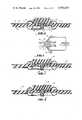
- FIG. 1is a section view of a medical electrode having a conductor fabricated in accordance with the present invention.
- FIG. 2is an elevation view illustrating one mode in which electrode conductors of the general type shown in FIG. 1 can be tested.
- FIG. 3is a section view illustrating a first modification.
- FIG. 4is a section view illustrating a second modification.
- FIG. 5is a section view illustrating a third modification.
- FIG. 6is a perspective view of the conductive electrode element of FIG. 5.
- FIG. 7is a perspective view of a fourth modification.
- FIGS. 8 and 9are section views taken along lines 8--8 and 9--9, respectively, of FIG. 7.
- FIG. 10is a perspective view of a fifth modification and further illustrating a connecting portion of an external conductor for use therewith.
- FIG. 11is a perspective view of the conductive electrode element of FIG. 10.
- FIG. 12is a section view of a sixth modification.
- FIG. 1illustrates an electrode 10 which is of the type shown in FIG. 2 of U.S. Pat. No. 3,969,807 but which has been modified by the inclusion therein of a molded conductor 28, the conductor 28 replacing a two-piece metallic snap fastener which appears in U.S. Pat. No. 3,696,807.
- the electrodecan be seen to comprise confronting cavity washers 12 which sandwich therebetween a sheet 22 of foam plastic material.
- Each of the cavity washers 12is of circular shape and comprises a generally flat central portion 14 and an arched reinforcing bead 16 which encircles the flat portion 14. The bead 16 terminates at its outer edge with a margin 18.
- Each of the cavity washers 12has a central perforation 20 to receive the conductor 28.
- the cavity washersare each fabricated of a relatively thin, molded plastic sheet material which is substantially collapse resistant.
- the aforementioned foam plastic sheet 22comprises a foamed elastic material such as polyvinylchloride and has a layer of pressure sensitive adhesive 24 applied to one surface thereof and protected before use by a release paper 25.
- the sheet 22has a central aperture 26 which is of the same size and which is aligned with the perforations 20 in the cavity washers 12.
- the cavity washers 12are compressed against the central portion of the sheet 22 by means of the one-piece conductor 28.
- the conductor 28can be seen to comprise a molded generally cylindrical body 30 having a circular flange 32 providing an enlarged surface 33 at one end thereof and having a head 34 at the other end thereof.
- the head 34has a neck portion 38 of reduced diameter located between the outer end of the head 34 and an outwardly flared conical portion 36. The construction is such that the head 34 can be pressed through the aligned perforations 20 and through the aperture 26 in the intervening sheet 22 whereby the central portions of the cavity washers 12 and the central portion of the sheet 22 will be received between the flange 32 and the conical portion 36.
- the axial length of the body 30is such that when the head 34 has been pressed axially through both of the perforations 20, the foam sheet 22 is slightly compressed. This causes the foam sheet to expand against and snugly grip the body 30. As appears in FIG. 1 the conductor 28 also presses the cavity washers 12 against the foam sheet 22 with sufficient force that the foam sheet is pinched between the margins 18 of the cavity washers thus assuring that there is little freedom of movement of the foam sheet 22 relative to the cavity washers.
- the adhesive 24 on the sheet 22is located to the same side of the electrode as the surface 33 on the flange 32 of the conductor 28.
- the electrodemay include a pad 40 of cellular material which is soaked with an electrolyte gel or jelly and which contacts the surface 33 of the conductor 28.
- the pad 40is somewhat thicker than the depth of the receiving cup formed by the cavity washer 12 which contacts the flange 32 and, accordingly, when the adhesive coated side of the sheet 22 is pressed against a subject's skin the pad 40 is compressed intimately and firmly against the surface 33.
- the electrode 10was desinged with the objective in view of producing an inexpensive electrode in which a plastic rendered conductive by the dispersion therein of conductive carbon could be molded into the shape of the conductor 28 and acceptable performance for electrocardiograph monitoring obtained.
- a plastic rendered conductive by the dispersion therein of conductive carboncould be molded into the shape of the conductor 28 and acceptable performance for electrocardiograph monitoring obtained.
- the mere dispersion of a conductive carbon in a molded plastic bodydoes not produce an electrode conductor which is considered acceptable for electrocardiographic purposes.
- the problem of inadequate performance of a plastic conductor rendered conductive by the dispersion of carbon therethroughis overcome by the simple expedient of providing at least one particle of metal, which may be vanishingly small, at the interface between the plastic conductor and the electrolyte loaded pad 40.
- FIG. 2illustrates one mode for testing the performance of electrode conductors.
- Two electrodes labeled 10a and 10b, respectively,are constructed in a substantially identical fashion, the conductors 28 of the two electrodes being as nearly identical as possible.
- Each electrodeis contacted with a separate electrolyte loaded sponge which overlies the surface 33 of its conductor 28.
- the two electrodesare assembled face-to-face with the electrolyte sponge 40a received in the electrode 10a intimately contacting the electrolyte sponge 40b of the electrode 10b.
- the end of the conductor of each electrodewhich contacts an electrolyte sponge as the wet end of the conductor and the headed end of the conductor which does not contact the electrolyte loaded sponge as the dry end of the conductor.
- the neck portion of the dry end of the conductor for the electrode 10ais gripped with a pinch clip 42a.
- the dry end of the conductor in the electrode 10bis gripped with a pinch clip 42b.
- An impedance meter 46is connected between the pinch clips 42a and 42b.
- Commercially availabe meters suitable for this mode of testingare the Lab-Line Lectro mho-Meter, Model MC-1, Mark IV marketed by Lab Line Industries, Inc. and the Hewlett-Packard Vector Impedance Meter Model 4800A. All impedance measurements described in this application were made at 1000 H z .
- Commercially available monitoring devices suitable for this purposeare the Cardio-Sentinel Model 505-032-050 Monitor manufactured by Mennen-Greatbatch Electronics, Inc. and, where a permanent record is desired, a Hewlett-Packard Electrocardiograph Model 1500B.
- Finely divided conductive carbonsold under the name Vulcan XC-72 by the Cabot Corporation of Boston, Massachusetts, was thoroughly dispersed, by means of suitable mixing equipment, in an ethylene vinyl acetate copolymer obtained from U.S. Industrial Chemicals Co., Division of National Distillers & Chemical Corporation, New York, New York, to provide a moldable conductive plastic mixture comprising 70-weight percent of the copolymer and 30-weight percent of the conductive carbon.
- a plurality of plastic conductors as shown at 28 in FIG. 1was molded from the mixture.
- Electrodes assembled as in FIG. 1 using plastic conductors from EXAMPLE Iwere contacted with electrolyte sponges and mounted on human subjects.
- the subject mounted electrodesperformed poorly as exemplified by electrocardiographic traces that were irregular in the sense that characteristics common to successive heartbeats were not reproducibly recorded. Such irregularities result from an undesirably high noise level, waveform distortion and sometimes also result from a wandering base line.
- Two of the electrodesexhibited a face-to-face impedance of 2,685 ohms when tested as shown in FIG. 2.
- Plastic conductors from the plurality produced in EXAMPLE Iwere first softened by heating at one end (surface 33 of FIG. 1) of each conductor and contacted with lead power (100 mesh) with a force sufficient to embed lead particles in the surface 33 of each of the conductors.
- the amount of lead embeddedwas approximately 1.2 percent of the initial weight of the conductor.
- the conductors with embedded leadwere assembled into separate electrodes of the type shown in FIG. 1 and each contacted with a gel impregnated electrolyte sponge, the sponges being contacted to the surface of the conductors having lead power embedded therein.
- EXAMPLE IIIwas repeated using, in lieu of lead powder, a silver powder (325 mesh) in the amount of approximately 1.1 percent of the initial part-weight.
- the electrocardiographic traces obtained from subject mounted electrodes from this EXAMPLEwere greatly improved over those traces resulting from electrodes containing the unmodified plastic conductors of EXAMPLE II.
- the average impedance of several pairs of electrodes with silver powder embedded in the plastic conductorswas 326 ohms.
- EXAMPLE IIIwas repeated using, in lieu of lead powder, a zinc powder (325 mesh) in the amount of approximately 1.1 percent of the initial part-weight. Again, the quality of the electrocardiographic traces obtained with subject mounted electrodes from this EXAMPLE was greatly improved over traces obtained with electrodes containing the unmodified plastic conductors of EXAMPLE I. The average impedance of several pairs of electrodes with zinc powder embedded in the plastic conductors was 421 ohms.
- the intimate dispersion of conductive carbon in copolymermight vary in composition from 80-weight percent copolymer/20-weight percent carbon to 50-weight percent copolymer/50-weight percent carbon including all possible compositions between the two extremes.
- the copolymermight be replaced with another plastic such as polyethylene, polypropylene, polyvinylchloride, nylon, Teflon, silicone rubber or various copolymers of the above and terpolymers, such as poly (ethylene propylene ethylidene norbornene), which is commonly abbreviated as EPDM.
- the conductive dispersion abovemight be replaced with any of several conductive plastic molding compositions both thermoplastic and thermosetting available commercially.
- Conductive EPDMcomposed of approximately 45 percent carbon and 55 percent terpolymer and available from Projects Unlimited, Inc. of Dayton, Ohio.
- Conductive polyvinylchlorideavailable from Abbey Plastics Corporation, Hudson, Massachusetts.
- Conductive ethylene vinyl acetate copolymer dispersions of varying carbon contentavailable from U.S. Industrial Chemicals Corporation, New York, New York.
- Vulcan XC-72 conductive carbonmight be replaced by other commercially available conductive carbon blacks.
- the electrical resistivity of the carbon employedmust be of such magnitude to be considered “low”.
- Carbon blacks fitting such a requirementgenerally are also characterized by small particle size and "high-structure” as defined in Encyclopedia of Chemical Technology, Interscience, New York, 2nd Edition, V4 (1964) pgs. 243-247 and 280-281.
- metal powderat one end (surface 33 of FIG. 1) of each plastic conductor during the molding operation.
- silver powder(325 mesh) was brush applied to selected mold cavity surfaces just prior to molding conductive EPDM composed of approximately 45 percent conductive carbon and 55 percent terpolymer available from Projects Unlimited, Inc. of Dayton, Ohio.
- the average face-to-face impedance of final electrode assemblieswas 186 ohms, whereas that of the plastic conductors not containing added metal was 300 ohms.
- the metal embedded in the surface of the plastic conductormay also be in the form of small pieces of thin foil or short lengths of fine wire.
- a plurality of plastic conductorswas molded from a conductive EPDM molding composition consisting of approximately 55 percent terpolymer and 45 percent conductive carbon and available from Projects Unlimited, Inc. of Dayton, Ohio.
- the shape of the molded conductorswas identical to that of EXAMPLE I except that an insert was placed in the mold cavity so that the molded parts each contained a cylindrical indention approximately 1/16 inch in diameter and 1/4 inch deep located within surface 33 of the part as identified in FIG. 1.
- Platinum metal foilwas pressed into the indentations of several plastic conductors from the plurality produced above.
- the weight of platinum foilwas 12.8 percent of the initial weight of the plastic conductors.
- the 1000 H z impedance of face-to-face pairswas 67 ohms.
- platinum wire, gold foil, gold wire or silver foilwere pressed into plastic conductors in the amounts shown in Table II; impedance values at 1000 H z are also indicated in Table II.
- a plurality of plastic conductorswas molded to the shape of the conductor 28 shown in FIG. 1 from a moldable conductive plastic mixture comprising 60-weight percent of an ethylene vinyl acetate copolymer, obtained from U.S. Industrial Chemicals Co., and 40-weight percent of conductive carbon, identified as Vulcan XC-72 and obtained from the Cabot Corporation.
- unpainted plastic conductors from the plurality produced abovewere painted with silver paint such that only 50 percent of the area of the surface 33 was coated.
- silver paintwas applied to several unpainted conductors such that only 25 percent of the surface 33 was coated. Then one small dot of silver paint was applied to the surface 33 of several previously unpainted plastic conductors.
- the weight determinations of applied silver paint and the face-to-face impedances of assembled electrodesare shown in Table III. All of the conductors painted with silver paint, regardless of the area covered, yielded final electrode assemblies that performed better than unpainted plastic conductor assemblies of the same manufacture when subject mounted electrocardiograms were obtained.
- plastic conductors from the same manufacturewere painted with only a small dot of silver paint and then scraped, while viewed through a microscope, to prepare several conductors with only 1/2 a small dot of silver paint and another set of conductors with only 1/10 a small dot of silver paint.
- the estimated weights of paint remaining and face-to-face electrode impedancesare shown in Table III.
- Vulcan XC-72 and 15 parts by weight silver powderwere thoroughly dispersed within 55 parts by weight of an ethylene vinyl acetate copolymer to provide a moldable conductive plastic mixture.
- Conductors molded from a mixture comprising 40 parts by weight XC-72 and 60 parts by weight of the ethylene vinyl acetate copolymer, but lacking any added metalwere used as controls.
- a plurality of plastic conductorswas molded from the mixture including silver powder and assembled into electrodes as in FIG. 1, then contacted with gel impregnated electrolyte sponges.
- the silver powderwas replaced with other metals and alloys to give the face-to-face electrode impedances shown in Table IV.
- the amount of added metal thoroughly dispersed throughout the moldable conductive plastic mixture of EXAMPLE Xcan constitute less than one percent of the total weight of the mixture.
- a mixture of 94-weight percent conductive EPDM molding resin, available from Projects Unlimited, Inc. of Dayton, Ohio, with six-weight percent silver powderwas used to prepare a plurality of plastic conductors as in EXAMPLE I.
- mixtures of 3-weight percent silver/97-weight percent resin and 0.7-weight percent silver/99.3-weight percent resinwere similarly prepared.
- Electrodes assembled with gel impregnated electrolyte sponges and subject mountedgave electrocardiographic traces, in the case of all three of the above formulations, that represented improvements over the performance of plastic conductors containing no added metal.
- the practical upper limit of added metal thoroughly dispersed throughout the moldable conductive plastic mixture of EXAMPLE Xis not known, but can constitute at least 30-weight percent of the total weight of the mixture.
- a series of conductive plastic mixtureswas prepared wherein the weight ratio of an ethylene vinyl acetate molding resin to conductive carbon dispersed therein remained relatively constant, and the amount of dispersed zinc powder was varied from as low as 15-weight percent to as high as 30-weight percent of the total weight of the mixture.
- the electrolyte solutioncomprised a mixture of water, a water swellable mucilage and 7% sodium chloride based on the weight of the electrolyte solution.
- the electrolyte solutioncomprised a mixture of water, a water swellable mucilage and 15% sodium sulfate based on the weight of the electrolyte solution.
- Electrodes made from dissimilar, unalloyed metalssuch as electrode elements having a silver layer over copper, are not encountered in the use of electrodes made in accordance with this invention.
- this benefitmay result from the fact that the conductive plastic is a galvanically inert substance which does not interact electrolytically with the electrolyte.
- the metalthus need not form a complete partition between the electrolyte and the conductive plastic and therefore the amount of metal present at the electrolyte interface can be exceedingly small.
- medical electrodes using the conductors made in accordance with this invention when used with conventional electrolytes and ordinary commercially available monitoring equipmentproduce signal traces having highly stable base lines as well as regular and repetitive wave forms.
- Metalsare frequently distinguished from non-metallic elements or compositions by their conductivity and ability to form positive ions. This line of distinction applies to all of the metals, including alloys, described in the foregoing examples.
- the foregoing examplesaccordingly reveal that the presence of any metal which is securely affixed to or embedded in the surface 33 of the conductor 28, thus contacting some of the conductive carbon distributed throughout the conductor 28, will be effective when contacted to a compatible electrolyte loaded into the sponge 40 to materially enhance the performance of the electrode.
- the selected metal and the selected electrolytewill usually cooperate to produce enhanced performance, and hence be considered compatible, if the metal is galvanically active when contacted to the electrolyte and applied to the skin of a subject.
- the selection of the metal and the electrolytewill depend upon the intended use of the electrode and any selected metal-electrolyte combination must be tested under actual conditions of use for its particular characteristics.
- the relatively low impedance obtained with electrodes in accordance with this inventionis the primary benefit.
- the metal-electrolyte combinationshould function in the sense that a stable base line as well as regular and repetitive wave forms are produced.
- the tests to datesuggest that any metal lodged at the interface of the conductive plastic gives improved results when compared to a conductive plastic without metal.
- the permanency of such improved results, and the magnitude of improvement that can be observedis influenced by the character of the metal and the electrolyte used.
- aluminum and stainless steel particlesare not compatible with sodium chloride electrolytes for use in electrocardiograph monitoring because irregular patterns are formed.
- Sodium sulfate electrolytesare, however, compatible with both aluminum and stainless steel for electrocardiograph purposes.
- Silveris found particularly useful in "prefilled" electrodes made in accordance with this invention in which the electrode is packaged with an electrolyte-loaded sponge material engaging the electrode conductor.
- the preferred electrolytes for use with silverare sodium chloride solutions.
- Such electrodesare reasonably stable over long periods of time if first aged in the package for a period of hours or days while the metal remains in contact with the electrolyte. In addition to convenience offered by prefilling with electrolyte, these electrodes have been found excellent for long term monitoring.
- An electrode made in accordance with this invention wherein the galvanically active conductive material is zinchas proven highly desirable for "dry" electrodes.
- a dry electrodeis packaged without an electrolyte, the electrode being contacted with the electrolyte immediately prior to use.
- Electrodes having a conductor formed from zinc particles in a conductive plastic made in accordance with this inventionhas been found to develop a stable base line for electrocardiograph purposes immediately following contact with either a sodium chloride or a sodium sulfate electrolyte.
- base line stabilityis not reliably maintained beyond a period of several hours or days. Accordingly, electrodes with zinc manufactured in accordance with this invention should not be prefilled.
- metal particlesWhen more than one metal particle is present at the electrolyte interface, it is preferred that all metal particles be of the same metal or alloys of the same chemical composition. If dissimilar, unalloyed, metals are present at the electrolyte interface, base line instability is encountered with the result that regular electrocardiograph traces are not obtained. For the same reasons, the metals or alloys present at the electrolyte interface are preferred to be substantially pure.
- FIG. 1illustrates as a preferred embodiment the dispersion of metal particles 35 throughout the body of the conductor 28.
- This embodimentis presently preferred because of convenience in manufacture since the conductive plastic and metal particles can, after premixing, be molded in one operation.
- Any of the previously described conductors having the various described ranges by weight of dispersed metal particlescan be used. Approximately 15% by weight metal particles is presently preferred when the metal is silver because we have found that sufficient particles will be then present in the mold mix that, invariably, several particles will be present at the interface. A higher percentage of silver particles will not materially enhance the stability of electrode operation and will increase cost. When the metal is zinc, approximately 30% by weight metal particles is presently preferred. The higher zinc content results in a longer period of stability during use. Significantly higher percentages of metal particles may create difficulties in molding.
- the conductor 28also includes finely divided conductive carbon dispersed throughout the body of the conductor. No attempt has been made to particularly illustrate the carbon particles.
- the preferred range of carbon to weight of final productis 25-30% and molding resin by weight is 40-60%.
- FIG. 3illustrates a modification of the preferred embodiment in which the conductor 28 has been press-fitted into a conventional snap fastener part 37.
- the snap fastener part 37contacts any of the embedded metal. It is only important that the part 37 intimately engage the conductor 28.
- the snap fastener part 38provides a convenient means for connecting the electrode of the preferred embodiment to monitoring equipment already commercially available.
- FIG. 4illustrates a further modification in which the conductor 28 is again protected by a conventional snap fastener part 37 and, to show one extreme of the present invention, only a single metal particle 35 has been anchored to the surface 33 of the conductor 28.
- the conductor in all figures of the drawingcomprises a plastic through which has been dispersed finely divided conductive carbon.
- Other formable nonconductorssuch as rubber or ceramics, made conductive by included carbon may also be used with a metal which is galvanically active.
- carbonis thought to be the only available conductive material which can be dispersed through a nonconductor to produce a galvanically inactive conductor. However, if other such materials may be or may become available, they would be useful in the practice of this invention.
- the conductor 28, while described as a part separate from the cavity washer or cup member 12 which receives the flange 32may, in fact, be formed as one piece with the cavity washer 12.
- the cavity washer 12is also conductive and of the same composition as the conductor 28.
- FIGS. 5-12illustrate other forms of medical electrodes utilizing the present invention. These figures of the drawing give a partial indication of the wide variety of medical electrode constructions made possible by this invention.
- FIGS. 5 and 6illustrate an electrode assembly 50 with a one-piece disc-shaped conductor 52 having a projecting hub portion 54 from which, in turn, projects a central stub or head 56.
- the stub 56han an internally splined hole 58 adapted to receive a jack or other electrical connection to external monitoring equipment.
- Hub portion 54is surrounded by a circular foam plastic pad 60 having an adhesive layer 62 engaging a removable cover sheet sheet 64.
- the adhesive layer 62is also in contact with the face of the disc portion of the conductor 52 surrounding the hub 54.
- the electrode assembly 50can be very inexpensively manufactured especially since the conductor 52 with its hub 54 and stub 56 can be molded in one piece from a plastic rendered conductive by included carbon and with a modest percentage of metal particles.
- the electrode 50is intended to be a so-called dry electrode. In use the electrolyte is applied to the exposed face of conductor 52 immediately prior to use.
- the metal preferred in construction of the conductor 52is zinc because, as explained above, zinc is the preferred metal for dry conductors.
- FIGS. 7, 8 and 9disclose an electrode assembly generally designated 66 having a one-piece conductive plate generally designated 68 of a type adapted to be applied to a limb of a patient by a rubber or plastic strap 70.
- plate 68is provided with a first upstanding button or lug 74 and a second upstanding button or lug 76.
- Lugs 74 and 76are adapted to be received within apertures 78 extending the length of the strap 70.
- the second button 76is mounted on top of a female contact member or head 80 which is molded or otherwise formed integrally as part of the plate 68.
- Contact member 80has a splined jack receiving hole 82 which at its exposed end is surrounded by a counterbore 84, the purpose of which will be described below in connection with FIG. 11.
- the plate 68has at least one metal particle at the electrolyte contacting surface 72.
- Electrode assemblies having upstanding lugs or buttonsare not new, one type being shown, for example, in U.S. Pat. No. 2,895,479 granted to R. A. Lloyd on July 21, 1959. However, the advantages of constructing such an electrode assembly with a one-piece molded member rather than from metal are readily apparent.
- FIGS. 10 and 11disclose a novel form of suction electrode generally designated 86 having a one-piece electrode conductor generally designated 88.
- Conductor 88as best illustrated in FIG. 11, comprises a substantially hemispherical cup 90 with a hollow tubular projection 92 opening to the cup 90 and a female electrical connector portion 94.
- the tubular projection 92tightly fits within the neck of a resilient hollow bulb 96 to thus establish communication for air flow between the inside of the bulb 96 and the cup 90.
- an electrolyte gelis smeared on the peripheral edge 98 of the cup 90 or on the patient and the bulb 96 is squeezed. The edge 98 is then engaged with the skin and the squeezed bulb released, whereupon a partial vacuum is created in the cup 90 to maintain it in firm electrical contact with the electrolyte covering the skin.
- the female connector portion 94has a splined hole 100 opening to a counterbore 102 for receiving a jack conductor pin 104 which, as conventional, is surrounded by an insulator having a first, smaller diameter portion 106 and a second, larger diameter portion 108.
- the internal diameter of the splined portion 100is such that the pin 104 is snugly received therein in secure engagement with the conductive plastic from which the splines are formed.
- the diameter of the counterbore 102is only slightly larger than the diameter of the jack insulator portion 106 so that, when the pin 104 is inserted into the hole 100, the insulator portion 106 is received within the counterbore 102 and effectively seals off the hole 100.
- suction electrodesare not new.
- the suction electrode 86 of this inventionis considerably less expensive yet offers the full advantage of conventional suction electrodes.
- a prior suction electrodeis shown in Welsh patent No. 2,580,628 granted by the U.S. Pat. Office on Jan. 1, 1952.
- the suction cup electrode 86 of the instant inventionis most similar to the electrode illustrated in FIG. 3 of the aforementioned Welsh patent.
- the one-piece molded member 88 of the instant inventionperforms all of the functions of the above identified parts and, in addition, provides, by virtue of the insulator part 106 surrounding the jack pin 104, a structure for positively preventing accidental contact between the electrolyte and the jack pin.
- the counterbore 84 of female connector part 80 of the electrode assembly illustrated in FIGS. 7-9is for the same purpose.
- suction electrode 86is illustrated in FIGS. 10 and 11 as larger than actual normal size. Although the electrolyte contacting surface 98 is quite small, suction electrodes 86 in accordance with this invention are quite satisfactory in operation because, as already noted, only a very small metal particle need be present at the edge 98 for proper operation. Suction electrodes have been successfully tested in which the conductor 88 is made with dispersed metal particles as are other electrodes described above.
- FIG. 12illustrates yet another electrode assembly 110 consisting only of a single piece of conductive plastic with dispersed metal in accordance with this invention in which a metal conductor 112 for connection to a remote monitoring device is embedded.
- the area of the piece 110 surrounding the portion thereof receiving the embedded metal conductor 112is covered by a hot melt insulator 114.
- This type of electrodecan, for example, be applied directly to the back of a patient who is bedridden or an adhesive member (not shown) can be used to hold the assembly in contact with the patient.
- the metal conductor 112can extend directly to the monitoring equipment or can have an external connector (not shown) for connection to another conductor. It may be embedded in the conductive plastic part 110 during molding or by other methods.
- the conductor of the present inventionis suitable for use in any application wherein the conductor is to be bridged to a source of periodically varying signals by an electrolyte contacted to at least one metal particle embedded in or otherwise anchored to a surface of the conductor.
Landscapes
- Health & Medical Sciences (AREA)
- Life Sciences & Earth Sciences (AREA)
- Medical Informatics (AREA)
- Molecular Biology (AREA)
- Pathology (AREA)
- Engineering & Computer Science (AREA)
- Biomedical Technology (AREA)
- Heart & Thoracic Surgery (AREA)
- Physics & Mathematics (AREA)
- Biophysics (AREA)
- Surgery (AREA)
- Animal Behavior & Ethology (AREA)
- General Health & Medical Sciences (AREA)
- Public Health (AREA)
- Veterinary Medicine (AREA)
- Cardiology (AREA)
- Measurement And Recording Of Electrical Phenomena And Electrical Characteristics Of The Living Body (AREA)
- Electrotherapy Devices (AREA)
Abstract
Description
TABLE I ______________________________________ Metal Powder (Particle Mesh Size) Avg. Ohms ______________________________________ None 2685 Iron (100) 302 Tin (200) 351 Aluminum (20) 435 Nickel (100) 378 Copper (100) 308 Chromium (100) 474 Manganese (60) 475 Magnesium (100) 401 Gold (200) 248 Nickel-Silver (200) nonferrous alloy of Nickel, Copper and Zinc 428 Stainless Steel 316 (100) 644 Stainless Steel 304 (100) 526 Titanium (20) 392 Bismuth (20) 299 Cadmium (20) 259 ______________________________________
TABLE II ______________________________________ Percent Avg. Added Metal Added Ohms ______________________________________ None -- 300 Platinum Foil 12.8 67 Platinum Wire 18.5 85 Gold Foil 7.2 93 Gold Wire 2.8 84 Silver Foil 27.8 49 ______________________________________
TABLE III ______________________________________ Area Covered Weight with Silver Percent Avg.. Paint Silver Paint Ohms ______________________________________ 0 0 1180 100% 0.60 79 50% 0.33 94 25% 0.20 96 Small Dot 0.09 260 1/2 Small Dot 0.045(estimated) 360 1/10 Small Dot 0.009(estimated) 420 ______________________________________
TABLE IV ______________________________________ ELECTRODE IMPEDANCES AT 1000 HZ. 55 EVA/30 CARBON/15 METAL CONDUCTORS Added Avg. Impedance Metal Ohms ______________________________________ None 5600 Silver (325 Mesh) 143 Iron (100 Mesh) 174 Nickel-Silver (200 Mesh) 800 Stainless Steel 304 (100 Mesh) 1230 Stainless Steel 316 (100 Mesh) 1430 Zinc (325 Mesh) 269 ______________________________________
TABLE V ______________________________________ WEIGHT PERCENT OF MIX COMPONENTS Molding Resin Carbon Silver Powder ______________________________________ 41 50 9 45 40 15 50 35 15 51 40 9 55 30 15 56 35 9 56 29 15 57 28 15 59 26 15 61 30 9 61 24 15 ______________________________________
TABLE VI ______________________________________ Weight Percent Avg. Impedance EVA Resin Carbon Zinc Powder Ohms ______________________________________ 55 30 15 1250 52 28 20 700 50 28 22 530 45.2 24.8 30 195 ______________________________________
Claims (38)
Priority Applications (14)
| Application Number | Priority Date | Filing Date | Title |
|---|---|---|---|
| US05/527,033US3976055A (en) | 1973-12-17 | 1974-11-27 | Electrode and conductor therefor |
| CA215,993ACA1060549A (en) | 1973-12-17 | 1974-12-13 | Bio-potential sensing electrode |
| GB5403274AGB1469425A (en) | 1973-12-17 | 1974-12-13 | Medical electrode |
| SE7415731ASE7415731L (en) | 1973-12-17 | 1974-12-16 | |
| IT54590/74AIT1024491B (en) | 1973-12-17 | 1974-12-16 | ELECTRODE FOR EQUIPMENT FOR MEDICAL USE |
| ES432972AES432972A1 (en) | 1973-12-17 | 1974-12-16 | Electrode and conductor therefor |
| DE2459627ADE2459627C2 (en) | 1973-12-17 | 1974-12-17 | Medical electrode |
| FR7441552AFR2271797B1 (en) | 1973-12-17 | 1974-12-17 | |
| JP14490174AJPS5717528B2 (en) | 1973-12-17 | 1974-12-17 | |
| AU76507/74AAU476069B2 (en) | 1973-12-17 | 1974-12-17 | Medical electrode |
| CH1676474ACH596824A5 (en) | 1973-12-17 | 1974-12-17 | |
| SE8206858ASE8206858D0 (en) | 1973-12-17 | 1982-12-01 | PUT TO MAKE A MEDICAL ELECTROD |
| SE8206857ASE8206857D0 (en) | 1973-12-17 | 1982-12-01 | USE OF A MEDICAL ELECTRODE FOR ECG SURFACES |
| SE8206856ASE8206856D0 (en) | 1973-12-17 | 1982-12-01 | WAY TO PREVENT THE RISE OF METFEL IN ECG SEALS WITH MEDICAL ELECTRODES AND ELECTRODES THEREOF |
Applications Claiming Priority (2)
| Application Number | Priority Date | Filing Date | Title |
|---|---|---|---|
| US42495973A | 1973-12-17 | 1973-12-17 | |
| US05/527,033US3976055A (en) | 1973-12-17 | 1974-11-27 | Electrode and conductor therefor |
Related Parent Applications (1)
| Application Number | Title | Priority Date | Filing Date |
|---|---|---|---|
| US42495973AContinuation-In-Part | 1973-12-17 | 1973-12-17 |
Publications (1)
| Publication Number | Publication Date |
|---|---|
| US3976055Atrue US3976055A (en) | 1976-08-24 |
Family
ID=27026532
Family Applications (1)
| Application Number | Title | Priority Date | Filing Date |
|---|---|---|---|
| US05/527,033Expired - LifetimeUS3976055A (en) | 1973-12-17 | 1974-11-27 | Electrode and conductor therefor |
Country Status (11)
| Country | Link |
|---|---|
| US (1) | US3976055A (en) |
| JP (1) | JPS5717528B2 (en) |
| AU (1) | AU476069B2 (en) |
| CA (1) | CA1060549A (en) |
| CH (1) | CH596824A5 (en) |
| DE (1) | DE2459627C2 (en) |
| ES (1) | ES432972A1 (en) |
| FR (1) | FR2271797B1 (en) |
| GB (1) | GB1469425A (en) |
| IT (1) | IT1024491B (en) |
| SE (1) | SE7415731L (en) |
Cited By (75)
| Publication number | Priority date | Publication date | Assignee | Title |
|---|---|---|---|---|
| US4033334A (en)* | 1975-12-03 | 1977-07-05 | Nasa | Snap-in compressible biomedical electrode |
| US4109648A (en)* | 1975-12-18 | 1978-08-29 | National Research Development Corporation | Electrode assemblies |
| US4117846A (en)* | 1976-05-07 | 1978-10-03 | Consolidated Medical Equipment | Skin conducting electrode and electrode assembly |
| US4126126A (en)* | 1976-07-27 | 1978-11-21 | C. R. Bard, Inc. | Non-metallic pregelled electrode |
| US4235241A (en)* | 1977-09-08 | 1980-11-25 | Tdk Electronics Co., Ltd. | Electrodes for living body |
| US4300575A (en)* | 1979-06-25 | 1981-11-17 | Staodynamics, Inc. | Air-permeable disposable electrode |
| US4321932A (en)* | 1979-06-29 | 1982-03-30 | International Business Machines Corporation | Electrode impedance monitoring method apparatus for electrocardiography |
| US4367755A (en)* | 1979-01-31 | 1983-01-11 | Stimtech, Inc. | Stimulating electrode |
| US4369793A (en)* | 1980-08-18 | 1983-01-25 | Staver Peter J | Medical instrumentation electrode apparatus |
| US4370984A (en)* | 1979-04-30 | 1983-02-01 | Ndm Corporation | X-Ray transparent medical electrode |
| EP0097436A1 (en)* | 1982-06-16 | 1984-01-04 | Minnesota Mining And Manufacturing Company | Bioelectrode |
| FR2531331A1 (en)* | 1982-08-05 | 1984-02-10 | Medicor Muevek | Instrument for measurement of the positions and displacements of joints and of the vertebral column (arthrospinometer) |
| US4458696A (en)* | 1979-08-07 | 1984-07-10 | Minnesota Mining And Manufacturing Company | T.E.N.S. Electrode |
| US4469105A (en)* | 1981-06-18 | 1984-09-04 | Clinton Meyering | Medical electrode apparatus and kit of components therefor |
| US4473492A (en)* | 1983-06-06 | 1984-09-25 | Basf Wyandotte Corporation | Electrode cream |
| US4543958A (en)* | 1979-04-30 | 1985-10-01 | Ndm Corporation | Medical electrode assembly |
| US4555155A (en)* | 1983-11-28 | 1985-11-26 | Minnesota Mining And Manufacturing Company | Bioelectrode connector |
| US4584962A (en)* | 1979-04-30 | 1986-04-29 | Ndm Corporation | Medical electrodes and dispensing conditioner therefor |
| US4590089A (en)* | 1979-04-30 | 1986-05-20 | Ndm Corporation | Medical electrodes and dispensing conditioner therefor |
| US4635642A (en)* | 1985-07-18 | 1987-01-13 | American Hospital Supply Corporation | Medical electrode with reusable conductor |
| FR2586570A1 (en)* | 1985-08-27 | 1987-03-06 | Kureha Chemical Ind Co Ltd | TRANSPARENT X-RAY ELECTRODE FOR A LIVING BODY |
| US4669479A (en)* | 1985-08-21 | 1987-06-02 | Spring Creek Institute, Inc. | Dry electrode system for detection of biopotentials |
| US4674511A (en)* | 1979-04-30 | 1987-06-23 | American Hospital Supply Corporation | Medical electrode |
| US4685467A (en)* | 1985-07-10 | 1987-08-11 | American Hospital Supply Corporation | X-ray transparent medical electrodes and lead wires and assemblies thereof |
| US4699679A (en)* | 1985-07-18 | 1987-10-13 | American Hospital Supply Corporation | Method of manufacturing medical electrode pads |
| US4702732A (en)* | 1984-12-24 | 1987-10-27 | Trustees Of Boston University | Electrodes, electrode assemblies, methods, and systems for tissue stimulation and transdermal delivery of pharmacologically active ligands |
| US4717595A (en)* | 1984-08-31 | 1988-01-05 | Murata Manufacturing Co., Ltd. | Molded carbonaceous material |
| WO1988003821A1 (en)* | 1986-11-21 | 1988-06-02 | Boston University | Electrode assembly for transdermal drug delivery |
| US4786277A (en)* | 1986-11-21 | 1988-11-22 | Trustees Of Boston University | Electrodes, electrode assemblies, methods, and systems for tissue stimulation |
| EP0206441A3 (en)* | 1985-06-18 | 1989-03-22 | Fukuda Denshi Co., Ltd. | Electrocardiographic amorphous alloy electrode |
| US4827939A (en)* | 1985-07-18 | 1989-05-09 | Baxter International Inc. | Medical electrode with reusable conductor and method of manufacture |
| US4838273A (en)* | 1979-04-30 | 1989-06-13 | Baxter International Inc. | Medical electrode |
| US4846185A (en)* | 1987-11-25 | 1989-07-11 | Minnesota Mining And Manufacturing Company | Bioelectrode having a galvanically active interfacing material |
| US4938219A (en)* | 1987-01-16 | 1990-07-03 | Fukuda Denshi Co., Ltd. | Electrocardiographic electrode |
| US4996989A (en)* | 1989-06-15 | 1991-03-05 | Bodylog, Inc. | Electrode |
| EP0449800A1 (en)* | 1990-03-22 | 1991-10-02 | Hermann Bürtlmair | Electrode to be used with a measuring apparatus |
| US5147297A (en)* | 1990-05-07 | 1992-09-15 | Alza Corporation | Iontophoretic delivery device |
| US5195523A (en)* | 1991-04-24 | 1993-03-23 | Ndm Acquisition Corp. | Medical electrode assembly |
| US5352315A (en)* | 1991-07-12 | 1994-10-04 | Ludlow Corporation | Biomedical electrode |
| US5405317A (en)* | 1991-05-03 | 1995-04-11 | Alza Corporation | Iontophoretic delivery device |
| US5407368A (en)* | 1992-12-15 | 1995-04-18 | Minnesota Mining And Manufacturing Company | Electrode connector |
| US5427096A (en)* | 1993-11-19 | 1995-06-27 | Cmc Assemblers, Inc. | Water-degradable electrode |
| US5454739A (en)* | 1992-12-15 | 1995-10-03 | Minnesota Mining And Manufacturing Company | Electrode connector |
| US5489215A (en)* | 1993-08-27 | 1996-02-06 | Micron Medical Products, Inc. | Medical electrode |
| US5493072A (en)* | 1994-06-15 | 1996-02-20 | Amerace Corporation | High voltage cable termination |
| US5505200A (en)* | 1994-01-28 | 1996-04-09 | Minnesota Mining And Manufacturing | Biomedical conductor containing inorganic oxides and biomedical electrodes prepared therefrom |
| WO1996011631A1 (en)* | 1994-10-17 | 1996-04-25 | Biofield Corp. | Dc biopotential sensing electrode and electroconductive medium for use therein |
| USD377219S (en)* | 1994-06-07 | 1997-01-07 | Minnesota Mining And Manufacturing Company | Connector for a biomedical electrode |
| US5660177A (en)* | 1991-11-04 | 1997-08-26 | Biofield Corp. | D.C. biopotential sensing electrode assemblies for apparatus for disease, injury and bodily condition screening or sensing |
| US5702423A (en)* | 1994-10-03 | 1997-12-30 | Mesotes Co. Ltd. | Testing device in a low-voltage, low-frequency beautifying apparatus for detecting lead cord discontinuities |
| US5744421A (en)* | 1996-02-13 | 1998-04-28 | Mega-Carbon Company | Monolithic carbonaceous article |
| US5823957A (en)* | 1994-10-17 | 1998-10-20 | Biofield Corp | D.C. biopotential sensing electrode and electroconductive medium for use therein |
| WO1998053736A1 (en) | 1997-05-30 | 1998-12-03 | Ndm, Inc. | Disposable medical electrode connected to a reusable adapter |
| US5846639A (en)* | 1996-02-13 | 1998-12-08 | Mega-Carbon Company | Monolithic activated carbon |
| US5924983A (en)* | 1996-04-29 | 1999-07-20 | Minnesota Mining And Manufacturing Company | Electrical conductor for biomedical electrodes and biomedical electrodes prepared therefrom |
| US5928142A (en)* | 1996-12-17 | 1999-07-27 | Ndm, Inc. | Biomedical electrode having a disposable electrode and a reusable leadwire adapter that interfaces with a standard leadwire connector |
| US6135953A (en)* | 1996-01-25 | 2000-10-24 | 3M Innovative Properties Company | Multi-functional biomedical electrodes |
| US6356779B1 (en) | 1999-06-04 | 2002-03-12 | 3M Innovative Properties Company | Universally functional biomedical electrode |
| US20050033397A1 (en)* | 2003-08-04 | 2005-02-10 | Integral Technologies, Inc. | Low cost electrical stimulation and shock devices manufactured from conductive loaded resin-based materials |
| US20050261565A1 (en)* | 2004-05-18 | 2005-11-24 | Micron Medical Products | Discretely coated sensor for use in medical electrodes |
| US20060178384A1 (en)* | 2003-07-08 | 2006-08-10 | Hideyuki Sato | Novel chemical compounds |
| US7910129B2 (en) | 2005-12-06 | 2011-03-22 | Tyco Healthcare Group Lp | Carbodiimide crosslinking of functionalized polyethylene glycols |
| WO2011141102A1 (en) | 2010-04-15 | 2011-11-17 | Cerbomed Gmbh | Electrode arrangement for at least partially inserting into an ear canal of a person |
| US8288477B2 (en) | 2005-12-06 | 2012-10-16 | Tyco Healthcare Group Lp | Bioabsorbable compounds and compositions containing them |
| US8353907B2 (en) | 2007-12-21 | 2013-01-15 | Atricure, Inc. | Ablation device with internally cooled electrodes |
| US20130085368A1 (en)* | 2011-09-30 | 2013-04-04 | Tyco Healthcare Group Lp | Radiolucent ECG Electrode And Method Of Making Same |
| US8441771B2 (en) | 2009-07-23 | 2013-05-14 | Taser International, Inc. | Electronic weaponry with current spreading electrode |
| US8449714B2 (en) | 2005-12-08 | 2013-05-28 | Covidien Lp | Biocompatible surgical compositions |
| US8587918B2 (en) | 2010-07-23 | 2013-11-19 | Taser International, Inc. | Systems and methods for electrodes for insulative electronic weaponry |
| US8998892B2 (en) | 2007-12-21 | 2015-04-07 | Atricure, Inc. | Ablation device with cooled electrodes and methods of use |
| US20150141790A1 (en)* | 2013-11-18 | 2015-05-21 | Siemens Aktiengesellschaft | Sensor instrument |
| US20180028089A1 (en)* | 2015-02-23 | 2018-02-01 | Nihon Kohden Corporation | Electroencephalogram electrode |
| US10639827B2 (en) | 2015-12-22 | 2020-05-05 | 3M Innovative Properties Company | Eyelet for biomedical electrode and process for production thereof |
| US10800079B2 (en) | 2015-12-22 | 2020-10-13 | 3M Innovative Properties Company | One-piece sensor for a bioelectrode and processes for production |
| US11304640B2 (en) | 2015-12-22 | 2022-04-19 | 3M Innovative Properties Company | Sensor for electrode and processes for production |
Families Citing this family (12)
| Publication number | Priority date | Publication date | Assignee | Title |
|---|---|---|---|---|
| JPS5288290U (en)* | 1975-12-22 | 1977-07-01 | ||
| DE2735050C3 (en)* | 1977-08-03 | 1981-06-25 | Siemens AG, 1000 Berlin und 8000 München | electrode |
| EP0000759B1 (en)* | 1977-08-03 | 1981-09-02 | Siemens Aktiengesellschaft | Electrode |
| DE2742058A1 (en)* | 1977-09-19 | 1979-03-29 | Guenter Prof Dipl Ing Dr R Rau | Fixture for data pick=up and measuring electrode - has flexible one-piece suction cup of plastics esp. for use on skin surfaces |
| JPS60166307U (en)* | 1984-04-12 | 1985-11-05 | フクダ電子株式会社 | Clip-type electrode for electrocardiograph |
| JPS60166306U (en)* | 1984-04-12 | 1985-11-05 | フクダ電子株式会社 | Clip-type electrode for electrocardiograph |
| JPH024322A (en)* | 1988-06-13 | 1990-01-09 | Fukuda Denshi Co Ltd | Bioinductive electrodes for limbs |
| JPH024324A (en)* | 1988-06-13 | 1990-01-09 | Fukuda Denshi Co Ltd | Organism induction electrode for chest |
| DE3906074A1 (en)* | 1989-02-27 | 1990-08-30 | Schmid Walter | Method of producing a body electrode |
| DE3906071A1 (en)* | 1989-02-27 | 1990-08-30 | Schmid Walter | Body electrode |
| EA022142B1 (en)* | 2012-10-01 | 2015-11-30 | Федеральное Государственное Бюджетное Образовательное Учреждение Высшего Профессионального Образования "Национальный Исследовательский Томский Политехнический Университет" (Фгбоу Впо Ни Тпу) | Electrode device |
| JP2023032198A (en)* | 2021-08-26 | 2023-03-09 | テルモ株式会社 | Dry electrode and wearable device |
Citations (20)
| Publication number | Priority date | Publication date | Assignee | Title |
|---|---|---|---|---|
| US1053881A (en)* | 1911-09-21 | 1913-02-18 | Campbell Scott | Composition of matter. |
| US2580628A (en)* | 1950-07-12 | 1952-01-01 | Bowen & Company Inc | Suction electrode |
| US2782786A (en)* | 1955-10-10 | 1957-02-26 | Louis R Krasno | Electrocardiograph electrode with absorbent contact surface |
| US3003975A (en)* | 1958-11-26 | 1961-10-10 | Myron A Coler | Conductive plastic composition and method of making the same |
| US3029808A (en)* | 1957-07-30 | 1962-04-17 | Arco Mfg Corp | Direct current medical amplifier |
| US3083169A (en)* | 1959-10-12 | 1963-03-26 | Ueda Yoshitaka | Manufacturing method of electrical conductive plastics |
| US3385677A (en)* | 1965-06-30 | 1968-05-28 | Siemens Ag | Sintered composition material |
| DE1466919A1 (en)* | 1965-05-14 | 1969-07-17 | Peter Schmidt | EKG electrode |
| US3474775A (en)* | 1967-02-27 | 1969-10-28 | William R Johnson | Electrode assembly for skin contact |
| US3490442A (en)* | 1966-02-09 | 1970-01-20 | Hellige & Co Gmbh F | Electrode with contact-forming suction cup means |
| US3566860A (en)* | 1968-12-20 | 1971-03-02 | United Aircraft Corp | Carbon-impregnated body electrode |
| US3599629A (en)* | 1968-08-28 | 1971-08-17 | Lexington Instr | Oxidized surface biopotential skin electrode |
| US3602216A (en)* | 1969-09-16 | 1971-08-31 | United Aircraft Corp | Paste dispensing body electrode |
| US3606881A (en)* | 1970-02-20 | 1971-09-21 | Riley D Woodson | Conductive rubber electrode |
| US3701346A (en)* | 1971-01-04 | 1972-10-31 | Bionetics Inc | Medical electrode |
| US3721246A (en)* | 1970-12-10 | 1973-03-20 | Thomas & Betts Corp | Applicator electrodes with a very thin non-metallic, current distributing layer |
| US3733385A (en)* | 1967-12-04 | 1973-05-15 | Ici Ltd | Method of making conducting plastic articles |
| US3760495A (en)* | 1970-01-27 | 1973-09-25 | Texas Instruments Inc | Process for making conductive polymers |
| US3792700A (en)* | 1972-03-01 | 1974-02-19 | Survival Technology | Apparatus and method of monitoring the electrical activity of the heart of a human with armpit located electrodes |
| US3828766A (en)* | 1972-08-14 | 1974-08-13 | Jet Medical Prod Inc | Disposable medical electrode |
Family Cites Families (1)
| Publication number | Priority date | Publication date | Assignee | Title |
|---|---|---|---|---|
| AT166601B (en)* | 1946-07-24 | 1950-08-25 | Gen Electric | Process for the union of bodies, of which at least one consists of ceramic material |
- 1974
- 1974-11-27USUS05/527,033patent/US3976055A/ennot_activeExpired - Lifetime
- 1974-12-13GBGB5403274Apatent/GB1469425A/ennot_activeExpired
- 1974-12-13CACA215,993Apatent/CA1060549A/ennot_activeExpired
- 1974-12-16SESE7415731Apatent/SE7415731L/unknown
- 1974-12-16ITIT54590/74Apatent/IT1024491B/enactive
- 1974-12-16ESES432972Apatent/ES432972A1/ennot_activeExpired
- 1974-12-17CHCH1676474Apatent/CH596824A5/xxnot_activeIP Right Cessation
- 1974-12-17DEDE2459627Apatent/DE2459627C2/ennot_activeExpired
- 1974-12-17FRFR7441552Apatent/FR2271797B1/frnot_activeExpired
- 1974-12-17AUAU76507/74Apatent/AU476069B2/ennot_activeExpired
- 1974-12-17JPJP14490174Apatent/JPS5717528B2/janot_activeExpired
Patent Citations (20)
| Publication number | Priority date | Publication date | Assignee | Title |
|---|---|---|---|---|
| US1053881A (en)* | 1911-09-21 | 1913-02-18 | Campbell Scott | Composition of matter. |
| US2580628A (en)* | 1950-07-12 | 1952-01-01 | Bowen & Company Inc | Suction electrode |
| US2782786A (en)* | 1955-10-10 | 1957-02-26 | Louis R Krasno | Electrocardiograph electrode with absorbent contact surface |
| US3029808A (en)* | 1957-07-30 | 1962-04-17 | Arco Mfg Corp | Direct current medical amplifier |
| US3003975A (en)* | 1958-11-26 | 1961-10-10 | Myron A Coler | Conductive plastic composition and method of making the same |
| US3083169A (en)* | 1959-10-12 | 1963-03-26 | Ueda Yoshitaka | Manufacturing method of electrical conductive plastics |
| DE1466919A1 (en)* | 1965-05-14 | 1969-07-17 | Peter Schmidt | EKG electrode |
| US3385677A (en)* | 1965-06-30 | 1968-05-28 | Siemens Ag | Sintered composition material |
| US3490442A (en)* | 1966-02-09 | 1970-01-20 | Hellige & Co Gmbh F | Electrode with contact-forming suction cup means |
| US3474775A (en)* | 1967-02-27 | 1969-10-28 | William R Johnson | Electrode assembly for skin contact |
| US3733385A (en)* | 1967-12-04 | 1973-05-15 | Ici Ltd | Method of making conducting plastic articles |
| US3599629A (en)* | 1968-08-28 | 1971-08-17 | Lexington Instr | Oxidized surface biopotential skin electrode |
| US3566860A (en)* | 1968-12-20 | 1971-03-02 | United Aircraft Corp | Carbon-impregnated body electrode |
| US3602216A (en)* | 1969-09-16 | 1971-08-31 | United Aircraft Corp | Paste dispensing body electrode |
| US3760495A (en)* | 1970-01-27 | 1973-09-25 | Texas Instruments Inc | Process for making conductive polymers |
| US3606881A (en)* | 1970-02-20 | 1971-09-21 | Riley D Woodson | Conductive rubber electrode |
| US3721246A (en)* | 1970-12-10 | 1973-03-20 | Thomas & Betts Corp | Applicator electrodes with a very thin non-metallic, current distributing layer |
| US3701346A (en)* | 1971-01-04 | 1972-10-31 | Bionetics Inc | Medical electrode |
| US3792700A (en)* | 1972-03-01 | 1974-02-19 | Survival Technology | Apparatus and method of monitoring the electrical activity of the heart of a human with armpit located electrodes |
| US3828766A (en)* | 1972-08-14 | 1974-08-13 | Jet Medical Prod Inc | Disposable medical electrode |
Cited By (95)
| Publication number | Priority date | Publication date | Assignee | Title |
|---|---|---|---|---|
| US4033334A (en)* | 1975-12-03 | 1977-07-05 | Nasa | Snap-in compressible biomedical electrode |
| US4109648A (en)* | 1975-12-18 | 1978-08-29 | National Research Development Corporation | Electrode assemblies |
| US4117846A (en)* | 1976-05-07 | 1978-10-03 | Consolidated Medical Equipment | Skin conducting electrode and electrode assembly |
| US4126126A (en)* | 1976-07-27 | 1978-11-21 | C. R. Bard, Inc. | Non-metallic pregelled electrode |
| US4235241A (en)* | 1977-09-08 | 1980-11-25 | Tdk Electronics Co., Ltd. | Electrodes for living body |
| US4367755A (en)* | 1979-01-31 | 1983-01-11 | Stimtech, Inc. | Stimulating electrode |
| US4674511A (en)* | 1979-04-30 | 1987-06-23 | American Hospital Supply Corporation | Medical electrode |
| US4543958A (en)* | 1979-04-30 | 1985-10-01 | Ndm Corporation | Medical electrode assembly |
| US4838273A (en)* | 1979-04-30 | 1989-06-13 | Baxter International Inc. | Medical electrode |
| US4370984A (en)* | 1979-04-30 | 1983-02-01 | Ndm Corporation | X-Ray transparent medical electrode |
| US4590089A (en)* | 1979-04-30 | 1986-05-20 | Ndm Corporation | Medical electrodes and dispensing conditioner therefor |
| US4584962A (en)* | 1979-04-30 | 1986-04-29 | Ndm Corporation | Medical electrodes and dispensing conditioner therefor |
| US4300575A (en)* | 1979-06-25 | 1981-11-17 | Staodynamics, Inc. | Air-permeable disposable electrode |
| US4321932A (en)* | 1979-06-29 | 1982-03-30 | International Business Machines Corporation | Electrode impedance monitoring method apparatus for electrocardiography |
| US4458696A (en)* | 1979-08-07 | 1984-07-10 | Minnesota Mining And Manufacturing Company | T.E.N.S. Electrode |
| US4369793A (en)* | 1980-08-18 | 1983-01-25 | Staver Peter J | Medical instrumentation electrode apparatus |
| US4469105A (en)* | 1981-06-18 | 1984-09-04 | Clinton Meyering | Medical electrode apparatus and kit of components therefor |
| EP0097436A1 (en)* | 1982-06-16 | 1984-01-04 | Minnesota Mining And Manufacturing Company | Bioelectrode |
| FR2531331A1 (en)* | 1982-08-05 | 1984-02-10 | Medicor Muevek | Instrument for measurement of the positions and displacements of joints and of the vertebral column (arthrospinometer) |
| US4473492A (en)* | 1983-06-06 | 1984-09-25 | Basf Wyandotte Corporation | Electrode cream |
| US4555155A (en)* | 1983-11-28 | 1985-11-26 | Minnesota Mining And Manufacturing Company | Bioelectrode connector |
| US4717595A (en)* | 1984-08-31 | 1988-01-05 | Murata Manufacturing Co., Ltd. | Molded carbonaceous material |
| US4702732A (en)* | 1984-12-24 | 1987-10-27 | Trustees Of Boston University | Electrodes, electrode assemblies, methods, and systems for tissue stimulation and transdermal delivery of pharmacologically active ligands |
| EP0206441A3 (en)* | 1985-06-18 | 1989-03-22 | Fukuda Denshi Co., Ltd. | Electrocardiographic amorphous alloy electrode |
| US4685467A (en)* | 1985-07-10 | 1987-08-11 | American Hospital Supply Corporation | X-ray transparent medical electrodes and lead wires and assemblies thereof |
| EP0210020A3 (en)* | 1985-07-10 | 1989-03-08 | Ndm Acquisition Corp. | X-ray transparent medical electrodes and lead wires and assemblies thereof |
| US4699679A (en)* | 1985-07-18 | 1987-10-13 | American Hospital Supply Corporation | Method of manufacturing medical electrode pads |
| US4635642A (en)* | 1985-07-18 | 1987-01-13 | American Hospital Supply Corporation | Medical electrode with reusable conductor |
| US4827939A (en)* | 1985-07-18 | 1989-05-09 | Baxter International Inc. | Medical electrode with reusable conductor and method of manufacture |
| US4669479A (en)* | 1985-08-21 | 1987-06-02 | Spring Creek Institute, Inc. | Dry electrode system for detection of biopotentials |
| FR2586570A1 (en)* | 1985-08-27 | 1987-03-06 | Kureha Chemical Ind Co Ltd | TRANSPARENT X-RAY ELECTRODE FOR A LIVING BODY |
| WO1988003821A1 (en)* | 1986-11-21 | 1988-06-02 | Boston University | Electrode assembly for transdermal drug delivery |
| GB2204497A (en)* | 1986-11-21 | 1988-11-16 | Univ Boston | Electrode assembly for transdermal drug delivery |
| US4786277A (en)* | 1986-11-21 | 1988-11-22 | Trustees Of Boston University | Electrodes, electrode assemblies, methods, and systems for tissue stimulation |
| GB2204497B (en)* | 1986-11-21 | 1991-02-27 | Univ Boston | Electrode assembly for transdermal drug delivery |
| US4938219A (en)* | 1987-01-16 | 1990-07-03 | Fukuda Denshi Co., Ltd. | Electrocardiographic electrode |
| US4846185A (en)* | 1987-11-25 | 1989-07-11 | Minnesota Mining And Manufacturing Company | Bioelectrode having a galvanically active interfacing material |
| US4996989A (en)* | 1989-06-15 | 1991-03-05 | Bodylog, Inc. | Electrode |
| EP0449800A1 (en)* | 1990-03-22 | 1991-10-02 | Hermann Bürtlmair | Electrode to be used with a measuring apparatus |
| US5147297A (en)* | 1990-05-07 | 1992-09-15 | Alza Corporation | Iontophoretic delivery device |
| US5195523A (en)* | 1991-04-24 | 1993-03-23 | Ndm Acquisition Corp. | Medical electrode assembly |
| US5405273A (en)* | 1991-04-24 | 1995-04-11 | Ndm Acquisition Corp. | Medical electrode assembly |
| US5405317A (en)* | 1991-05-03 | 1995-04-11 | Alza Corporation | Iontophoretic delivery device |
| US5352315A (en)* | 1991-07-12 | 1994-10-04 | Ludlow Corporation | Biomedical electrode |
| US5660177A (en)* | 1991-11-04 | 1997-08-26 | Biofield Corp. | D.C. biopotential sensing electrode assemblies for apparatus for disease, injury and bodily condition screening or sensing |
| US5407368A (en)* | 1992-12-15 | 1995-04-18 | Minnesota Mining And Manufacturing Company | Electrode connector |
| US5454739A (en)* | 1992-12-15 | 1995-10-03 | Minnesota Mining And Manufacturing Company | Electrode connector |
| US5538444A (en)* | 1992-12-15 | 1996-07-23 | Minnesota Mining And Manufacturing Company | Electrode connector |
| US5489215A (en)* | 1993-08-27 | 1996-02-06 | Micron Medical Products, Inc. | Medical electrode |
| US5499628A (en)* | 1993-08-27 | 1996-03-19 | Micron Medical Products, Inc. | Medical electrode |
| US5427096A (en)* | 1993-11-19 | 1995-06-27 | Cmc Assemblers, Inc. | Water-degradable electrode |
| US5505200A (en)* | 1994-01-28 | 1996-04-09 | Minnesota Mining And Manufacturing | Biomedical conductor containing inorganic oxides and biomedical electrodes prepared therefrom |
| USD377219S (en)* | 1994-06-07 | 1997-01-07 | Minnesota Mining And Manufacturing Company | Connector for a biomedical electrode |
| US5493072A (en)* | 1994-06-15 | 1996-02-20 | Amerace Corporation | High voltage cable termination |
| AU674267B2 (en)* | 1994-06-15 | 1996-12-12 | Thomas & Betts International, Inc. | An elastomeric capacitively graded high voltage cable termination |
| US5702423A (en)* | 1994-10-03 | 1997-12-30 | Mesotes Co. Ltd. | Testing device in a low-voltage, low-frequency beautifying apparatus for detecting lead cord discontinuities |
| WO1996011631A1 (en)* | 1994-10-17 | 1996-04-25 | Biofield Corp. | Dc biopotential sensing electrode and electroconductive medium for use therein |
| US5823957A (en)* | 1994-10-17 | 1998-10-20 | Biofield Corp | D.C. biopotential sensing electrode and electroconductive medium for use therein |
| US6135953A (en)* | 1996-01-25 | 2000-10-24 | 3M Innovative Properties Company | Multi-functional biomedical electrodes |
| US5744421A (en)* | 1996-02-13 | 1998-04-28 | Mega-Carbon Company | Monolithic carbonaceous article |
| US6207264B1 (en) | 1996-02-13 | 2001-03-27 | Mega-Carbon Company | Monolithic activated carbon |
| US5846639A (en)* | 1996-02-13 | 1998-12-08 | Mega-Carbon Company | Monolithic activated carbon |
| US5924983A (en)* | 1996-04-29 | 1999-07-20 | Minnesota Mining And Manufacturing Company | Electrical conductor for biomedical electrodes and biomedical electrodes prepared therefrom |
| US6023631A (en)* | 1996-12-17 | 2000-02-08 | Ndm, Inc. | Biomedical electrode having a disposable electrode and a reusable leadwire adapter that interfaces with a standard leadwire connector |
| US5928142A (en)* | 1996-12-17 | 1999-07-27 | Ndm, Inc. | Biomedical electrode having a disposable electrode and a reusable leadwire adapter that interfaces with a standard leadwire connector |
| US6064901A (en)* | 1996-12-17 | 2000-05-16 | Ndm, Inc. | Biomedical electrode having a disposable electrode and a reusable leadwire adapter that interfaces with a standard leadwire connector |
| US6076002A (en)* | 1996-12-17 | 2000-06-13 | Ndm, Inc. | Method of manufacturing a disposable electrode |
| US5921925A (en)* | 1997-05-30 | 1999-07-13 | Ndm, Inc. | Biomedical electrode having a disposable electrode and a reusable leadwire adapter that interfaces with a standard leadwire connector |
| WO1998053736A1 (en) | 1997-05-30 | 1998-12-03 | Ndm, Inc. | Disposable medical electrode connected to a reusable adapter |
| US6276054B1 (en) | 1997-05-30 | 2001-08-21 | Ndm, Inc. | Method of manufacturing a disposable electrode |
| US6701172B2 (en) | 1999-06-04 | 2004-03-02 | 3M Innovative Properties Company | Universally functional biomedical electrode |
| US6356779B1 (en) | 1999-06-04 | 2002-03-12 | 3M Innovative Properties Company | Universally functional biomedical electrode |
| US20060178384A1 (en)* | 2003-07-08 | 2006-08-10 | Hideyuki Sato | Novel chemical compounds |
| US7501512B2 (en) | 2003-07-08 | 2009-03-10 | Smithkline Beecham Corporation | Chemical compounds |
| US20050033397A1 (en)* | 2003-08-04 | 2005-02-10 | Integral Technologies, Inc. | Low cost electrical stimulation and shock devices manufactured from conductive loaded resin-based materials |
| US20050261565A1 (en)* | 2004-05-18 | 2005-11-24 | Micron Medical Products | Discretely coated sensor for use in medical electrodes |
| WO2005115229A3 (en)* | 2004-05-18 | 2006-10-19 | Micron Medical Products | Discretely coated sensor for use in medical electrodes |
| US8288477B2 (en) | 2005-12-06 | 2012-10-16 | Tyco Healthcare Group Lp | Bioabsorbable compounds and compositions containing them |
| US7910129B2 (en) | 2005-12-06 | 2011-03-22 | Tyco Healthcare Group Lp | Carbodiimide crosslinking of functionalized polyethylene glycols |
| US8449714B2 (en) | 2005-12-08 | 2013-05-28 | Covidien Lp | Biocompatible surgical compositions |
| US8915878B2 (en) | 2007-12-21 | 2014-12-23 | Atricure, Inc. | Ablation device with internally cooled electrodes |
| US8998892B2 (en) | 2007-12-21 | 2015-04-07 | Atricure, Inc. | Ablation device with cooled electrodes and methods of use |
| US8353907B2 (en) | 2007-12-21 | 2013-01-15 | Atricure, Inc. | Ablation device with internally cooled electrodes |
| US8441771B2 (en) | 2009-07-23 | 2013-05-14 | Taser International, Inc. | Electronic weaponry with current spreading electrode |
| WO2011141102A1 (en) | 2010-04-15 | 2011-11-17 | Cerbomed Gmbh | Electrode arrangement for at least partially inserting into an ear canal of a person |
| US8587918B2 (en) | 2010-07-23 | 2013-11-19 | Taser International, Inc. | Systems and methods for electrodes for insulative electronic weaponry |
| US20130085368A1 (en)* | 2011-09-30 | 2013-04-04 | Tyco Healthcare Group Lp | Radiolucent ECG Electrode And Method Of Making Same |
| US20150141790A1 (en)* | 2013-11-18 | 2015-05-21 | Siemens Aktiengesellschaft | Sensor instrument |
| US9706936B2 (en)* | 2013-11-18 | 2017-07-18 | Siemens Aktiengesellschaft | Sensor instrument |
| US20180028089A1 (en)* | 2015-02-23 | 2018-02-01 | Nihon Kohden Corporation | Electroencephalogram electrode |
| US11647936B2 (en)* | 2015-02-23 | 2023-05-16 | Nihon Kohden Corporation | Electroencephalogram electrode |
| US10639827B2 (en) | 2015-12-22 | 2020-05-05 | 3M Innovative Properties Company | Eyelet for biomedical electrode and process for production thereof |
| US10800079B2 (en) | 2015-12-22 | 2020-10-13 | 3M Innovative Properties Company | One-piece sensor for a bioelectrode and processes for production |
| US10857704B2 (en) | 2015-12-22 | 2020-12-08 | 3M Innovative Properties Company | Eyelet for biomedical electrode and process for production thereof |
| US11304640B2 (en) | 2015-12-22 | 2022-04-19 | 3M Innovative Properties Company | Sensor for electrode and processes for production |
Also Published As
| Publication number | Publication date |
|---|---|
| FR2271797A1 (en) | 1975-12-19 |
| AU476069B2 (en) | 1976-09-09 |
| DE2459627A1 (en) | 1975-06-19 |
| GB1469425A (en) | 1977-04-06 |
| FR2271797B1 (en) | 1978-10-13 |
| ES432972A1 (en) | 1976-09-01 |
| JPS5717528B2 (en) | 1982-04-12 |
| SE7415731L (en) | 1975-06-18 |
| CH596824A5 (en) | 1978-03-31 |
| IT1024491B (en) | 1978-06-20 |
| DE2459627C2 (en) | 1982-04-22 |
| AU7650774A (en) | 1976-06-17 |
| JPS50106481A (en) | 1975-08-21 |
| CA1060549A (en) | 1979-08-14 |
Similar Documents
| Publication | Publication Date | Title |
|---|---|---|
| US3976055A (en) | Electrode and conductor therefor | |
| US4166453A (en) | Body electrodes | |
| US4027664A (en) | Diagnostic electrode assembly with a skin preparation surface | |
| US5465715A (en) | Positive locking biomedical electrode and connector system | |
| US5337748A (en) | Biosignal electrode | |
| US5211174A (en) | Low impedance, low durometer, dry conforming contact element | |
| CA1280174C (en) | X-ray transparent medical electrodes and lead wires and assemblies thereof | |
| US5372125A (en) | Positive locking biomedical electrode and connector system | |
| US5405273A (en) | Medical electrode assembly | |
| US4126126A (en) | Non-metallic pregelled electrode | |
| US4077398A (en) | Diagnostic electrode assembly | |
| US4125110A (en) | Monitoring and stimulation electrode | |
| US3599629A (en) | Oxidized surface biopotential skin electrode | |
| US20050261565A1 (en) | Discretely coated sensor for use in medical electrodes | |
| USRE31454E (en) | Monitoring and stimulation electrode | |
| US3487827A (en) | Electrode for electromedical equipment | |
| US3964469A (en) | Disposable electrode | |
| JPH0595922A (en) | Electrode for organism and manufacture thereof | |
| WO1979000042A1 (en) | Biomedical electrode assembly | |
| EP0884021B1 (en) | Biomedical electrode provided with a press stud | |
| JPH077923Y2 (en) | Multi-electrode biomedical electrode | |
| US3820531A (en) | Medical electrode | |
| CA1144606A (en) | Skin contact pellet for bio-electric signal measurement | |
| JPH0731597A (en) | Adhesive sheet electrode | |
| KR900006903Y1 (en) | Biomulti electrode |
Legal Events
| Date | Code | Title | Description |
|---|---|---|---|
| AS | Assignment | Owner name:AMERICAN HOSPITAL SUPPLY CORPORATION, EVANSTON, IL Free format text:ASSIGNMENT OF ASSIGNORS INTEREST.;ASSIGNOR:NDM CORPORATION, A CORP. OF OHIO;REEL/FRAME:004495/0141 Effective date:19851125 | |
| AS | Assignment | Owner name:BAXTER TRAVENOL LABORATORIES, INC. A CORP. OF DE Free format text:MERGER;ASSIGNOR:AMERICAN HOSPITAL SUPPLY CORPORATION INTO;REEL/FRAME:004760/0345 Effective date:19870126 | |
| STCF | Information on status: patent grant | Free format text:PATENTED FILE - (OLD CASE ADDED FOR FILE TRACKING PURPOSES) | |
| AS | Assignment | Owner name:NDM ACQUISITION CORP., MINNESOTA Free format text:ASSIGNMENT OF ASSIGNORS INTEREST.;ASSIGNORS:BAXTER INTERNATIONAL INC.;BAXTER HEALTHCARE CORPORATION OF PUERTO RICO;REEL/FRAME:005254/0845 Effective date:19891031 | |
| AS | Assignment | Owner name:BANK ONE, DAYTON, NATIONAL ASSOCIATION Free format text:SECURITY INTEREST;ASSIGNOR:NDM ACQUISITION CORP., A MN CORP.;REEL/FRAME:006104/0385 Effective date:19920430 | |
| AS | Assignment | Owner name:NDM, INC., NEW YORK Free format text:ASSIGNMENT OF ASSIGNORS INTEREST;ASSIGNOR:NEW DIMENSIONS IN MEDICINE, INC.;REEL/FRAME:007833/0379 Effective date:19960219 Owner name:NEW DIMENSIONS IN MEDICINE, INC., OHIO Free format text:RELEASE BY SECURED PARTY;ASSIGNOR:BANK ONE, DAYTON, NATIONAL ASSOCIATION;REEL/FRAME:007833/0476 Effective date:19960223 | |
| AS | Assignment | Owner name:CONMED CORPORATION, NEW YORK Free format text:ASSIGNMENT OF ASSIGNORS INTEREST;ASSIGNOR:NDM, INC.;REEL/FRAME:013258/0974 Effective date:19991105 |