US3973359A - Web abrading assembly - Google Patents
Web abrading assemblyDownload PDFInfo
- Publication number
- US3973359A US3973359AUS05/589,413US58941375AUS3973359AUS 3973359 AUS3973359 AUS 3973359AUS 58941375 AUS58941375 AUS 58941375AUS 3973359 AUS3973359 AUS 3973359A
- Authority
- US
- United States
- Prior art keywords
- abrading
- fabric
- continuous web
- assembly
- cylindrical
- Prior art date
- Legal status (The legal status is an assumption and is not a legal conclusion. Google has not performed a legal analysis and makes no representation as to the accuracy of the status listed.)
- Expired - Lifetime
Links
Images
Classifications
- B—PERFORMING OPERATIONS; TRANSPORTING
- B24—GRINDING; POLISHING
- B24B—MACHINES, DEVICES, OR PROCESSES FOR GRINDING OR POLISHING; DRESSING OR CONDITIONING OF ABRADING SURFACES; FEEDING OF GRINDING, POLISHING, OR LAPPING AGENTS
- B24B7/00—Machines or devices designed for grinding plane surfaces on work, including polishing plane glass surfaces; Accessories therefor
- B24B7/10—Single-purpose machines or devices
- B24B7/12—Single-purpose machines or devices for grinding travelling elongated stock, e.g. strip-shaped work
- B24B7/13—Single-purpose machines or devices for grinding travelling elongated stock, e.g. strip-shaped work grinding while stock moves from coil to coil
- D—TEXTILES; PAPER
- D06—TREATMENT OF TEXTILES OR THE LIKE; LAUNDERING; FLEXIBLE MATERIALS NOT OTHERWISE PROVIDED FOR
- D06C—FINISHING, DRESSING, TENTERING OR STRETCHING TEXTILE FABRICS
- D06C11/00—Teasing, napping or otherwise roughening or raising pile of textile fabrics
Definitions
- the yarnsare raised above the base of the fabric to form a pile surface or the fibers of the yarns may be ruptured depending upon the nature of the yarns whether made of staple or continuous filaments as in the case of multifilament synthetic yarns.
- an abrading surfacewhether sandpaper or wire clothing or a knurled surface, such surfaces become worn after extended use depending upon the abrasion characteristics of the fabrics being finished.
- Another objective of this inventionis to provide an apparatus for abrading traveling fabric to impart desired finishing characteristics to at least one of the surfaces thereof in which the abrading apparatus has a plurality of incrementally changeable surfaces to be exposed when one or more surfaces have become worn.
- Yet another objective of this inventionis to provide a fabric abrading machine having a plurality of fabric abrading rolls which are spaced from each other along the path of fabric travel in which each roll is provided with a plurality of independent fabric engaging abrading surfaces which surfaces may be rotated when worn.
- Still another objective of this inventionis the provision of an apparatus in the form of a rotating assembly having a series of circumferentially and radially supported and spaced abrading surfaces which may be modified when worn in the path of fabric travel with relative ease and a minimum of labor.
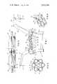
- FIG. 1is a side elevational view of a fabric abrading machine showing the path of travel of the fabric and a plurality of fabric abrading devices in position for abrading the traveling fabric in its path of travel from inlet to discharge;
- FIG. 2is an enlarged and elevational view of one of the fabric abrading rolls illustrating a plurality of individual cylindrical tubular members supporting an abrading surface;
- FIG. 3is a top plan view with a medial section removed from one of the roll assemblies.
- FIG. 4is a partial perspective view of one portion of the roll assembly in exploded perspective illustrating the various elements in one portion of the assembly.
- FIG. 1 of the drawingAn apparatus 10 for abrading a continuously moving textile web of fabric 11 which enters the apparatus over the inlet roller and the guide 12 supported on the upstanding arm 13 that is mounted on the machine frame 14.
- a second guide roll 15is supported in spaced relation to the roll 12 to guide the fabric 11 in its directed path of travel downwardly to the cloth tensioner and spreader assembly 16 whereby the tension in the traveling fabric may be suitably modified.
- the fabricis then guided upwardly over the front feed roll 17 that is driven by a conventional variable drive mechanism (not shown).
- a series of idler and cloth hold down rolls 18 and 19is spaced longitudinally throughout the machine at spaced intervals to guide and hold a fabric in its directed path of travel through the housing 20 in which the fabric is abraded as it travels therethrough to be engaged by a series of rotatably mounted and driven fabric abrading assemblies 21, one of which will be described hereinafter in detail.
- the fabricwill pass over the rear feed roll 22 and the guide roll 23 as it descends to a cleaning brush 24 that is rotatably mounted in the vertical leg 25 of the machine frame.
- the brushed fabric that has been abradedpasses around the guide roll 26 before the fabric reaches upwardly to pass over the guide roll 27 supported on the upstanding arm 28 mounted on the machine frame.
- An exit roll 29is positioned on the cantilever portion 30 of the arm 28 beneath which is an oscillating folder assembly 31 of conventional construction through which the finished fabric 32 is guided downwardly for folding into a receptacle (not shown).
- the abrading machine 10prefferably be provided with a series of collection ducts 33, 34, 35 and 36 which ducts will be provided with appropriate suction or vacuum (not shown) to remove the abraded fibers and other materials in the abrading process as the ducts 34-36 are connected by suitable lines to collect abraded fibers adjacent to the abrading assemblies 21.
- FIG. 3a partial longitudinal view of an abrading assembly 21 in which there is a driven shaft 35 on which there is mounted a series of supporting plates 21' axially spaced from each other and securely mounted on the shaft 35 with each of the plates 21' being secured on the shaft 35 by means of the key 37 to prevent relative rotation between the shaft and the plate 21'.
- plate 21'is provided with circumferentially spaced-apart arcuate grooves 38 for cooperatively receiving and seating an individual cylindrical member 39 therein.
- a cylindrical member retaining lug 40having arcuate sides 41 and 42 is secured to the plate 21' on the arcuate surface 43 by means of the retaining screw 44.
- FIG. 2a cross-sectional view of an abrading assembly in which the series of cylindrical members 39 is shown mounted in position within the grooves 38 in the plate 21' and secured in position by the lugs 42 which are bolted in position by the threaded engagement of the screws 44 in the threaded opening 45 on the surface 43 of the plate 21'.
- Each cylindrical member 39is provided with an abrasive covering 46 that is wound therearound whether as a single strip or a sleeve with the outer surface 47 being provided with suitable abrading material or grit depending upon the action to be taken by the abrading material and the fabric to be abraded.
- each of the abrading assemblies 21will be driven through a single drive motor (not shown) and a connecting driving means (not shown) whereby the shaft 35 will revolve and in turn each of the abrading members 39 will engage the traveling fabric 11 in its path of travel through the machine by contacting one surface thereof with the exposed abrading surfaces on the abrading assemblies 21.
- the flight of the fabric in its directed path of travel from one abrading assembly 21 to the next in the series or sequencewill cause the contacting exposed surfaces of the abrading material 47 wrapped or enveloped around the cylindrical members 39 to engage the traveling fabric to produce the desired finishing surface.
- the machinemay be stopped and each of the abrading assemblies 21 may then be modified by loosening the screws 42 and the lugs 40 at each position sufficiently to permit each of the cylindrical members 39 to be rotated sufficiently to expose an unworn surface 47 of the abrading material.
- the extent of rotation of the cylindrical memberswill depend upon the arc of the contact and wear of the exposed abrading surface to the fabric.
- the screws 44may be tightened to have the lugs 40 seat the cylindrical members in sequence within the arcuate seats 38 in the retaining plate 21'.
- the sequence for each of the abrading assembliesis the same. However, it will be readily appreciated that one cylindrical member at a time may be loosened, rotated and then tightened in position as opposed to loosening all of the members initially and then rotating each of the member individually, and then tightening all of the members in position.
- the abrading materialmay vary considerably depending upon the fabric finishing function to be performed and the abrading material may be a sleeve that may be slid over the cylindrical supporting member 39 and suitably secured whether by adhesive or other means, or a band of abrading material may be suitably wrapped around the cylindrical surface of the member 39 suitably secured therearound.
- the cylindrical surfacemay be sprayed with a suitable adhesive and grit having the desired adhesion and fineness respectively.
Landscapes
- Engineering & Computer Science (AREA)
- Mechanical Engineering (AREA)
- Textile Engineering (AREA)
- Treatment Of Fiber Materials (AREA)
Abstract
Description
Claims (5)
Priority Applications (1)
| Application Number | Priority Date | Filing Date | Title |
|---|---|---|---|
| US05/589,413US3973359A (en) | 1975-06-23 | 1975-06-23 | Web abrading assembly |
Applications Claiming Priority (1)
| Application Number | Priority Date | Filing Date | Title |
|---|---|---|---|
| US05/589,413US3973359A (en) | 1975-06-23 | 1975-06-23 | Web abrading assembly |
Publications (1)
| Publication Number | Publication Date |
|---|---|
| US3973359Atrue US3973359A (en) | 1976-08-10 |
Family
ID=24357909
Family Applications (1)
| Application Number | Title | Priority Date | Filing Date |
|---|---|---|---|
| US05/589,413Expired - LifetimeUS3973359A (en) | 1975-06-23 | 1975-06-23 | Web abrading assembly |
Country Status (1)
| Country | Link |
|---|---|
| US (1) | US3973359A (en) |
Cited By (19)
| Publication number | Priority date | Publication date | Assignee | Title |
|---|---|---|---|---|
| US4468844A (en)* | 1979-11-09 | 1984-09-04 | Milliken Research Corporation | Mechanical surface finishing process for textile fabric |
| US4512065A (en)* | 1979-11-09 | 1985-04-23 | Milliken Research Corporation | Mechanical surface finishing apparatus for textile fabric |
| US4951366A (en)* | 1989-02-07 | 1990-08-28 | Geller George R | Method for modifying fabrics to produce varied effects |
| US5050280A (en)* | 1989-02-10 | 1991-09-24 | Gebruder Sucker And Franz Muller Gmbh & Co. | Emerizing apparatus with multiple beater blades |
| US5331773A (en)* | 1991-09-13 | 1994-07-26 | Officina Meccanica Biancalani & C. Di Fiorenzo Biancalani | Machine and method for the abrasive treatment of fabrics |
| US5404625A (en)* | 1990-10-12 | 1995-04-11 | Milliken Research Corporation | Method and apparatus for modifying fibers and fabric by impaction with particles |
| US5459911A (en)* | 1992-10-09 | 1995-10-24 | Naigai Special Dyeing Co., Ltd. | Apparatus and method for raising a fluffy surface on cloth |
| US6112381A (en)* | 1999-02-18 | 2000-09-05 | Milliken & Company | Face finishing of fabrics containing immobilized fibers |
| US6233795B1 (en) | 1999-02-18 | 2001-05-22 | Milliken & Company | Face finishing of cotton-containing fabrics containing immobilized fibers |
| US6260247B1 (en) | 1999-02-18 | 2001-07-17 | Milliken & Company | Face finishing of fabrics containing selectively immobilized fibers |
| US20030194938A1 (en)* | 1999-02-18 | 2003-10-16 | Efird Scott W. | Abraded fabrics exhibiting excellent hand properties and simultaneously high fill strength retention |
| WO2004013399A1 (en)* | 2002-08-02 | 2004-02-12 | North Bel International S.R.L. | Process for forming rollers to use in plants for continuous surface lapping of fabrics by abrasive steel laminar elements |
| US6716775B1 (en) | 2000-05-12 | 2004-04-06 | Milliken & Company | Range-dyed face finished fabrics exhibiting non-directional surface fiber characteristics |
| US6794008B2 (en) | 2000-08-23 | 2004-09-21 | Tietex International, Ltd. | Decorative texturized fabric |
| US20080052884A1 (en)* | 2006-08-29 | 2008-03-06 | Northeast Textiles, Inc. | Method of producing a twill weave fabric with a satin face |
| US20080216295A1 (en)* | 2007-03-09 | 2008-09-11 | Tipton Kathleen M | Fabric Abrading Hand Tool |
| USD620958S1 (en)* | 2007-12-31 | 2010-08-03 | Wokic, LLC | Fabric abrading hand tool |
| CN1858261B (en)* | 2006-06-06 | 2011-09-07 | 骆洪柱 | Grinding method for suede leather and suede leather surface cleaning machine |
| IT201800008103A1 (en)* | 2018-08-16 | 2020-02-16 | Sintec Textile Srl | APPARATUS AND METHOD FOR GRINDING TISSUE |
Citations (5)
| Publication number | Priority date | Publication date | Assignee | Title |
|---|---|---|---|---|
| US458725A (en)* | 1891-09-01 | Cloth-napping machine | ||
| US647323A (en)* | 1899-11-27 | 1900-04-10 | William H O'brien | Napping-machine. |
| US1218131A (en)* | 1915-07-01 | 1917-03-06 | John Dania Tomlinson | Machine used in the production of suede cotton cloth. |
| US2220627A (en)* | 1938-07-14 | 1940-11-05 | Paul A Sperry | Apparatus for treating fabric |
| US2781555A (en)* | 1953-05-19 | 1957-02-19 | American Viscose Corp | Abraded-yarn production |
- 1975
- 1975-06-23USUS05/589,413patent/US3973359A/ennot_activeExpired - Lifetime
Patent Citations (5)
| Publication number | Priority date | Publication date | Assignee | Title |
|---|---|---|---|---|
| US458725A (en)* | 1891-09-01 | Cloth-napping machine | ||
| US647323A (en)* | 1899-11-27 | 1900-04-10 | William H O'brien | Napping-machine. |
| US1218131A (en)* | 1915-07-01 | 1917-03-06 | John Dania Tomlinson | Machine used in the production of suede cotton cloth. |
| US2220627A (en)* | 1938-07-14 | 1940-11-05 | Paul A Sperry | Apparatus for treating fabric |
| US2781555A (en)* | 1953-05-19 | 1957-02-19 | American Viscose Corp | Abraded-yarn production |
Non-Patent Citations (1)
| Title |
|---|
| Mario Crosta Advertizing Bulletin, Sueding Machine, Oct. 1973. |
Cited By (27)
| Publication number | Priority date | Publication date | Assignee | Title |
|---|---|---|---|---|
| US4468844A (en)* | 1979-11-09 | 1984-09-04 | Milliken Research Corporation | Mechanical surface finishing process for textile fabric |
| US4512065A (en)* | 1979-11-09 | 1985-04-23 | Milliken Research Corporation | Mechanical surface finishing apparatus for textile fabric |
| US4951366A (en)* | 1989-02-07 | 1990-08-28 | Geller George R | Method for modifying fabrics to produce varied effects |
| US5050280A (en)* | 1989-02-10 | 1991-09-24 | Gebruder Sucker And Franz Muller Gmbh & Co. | Emerizing apparatus with multiple beater blades |
| US5404625A (en)* | 1990-10-12 | 1995-04-11 | Milliken Research Corporation | Method and apparatus for modifying fibers and fabric by impaction with particles |
| US5331773A (en)* | 1991-09-13 | 1994-07-26 | Officina Meccanica Biancalani & C. Di Fiorenzo Biancalani | Machine and method for the abrasive treatment of fabrics |
| US5459911A (en)* | 1992-10-09 | 1995-10-24 | Naigai Special Dyeing Co., Ltd. | Apparatus and method for raising a fluffy surface on cloth |
| US6269525B2 (en)* | 1999-02-18 | 2001-08-07 | Milliken & Company | Face finished fabrics containing immobilized fibers |
| US6230376B1 (en) | 1999-02-18 | 2001-05-15 | Milliken & Company | Faced finished fabrics containing immobilized fibers |
| US6233795B1 (en) | 1999-02-18 | 2001-05-22 | Milliken & Company | Face finishing of cotton-containing fabrics containing immobilized fibers |
| US20010005661A1 (en)* | 1999-02-18 | 2001-06-28 | Louis Dischler | Abraded fabrics exhibiting balanced tensile strengths |
| US6260247B1 (en) | 1999-02-18 | 2001-07-17 | Milliken & Company | Face finishing of fabrics containing selectively immobilized fibers |
| US6112381A (en)* | 1999-02-18 | 2000-09-05 | Milliken & Company | Face finishing of fabrics containing immobilized fibers |
| US20030194938A1 (en)* | 1999-02-18 | 2003-10-16 | Efird Scott W. | Abraded fabrics exhibiting excellent hand properties and simultaneously high fill strength retention |
| US7070847B2 (en) | 1999-02-18 | 2006-07-04 | Milliken & Company | Abraded fabrics exhibiting excellent hand properties and simultaneously high fill strength retention |
| US20040107552A1 (en)* | 2000-05-12 | 2004-06-10 | Louis Dischler | Method of producing non-directional range-dyed face finished fabrics |
| US6716775B1 (en) | 2000-05-12 | 2004-04-06 | Milliken & Company | Range-dyed face finished fabrics exhibiting non-directional surface fiber characteristics |
| US6916349B2 (en) | 2000-05-12 | 2005-07-12 | Milliken & Company | Method of producing non-directional range-dyed face finished fabrics |
| US6794008B2 (en) | 2000-08-23 | 2004-09-21 | Tietex International, Ltd. | Decorative texturized fabric |
| WO2004013399A1 (en)* | 2002-08-02 | 2004-02-12 | North Bel International S.R.L. | Process for forming rollers to use in plants for continuous surface lapping of fabrics by abrasive steel laminar elements |
| CN1858261B (en)* | 2006-06-06 | 2011-09-07 | 骆洪柱 | Grinding method for suede leather and suede leather surface cleaning machine |
| US20080052884A1 (en)* | 2006-08-29 | 2008-03-06 | Northeast Textiles, Inc. | Method of producing a twill weave fabric with a satin face |
| US7603755B2 (en)* | 2006-08-29 | 2009-10-20 | Northeast Textiles, Inc. | Method of producing a twill weave fabric with a satin face |
| US20100040855A1 (en)* | 2006-08-29 | 2010-02-18 | Northeast Textiles, Inc. | Method of producing a twill weave fabric with a satin face |
| US20080216295A1 (en)* | 2007-03-09 | 2008-09-11 | Tipton Kathleen M | Fabric Abrading Hand Tool |
| USD620958S1 (en)* | 2007-12-31 | 2010-08-03 | Wokic, LLC | Fabric abrading hand tool |
| IT201800008103A1 (en)* | 2018-08-16 | 2020-02-16 | Sintec Textile Srl | APPARATUS AND METHOD FOR GRINDING TISSUE |
Similar Documents
| Publication | Publication Date | Title |
|---|---|---|
| US3973359A (en) | Web abrading assembly | |
| EP0649929B1 (en) | Teaseling and/or fluffing machine for fabric and knitwork. | |
| US3553801A (en) | Fabric treating apparatus | |
| US4831691A (en) | Compact carding apparatus with sliver thread-up and method | |
| US3874030A (en) | Apparatus for spreading tows of fibrous materials | |
| US4532780A (en) | Pneumatic fiber recovery and redistribution system for sliver high pile fabric knitting machines | |
| US3604062A (en) | Carding device | |
| US5109630A (en) | Machine and method to enhance fabric | |
| EP1072713B1 (en) | Grinding device for textile material and relative method | |
| US6129614A (en) | Apparatus for grinding clothing of a textile machine | |
| BE1012230A5 (en) | GRINDING DEVICE FOR CUTTER A weaving. | |
| US6279211B1 (en) | Method for continuous conditioning of a blanket for a compressive shrinkage apparatus | |
| US6243934B1 (en) | Paper polishing belt and method of polishing paper | |
| US5058329A (en) | Machine and method to enhance fabric | |
| JP4426004B2 (en) | card | |
| US5205140A (en) | Sueding means in a textile fabric-producing machine | |
| US2067632A (en) | Cloth finishing machine | |
| US2793674A (en) | Method and apparatus for undulating textile goods and applying a base layer thereto | |
| US5025644A (en) | Sueding means in a textile fabric-producing machine | |
| US3604475A (en) | Method of applying card clothing and the like to a concave | |
| US2754565A (en) | Burling machine and method | |
| US5016321A (en) | Compact carding apparatus with silver thread-up and method | |
| US2516636A (en) | Band cleaning mechanism for continuous vulcanizing machines | |
| US6508698B1 (en) | Grinding or cleaning device for a textile machine | |
| EP0665318B1 (en) | Apparatus for the wet surface treatment of continuous textile materials |
Legal Events
| Date | Code | Title | Description |
|---|---|---|---|
| AS | Assignment | Owner name:GHM INDUSTRIES, INC., A CORP. OF MA, MASSACHUSETTS Free format text:ASSIGNMENT OF ASSIGNORS INTEREST.;ASSIGNOR:TRANSTECHNOLOGY CORPORATION, A DE CORP.;REEL/FRAME:006225/0864 Effective date:19920604 | |
| AS | Assignment | Owner name:GESSNER COMPANY, STATELESS Free format text:CHANGE OF NAME;ASSIGNOR:DAVID GESSNER COMPANY;REEL/FRAME:006253/0949 Effective date:19820322 Owner name:GHM INDUSTRIES, INC., A CORP. OF MA, MASSACHUSETTS Free format text:ASSIGNMENT OF ASSIGNORS INTEREST.;ASSIGNOR:TRANSTECHNOLOGY CORPORATION;REEL/FRAME:006253/0958 Effective date:19920604 Owner name:TRANSTECHNOLOGY CORPORATION, A CA CORP., STATELESS Free format text:MERGER;ASSIGNOR:GESSNER COMPANY;REEL/FRAME:006253/0955 Effective date:19920701 Owner name:TRANSTECHNOLOGY CORPORATION, A DELAWARE CORP., STA Free format text:MERGER;ASSIGNOR:TRANSTECHNOLOGY CORPORATION, A CORP. OF CA;REEL/FRAME:006253/0946 Effective date:19890206 | |
| AS | Assignment | Owner name:BANKBOSTON, N.A., AS AGENT, MASSACHUSETTS Free format text:AMENDED AND RESTATED PATENT COLLATERAL ASSIGNMENT AND SECURITY AGREEMENT;ASSIGNORS:TRANSTECHNOLOGY CORPORATION;SEEGER INC.;NORCO, INC.;AND OTHERS;REEL/FRAME:010628/0792 Effective date:19990831 |