US3957276A - Mechanical seal with pressurized lubrication pockets - Google Patents
Mechanical seal with pressurized lubrication pocketsDownload PDFInfo
- Publication number
- US3957276A US3957276AUS05/566,874US56687475AUS3957276AUS 3957276 AUS3957276 AUS 3957276AUS 56687475 AUS56687475 AUS 56687475AUS 3957276 AUS3957276 AUS 3957276A
- Authority
- US
- United States
- Prior art keywords
- sealing
- fluid
- faces
- pockets
- Prior art date
- Legal status (The legal status is an assumption and is not a legal conclusion. Google has not performed a legal analysis and makes no representation as to the accuracy of the status listed.)
- Expired - Lifetime
Links
Images

Classifications
- F—MECHANICAL ENGINEERING; LIGHTING; HEATING; WEAPONS; BLASTING
- F16—ENGINEERING ELEMENTS AND UNITS; GENERAL MEASURES FOR PRODUCING AND MAINTAINING EFFECTIVE FUNCTIONING OF MACHINES OR INSTALLATIONS; THERMAL INSULATION IN GENERAL
- F16J—PISTONS; CYLINDERS; SEALINGS
- F16J15/00—Sealings
- F16J15/16—Sealings between relatively-moving surfaces
- F16J15/34—Sealings between relatively-moving surfaces with slip-ring pressed against a more or less radial face on one member
- F16J15/3404—Sealings between relatively-moving surfaces with slip-ring pressed against a more or less radial face on one member and characterised by parts or details relating to lubrication, cooling or venting of the seal
- F16J15/3408—Sealings between relatively-moving surfaces with slip-ring pressed against a more or less radial face on one member and characterised by parts or details relating to lubrication, cooling or venting of the seal at least one ring having an uneven slipping surface
- F16J15/3412—Sealings between relatively-moving surfaces with slip-ring pressed against a more or less radial face on one member and characterised by parts or details relating to lubrication, cooling or venting of the seal at least one ring having an uneven slipping surface with cavities
- Y—GENERAL TAGGING OF NEW TECHNOLOGICAL DEVELOPMENTS; GENERAL TAGGING OF CROSS-SECTIONAL TECHNOLOGIES SPANNING OVER SEVERAL SECTIONS OF THE IPC; TECHNICAL SUBJECTS COVERED BY FORMER USPC CROSS-REFERENCE ART COLLECTIONS [XRACs] AND DIGESTS
- Y10—TECHNICAL SUBJECTS COVERED BY FORMER USPC
- Y10S—TECHNICAL SUBJECTS COVERED BY FORMER USPC CROSS-REFERENCE ART COLLECTIONS [XRACs] AND DIGESTS
- Y10S277/00—Seal for a joint or juncture
- Y10S277/93—Seal including heating or cooling feature
Definitions
- This inventionrelates to mechanical seals of the type used for sealing between a housing, such as a pump housing, and a rotating shaft, such as the pump impeller shaft, such seals employing relatively rotating sealing elements which have contacting radial annular faces lapped to extremely flat finishes in order to provide a fluid seal at the interface of the sealing surfaces.
- One of the sealing elements or sealing ringsis nonrotating and is mounted in the housing; the complementary ring is mounted on the shaft or a shaft sleeve for rotation therewith.
- One of the ringsis biased, as by a spring or springs, for axial movement toward the other sealing ring for contact of the complementary faces to form the annular sealing interface.
- One of the peripheries of the interfacebeing in contact with fluid under pressure in the pump housing and the other periphery being at a lower or atmospheric pressure, there is thus a pressure gradient therebetween, so that a small amount in the form of a very thin film of the fluid may flow across the interface, tending to cool and lubricate the faces, resulting in reduced heat buildup and wear of the sealing surfaces.
- the thin film flow across the interfacemay be inadequate to cool and lubricate the surfaces when pumping high temperature fluids, particularly at very high speeds. Alleviation of this problem has been accomplished in the past by pumping a cooling liquid from an auxiliary source through a conduit to a groove or grooves opening into the stationary sealing ring.
- This inventionis embodied in a mechanical seal for sealing a rotatable shaft to a wall that separates fluids under different pressures, the wall having an aperture through which the shaft extends, the seal comprising a stationary sealing ring sealingly mounted on the wall encircling the shaft and a rotary sealing ring sealingly mounted on and encircling the shaft, both rings having generally radial annular sealing surfaces, the latter being mated by the disposition of the rings to provide an annular sealing interface and for relative rotation between them, the interface having radially outer and inner peripheries exposed to fluids on opposite sides of the wall; one of the rings is movable axially with respect to the other; with resilient means for restraining it against the axial movement; the rings having a plurality of circumferentially spaced pockets machined to open into the sealing interface.
- Each ringhas an inner and outer series of pockets machined on spaced bolt circles; the bolt circles of each ring are different, so that there is (1) an overlap of the outer pockets in the faces, (2) an overlap of the inner and outer pockets in the faces, and ( 3) an overlap of the inner pockets in the faces, the overlaps occurring when the rotary seal ring is rotating, providing a transfer of fluid from outer to inner pockets or vice versa, depending on the location of the higher fluid pressure zone, to the interface for positive lubrication of the sealing faces. No path for fluid transfer via the pockets exists when the rotary seal ring is not rotating.
- FIG. 1is a longitudinal cross-sectional view through a portion of a pump housing, showing a mechanical seal and sealing ring according to the invention
- FIG. 2is a plan view, on an enlarged scale, of a portion of the rotating sealing ring according to the invention, taken on line 2--2 of FIG. 1;
- FIG. 3is a plan view, taken on line 3--3 of FIG. 1, and looking in the direction of the arrows;
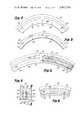
- FIG. 4is a fragmentary sectional view, on an enlarged scale, showing the pocket detail of the sealing rings
- FIG. 5is a view taken on line 5--5 of FIG. 4;
- FIG. 6is a view, similar to FIG. 5 showing the overlap of pockets in the sealing faces.
- a housing 10 having housing parts 12 and 14, suitably joined, as by studs or the like (not shown)has a cavity 16 through which a shaft 18 extends.
- One end of the shaftmay be connected to a pump or the like (not shown) while the other end of the shaft may be connected to a motor (also not shown).
- the cavity 16usually contains a fluid, such as water or oil.
- a mechanical seal assemblygenerally identified as 20, is provided.
- an O-ring seal ring 22is received in a circular groove 24 in the housing part 14; the groove could be in the housing part 12 if desired.
- the shaft 18has a first section 26 of one diameter and a second section 28 of a smaller diameter providing an annular shoulder 30 therebetween.
- the mechanical seal assembly 20comprises a rotating seal subassembly 32 and a stationary or nonrotating seal subassembly 34.
- the rotating seal subassembly 32comprises a spring holder 36, a plurality of coil springs 38, a U-cup follower 40, a rotating sealing ring 42 having a facing 44 thereon, and a resilient gasket 46 between the U-cup follower 40 and the sealing ring 42.
- the spring holder 36is an annular member encircling the shaft section 26 and has a plurality of circumferentially spaced spring cavities 48 therein which, with an annular skirt 50 of the U-cup follower 40, form a plurality of spring pockets 52, each of which receives a spring 38.
- the spring holderis fixed for rotation with the shaft 18 by means of a key 54 received in keyways 56 and 58 machined in the shaft 18 and spring holder 36, respectively.
- a split retaining ring 60is received in a groove 62 in the shaft 18 and in a groove 64 in the spring holder.
- the U-cup follower 40is provided with an axial groove 66 which receives a headed drive pin 68 received in a suitable opening 70 in the spring holder, thus coupling the holder and the follower together for rotation with the shaft 18.
- the U-cup follower 40has an annular nose portion 72 received in an annular groove 74 in the back of the rotating sealing ring 42, and the gasket 46 is located between the nose portion and the back of the sealing ring 42.
- a tang 76, formed in the sealing ring 42,extends into and is received in the groove 66 in the U-cup follower 40 to couple the rotating sealing ring 42 to the shaft 18 for rotation therewith.
- the facing 44 on the front of the rotating sealing ringis a hard, wear surface, as will be later described.
- the stationary sealing ring subassembly 34is an annular member encircling the shaft portion 28 and comprises a sealing ring 78 received in an annular recess 80 in the housing portion 14.
- a drive pin 82extends from the ring 78 and is received in an open-ended groove 84 in the housing portion 14 to lock the ring 78 against rotation with the shaft 18, yet permit the easy disassembly of the subassembly for repair or cleaning, as is necessary.
- An O-ring 86is located in an annular cavity at the rear in the ring 78 to substantially prevent the leakage of fluid to a location behind the ring 78 from the cavity 16.
- the sealing rings 42 and 78have engaging sealing faces 88 and 90, respectively, which are relatively rotatable with respect to one another, the face 88 being on the facing 44 of the ring 42.
- the sealing face 88(see especially FIGS. 4, 5 and 6) on the facing 44 is provided with a plurality of generally evenly, circumferentially spaced outer pockets 92 on an outer annular bolt area 94, and a plurality of generally evenly, circumferentially spaced inner pockets 96 on an inner annular bolt area 98.
- the pockets 92 and 96are staggered with respect to one another.
- the sealing face 90is provided with a plurality of generally evenly, circumferentially spaced outer pockets 100 on an outer annular bolt area 102 and a plurality of generally evenly, circumferentially spaced inner pockets 104 on an inner annular bolt area 106.
- the pockets 100 and 104are staggered with respect to one another.
- the outer bolt areas 94 and 102overlap one another.
- the outer bolt area 102overlaps the inner bolt area 98, and the inner bolt areas 98 and 106 overlap one another.
- a pocket 92communicates with a pocket 100; at another position, a pocket 100 communicates with a pocket 96; and, at still another position, a pocket 96 communicates with a pocket 104.
- fluid trapped in pockets 92is transferred to pockets 100, which in turn is transferred to pockets 96, which in turn is transferred to pockets 104 and then finds its way through the sealing faces to a zone of lower pressure in the housing 14.
- the faces of the sealing ringare exposed to the fluid trapped in the pockets, providing positive lubrication of the seal faces. Because of the flow of the fluid across the faces, the faces are also cooled.
- the sealing rings 42 and 78can be made of conventional materials, such as, for example, stainless steel and graphite, respectively.
- the facing 44is a wear-resistant material, such as stellite or the like, which can be replaced if worn or damaged. This also permits the use of less expensive material for the sealing ring 42.
Landscapes
- Engineering & Computer Science (AREA)
- General Engineering & Computer Science (AREA)
- Mechanical Engineering (AREA)
- Mechanical Sealing (AREA)
- Rotary Pumps (AREA)
Abstract
Description
Claims (8)
Priority Applications (10)
| Application Number | Priority Date | Filing Date | Title |
|---|---|---|---|
| US05/566,874US3957276A (en) | 1975-04-10 | 1975-04-10 | Mechanical seal with pressurized lubrication pockets |
| CA247,424ACA1057326A (en) | 1975-04-10 | 1976-03-09 | Mechanical seal with pressurized lubrication pockets |
| AU12036/76AAU492260B2 (en) | 1975-04-10 | 1976-03-16 | Mechanical seal with pressurized lubrication pockets |
| NLAANVRAGE7602767,ANL177708C (en) | 1975-04-10 | 1976-03-17 | SLIDING SEAL. |
| GB10741/76AGB1494595A (en) | 1975-04-10 | 1976-03-17 | Mechanical seal with pressurised lubrication pockets |
| JP51031522AJPS5854309B2 (en) | 1975-04-10 | 1976-03-24 | Mechanical seal with pressurized lubrication pocket |
| SE7604165ASE423568B (en) | 1975-04-10 | 1976-04-08 | MECHANICAL SEALING UNIT ON A ROTARY AXLE |
| DE2615606ADE2615606C2 (en) | 1975-04-10 | 1976-04-09 | Mechanical seal |
| FR7610579AFR2307199A1 (en) | 1975-04-10 | 1976-04-09 | MECHANICAL SEAL ASSEMBLY TO ENSURE THE TIGHTNESS OF A ROTATING SHAFT IN RELATION TO A HOUSING |
| CA311,145ACA1064986A (en) | 1975-04-10 | 1978-09-12 | Mechanical seal with pressurized lubrication pockets |
Applications Claiming Priority (1)
| Application Number | Priority Date | Filing Date | Title |
|---|---|---|---|
| US05/566,874US3957276A (en) | 1975-04-10 | 1975-04-10 | Mechanical seal with pressurized lubrication pockets |
Publications (1)
| Publication Number | Publication Date |
|---|---|
| US3957276Atrue US3957276A (en) | 1976-05-18 |
Family
ID=24264761
Family Applications (1)
| Application Number | Title | Priority Date | Filing Date |
|---|---|---|---|
| US05/566,874Expired - LifetimeUS3957276A (en) | 1975-04-10 | 1975-04-10 | Mechanical seal with pressurized lubrication pockets |
Country Status (8)
| Country | Link |
|---|---|
| US (1) | US3957276A (en) |
| JP (1) | JPS5854309B2 (en) |
| CA (1) | CA1057326A (en) |
| DE (1) | DE2615606C2 (en) |
| FR (1) | FR2307199A1 (en) |
| GB (1) | GB1494595A (en) |
| NL (1) | NL177708C (en) |
| SE (1) | SE423568B (en) |
Cited By (20)
| Publication number | Priority date | Publication date | Assignee | Title |
|---|---|---|---|---|
| US4099728A (en)* | 1977-10-17 | 1978-07-11 | Borg-Warner Corporation | Mechanical seal assembly |
| US4103907A (en)* | 1975-06-09 | 1978-08-01 | Hitachi, Ltd. | Mechanical seal |
| US4177608A (en)* | 1978-01-16 | 1979-12-11 | Roto-Finish Company, Inc. | Finishing apparatus embodying improved seal and method |
| US4407512A (en)* | 1976-01-02 | 1983-10-04 | John Crane-Houdaille, Inc. | High pressure rotary mechanical seal |
| US4426092A (en) | 1981-10-23 | 1984-01-17 | Borg-Warner Corporation | Mechanical seal assembly |
| US4464580A (en)* | 1981-04-07 | 1984-08-07 | Escher Wyss Limited | Hydro-electric turbo-machine |
| US4491331A (en)* | 1981-12-23 | 1985-01-01 | Hughes Tool Company | Grooved mechanical face seal |
| US5368314A (en)* | 1986-10-28 | 1994-11-29 | Pacific Wietz Gmbh & Co. Kg | Contactless pressurizing-gas shaft seal |
| US5632435A (en)* | 1992-05-27 | 1997-05-27 | Sulzer-Escher Wyss Ag | Process for the production of a soldered joint |
| US5755817A (en)* | 1995-02-06 | 1998-05-26 | Sundstrand Corporation | Hydrostatic seal |
| EP0870956A1 (en)* | 1995-11-10 | 1998-10-14 | Nikuni Machinery Industrial Co., Ltd. | Mechanical seal unit |
| EP0989343A1 (en)* | 1998-09-18 | 2000-03-29 | EAGLE INDUSTRY Co., Ltd. | Rotary ring and mechanical seal using the same |
| US6446976B1 (en) | 2000-09-06 | 2002-09-10 | Flowserve Management Company | Hydrodynamic face seal with grooved sealing dam for zero-leakage |
| US6616144B2 (en)* | 2000-12-26 | 2003-09-09 | Visteon Global Technologies, Inc. | Mechanical seal with embedded lubrication |
| US20040062624A1 (en)* | 2002-09-26 | 2004-04-01 | Intel Corporation | Vented cold ring, processes, and methods of using |
| US20060220322A1 (en)* | 2005-04-04 | 2006-10-05 | Je Pistons, Inc. | Replenishment pockets on piston rings for the prevention of microwelding |
| WO2021190802A1 (en)* | 2020-03-24 | 2021-09-30 | Eagleburgmann Germany Gmbh & Co. Kg | Slide ring seal with improved groove arrangement |
| US20230167905A1 (en)* | 2020-04-22 | 2023-06-01 | Eagle Industry Co., Ltd. | Pair of sliding components |
| US12140179B2 (en) | 2020-03-26 | 2024-11-12 | Eagle Industry Co., Ltd. | Sliding component |
| CN115298463B (en)* | 2020-03-24 | 2025-10-10 | 伊格尔博格曼德国有限公司 | Slide ring seal with improved groove arrangement |
Families Citing this family (6)
| Publication number | Priority date | Publication date | Assignee | Title |
|---|---|---|---|---|
| ZA81208B (en)* | 1980-01-17 | 1982-01-27 | M Marsh | Mechanical seal |
| JPS6226713U (en)* | 1985-08-01 | 1987-02-18 | ||
| DE3627052A1 (en)* | 1986-08-09 | 1988-02-18 | Pacific Wietz Gmbh & Co Kg | Gas sealing arrangement for a shaft |
| US6189896B1 (en) | 1999-04-08 | 2001-02-20 | Caterpillar Inc. | Controlled leakage rotating seal ring with elements for receiving and holding a lubricant on a face thereof |
| US8740224B2 (en)* | 2012-02-28 | 2014-06-03 | General Electric Company | Seal assembly for a turbomachine |
| DE102019219422A1 (en)* | 2019-12-12 | 2021-06-17 | Eagleburgmann Germany Gmbh & Co. Kg | Mechanical seal with monitoring function and procedure for this |
Citations (8)
| Publication number | Priority date | Publication date | Assignee | Title |
|---|---|---|---|---|
| US2247505A (en)* | 1939-01-13 | 1941-07-01 | Joseph H Kohler | Seal |
| GB735250A (en)* | 1953-03-03 | 1955-08-17 | Henschel & Sohn Ges Mit Beschr | Rotary shaft seals |
| US3147013A (en)* | 1961-02-10 | 1964-09-01 | Borg Warner | Dry gas seal |
| US3227463A (en)* | 1959-02-27 | 1966-01-04 | Borg Warner | Mechanical seal |
| DE1470389A1 (en)* | 1964-02-12 | 1969-10-02 | Union Carbide Corp | Process for the preparation of azabicycloheptane derivatives |
| US3628799A (en)* | 1970-01-19 | 1971-12-21 | Borg Warner | Mechanical seal assembly with leakage control |
| US3638957A (en)* | 1970-03-19 | 1972-02-01 | Borg Warner | Mechanical seal with lubricating means |
| US3640541A (en)* | 1970-06-12 | 1972-02-08 | Koppers Co Inc | Hydrodynamic lift-type face seal |
Family Cites Families (2)
| Publication number | Priority date | Publication date | Assignee | Title |
|---|---|---|---|---|
| DE574210C (en)* | 1931-05-19 | 1933-04-10 | Sulzer Akt Ges Geb | Slip ring seal for rotating shafts |
| DE2341431A1 (en)* | 1972-12-26 | 1974-06-27 | Goritsky Boris Sergeewitsch | MECHANICAL SEAL |
- 1975
- 1975-04-10USUS05/566,874patent/US3957276A/ennot_activeExpired - Lifetime
- 1976
- 1976-03-09CACA247,424Apatent/CA1057326A/ennot_activeExpired
- 1976-03-17GBGB10741/76Apatent/GB1494595A/ennot_activeExpired
- 1976-03-17NLNLAANVRAGE7602767,Apatent/NL177708C/ennot_activeIP Right Cessation
- 1976-03-24JPJP51031522Apatent/JPS5854309B2/ennot_activeExpired
- 1976-04-08SESE7604165Apatent/SE423568B/ennot_activeIP Right Cessation
- 1976-04-09DEDE2615606Apatent/DE2615606C2/ennot_activeExpired
- 1976-04-09FRFR7610579Apatent/FR2307199A1/enactiveGranted
Patent Citations (8)
| Publication number | Priority date | Publication date | Assignee | Title |
|---|---|---|---|---|
| US2247505A (en)* | 1939-01-13 | 1941-07-01 | Joseph H Kohler | Seal |
| GB735250A (en)* | 1953-03-03 | 1955-08-17 | Henschel & Sohn Ges Mit Beschr | Rotary shaft seals |
| US3227463A (en)* | 1959-02-27 | 1966-01-04 | Borg Warner | Mechanical seal |
| US3147013A (en)* | 1961-02-10 | 1964-09-01 | Borg Warner | Dry gas seal |
| DE1470389A1 (en)* | 1964-02-12 | 1969-10-02 | Union Carbide Corp | Process for the preparation of azabicycloheptane derivatives |
| US3628799A (en)* | 1970-01-19 | 1971-12-21 | Borg Warner | Mechanical seal assembly with leakage control |
| US3638957A (en)* | 1970-03-19 | 1972-02-01 | Borg Warner | Mechanical seal with lubricating means |
| US3640541A (en)* | 1970-06-12 | 1972-02-08 | Koppers Co Inc | Hydrodynamic lift-type face seal |
Cited By (25)
| Publication number | Priority date | Publication date | Assignee | Title |
|---|---|---|---|---|
| US4103907A (en)* | 1975-06-09 | 1978-08-01 | Hitachi, Ltd. | Mechanical seal |
| US4407512A (en)* | 1976-01-02 | 1983-10-04 | John Crane-Houdaille, Inc. | High pressure rotary mechanical seal |
| US4099728A (en)* | 1977-10-17 | 1978-07-11 | Borg-Warner Corporation | Mechanical seal assembly |
| US4177608A (en)* | 1978-01-16 | 1979-12-11 | Roto-Finish Company, Inc. | Finishing apparatus embodying improved seal and method |
| US4464580A (en)* | 1981-04-07 | 1984-08-07 | Escher Wyss Limited | Hydro-electric turbo-machine |
| US4426092A (en) | 1981-10-23 | 1984-01-17 | Borg-Warner Corporation | Mechanical seal assembly |
| US4491331A (en)* | 1981-12-23 | 1985-01-01 | Hughes Tool Company | Grooved mechanical face seal |
| US5368314A (en)* | 1986-10-28 | 1994-11-29 | Pacific Wietz Gmbh & Co. Kg | Contactless pressurizing-gas shaft seal |
| US5632435A (en)* | 1992-05-27 | 1997-05-27 | Sulzer-Escher Wyss Ag | Process for the production of a soldered joint |
| US5755817A (en)* | 1995-02-06 | 1998-05-26 | Sundstrand Corporation | Hydrostatic seal |
| EP0870956A1 (en)* | 1995-11-10 | 1998-10-14 | Nikuni Machinery Industrial Co., Ltd. | Mechanical seal unit |
| US6485021B1 (en) | 1995-11-10 | 2002-11-26 | Nikuni Machinery Ind Co | Mechanical seal unit with temporarily connecting inlet and outlet grooves |
| US6425583B1 (en)* | 1998-09-18 | 2002-07-30 | Eagle Industry Company, Limited | Rotary ring and mechanical seal using the same |
| EP0989343A1 (en)* | 1998-09-18 | 2000-03-29 | EAGLE INDUSTRY Co., Ltd. | Rotary ring and mechanical seal using the same |
| US6446976B1 (en) | 2000-09-06 | 2002-09-10 | Flowserve Management Company | Hydrodynamic face seal with grooved sealing dam for zero-leakage |
| US6616144B2 (en)* | 2000-12-26 | 2003-09-09 | Visteon Global Technologies, Inc. | Mechanical seal with embedded lubrication |
| US20040062624A1 (en)* | 2002-09-26 | 2004-04-01 | Intel Corporation | Vented cold ring, processes, and methods of using |
| US20060220322A1 (en)* | 2005-04-04 | 2006-10-05 | Je Pistons, Inc. | Replenishment pockets on piston rings for the prevention of microwelding |
| WO2021190802A1 (en)* | 2020-03-24 | 2021-09-30 | Eagleburgmann Germany Gmbh & Co. Kg | Slide ring seal with improved groove arrangement |
| CN115298463A (en)* | 2020-03-24 | 2022-11-04 | 伊格尔博格曼德国有限公司 | Slip ring seal with improved groove arrangement |
| US20230194000A1 (en)* | 2020-03-24 | 2023-06-22 | Eagleburgmann Germany Gmbh & Co. Kg | Mechanical seal with improved groove arrangement |
| US12000488B2 (en)* | 2020-03-24 | 2024-06-04 | Eagleburgmann Germany Gmbh & Co. Kg | Mechanical seal with improved groove arrangement |
| CN115298463B (en)* | 2020-03-24 | 2025-10-10 | 伊格尔博格曼德国有限公司 | Slide ring seal with improved groove arrangement |
| US12140179B2 (en) | 2020-03-26 | 2024-11-12 | Eagle Industry Co., Ltd. | Sliding component |
| US20230167905A1 (en)* | 2020-04-22 | 2023-06-01 | Eagle Industry Co., Ltd. | Pair of sliding components |
Also Published As
| Publication number | Publication date |
|---|---|
| DE2615606C2 (en) | 1982-03-11 |
| FR2307199A1 (en) | 1976-11-05 |
| NL7602767A (en) | 1976-10-12 |
| NL177708B (en) | 1985-06-03 |
| SE423568B (en) | 1982-05-10 |
| JPS5854309B2 (en) | 1983-12-03 |
| CA1057326A (en) | 1979-06-26 |
| SE7604165L (en) | 1976-10-11 |
| GB1494595A (en) | 1977-12-07 |
| JPS51121649A (en) | 1976-10-25 |
| FR2307199B1 (en) | 1981-10-09 |
| AU1203676A (en) | 1977-09-22 |
| DE2615606A1 (en) | 1976-10-21 |
| NL177708C (en) | 1985-11-01 |
Similar Documents
| Publication | Publication Date | Title |
|---|---|---|
| US3957276A (en) | Mechanical seal with pressurized lubrication pockets | |
| US3638957A (en) | Mechanical seal with lubricating means | |
| US2824759A (en) | Liquid cooled seal | |
| US3612548A (en) | Mechanical seal spring holder | |
| US7377518B2 (en) | Mechanical seal ring assembly with hydrodynamic pumping mechanism | |
| US4511149A (en) | Mechanical seal with cylindrical balance sleeve | |
| US4323255A (en) | Mechanical seal with eccentric seal faces | |
| US3200615A (en) | Sealing element | |
| EP0013678B1 (en) | Self aligning spiral groove face seal | |
| US5516118A (en) | Circumferential hydrodynamic seals for sealing a bidirectionally rotatable member | |
| US3926442A (en) | Sliding ring seal | |
| KR0125009B1 (en) | Sealing ring device for impeller pump | |
| US3628799A (en) | Mechanical seal assembly with leakage control | |
| US3356378A (en) | Sealing ring assembly for a mechanical seal | |
| US2470419A (en) | Balanced, cooled, and lubricated rotary seal | |
| US3388913A (en) | Mechanical seal | |
| US3486760A (en) | Mechanical seal assembly with lubricating means | |
| US3970320A (en) | Mechanical seal with thermo-cooling | |
| US3227463A (en) | Mechanical seal | |
| US5941531A (en) | Double gas seal having an improved bellows arrangement | |
| US4266786A (en) | Mechanical seal assembly | |
| US3218085A (en) | Mechanical seal assembly with anti-coking device | |
| US3889960A (en) | Cooling seal | |
| US2432684A (en) | Liquid cooled seal | |
| CA2032643C (en) | Quenching mechanism of shaft seal for slurry pumps |
Legal Events
| Date | Code | Title | Description |
|---|---|---|---|
| AS | Assignment | Owner name:BORG-WARNER INDUSTRIAL PRODUCTS, INC., 200 OCEANGA Free format text:ASSIGNMENT OF ASSIGNORS INTEREST.;ASSIGNOR:BORG-WARNER CORPORATION;REEL/FRAME:004745/0469 Effective date:19870514 Owner name:CITIBANK, N.A., 641 LEXINGTON AVE., NEW YORK, NY 1 Free format text:SECURITY INTEREST;ASSIGNOR:BORG-WARNER INDUSTRIAL PRODUCTS, INC.,;REEL/FRAME:004745/0480 Effective date:19870520 Owner name:BORG-WARNER INDUSTRIAL PRODUCTS, INC., CALIFORNIA Free format text:ASSIGNMENT OF ASSIGNORS INTEREST;ASSIGNOR:BORG-WARNER CORPORATION;REEL/FRAME:004745/0469 Effective date:19870514 Owner name:CITIBANK, N.A., NEW YORK Free format text:SECURITY INTEREST;ASSIGNOR:BORG-WARNER INDUSTRIAL PRODUCTS, INC.,;REEL/FRAME:004745/0480 Effective date:19870520 | |
| AS | Assignment | Owner name:BW/IP INTERNATIONAL, INC., ("BW/IP"), 200 OCEANGAT Free format text:ASSIGNMENT OF ASSIGNORS INTEREST. EFFECTIVE MAY 20, 1987;ASSIGNOR:BORG-WARNER CORPORATION, A DE. CORP.;REEL/FRAME:004836/0834 Effective date:19880215 Owner name:BW/IP INTERNATIONAL, INC., ("BW/IP"),A CORP. OF DE Free format text:ASSIGNMENT OF ASSIGNORS INTEREST;ASSIGNOR:BORG-WARNER CORPORATION, A DE. CORP.;REEL/FRAME:004836/0834 Effective date:19880215 | |
| AS | Assignment | Owner name:CITIBANK, N.A., NEW YORK Free format text:RELEASED BY SECURED PARTY;ASSIGNOR:BW/IP INTERNATIONAL INC. (FORMERLY KNOWN AS BORG-WARNER INDUSTRIAL PRODUCTS, INC.);REEL/FRAME:006376/0881 Effective date:19910831 |