US3954108A - Occlusion clip and instrument for applying same - Google Patents
Occlusion clip and instrument for applying sameDownload PDFInfo
- Publication number
- US3954108A US3954108AUS05/501,079US50107974AUS3954108AUS 3954108 AUS3954108 AUS 3954108AUS 50107974 AUS50107974 AUS 50107974AUS 3954108 AUS3954108 AUS 3954108A
- Authority
- US
- United States
- Prior art keywords
- clip
- jaw means
- jaw
- instrument
- occlusion
- Prior art date
- Legal status (The legal status is an assumption and is not a legal conclusion. Google has not performed a legal analysis and makes no representation as to the accuracy of the status listed.)
- Expired - Lifetime
Links
- 210000003101oviductAnatomy0.000claimsabstractdescription13
- 239000000463materialSubstances0.000claimsabstractdescription5
- 210000001113umbilicusAnatomy0.000claimsdescription6
- 230000000295complement effectEffects0.000claimsdescription5
- 238000003780insertionMethods0.000claimsdescription3
- 230000037431insertionEffects0.000claimsdescription3
- 238000013459approachMethods0.000claimsdescription2
- 230000003287optical effectEffects0.000description10
- 230000008901benefitEffects0.000description5
- 210000003484anatomyAnatomy0.000description4
- 238000000926separation methodMethods0.000description4
- 230000001954sterilising effectEffects0.000description4
- 238000004659sterilization and disinfectionMethods0.000description4
- 238000010276constructionMethods0.000description3
- 230000000694effectsEffects0.000description3
- 238000005286illuminationMethods0.000description3
- 230000007246mechanismEffects0.000description3
- 230000004048modificationEffects0.000description3
- 238000012986modificationMethods0.000description3
- 238000005452bendingMethods0.000description2
- 210000004204blood vesselAnatomy0.000description2
- 230000001681protective effectEffects0.000description2
- 206010016654FibrosisDiseases0.000description1
- 229910000831SteelInorganic materials0.000description1
- 210000003815abdominal wallAnatomy0.000description1
- 230000009471actionEffects0.000description1
- 230000015572biosynthetic processEffects0.000description1
- 238000013461designMethods0.000description1
- 230000004761fibrosisEffects0.000description1
- 230000000968intestinal effectEffects0.000description1
- 238000000034methodMethods0.000description1
- 230000000704physical effectEffects0.000description1
- 230000004044responseEffects0.000description1
- 239000010959steelSubstances0.000description1
- 229910052715tantalumInorganic materials0.000description1
- GUVRBAGPIYLISA-UHFFFAOYSA-Ntantalum atomChemical compound[Ta]GUVRBAGPIYLISA-UHFFFAOYSA-N0.000description1
- 210000004291uterusAnatomy0.000description1
- 210000001177vas deferenAnatomy0.000description1
- 210000003462veinAnatomy0.000description1
Images


Classifications
- A—HUMAN NECESSITIES
- A61—MEDICAL OR VETERINARY SCIENCE; HYGIENE
- A61B—DIAGNOSIS; SURGERY; IDENTIFICATION
- A61B1/00—Instruments for performing medical examinations of the interior of cavities or tubes of the body by visual or photographical inspection, e.g. endoscopes; Illuminating arrangements therefor
- A61B1/303—Instruments for performing medical examinations of the interior of cavities or tubes of the body by visual or photographical inspection, e.g. endoscopes; Illuminating arrangements therefor for the vagina, i.e. vaginoscopes
- A—HUMAN NECESSITIES
- A61—MEDICAL OR VETERINARY SCIENCE; HYGIENE
- A61F—FILTERS IMPLANTABLE INTO BLOOD VESSELS; PROSTHESES; DEVICES PROVIDING PATENCY TO, OR PREVENTING COLLAPSING OF, TUBULAR STRUCTURES OF THE BODY, e.g. STENTS; ORTHOPAEDIC, NURSING OR CONTRACEPTIVE DEVICES; FOMENTATION; TREATMENT OR PROTECTION OF EYES OR EARS; BANDAGES, DRESSINGS OR ABSORBENT PADS; FIRST-AID KITS
- A61F6/00—Contraceptive devices; Pessaries; Applicators therefor
- A61F6/20—Vas deferens occluders; Fallopian occluders
- A61F6/202—Means specially adapted for ligaturing, compressing or clamping of oviduct or vas deferens
- A61F6/204—Clamp applying devices
Definitions
- the present inventionrelates to an instrument to apply an occlusion clip.
- HemoclipA clip designated "Hemoclip” is known in the art which consists of a thin wire bent into approximately U-shape. While this Hemoclip has been used with some success, certain problems nevertheless exist with this prior art type of occlusion clip because, if the wire is applied too tightly, it will cut into the tubular structure. Furthermore, if the wire of this prior art clip is too narrow, as is the case, then the specific pressure becomes excessively high. Since a certain width is necessary to assure a satisfactory occlusion, it is customary to apply two or three of these so-called "Hemoclips" to a given anatomical tubular structure.
- LaparoscopeAn instrument called "Laparoscope” for purposes of sterilization by cauterizing fallopian tubes. After causing ballooning of the abdominal wall, a narrow slit is made through the umbilicus to thereafter insert the Laparoscope, and with the assist of fiber-optics, cauterization is effected.
- this method of sterilizationis fraught with certain dangers as some difficulties exist in controlling the degree and extent of cauterization in order to avoid accidental burning of adjacent parts, such as intestinal portions.
- the present inventionis concerned with the task of providing an occlusion clip which includes means to lock the clip in position during its application so that the clip cannot come off the instrument used for applying the same.
- the instrument in accordance with the present inventionis provided with relatively movable jaws at the free end of a tubular member adapted to be inserted through an opening, for example, through the umbilicus whereby the jaws are provided with means to lock the occlusion clip in position while being inserted into the opening formed in the human body for eventual emplacement over the fallopian tubes or the like.
- the occlusion clip in accordance with the present inventionis securely held in position until actually installed over the anatomical tubular structure.
- An advantage of the instrument in accordance with the present inventionresides in the particular location of the fulcrum for the movable jaw to assure a closing of the free end of the lower jaw first, thereby assuring an occlusion without cutting into any tissues.
- Another feature of the present inventionresides in the simplicity of the instrument used for applying the occlusion clip which has a convenient pistol grip and permits a good view through its tubular member even when the jaws are closed, thus enabling accurate control in the positioning and application of the occlusion clip.
- a further object of the present inventionresides in an instrument for applying an occlusion clip same which will provide occlusion at spaced points to minimize the likelihood of eventual failure of the occlusion.
- Still another object of the present inventionresides in an apparatus for applying an occlusion clip of the type described above which permits permeation likely to encourage fibrosis to assure a permanent interruption in the anatomical tubular structure.
- Still a further object of the present inventionresides in a combined occlusion clip and instrument for applying the same which assure reliable locking of the clip onto the instrument during the operation.
- Another object of the present inventionresides in an instrument for applying the occlusion clip of the present invention which is simple in construction, reliable in operation and permits easy handling by the availability of an optical viewing system enabling the doctor to visually follow the positioning and application of the clip throughout the entire operation.
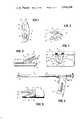
- FIG. 1is a plan view of an occlusion clip blank in accordance with the present invention
- FIG. 2is a perspective view of a clip formed from the blank of FIG. 1 by bending the blank back upon itself into a configuration ready for insertion into the open jaws of the instrument;
- FIG. 3is a somewhat schematic side view illustrating the application of the occlusion clip shown in FIG. 2 on an anatomical tubular structure;
- FIG. 4is a fragmentary view showing the occlusion clip clamped on the anatomical tubular structure of FIG. 3;
- FIG. 3is a side view of an instrument in accordance with the present invention for applying the occlusion clip of FIG. 2 on the anatomical tubular structure;
- FIG. 6is a fragmentary view, partially in longitudinal cross section, through certain parts of the instrument of FIG. 5;
- FIG. 7is an exploded perspective view of the front part of the instrument of FIGS. 5 and 6;
- FIG. 8is an enlarged side view of the front part of the instrument of FIG. 5 illustrating the jaw portions thereof;
- FIG. 9is a perspective, exploded view of the rear part of the instrument shown in FIG. 5;
- FIG. 10is a cross-sectional view, on an enlarged scale, through the instrument of the present invention taken along line X--X of FIG. 6;
- FIG. 11is a perspective view, on an enlarged scale, of the front part of the instrument in accordance with the present invention.
- FIG. 12is a perspective view of the occlusion clip in relation to the anatomical tubular structure at the beginning of its application;
- FIG. 13is a perspective view, similar to FIG. 12 and showing the relationship of the occlusion clip to the anatomical tubular structure as the application proceeds;
- FIG. 14is a perspective view of the front part of a modified embodiment of an instrument in accordance with the present invention.
- FIGS. 15a and 15bare schematic side views comparing the installed clip of the present invention with the installed clip of the prior art, respectively.
- the occlusion clip blank generally designated by reference numeral 10is in the form of a unitary structure which includes two lateral portions 24 and 25, constituting in effect two occlusion clip members spatially separated from one another, a connecting portion 26 at the upper end, as viewed in FIG. 1 which connects the side portions 24 and 25 and a connecting portion 27 connecting the side portions 24 and 25 at the lower end.
- An indexing aperture 14is also provided in the lower connecting portion 27 which is intended to engage with an indexing projection 38 (FIGS. 3, 8, and 11) provided on the fixed jaw 34 of the instrument of this invention for positioning the occlusion clip 10 in relation to the instrument and to thereby lock the same in position.
- the occlusion clip of FIGS. 1 and 2provides in effect for an elongated opening or hiatus 12 defining a herniating divider portion 18 thereby separates this hiatus 12 from the indexing aperture 14.
- the occlusion clip blank 10made of suitable flexible material is bent back upon itself about the flex line 16 to provide two half portions generally designated by reference numerals 20 and 22 such as illustrated in FIG. 2.
- the blank 10should thereby be bent only to such an extent that the two portions 20 and 22 subtend therebetween an angle slightly larger than the angle of the two jaws 32 and 34 when in the fully opened position as shown in FIG. 3 so that the occlusion clip will securely lock in place by engagement of its aperture 14 with the nose-like indexing projection 38.
- portion 22may also be appropriate to impart a curved configuration to the portion 22 when bending the blank 10 back upon itself as shown in FIG. 3. Additionally, it may also be convenient to permit the portion 22 to be slightly longer than the portion 20, for example, by an amount of about 1/24 to 1/32 inch.
- the blank 10in lieu of the approximately oval shape of the blank 10 it is also possible to make the blank 10 of any other configuration, for example, of substantially rectangular configuration, in which case the occlusion clip portions 24 and 25 would be parallel to one another while the end portions 26 and 27 as well as the separating portion 18 would be at right angle thereto.
- the instrument for applying the occlusion clipis in the form of an elongated tubular structure generally designated by reference numeral 30 (FIG. 5) which is provided at the left end thereof as viewed in FIG. 5 with jaws 32 and 34.
- the jaw 34is formed as an integral part of the tubular member 50 adjacent the left end thereof as viewed in FIG. 5.
- the jaw 32is pivotal about an axis 52 (FIGS. 7 and 11) between its open, clip receiving position (shown in full line in FIG. 8) and the clip-applying position shown in dash line in FIG. 8.
- the closing movement of the jaw 32is such that the free end of the jaws 34 and 32 will come into abutment against one another while also forming a narrow tapering space increasing in the direction toward the gripping portion generally designated by reference numeral 108.
- This particular closing movementassures that the free ends constituted by the connecting portions 26 and 27 are closed before the entire occlusion clip is more or less flattened out, thereby preventing a slipping off of the occlusion clip from the anatomical tubular structure such as a fallopian tube, when being applied and assuring other advantages as will be described more fully hereinafter by reference to FIGS. 15a and 15b.
- the handleOn the side of the tubular member 50, opposite the jaws 34 and 32, i.e., on the right side as viewed in FIG. 5 is provided the handle generally designated by reference numeral 108 which includes an actuating member 54 in the form of a trigger, connected with the movable jaw 32 by way of the control linkage as will be described more fully hereinafter.
- a separate tube 58(FIG. 6) is provided on the inside of the tubular structure 50 for receiving and positioning an optical device of conventional construction, the front end of which is schematically indicated and designated in FIG. 6 by reference numeral 60. At its opposite end, the tube 58 is provided with a conventional eye piece 60' which may be adjustable if so desired.
- the viewing means 58, 60 and 60'permits the user of the instrument to view between the opened jaws as well as between the separated clamping portions 24 and 25 of the occlusion clip when in the initial position during the application as shown in FIG. 3, thus permitting a continuous viewing of the insertion of the instrument through the opening in the umbilicus and during the positioning thereof over the fallopian tube.
- the instrumentalso includes further means to produce a light beam 61 (FIG.
- illuminating meansmay be of any conventional type, for example, in the form of another tube 62 which extends through the tube 50 and includes a light source, for instance in the form of a small lamp designated in FIG. 6 by reference illumination to facilitate the positioning and application of the occlusion clip.
- a light source 64 located at the end of the tube 62it is preferable to use a light source in the form of conventional fiber-optics and constituted by the tube 62 with the primary light source for the fiber-optics located internally or preferably externally at any appropriate place on the instrument. Since such fiber-optical illuminating devices are known as such, a detailed description thereof is dispensed with herein.
- a pair of support projections 68 and 70 for the handle structureare secured to the tube 50 by conventional means. These supporting projections 68 and 70 are thereby located on both sides of an elongated recess 72 in the tube 50.
- the recess 72slidably receives a slidable control member generally designated by reference numeral 74 and enables reciprocation thereof in the axial direction of the tube 50 between the two supporting projections 68 and 70.
- the slidable control member 74includes a U-shaped upper body part formed by leg portions 76 and 76' connected by web portion 77 in such a manner that a substantially U-shaped recess 78 is formed.
- This recess 78is so shaped as to receive the tubular member 62 for the illuminating device so that the slidable control member 74 is guided in its to and fro movement on the tube 62 when the control member is assembled in its position as shown in FIGS. 6 and 10.
- the slidable control member 74includes a pair of depending leg portions 80 and 82 spaced from one another to receive the body portion 84 of the trigger member 54.
- the body portion 84is provided with a rectangular notch 86 to receive a pin 88 which extends across the U-shaped channel between the projecting leg portions 80 and 82.
- the trigger plate 84is further provided with a corner 90 which, as shown in FIG. 6, is adapted to engage with the surface 70' of the supporting projection 70 so that in case of application of a force in the direction of arrow A (FIGS. 6 and 9), the corner 90 will abut at the surface 70' and thus constitutes a fulcrum about which the trigger member 54 will rotate in the counterclockwise direction, thereby imparting a sliding movement to the slidable control member 74 toward the left direction, as viewed in FIG. 6, which is made possible by the pivotal connection 86, 88, between these two parts.
- the camming action between corner 90 and surface 70'translates the force A into sliding movements of the slidable control member 74.
- a return spring 92is interposed between the trigger plate 84 and the relatively stationary support member 70 and engages at its left end in a recess 94 provided in the trigger plate 84 and at the right end in the recess 96 provided in the supporting member 70.
- the handle structure 108further includes a pair of cover plates 98 and 100 (FIGS. 9 and 10), each provided with a recess 102 and 102', recess 102 being shown clearly in FIG. 9.
- the recesses 102 and 102'are intended to receive the leg portions 80 and 82 of the sidable control member l74.
- the cover members 98 and 100are provided with depending plate-like leg portions 104 and 106 which act as guide means for the trigger plate 84 when the parts are in the assembled position thereof as shown in FIG. 10.
- the handle assemblyfurther includes a cover structure generally designated by reference numeral 108 which has a pair of parallel-spaced cover plate portions 110 and 110' connected by means of a rib 112 (FIG. 6).
- cover plates 98 and 100 and the cover plate portions 110 and 110' as well as the rib 112 of the cover structure 108are secured to the support members 68 and 70 by means, for example, of screws which extend through screw holes as indicated.
- any other suitable fastening meansmay also be used to hold the parts in their assembled position.
- the rib 112is also held fast in its proper position by the two-point connection constituted by the pin-type pivotal connection 112' and the screw extending through aligned holes 110a and 112a and the hole 110a' (not shown) in the cover portion 110'.
- the jaw 34is formed as an integral part of the exterior tube 50 adjacent its left end as viewed in FIGS. 5 and 6, and includes inwardly thereof lug portions 114 for pivotally supporting thereon by means of screws or the like the movable jaw 32.
- the lug portions 114which are of approximately partially circular shape, provide guide surfaces 114' for the pivotal movement of the movable jaw member 32 which is also guided along the guide surfaces 114" (FIGS. 8) constituted by the cut-out portions provided in the fixed jaw 34 to accommodate the side members 32' and 32" of the movable jaw 32.
- the fixed jaw 34in addition to the nose-like indexing projection 38 is also provided with an aperture 35.
- the movable jaw 32includes a transverse end portion 116 and spaced side portions 118 and 120 each provided with bearing portions 122 and 124 at the side members 32' and 32" thereof and adapted to engage with the stationary bearing surfaces 114".
- the jaw 32is thereby pivotally supported on the lug portions 114 by any suitable means such as screws.
- Below the bearing surfaces 122 and 124 the leg portions 32' and 32"are provided with opposite aligning recesses 126 and 128 to receive a reciprocal, slidable control member generally designated by reference numeral 130 which is pivotally connected with the side members 32' and 32" by means of a pivot pin 132.
- the slidable control member 130has an exterior configuration 134 at the bottom thereof to permit substantial alignment with and sliding movement along the inner surface of the outer tube 50. Additionally, the slidable control member 130 has an interior cylindrical recess 136 to provide for a substantially cylindrical aperture adjacent the jaw end of the tubular structure 50.
- the slidable control member 130is connected with the slidable control member 74 by means of a pair of elongated members 56 such as steel wires which are sufficiently stiff and rigid to cause the sliding control member 130 to partake in the reciprocation of the sliding control member 74 in response to actuation of the trigger 54.
- the illuminating deviceis in the form of an elongated tubular cable protective structure 62 for conducting by means of a cable disposed therewithin the supply voltage to a small electric bulb arranged at the front end thereof and indicated schematically by reference numeral 64 in FIG. 6.
- a small electric bulbarranged at the front end thereof and indicated schematically by reference numeral 64 in FIG. 6.
- the rear end of the cable protective structure or of the cable itself which extends through the tube 62is bent downwardly as shown at 142 in FIG. 9 to be received between the side plates 110 and 112 so as to be protected thereby and held in position by means of a leaf spring 144 or the like.
- a power supplysuch as a battery can be connected to the lower end at 146 (FIG. 9).
- the light source in the form of a suitable small incandescent high power lamp or the likemay then be located in any suitable place, for example, externally of the tubular member 50, e.g., at the end of the portion 142, thereby obviating the need for the electrical cable and the bulb and the problem of replacing the same if wear occurs.
- the optical device to be used with the instrument of the present inventionis in the form of an elongated structure and includes a number of optical lenses of conventional type as know in the art. Since the optical device, except for its particular location and association with the instrument of the present invention forms no part thereof, a detailed description is dispensed with herein.
- the clipmay be applied under direct continuous vision through the optical system during the operation.
- the movable jaw 32is also provided with an aperture 33 so that continued viewing is made possible even after the free end of the movable jaw 32 abuts at the free end of the fixed jaw 34.
- the occlusion clipis positioned between the jaws as shown in FIG. 3 with the indexing projection 38 engaging in the indexing aperture 14 of the occlusion clip.
- the location of the fallopian tube or other anatomical tubular structurebecomes an easy matter for a trained surgeon. Since the fallopian tube can be observed directly through the opening 12 of the occlusion clip, i.e., through the spacing between the lateral clip portions 24 and 25, it is also easy to properly approach the anatomical tubular structure as well as to ascertain when the clip is in proper position relative thereto as shown in FIG. 12. In this position, the trigger 54 is actuated and the occlusion clip is closed on the tube 40 as shown in FIG. 13.
- the pivot point of the movable jaw 32is slightly eccentric.
- This eccentricityin combination with the configuration of the portion 22 of the occlusion clip which, as mentioned hereinabove may be slightly curved, provides for a safe closing of the clip on the tube without crushing the tube to an extent that might otherwise cause damage or slipping off.
- Thisis a very important feature since the particular angulation of the jaws 32 and 34 and/or the height of the indexing tooth 38 permit that the separation of the occlusion clip arms, in the applied position, can be precisely predetermined. This is illustrated in FIGS.
- FIG. 15a and 15billustrating respectively somewhat schematic side elevational views of a clip in accordance with the present invention and of a clip of the prior art type, both when in the applied condition.
- a predetermined separation or gap gexists between the two arm portions 20 and 22, when applied, within the area receiving the anatomical structure.
- This separation gwhich can be precisely predetermined by the design of the instrument of this invention, i.e., by the eccentricity of the pivot point of the movable jaw 32 and/or the height of the indexing tooth 38, may be about 0.8 mm which has been determined optimum for certain applications, and can be varied in a simple manner, if necessary, to a value greater or smaller than 0.8 mm, for example, to 0.5 mm if the thickness of the anatomical structure or of its tissue walls so demands. This is very important because if a clip is closed fully flat, as is the case in the prior art, illustrated in FIG.
- the opening 12 in the clip 10performs the important function in the applied condition. On the one hand it acts as a pressure relief means and on the other, assists in locking the clip in position on the anatomical structure.
- the openings 33 and 35 in jaws 32 and 34perform similar functions during the application. These two functions are only schematically indicated in dash and dot lines in FIG. 15a, showing the possibility of parts of the tissues of the anatomical structures to pass through opening 12.
- the mutually facing surfaces of the two jaws 32 and 34are flat and parallel to one another, it may also be advantageous to use a different arrangement.
- the surfacesneed not be parallel to one another but may form a slight angle therebetween by appropriate beveling of one or both jaws in such a manner that the separation g is, for example, about 0.8 mm on one side of the clip and say 0.5 mm, on the other side.
- the surfacesneed not necessarily be flat for this purpose.
- the "controlled closure"is still present in the non-parallel arrangement of the jaw surfaces, resulting in the avoidance of the failures of the prior art.
- FIG. 14shows the front end of the instrument with an occlusion clip in the form of two completely separate narrow clip members 150 and 152 positioned relative to the jaws by means of individual indexing means 154 and 156. This will permit the application of entirely separate clips in one and the same operation.
- an indexing means in one of the jawsmay be in the form of a rib which extends transversely to the jaw adjacent the edge thereof operable to engage the edge of the connecting portion 26 left between the side members 24 and 25.
- the instrumentwith jaws extending substantially perpendicular to the longitudinal axis of the tubular structure 50.
- itwill only be necessary to include a prism or the like in the optical system to conduct the light rays around the then existing corner.
- the present inventionfinds particular application for purposes of sterilization in connection with the fallopian tubes, its application is not limited thereto.
- the present inventioncan also be used for ligations, for example, blood vessels or the like.
- the present inventionstill entails the advantage of requiring only a single application in lieu of the need for a repeated application of two or more clips.
- the instrumentthrough the umbilicus has been described, its use is not limited thereto but could be used equally successfully for sterilization after the delivery when the fallopian tubes can be made accessible by merely a small incision due to the enlarged condition of the uterus.
- the instrumentmay be used also for purposes of ligation of vas deferens in males.
- the instrumentcan be simplified by omitting its optical system and/or its light source, thus resulting in a less costly instrument, still entailing the same advantage of "controlled closure" of the clip.
- the instrumentis not limited to the particular actuating mechanism as shown and described but any other actuating mechanism may be equally used which converts the actuating movement into pivotal movement of the movable jaw.
- the tubular structure 50can be omitted and the means for actuating the movable jaw can then be greatly modified and simplified in a conventional manner, substituting another type of actuating mechanism for the one illustrated herein.
- the present inventionis equally applicable under culdoscopy for application through a culdoscope or similar device.
- any suitable material having the requisite physical propertiesmay be used for the occlusion clip in accordance with the present invention, tantalum being among the preferred materials.
Landscapes
- Health & Medical Sciences (AREA)
- Life Sciences & Earth Sciences (AREA)
- Surgery (AREA)
- Reproductive Health (AREA)
- Engineering & Computer Science (AREA)
- Biomedical Technology (AREA)
- Heart & Thoracic Surgery (AREA)
- Animal Behavior & Ethology (AREA)
- General Health & Medical Sciences (AREA)
- Public Health (AREA)
- Veterinary Medicine (AREA)
- Vascular Medicine (AREA)
- Physics & Mathematics (AREA)
- Biophysics (AREA)
- Nuclear Medicine, Radiotherapy & Molecular Imaging (AREA)
- Optics & Photonics (AREA)
- Pathology (AREA)
- Radiology & Medical Imaging (AREA)
- Gynecology & Obstetrics (AREA)
- Medical Informatics (AREA)
- Molecular Biology (AREA)
- Surgical Instruments (AREA)
Abstract
Description
Claims (9)
Priority Applications (1)
| Application Number | Priority Date | Filing Date | Title |
|---|---|---|---|
| US05/501,079US3954108A (en) | 1972-11-03 | 1974-08-27 | Occlusion clip and instrument for applying same |
Applications Claiming Priority (2)
| Application Number | Priority Date | Filing Date | Title |
|---|---|---|---|
| US00303314AUS3856016A (en) | 1972-11-03 | 1972-11-03 | Method for mechanically applying an occlusion clip to an anatomical tubular structure |
| US05/501,079US3954108A (en) | 1972-11-03 | 1974-08-27 | Occlusion clip and instrument for applying same |
Related Parent Applications (1)
| Application Number | Title | Priority Date | Filing Date |
|---|---|---|---|
| US00303314ADivisionUS3856016A (en) | 1972-11-03 | 1972-11-03 | Method for mechanically applying an occlusion clip to an anatomical tubular structure |
Publications (1)
| Publication Number | Publication Date |
|---|---|
| US3954108Atrue US3954108A (en) | 1976-05-04 |
Family
ID=26973387
Family Applications (1)
| Application Number | Title | Priority Date | Filing Date |
|---|---|---|---|
| US05/501,079Expired - LifetimeUS3954108A (en) | 1972-11-03 | 1974-08-27 | Occlusion clip and instrument for applying same |
Country Status (1)
| Country | Link |
|---|---|
| US (1) | US3954108A (en) |
Cited By (102)
| Publication number | Priority date | Publication date | Assignee | Title |
|---|---|---|---|---|
| FR2437820A1 (en)* | 1978-06-29 | 1980-04-30 | Wolf Gmbh Richard | CLAMPS FOR PLACING FASTENING STAPLES ON THE TRUMPS |
| US4242902A (en)* | 1978-05-11 | 1981-01-06 | United States Surgical Corporation | Surgical clip applicator |
| US4414721A (en)* | 1980-11-07 | 1983-11-15 | Hufnagel Charles A | Occlusive clip and applicator for constricting flexible tubular members |
| US4440170A (en)* | 1979-03-06 | 1984-04-03 | Ethicon, Inc. | Surgical clip applying instrument |
| USD284219S (en) | 1983-03-30 | 1986-06-10 | United States Surgical Corporation | Combined surgical occluding and cutting instrument |
| US4602631A (en)* | 1983-09-08 | 1986-07-29 | Noboru Funatsu | Forceps for clamping surgical clips |
| USD286439S (en) | 1984-01-23 | 1986-10-28 | United States Surgical Corporation | Combined surgical occluding and cutting instrument |
| US4635634A (en)* | 1985-07-12 | 1987-01-13 | Santos Manuel V | Surgical clip applicator system |
| US4646740A (en)* | 1981-02-23 | 1987-03-03 | Edward Weck & Co., Inc. | Automatic hemoclip applier |
| US4805618A (en)* | 1985-08-08 | 1989-02-21 | Olympus Optical Co., Ltd. | Oviduct closing apparatus |
| US4951860A (en)* | 1987-12-28 | 1990-08-28 | Edward Weck & Co. | Method and apparatus for storing, dispensing and applying surgical staples |
| US5156608A (en)* | 1990-07-30 | 1992-10-20 | Hans Troidl | Clip applicator for ligature clips |
| US5171250A (en)* | 1987-05-14 | 1992-12-15 | Inbae Yoon | Surgical clips and surgical clip applicator and cutting and transection device |
| US5190560A (en)* | 1991-06-20 | 1993-03-02 | Woods John B | Instrument for ligation and castration |
| USD344334S (en) | 1992-04-15 | 1994-02-15 | Davinci Medical, Inc. | Surgical instrument actuator handle |
| US5300081A (en)* | 1992-10-09 | 1994-04-05 | United States Surgical Corporation | Surgical clip applier having clip advancement control |
| US5382254A (en)* | 1989-07-18 | 1995-01-17 | United States Surgical Corporation | Actuating handle for surgical instruments |
| US5382255A (en)* | 1993-01-08 | 1995-01-17 | United States Surgical Corporation | Apparatus and method for assembly of surgical instruments |
| US5383881A (en)* | 1989-07-18 | 1995-01-24 | United States Surgical Corporation | Safety device for use with endoscopic instrumentation |
| US5395030A (en)* | 1992-06-04 | 1995-03-07 | Olympus Optical Co., Ltd. | Surgical device for stapling and fastening body tissues |
| US5441509A (en)* | 1992-04-28 | 1995-08-15 | Minnesota Mining And Manufacturing Company | Vessel clips |
| US5445167A (en)* | 1987-05-14 | 1995-08-29 | Yoon; Inbae | Methods of applying surgical chips and suture tie devices to bodily tissue during endoscopic procedures |
| US5449365A (en)* | 1992-09-02 | 1995-09-12 | United States Surgical Corporation | Surgical clamp apparatus |
| US5611358A (en)* | 1995-09-08 | 1997-03-18 | Suval; William D. | Method and apparatus for treating varicose veins |
| US5611357A (en)* | 1995-02-09 | 1997-03-18 | Suval; William D. | Method and apparatus for treating varicose veins |
| US5707380A (en)* | 1996-07-23 | 1998-01-13 | United States Surgical Corporation | Anastomosis instrument and method |
| US5758665A (en)* | 1996-11-14 | 1998-06-02 | Suval; William D. | Method for treating varicose veins |
| US5792168A (en)* | 1996-11-14 | 1998-08-11 | Suval; William D. | Apparatus for treating varicose veins |
| US5833696A (en)* | 1996-10-03 | 1998-11-10 | United States Surgical Corporation | Apparatus for applying surgical clips |
| US6024748A (en)* | 1996-07-23 | 2000-02-15 | United States Surgical Corporation | Singleshot anastomosis instrument with detachable loading unit and method |
| US20020019642A1 (en)* | 1996-07-23 | 2002-02-14 | Keith Milliman | Anastomosis instrument and method for performing same |
| US20020177860A1 (en)* | 1996-07-23 | 2002-11-28 | Nicholas David A. | Anastomosis instrument and method |
| US20030120285A1 (en)* | 1997-11-03 | 2003-06-26 | Symbiosis Corporation | Surgical instrument for invagination and fundoplication |
| US20030208213A1 (en)* | 1996-07-23 | 2003-11-06 | Manzo Scott E. | Anastomosis instrument and method for performing same |
| US20030222117A1 (en)* | 2002-05-31 | 2003-12-04 | Orban Joseph P. | End-to-end anastomosis instrument and method for performing same |
| US6663640B2 (en)* | 1997-11-03 | 2003-12-16 | Symbiosis Corporation | End effector for use with a flexible endoscopic surgical instrument for invagination and fundoplication |
| US20040010274A1 (en)* | 2002-07-10 | 2004-01-15 | Manzo Scott E. | Anastomosis instrument and method for performing same |
| US20040092971A1 (en)* | 1996-07-23 | 2004-05-13 | Kevin Sniffin | Anastomosis instrument and method for performing same |
| US20050261642A1 (en)* | 2004-05-21 | 2005-11-24 | Weston Richard S | Flexible reduced pressure treatment appliance |
| US20050277959A1 (en)* | 2004-05-26 | 2005-12-15 | Idx Medical, Ltd. | Apparatus and methods for occluding a hollow anatomical structure |
| US20060289601A1 (en)* | 2003-05-30 | 2006-12-28 | Tyco Healthcare Group, Lp | End-to-end anastomosis instrument and method for performing same |
| US20080296344A1 (en)* | 2007-05-30 | 2008-12-04 | Ethicon Endo-Surgery, Inc. | Surgical Instrument |
| US20080300629A1 (en)* | 2007-05-31 | 2008-12-04 | Wilson-Cook Medical Inc. | Suture lock |
| US20080312670A1 (en)* | 2006-01-11 | 2008-12-18 | Aesculap Ag | Surgical ligature clip |
| US20090270912A1 (en)* | 2008-04-23 | 2009-10-29 | Wilson-Cook Medical Inc. | Tacking device |
| US20100049208A1 (en)* | 2008-08-19 | 2010-02-25 | Wilson-Cook Medical Inc. | Apparatus and methods for removing lymph nodes or anchoring into tissue during a translumenal procedure |
| US20100057101A1 (en)* | 2008-08-29 | 2010-03-04 | Wilson-Cook Medical, Inc. | Stapling device for closing perforations |
| US20100069924A1 (en)* | 2008-09-11 | 2010-03-18 | Wilson-Cook Medical Inc. | Methods for achieving serosa-to-serosa closure of a bodily opening using one or more tacking devices |
| US20100069955A1 (en)* | 2008-09-11 | 2010-03-18 | Wilson-Cook Medical Inc. | Methods for facilitating closure of a bodily opening using one or more tacking devices |
| US20100145362A1 (en)* | 2008-12-09 | 2010-06-10 | Wilson-Cook Medical Inc. | Apparatus and methods for controlled release of tacking devices |
| US20100160931A1 (en)* | 2008-12-19 | 2010-06-24 | Wilson-Cook Medical Inc. | Variable thickness tacking devices and methods of delivery and deployment |
| US20100160935A1 (en)* | 2008-12-19 | 2010-06-24 | Wilson-Cook Medical Inc. | Clip devices and methods of delivery and deployment |
| US20100179570A1 (en)* | 2009-01-13 | 2010-07-15 | Salvatore Privitera | Apparatus and methods for deploying a clip to occlude an anatomical structure |
| US20100274264A1 (en)* | 2009-04-24 | 2010-10-28 | Aesculap Ag | Surgical instrument for the placement of ligature clips |
| US20100274263A1 (en)* | 2009-04-24 | 2010-10-28 | Aesculap Ag | Surgical instrument for the placement of ligature clips |
| US20100274262A1 (en)* | 2009-04-24 | 2010-10-28 | Aesculap Ag | Surgical instrument for applying ligating clips |
| US20100305591A1 (en)* | 2009-05-28 | 2010-12-02 | Wilson-Cook Medical Inc. | Tacking device and methods of deployment |
| US20110066163A1 (en)* | 2009-09-14 | 2011-03-17 | National Cancer Center | Hemostatic Clip and Hemostatic Clip Operation Apparatus Using the Same |
| US8048086B2 (en) | 2004-02-25 | 2011-11-01 | Femasys Inc. | Methods and devices for conduit occlusion |
| US8048101B2 (en) | 2004-02-25 | 2011-11-01 | Femasys Inc. | Methods and devices for conduit occlusion |
| US8052669B2 (en) | 2004-02-25 | 2011-11-08 | Femasys Inc. | Methods and devices for delivery of compositions to conduits |
| US8132566B2 (en) | 2007-09-25 | 2012-03-13 | Family Health International | Vas deferens vasectomy capping device |
| US20130165953A1 (en)* | 2011-12-22 | 2013-06-27 | Edwards Lifesciences Corporation | Suture clip deployment devices |
| US8500760B2 (en) | 2008-12-09 | 2013-08-06 | Cook Medical Technologies Llc | Retractable tacking device |
| US8551139B2 (en) | 2006-11-30 | 2013-10-08 | Cook Medical Technologies Llc | Visceral anchors for purse-string closure of perforations |
| US8585718B2 (en) | 2009-04-24 | 2013-11-19 | Aesculap Ag | Cartridge with a plurality of C-shaped ligature clips |
| US8636754B2 (en) | 2010-11-11 | 2014-01-28 | Atricure, Inc. | Clip applicator |
| US8647368B2 (en) | 2009-04-03 | 2014-02-11 | Cook Medical Technologies Llc | Tissue anchors and medical devices for rapid deployment of tissue anchors |
| US8852218B2 (en) | 2008-07-21 | 2014-10-07 | AtriCore, Inc. | Apparatus and methods for occluding an anatomical structure |
| US8876820B2 (en) | 2004-10-20 | 2014-11-04 | Atricure, Inc. | Surgical clamp |
| US9017349B2 (en) | 2010-10-27 | 2015-04-28 | Atricure, Inc. | Appendage clamp deployment assist device |
| US9066741B2 (en) | 2010-11-01 | 2015-06-30 | Atricure, Inc. | Robotic toolkit |
| US9238127B2 (en) | 2004-02-25 | 2016-01-19 | Femasys Inc. | Methods and devices for delivering to conduit |
| US9265486B2 (en) | 2011-08-15 | 2016-02-23 | Atricure, Inc. | Surgical device |
| US9282973B2 (en) | 2012-01-20 | 2016-03-15 | Atricure, Inc. | Clip deployment tool and associated methods |
| US9408659B2 (en) | 2007-04-02 | 2016-08-09 | Atricure, Inc. | Surgical instrument with separate tool head and method of use |
| US9408594B2 (en) | 2006-03-25 | 2016-08-09 | Aponos Medical Corporation | Self closing tissue fastener |
| US9468440B2 (en) | 2011-03-31 | 2016-10-18 | Aesculap Ag | Surgical clip applicator |
| US9554826B2 (en) | 2008-10-03 | 2017-01-31 | Femasys, Inc. | Contrast agent injection system for sonographic imaging |
| US9730752B2 (en) | 2010-09-23 | 2017-08-15 | Aesculap Ag | Surgical clip device |
| US10016193B2 (en) | 2013-11-18 | 2018-07-10 | Edwards Lifesciences Ag | Multiple-firing crimp device and methods for using and manufacturing same |
| US10070888B2 (en) | 2008-10-03 | 2018-09-11 | Femasys, Inc. | Methods and devices for sonographic imaging |
| US10092296B2 (en) | 2008-10-03 | 2018-10-09 | Femcare-Nikomed Limited | Applicator for surgical clips |
| US10098640B2 (en) | 2001-12-04 | 2018-10-16 | Atricure, Inc. | Left atrial appendage devices and methods |
| US10166024B2 (en) | 2005-07-14 | 2019-01-01 | Idx Medical, Ltd. | Apparatus and methods for occluding a hollow anatomical structure |
| US10188383B2 (en) | 2013-07-09 | 2019-01-29 | Edwards Lifesciences Corporation | Suture clip deployment devices |
| US10470759B2 (en) | 2015-03-16 | 2019-11-12 | Edwards Lifesciences Corporation | Suture securement devices |
| US10624630B2 (en) | 2012-07-10 | 2020-04-21 | Edwards Lifesciences Ag | Multiple-firing securing device and methods for using and manufacturing same |
| US10716547B2 (en) | 2008-11-18 | 2020-07-21 | United States Endoscopy Group, Inc. | Adapter for attaching devices to endoscopes |
| US10786244B2 (en) | 2014-05-30 | 2020-09-29 | Edwards Lifesciences Corporation | Systems for securing sutures |
| US10925616B2 (en) | 2017-03-21 | 2021-02-23 | Teleflex Medical Incorporated | Clip applier with replaceable tips |
| US11160559B2 (en) | 2017-03-21 | 2021-11-02 | Teleflex Medical Incorporated | Clip applier with stabilizing member |
| US11266408B2 (en) | 2017-03-21 | 2022-03-08 | Teleflex Medical Incorporated | Clip applier having stabilizing member |
| US11311299B2 (en) | 2017-11-20 | 2022-04-26 | Aesculap Ag | Surgical clip with bracket-free guide system |
| US11534177B2 (en) | 2017-03-21 | 2022-12-27 | Teleflex Medical Incorporated | Flexible stabilizing member for a clip applier |
| US11607227B2 (en) | 2017-03-21 | 2023-03-21 | Teleflex Medical Incorporated | Surgical clip and clip applier |
| US11998212B2 (en) | 2013-11-21 | 2024-06-04 | Atricure, Inc. | Occlusion clip |
| US12004752B2 (en) | 2012-11-21 | 2024-06-11 | Atricure, Inc. | Occlusion clip |
| US12023041B2 (en) | 2017-03-21 | 2024-07-02 | Teleflex Medical Incorporated | Clip applier |
| US12171463B2 (en) | 2008-10-03 | 2024-12-24 | Femasys Inc. | Contrast agent generation and injection system for sonographic imaging |
| US12279774B2 (en) | 2018-09-26 | 2025-04-22 | Teleflex Medical Incorporated | Clip applier with stabilizing member |
| US12318094B2 (en) | 2019-09-26 | 2025-06-03 | Teleflex Medical Incorporated | Clip applier |
Citations (9)
| Publication number | Priority date | Publication date | Assignee | Title |
|---|---|---|---|---|
| US2890519A (en)* | 1955-08-01 | 1959-06-16 | Storz Instr Co | Surgical spring clip forceps |
| US3270745A (en)* | 1963-06-11 | 1966-09-06 | Rene G Le Vaux | Hemostatic clip constructions |
| US3326216A (en)* | 1964-03-30 | 1967-06-20 | Peter B Samuels | Hemostatic clip constructions |
| US3378010A (en)* | 1965-07-28 | 1968-04-16 | Coldling | Surgical clip with means for releasing the clamping pressure |
| US3463156A (en)* | 1965-05-27 | 1969-08-26 | Edward B Mcdermott | Hemostatic clip and applicator |
| US3518993A (en)* | 1967-05-01 | 1970-07-07 | American Hospital Supply Corp | Surgical clip applicator |
| US3777538A (en)* | 1972-03-15 | 1973-12-11 | Weck & Co Edward | Surgical clip applicator |
| US3814102A (en)* | 1972-10-12 | 1974-06-04 | B Thal | Surgical instrument |
| US3827438A (en)* | 1972-07-10 | 1974-08-06 | G Kees | Aneurysm clip |
- 1974
- 1974-08-27USUS05/501,079patent/US3954108A/ennot_activeExpired - Lifetime
Patent Citations (9)
| Publication number | Priority date | Publication date | Assignee | Title |
|---|---|---|---|---|
| US2890519A (en)* | 1955-08-01 | 1959-06-16 | Storz Instr Co | Surgical spring clip forceps |
| US3270745A (en)* | 1963-06-11 | 1966-09-06 | Rene G Le Vaux | Hemostatic clip constructions |
| US3326216A (en)* | 1964-03-30 | 1967-06-20 | Peter B Samuels | Hemostatic clip constructions |
| US3463156A (en)* | 1965-05-27 | 1969-08-26 | Edward B Mcdermott | Hemostatic clip and applicator |
| US3378010A (en)* | 1965-07-28 | 1968-04-16 | Coldling | Surgical clip with means for releasing the clamping pressure |
| US3518993A (en)* | 1967-05-01 | 1970-07-07 | American Hospital Supply Corp | Surgical clip applicator |
| US3777538A (en)* | 1972-03-15 | 1973-12-11 | Weck & Co Edward | Surgical clip applicator |
| US3827438A (en)* | 1972-07-10 | 1974-08-06 | G Kees | Aneurysm clip |
| US3814102A (en)* | 1972-10-12 | 1974-06-04 | B Thal | Surgical instrument |
Cited By (183)
| Publication number | Priority date | Publication date | Assignee | Title |
|---|---|---|---|---|
| US4242902A (en)* | 1978-05-11 | 1981-01-06 | United States Surgical Corporation | Surgical clip applicator |
| FR2437820A1 (en)* | 1978-06-29 | 1980-04-30 | Wolf Gmbh Richard | CLAMPS FOR PLACING FASTENING STAPLES ON THE TRUMPS |
| US4273129A (en)* | 1978-06-29 | 1981-06-16 | Richard Wolf Gmbh | Forceps for applying clips to fallopian tubes |
| US4440170A (en)* | 1979-03-06 | 1984-04-03 | Ethicon, Inc. | Surgical clip applying instrument |
| US4414721A (en)* | 1980-11-07 | 1983-11-15 | Hufnagel Charles A | Occlusive clip and applicator for constricting flexible tubular members |
| US4646740A (en)* | 1981-02-23 | 1987-03-03 | Edward Weck & Co., Inc. | Automatic hemoclip applier |
| USD284219S (en) | 1983-03-30 | 1986-06-10 | United States Surgical Corporation | Combined surgical occluding and cutting instrument |
| US4602631A (en)* | 1983-09-08 | 1986-07-29 | Noboru Funatsu | Forceps for clamping surgical clips |
| USD286439S (en) | 1984-01-23 | 1986-10-28 | United States Surgical Corporation | Combined surgical occluding and cutting instrument |
| US4635634A (en)* | 1985-07-12 | 1987-01-13 | Santos Manuel V | Surgical clip applicator system |
| US4805618A (en)* | 1985-08-08 | 1989-02-21 | Olympus Optical Co., Ltd. | Oviduct closing apparatus |
| US5171250A (en)* | 1987-05-14 | 1992-12-15 | Inbae Yoon | Surgical clips and surgical clip applicator and cutting and transection device |
| US5445167A (en)* | 1987-05-14 | 1995-08-29 | Yoon; Inbae | Methods of applying surgical chips and suture tie devices to bodily tissue during endoscopic procedures |
| US4951860A (en)* | 1987-12-28 | 1990-08-28 | Edward Weck & Co. | Method and apparatus for storing, dispensing and applying surgical staples |
| US5382254A (en)* | 1989-07-18 | 1995-01-17 | United States Surgical Corporation | Actuating handle for surgical instruments |
| US5383881A (en)* | 1989-07-18 | 1995-01-24 | United States Surgical Corporation | Safety device for use with endoscopic instrumentation |
| US5156608A (en)* | 1990-07-30 | 1992-10-20 | Hans Troidl | Clip applicator for ligature clips |
| US5190560A (en)* | 1991-06-20 | 1993-03-02 | Woods John B | Instrument for ligation and castration |
| USD344334S (en) | 1992-04-15 | 1994-02-15 | Davinci Medical, Inc. | Surgical instrument actuator handle |
| US5441509A (en)* | 1992-04-28 | 1995-08-15 | Minnesota Mining And Manufacturing Company | Vessel clips |
| US5395030A (en)* | 1992-06-04 | 1995-03-07 | Olympus Optical Co., Ltd. | Surgical device for stapling and fastening body tissues |
| US5449365A (en)* | 1992-09-02 | 1995-09-12 | United States Surgical Corporation | Surgical clamp apparatus |
| US5300081A (en)* | 1992-10-09 | 1994-04-05 | United States Surgical Corporation | Surgical clip applier having clip advancement control |
| US5382255A (en)* | 1993-01-08 | 1995-01-17 | United States Surgical Corporation | Apparatus and method for assembly of surgical instruments |
| US5611357A (en)* | 1995-02-09 | 1997-03-18 | Suval; William D. | Method and apparatus for treating varicose veins |
| US5611358A (en)* | 1995-09-08 | 1997-03-18 | Suval; William D. | Method and apparatus for treating varicose veins |
| US20030208213A1 (en)* | 1996-07-23 | 2003-11-06 | Manzo Scott E. | Anastomosis instrument and method for performing same |
| US7322994B2 (en) | 1996-07-23 | 2008-01-29 | United States Surgical Corporation | Anastomosis instrument and method |
| US20060206124A1 (en)* | 1996-07-23 | 2006-09-14 | Keith Milliman | Anastomosis instrument and method for performing same |
| US20040092971A1 (en)* | 1996-07-23 | 2004-05-13 | Kevin Sniffin | Anastomosis instrument and method for performing same |
| US6024748A (en)* | 1996-07-23 | 2000-02-15 | United States Surgical Corporation | Singleshot anastomosis instrument with detachable loading unit and method |
| US20020019642A1 (en)* | 1996-07-23 | 2002-02-14 | Keith Milliman | Anastomosis instrument and method for performing same |
| US20020177860A1 (en)* | 1996-07-23 | 2002-11-28 | Nicholas David A. | Anastomosis instrument and method |
| US7635385B2 (en) | 1996-07-23 | 2009-12-22 | Keith Milliman | Anastomosis instrument and method for performing same |
| US20030181930A1 (en)* | 1996-07-23 | 2003-09-25 | Keith Milliman | Anastomosis instrument and method for performing same |
| US5707380A (en)* | 1996-07-23 | 1998-01-13 | United States Surgical Corporation | Anastomosis instrument and method |
| US7223273B2 (en) | 1996-07-23 | 2007-05-29 | Tyco Healthcare Group Lp | Anastomosis instrument and method for performing same |
| US6726697B2 (en) | 1996-07-23 | 2004-04-27 | United States Surgical Corporation | Anastomosis instrument and method |
| US7204843B2 (en) | 1996-07-23 | 2007-04-17 | United States Surgical Corporation | Anastomosis instrument and method for performing same |
| US7169158B2 (en) | 1996-07-23 | 2007-01-30 | Tyco Healthcare Group Lp | Anastomosis instrument and method for performing same |
| US20040078047A1 (en)* | 1996-07-23 | 2004-04-22 | Nicholas David A. | Anastomosis instrument and method |
| US5833696A (en)* | 1996-10-03 | 1998-11-10 | United States Surgical Corporation | Apparatus for applying surgical clips |
| US5758665A (en)* | 1996-11-14 | 1998-06-02 | Suval; William D. | Method for treating varicose veins |
| US5792168A (en)* | 1996-11-14 | 1998-08-11 | Suval; William D. | Apparatus for treating varicose veins |
| US6663640B2 (en)* | 1997-11-03 | 2003-12-16 | Symbiosis Corporation | End effector for use with a flexible endoscopic surgical instrument for invagination and fundoplication |
| US20090299381A1 (en)* | 1997-11-03 | 2009-12-03 | Boston Scientific Miami Corporation | Surgical instrument for invagination and fundoplication |
| US20030120285A1 (en)* | 1997-11-03 | 2003-06-26 | Symbiosis Corporation | Surgical instrument for invagination and fundoplication |
| US8409220B2 (en) | 1997-11-03 | 2013-04-02 | Boston Scientific Miami Corporation | Flexible endoscopic surgical instrument for invagination and fundoplication |
| US7083636B2 (en) | 1997-11-03 | 2006-08-01 | Symbiosis Corporation | Tissue fasteners and related methods |
| US7553315B2 (en) | 1997-11-03 | 2009-06-30 | Boston Scientific Miami Corporation | Surgical instrument and related methods |
| US20060229644A1 (en)* | 1997-11-03 | 2006-10-12 | Symbiosis Corporation | Surgical instrument for invagination and fundoplication |
| US8728095B2 (en) | 1997-11-03 | 2014-05-20 | Boston Scientific Scimed, Inc. | Flexible endoscopic surgical instrument for invagination and fundoplication |
| US9510826B2 (en) | 1997-11-03 | 2016-12-06 | Boston Scientific Miami Corporation | Endoscopic instrument |
| US7686819B2 (en) | 1997-11-03 | 2010-03-30 | Symbiosis Corporation | Flexible endoscopic surgical instrument for invagination and fundoplication |
| US20040010271A1 (en)* | 1997-11-03 | 2004-01-15 | Symbiosis Corporation | Flexible endoscopic surgical instrument for invagination and fundoplication |
| US10098640B2 (en) | 2001-12-04 | 2018-10-16 | Atricure, Inc. | Left atrial appendage devices and methods |
| US10524791B2 (en) | 2001-12-04 | 2020-01-07 | Atricure, Inc. | Left atrial appendage devices and methods |
| US6769594B2 (en) | 2002-05-31 | 2004-08-03 | Tyco Healthcare Group, Lp | End-to-end anastomosis instrument and method for performing same |
| US20070062999A1 (en)* | 2002-05-31 | 2007-03-22 | Orban Joseph P Iii | End-to end anastomosis instrument and method for performing same |
| US7059510B2 (en) | 2002-05-31 | 2006-06-13 | Tyco Healthcare Group Lp | End-to-end anastomosis instrument and method for performing same |
| US20030222117A1 (en)* | 2002-05-31 | 2003-12-04 | Orban Joseph P. | End-to-end anastomosis instrument and method for performing same |
| US20050087580A1 (en)* | 2002-05-31 | 2005-04-28 | Orban Joseph P.Iii | End-to-end anastomosis instrument and method for performing same |
| US8109427B2 (en) | 2002-05-31 | 2012-02-07 | Tyco Healthcare Group Lp | End-to end anastomosis instrument and method for performing same |
| US20110220703A1 (en)* | 2002-05-31 | 2011-09-15 | Tyco Healthcare Group Lp | End-to-end anastomosis instrument and method for performing same |
| US7931183B2 (en) | 2002-05-31 | 2011-04-26 | Tyco Healthcare Group Lp | End-to-end anastomosis instrument and method for performing same |
| US20100237129A1 (en)* | 2002-05-31 | 2010-09-23 | Tyco Healthcare Group Lp | End-To-End Anastomosis Instrument and Method for Performing Same |
| US7743958B2 (en) | 2002-05-31 | 2010-06-29 | Tyco Healthcare Group Lp | End-to-end anastomosis instrument and method for performing same |
| US20040010274A1 (en)* | 2002-07-10 | 2004-01-15 | Manzo Scott E. | Anastomosis instrument and method for performing same |
| US20060289601A1 (en)* | 2003-05-30 | 2006-12-28 | Tyco Healthcare Group, Lp | End-to-end anastomosis instrument and method for performing same |
| US7195142B2 (en) | 2003-05-30 | 2007-03-27 | Tyco Healthcare Group Lp | End-to-end anastomosis instrument and method for performing same |
| US10111687B2 (en) | 2004-02-25 | 2018-10-30 | Femasys, Inc. | Methods and devices for conduit occlusion |
| US9238127B2 (en) | 2004-02-25 | 2016-01-19 | Femasys Inc. | Methods and devices for delivering to conduit |
| US11779372B2 (en) | 2004-02-25 | 2023-10-10 | Femasys Inc. | Methods and devices for conduit occlusion |
| US9034053B2 (en) | 2004-02-25 | 2015-05-19 | Femasys Inc. | Methods and devices for conduit occlusion |
| US8726906B2 (en) | 2004-02-25 | 2014-05-20 | Femasys Inc. | Methods and devices for conduit occlusion |
| US10292732B2 (en) | 2004-02-25 | 2019-05-21 | Femasys, Inc. | Methods and devices for conduit occlusion |
| US8695606B2 (en) | 2004-02-25 | 2014-04-15 | Femasys Inc. | Methods and devices for conduit occlusion |
| US9220880B2 (en) | 2004-02-25 | 2015-12-29 | Femasys Inc. | Methods and devices for delivery of compositions to conduits |
| US9308023B2 (en) | 2004-02-25 | 2016-04-12 | Femasys Inc. | Methods and devices for conduit occlusion |
| US9402762B2 (en) | 2004-02-25 | 2016-08-02 | Femasys Inc. | Methods and devices for conduit occlusion |
| US9839444B2 (en) | 2004-02-25 | 2017-12-12 | Femasys Inc. | Methods and devices for conduit occlusion |
| US8336552B2 (en) | 2004-02-25 | 2012-12-25 | Femasys Inc. | Methods and devices for conduit occlusion |
| US8324193B2 (en) | 2004-02-25 | 2012-12-04 | Femasys Inc. | Methods and devices for delivery of compositions to conduits |
| US8316854B2 (en) | 2004-02-25 | 2012-11-27 | Femasys Inc. | Methods and devices for conduit occlusion |
| US8048086B2 (en) | 2004-02-25 | 2011-11-01 | Femasys Inc. | Methods and devices for conduit occlusion |
| US8048101B2 (en) | 2004-02-25 | 2011-11-01 | Femasys Inc. | Methods and devices for conduit occlusion |
| US8052669B2 (en) | 2004-02-25 | 2011-11-08 | Femasys Inc. | Methods and devices for delivery of compositions to conduits |
| US8316853B2 (en) | 2004-02-25 | 2012-11-27 | Femasys Inc. | Method and devices for conduit occlusion |
| US20050261642A1 (en)* | 2004-05-21 | 2005-11-24 | Weston Richard S | Flexible reduced pressure treatment appliance |
| US20050277959A1 (en)* | 2004-05-26 | 2005-12-15 | Idx Medical, Ltd. | Apparatus and methods for occluding a hollow anatomical structure |
| US7645285B2 (en) | 2004-05-26 | 2010-01-12 | Idx Medical, Ltd | Apparatus and methods for occluding a hollow anatomical structure |
| US8876820B2 (en) | 2004-10-20 | 2014-11-04 | Atricure, Inc. | Surgical clamp |
| US10166024B2 (en) | 2005-07-14 | 2019-01-01 | Idx Medical, Ltd. | Apparatus and methods for occluding a hollow anatomical structure |
| US20080312670A1 (en)* | 2006-01-11 | 2008-12-18 | Aesculap Ag | Surgical ligature clip |
| US9408594B2 (en) | 2006-03-25 | 2016-08-09 | Aponos Medical Corporation | Self closing tissue fastener |
| US8551139B2 (en) | 2006-11-30 | 2013-10-08 | Cook Medical Technologies Llc | Visceral anchors for purse-string closure of perforations |
| US9408659B2 (en) | 2007-04-02 | 2016-08-09 | Atricure, Inc. | Surgical instrument with separate tool head and method of use |
| US8631991B2 (en)* | 2007-05-30 | 2014-01-21 | Ethicon Endo-Surgery, Inc. | Surgical instrument |
| US20080296344A1 (en)* | 2007-05-30 | 2008-12-04 | Ethicon Endo-Surgery, Inc. | Surgical Instrument |
| US20080300629A1 (en)* | 2007-05-31 | 2008-12-04 | Wilson-Cook Medical Inc. | Suture lock |
| US8740937B2 (en) | 2007-05-31 | 2014-06-03 | Cook Medical Technologies Llc | Suture lock |
| US8132566B2 (en) | 2007-09-25 | 2012-03-13 | Family Health International | Vas deferens vasectomy capping device |
| US20090270912A1 (en)* | 2008-04-23 | 2009-10-29 | Wilson-Cook Medical Inc. | Tacking device |
| US8852218B2 (en) | 2008-07-21 | 2014-10-07 | AtriCore, Inc. | Apparatus and methods for occluding an anatomical structure |
| US8900250B2 (en) | 2008-08-19 | 2014-12-02 | Cook Medical Technologies, LLC | Apparatus and methods for removing lymph nodes or anchoring into tissue during a translumenal procedure |
| US20100049208A1 (en)* | 2008-08-19 | 2010-02-25 | Wilson-Cook Medical Inc. | Apparatus and methods for removing lymph nodes or anchoring into tissue during a translumenal procedure |
| US20100057101A1 (en)* | 2008-08-29 | 2010-03-04 | Wilson-Cook Medical, Inc. | Stapling device for closing perforations |
| US8764768B2 (en) | 2008-08-29 | 2014-07-01 | Cook Medical Technologies Llc | Stapling device for closing perforations |
| US20100069924A1 (en)* | 2008-09-11 | 2010-03-18 | Wilson-Cook Medical Inc. | Methods for achieving serosa-to-serosa closure of a bodily opening using one or more tacking devices |
| US20100069955A1 (en)* | 2008-09-11 | 2010-03-18 | Wilson-Cook Medical Inc. | Methods for facilitating closure of a bodily opening using one or more tacking devices |
| US8192461B2 (en) | 2008-09-11 | 2012-06-05 | Cook Medical Technologies Llc | Methods for facilitating closure of a bodily opening using one or more tacking devices |
| US9554826B2 (en) | 2008-10-03 | 2017-01-31 | Femasys, Inc. | Contrast agent injection system for sonographic imaging |
| US11980395B2 (en) | 2008-10-03 | 2024-05-14 | Femasys Inc. | Methods and devices for sonographic imaging |
| US11154326B2 (en) | 2008-10-03 | 2021-10-26 | Femasys Inc. | Methods and devices for sonographic imaging |
| US10092296B2 (en) | 2008-10-03 | 2018-10-09 | Femcare-Nikomed Limited | Applicator for surgical clips |
| US10070888B2 (en) | 2008-10-03 | 2018-09-11 | Femasys, Inc. | Methods and devices for sonographic imaging |
| US12426923B2 (en) | 2008-10-03 | 2025-09-30 | Femasys Inc. | Methods and devices for sonographic imaging |
| US11648033B2 (en) | 2008-10-03 | 2023-05-16 | Femasys Inc. | Methods and devices for sonographic imaging |
| US10172643B2 (en) | 2008-10-03 | 2019-01-08 | Femasys, Inc. | Contrast agent generation and injection system for sonographic imaging |
| US12171463B2 (en) | 2008-10-03 | 2024-12-24 | Femasys Inc. | Contrast agent generation and injection system for sonographic imaging |
| US10258375B2 (en) | 2008-10-03 | 2019-04-16 | Femasys, Inc. | Methods and devices for sonographic imaging |
| EP2835104B1 (en)* | 2008-10-03 | 2021-09-01 | Femcare Limited | Applicator for surgical clips |
| US10716547B2 (en) | 2008-11-18 | 2020-07-21 | United States Endoscopy Group, Inc. | Adapter for attaching devices to endoscopes |
| US11266390B2 (en) | 2008-11-18 | 2022-03-08 | United States Endoscopy Group, Inc. | Adapter for attaching devices to endoscopes |
| US8500760B2 (en) | 2008-12-09 | 2013-08-06 | Cook Medical Technologies Llc | Retractable tacking device |
| US20100145362A1 (en)* | 2008-12-09 | 2010-06-10 | Wilson-Cook Medical Inc. | Apparatus and methods for controlled release of tacking devices |
| US20100160935A1 (en)* | 2008-12-19 | 2010-06-24 | Wilson-Cook Medical Inc. | Clip devices and methods of delivery and deployment |
| US8491610B2 (en) | 2008-12-19 | 2013-07-23 | Cook Medical Technologies Llc | Clip devices and methods of delivery and deployment |
| US20100160931A1 (en)* | 2008-12-19 | 2010-06-24 | Wilson-Cook Medical Inc. | Variable thickness tacking devices and methods of delivery and deployment |
| US9393023B2 (en) | 2009-01-13 | 2016-07-19 | Atricure, Inc. | Apparatus and methods for deploying a clip to occlude an anatomical structure |
| US20100179570A1 (en)* | 2009-01-13 | 2010-07-15 | Salvatore Privitera | Apparatus and methods for deploying a clip to occlude an anatomical structure |
| US8647368B2 (en) | 2009-04-03 | 2014-02-11 | Cook Medical Technologies Llc | Tissue anchors and medical devices for rapid deployment of tissue anchors |
| US8585718B2 (en) | 2009-04-24 | 2013-11-19 | Aesculap Ag | Cartridge with a plurality of C-shaped ligature clips |
| US8894666B2 (en) | 2009-04-24 | 2014-11-25 | Aesculap Ag | Surgical instrument for applying ligating clips |
| US20100274262A1 (en)* | 2009-04-24 | 2010-10-28 | Aesculap Ag | Surgical instrument for applying ligating clips |
| US20100274263A1 (en)* | 2009-04-24 | 2010-10-28 | Aesculap Ag | Surgical instrument for the placement of ligature clips |
| US20100274264A1 (en)* | 2009-04-24 | 2010-10-28 | Aesculap Ag | Surgical instrument for the placement of ligature clips |
| US9345476B2 (en) | 2009-05-28 | 2016-05-24 | Cook Medical Technologies Llc | Tacking device and methods of deployment |
| US20100305591A1 (en)* | 2009-05-28 | 2010-12-02 | Wilson-Cook Medical Inc. | Tacking device and methods of deployment |
| US20110066163A1 (en)* | 2009-09-14 | 2011-03-17 | National Cancer Center | Hemostatic Clip and Hemostatic Clip Operation Apparatus Using the Same |
| US9730752B2 (en) | 2010-09-23 | 2017-08-15 | Aesculap Ag | Surgical clip device |
| US10828041B2 (en) | 2010-09-23 | 2020-11-10 | Aesculap Ag | Surgical clip device |
| US11883035B2 (en) | 2010-10-27 | 2024-01-30 | Atricure, Inc. | Appendage clamp deployment assist device |
| US9017349B2 (en) | 2010-10-27 | 2015-04-28 | Atricure, Inc. | Appendage clamp deployment assist device |
| US9066741B2 (en) | 2010-11-01 | 2015-06-30 | Atricure, Inc. | Robotic toolkit |
| US8636754B2 (en) | 2010-11-11 | 2014-01-28 | Atricure, Inc. | Clip applicator |
| US9468440B2 (en) | 2011-03-31 | 2016-10-18 | Aesculap Ag | Surgical clip applicator |
| US9265486B2 (en) | 2011-08-15 | 2016-02-23 | Atricure, Inc. | Surgical device |
| US9017347B2 (en)* | 2011-12-22 | 2015-04-28 | Edwards Lifesciences Corporation | Suture clip deployment devices |
| US20130165953A1 (en)* | 2011-12-22 | 2013-06-27 | Edwards Lifesciences Corporation | Suture clip deployment devices |
| US9282973B2 (en) | 2012-01-20 | 2016-03-15 | Atricure, Inc. | Clip deployment tool and associated methods |
| US10624630B2 (en) | 2012-07-10 | 2020-04-21 | Edwards Lifesciences Ag | Multiple-firing securing device and methods for using and manufacturing same |
| US12004752B2 (en) | 2012-11-21 | 2024-06-11 | Atricure, Inc. | Occlusion clip |
| US12193680B2 (en) | 2012-11-21 | 2025-01-14 | Atricure, Inc. | Occlusion clip |
| US10188383B2 (en) | 2013-07-09 | 2019-01-29 | Edwards Lifesciences Corporation | Suture clip deployment devices |
| US10327758B2 (en) | 2013-11-18 | 2019-06-25 | Edwards Lifesciences Ag | Multiple-firing suture fixation device and methods for using and manufacturing same |
| US11471150B2 (en) | 2013-11-18 | 2022-10-18 | Edwards Lifesciences Ag | Multiple-firing suture fixation device and methods for using and manufacturing same |
| US10016193B2 (en) | 2013-11-18 | 2018-07-10 | Edwards Lifesciences Ag | Multiple-firing crimp device and methods for using and manufacturing same |
| US10327759B2 (en) | 2013-11-18 | 2019-06-25 | Edwards Lifesciences Ag | Multiple-firing suture fixation device and methods for using and manufacturing same |
| US12076019B2 (en) | 2013-11-21 | 2024-09-03 | Atricure, Inc. | Occlusion clip |
| US11998212B2 (en) | 2013-11-21 | 2024-06-04 | Atricure, Inc. | Occlusion clip |
| US11998211B2 (en) | 2013-11-21 | 2024-06-04 | Atricure, Inc. | Occlusion clip |
| US10786244B2 (en) | 2014-05-30 | 2020-09-29 | Edwards Lifesciences Corporation | Systems for securing sutures |
| US11395650B2 (en) | 2014-05-30 | 2022-07-26 | Edwards Life Sciences Corporation | Systems for securing sutures |
| US12251097B2 (en) | 2014-12-10 | 2025-03-18 | Edwards Lifesciences Ag | Multiple-firing suture fixation device and methods for using and manufacturing same |
| US11172924B2 (en) | 2014-12-10 | 2021-11-16 | Edwards Lifesciences Ag | Multiple-firing suture fixation device and methods for using and manufacturing same |
| US12016552B2 (en) | 2014-12-24 | 2024-06-25 | Edwards Lifesciences Corporation | Suture clip deployment device |
| US11690613B2 (en) | 2014-12-24 | 2023-07-04 | Edwards Lifesciences Corporation | Suture clip deployment device |
| US10966711B2 (en) | 2014-12-24 | 2021-04-06 | Edwards Lifesciences Corporation | Suture clip deployment devices |
| US11759200B2 (en) | 2015-03-16 | 2023-09-19 | Edwards Lifesciences Corporation | Suture securement devices |
| US10470759B2 (en) | 2015-03-16 | 2019-11-12 | Edwards Lifesciences Corporation | Suture securement devices |
| US10925616B2 (en) | 2017-03-21 | 2021-02-23 | Teleflex Medical Incorporated | Clip applier with replaceable tips |
| US12023041B2 (en) | 2017-03-21 | 2024-07-02 | Teleflex Medical Incorporated | Clip applier |
| US12064115B2 (en) | 2017-03-21 | 2024-08-20 | Teleflex Medical Incorporated | Clip applier having stabilizing member |
| US11266408B2 (en) | 2017-03-21 | 2022-03-08 | Teleflex Medical Incorporated | Clip applier having stabilizing member |
| US12102334B2 (en) | 2017-03-21 | 2024-10-01 | Teleflex Medical Incorporated | Clip applier with stabilizing member |
| US11534177B2 (en) | 2017-03-21 | 2022-12-27 | Teleflex Medical Incorporated | Flexible stabilizing member for a clip applier |
| US11160559B2 (en) | 2017-03-21 | 2021-11-02 | Teleflex Medical Incorporated | Clip applier with stabilizing member |
| US11607227B2 (en) | 2017-03-21 | 2023-03-21 | Teleflex Medical Incorporated | Surgical clip and clip applier |
| US12433603B2 (en) | 2017-03-21 | 2025-10-07 | Teleflex Medical Incorporated | Flexible stabilizing member for a clip applier |
| US11311299B2 (en) | 2017-11-20 | 2022-04-26 | Aesculap Ag | Surgical clip with bracket-free guide system |
| US12279774B2 (en) | 2018-09-26 | 2025-04-22 | Teleflex Medical Incorporated | Clip applier with stabilizing member |
| US12318094B2 (en) | 2019-09-26 | 2025-06-03 | Teleflex Medical Incorporated | Clip applier |
Similar Documents
| Publication | Publication Date | Title |
|---|---|---|
| US3954108A (en) | Occlusion clip and instrument for applying same | |
| US3856016A (en) | Method for mechanically applying an occlusion clip to an anatomical tubular structure | |
| US4635634A (en) | Surgical clip applicator system | |
| US3777538A (en) | Surgical clip applicator | |
| US3732719A (en) | Box-lock spanner spring | |
| US5196023A (en) | Surgical needle holder and cutter for an endo-suture, endo-ligature or the like | |
| US1449087A (en) | Suturing instrument | |
| US5792150A (en) | Apparatus for applying surgical clips with improved jaw and closure mechanisms | |
| US5011487A (en) | Vascular clamp assembly | |
| US4394864A (en) | Apparatus and method for effecting occlusion of the vas deferens | |
| US2320709A (en) | Speculum | |
| US4480641A (en) | Tip configuration for a ligating clip applier | |
| EP0087938B1 (en) | Surgical clip applier with in-line cartridge and interruptable biased feeder | |
| US4635636A (en) | Microspike surgical approximator | |
| US2038393A (en) | Electrodic endoscopic instrument | |
| US4344420A (en) | Surgical retractor | |
| US2200322A (en) | Cautery handle | |
| GB1592094A (en) | Hemostatic clip cartridge | |
| BR102014005880A2 (en) | vessel fusion and separation instrument | |
| JPH0364130B2 (en) | ||
| US9757138B2 (en) | Instrument with improved tool | |
| BR112020011917A2 (en) | staple cartridge set and surgical stapler using the staple cartridge set | |
| CA2060281A1 (en) | Hemostatic clip applier | |
| US5922007A (en) | Endoscopic surgical instrument with ratchet locking device | |
| US20230389936A1 (en) | Repositionable closure device |
Legal Events
| Date | Code | Title | Description |
|---|---|---|---|
| AS | Assignment | Owner name:CABOT MEDICAL CORPORATION, 2021 CABOT BLVD., WEST, Free format text:ASSIGNMENT OF ASSIGNORS INTEREST.;ASSIGNORS:COOPER MEDICAL CORPORATION;COOPER LABORATORIES, INC.;REEL/FRAME:004235/0348 Effective date:19830418 Owner name:COOPER MEDICAL DEVICES CORPORATION, 100 WEST TENTH Free format text:MERGER;ASSIGNOR:KLI, INC., INTO;REEL/FRAME:004210/0072 Effective date:19830620 Owner name:COOPER MEDICAL CORPORATION Free format text:CHANGE OF NAME;ASSIGNOR:COOPER MEDICAL DEVICES CORPORATION;REEL/FRAME:004213/0338 Effective date:19820730 Owner name:COOPER MEDICAL DEVICES CORPORATION Free format text:MERGER;ASSIGNOR:KLI, INC. A CORP. OF PA;REEL/FRAME:004211/0396 Effective date:19800625 Owner name:COOPER MEDICAL DEVICES CORPORATION A DE CORP. Free format text:MERGER;ASSIGNOR:KLI, INC. A PA CORP.;REEL/FRAME:004213/0341 Effective date:19800625 | |
| AS | Assignment | Owner name:WINIASZ, MICHAEL EDWARD, 4009 WASHINGTON AVE., LOR Free format text:ASSIGNMENT OF ASSIGNORS INTEREST.;ASSIGNOR:ADVANCED DESIGN INDUSTRIES, INC.;REEL/FRAME:004198/0562 Effective date:19831202 | |
| AS | Assignment | Owner name:CABOT TECHNOLOGY CORPORATION, DELAWARE Free format text:ASSIGNMENT OF ASSIGNORS INTEREST.;ASSIGNOR:CABOT MEDICAL CORPORATION;REEL/FRAME:006419/0081 Effective date:19930202 |