US3942536A - Cardioverting device having single intravascular catheter electrode system and method for its use - Google Patents
Cardioverting device having single intravascular catheter electrode system and method for its useDownload PDFInfo
- Publication number
- US3942536A US3942536AUS05/398,793US39879373AUS3942536AUS 3942536 AUS3942536 AUS 3942536AUS 39879373 AUS39879373 AUS 39879373AUS 3942536 AUS3942536 AUS 3942536A
- Authority
- US
- United States
- Prior art keywords
- heart
- electrode
- catheter
- electrodes
- storage means
- Prior art date
- Legal status (The legal status is an assumption and is not a legal conclusion. Google has not performed a legal analysis and makes no representation as to the accuracy of the status listed.)
- Expired - Lifetime
Links
Images


Classifications
- A—HUMAN NECESSITIES
- A61—MEDICAL OR VETERINARY SCIENCE; HYGIENE
- A61N—ELECTROTHERAPY; MAGNETOTHERAPY; RADIATION THERAPY; ULTRASOUND THERAPY
- A61N1/00—Electrotherapy; Circuits therefor
- A61N1/18—Applying electric currents by contact electrodes
- A61N1/32—Applying electric currents by contact electrodes alternating or intermittent currents
- A61N1/38—Applying electric currents by contact electrodes alternating or intermittent currents for producing shock effects
- A61N1/39—Heart defibrillators
- A61N1/3956—Implantable devices for applying electric shocks to the heart, e.g. for cardioversion
- A—HUMAN NECESSITIES
- A61—MEDICAL OR VETERINARY SCIENCE; HYGIENE
- A61N—ELECTROTHERAPY; MAGNETOTHERAPY; RADIATION THERAPY; ULTRASOUND THERAPY
- A61N1/00—Electrotherapy; Circuits therefor
- A61N1/02—Details
- A61N1/04—Electrodes
- A61N1/05—Electrodes for implantation or insertion into the body, e.g. heart electrode
- A61N1/056—Transvascular endocardial electrode systems
- A—HUMAN NECESSITIES
- A61—MEDICAL OR VETERINARY SCIENCE; HYGIENE
- A61M—DEVICES FOR INTRODUCING MEDIA INTO, OR ONTO, THE BODY; DEVICES FOR TRANSDUCING BODY MEDIA OR FOR TAKING MEDIA FROM THE BODY; DEVICES FOR PRODUCING OR ENDING SLEEP OR STUPOR
- A61M25/00—Catheters; Hollow probes
- A61M25/0043—Catheters; Hollow probes characterised by structural features
- A61M25/005—Catheters; Hollow probes characterised by structural features with embedded materials for reinforcement, e.g. wires, coils, braids
Definitions
- coronary heart diseasehas come to occupy the first position among the causes of death in the developed areas of the world. In the United States, for example, this disease is responsible for over one-half million deaths yearly. And of this number, more than half occur suddenly, outside the hospital, and therefore before the patient is able to obtain the necessary medical assistance. Although the precise cause of sudden death in coronary heart disease has not yet been entirely clarified, the available evidence permits the medical field to ascribe death in the majority of these cases to grave disturbances in cardiac electrical activity culminating in ventricular fibrillation.
- the first stepis the detection of those prone to suffering from cardiac malfunctions leading to ventricular tachycardia or ventricular fibrillation.
- an automatic defibrillatorwould be an asset to those hospitalized patients who have suffered myocardial infarction both in the coronary care unit and those who have been discharged from the well-equipped coronary care unit. Under such circumstances, the defibrillator could be utilized temporarily for the remainder of the expected hospital stay; or the automatic defibrillator could be permanently implanted for use both in the hospital and after discharge.
- Another recognizable class of patients particularly in need of an automatic defibrillatoris the class composed of those who have not shown prior histories of myocardial infarction but who show severe symptoms of coronary heart disease, such as ventricular arrhythmias resistant to medical treatment or angina pectoris.
- the automatic standby defibrillators described in the above-identified patentsemploy a sensing probe carrying one electrode which is positioned in the right ventricle of the heart.
- a second electrode, separate from and unconnected to the sensing probeis generally a flat plate either placed on the outer surface of the chest, sutured under the skin of the anterior chest wall or applied directly to the ventricular myocardium.
- these systemsrequire much more surgery and, depending on the position of the second electrode, may ultimately be only partially implanted.
- such systemsrequire a capacitor of sufficient size and capacity to store approximately several hundreds of watt-seconds, which is the necessary energy required in those systems to produce defibrillation.
- Another drawback of the prior artrelates to the possibility of developing ventricular fibrillation in the course of correcting, for example, atrial fibrillation.
- the heartis often brought out of artial fibrillation by delivering an electrical shock across the chest by means of precordial electrodes, or paddles.
- precordial electrodesor paddles.
- itis necessary to develop a large electrical potential across the paddles, but impossible to centralize the potential across the atria.
- Thisis yet another indication of the need for a low-energy intravascular electrode system capable of accurately delivering electrical pulses to localized areas of the heart.
- a single cathetercarries a pair of electrodes spaced together so closely as to allow placement of both electrodes in the atrium.
- the patenteealleges effective cardioversion, the energy levels are higher than are actually necessary.
- the electrode spacing and locationare seen to be the reasons. Therefore, to date, the medical field is without a simple, low-energy cardioverting device using a single intravascular electrode catheter capable of treating a wide range of atrial and ventricular arrythmias.
- a cardioverteris an electronic system which, after detecting one of the above-noted lethal or non-lethal arrhythmias, reestablishes normal heart function in the heart of the user.
- "Cardioverting” or “cardioversion” as used hereinis intended to encompass the correction of a number of arrhythmic heart conditions, both lethal and non-lethal.
- arrhythmic heart conditionsinclude atrial tachycardia, atrial flutter, atrial fibrillation, junctional rhythms, ventricular tachycardia, ventricular flutter, and ventricular fibrillation, and any other non-pacemaking related arrhythmic condition which may be corrected by applying electrical shocks to the heart.
- "defibrillation”is included in the term cardioversion as a method of applying electrical shocks to the heart to defibrillate fibrillating atria or fibrillating ventricles.
- the system of the present inventionmay be installed in patients particularly prone to develop ventricular tachycardia and/or ventricular fibrillation, or other types of tachyarrhythmias which may be corrected by cardioverting, either on a temporary or a permanent basis. And, because of extremely small and compact size, the system including both electrodes may be totally and completely implanted under the skin of the patient, or alternatively, may be carried externally, save for the sensing probe carrying the two electrodes.
- the present inventionrelates to a device for reliably sensing the differences between a properly functioning heart and one which has suddenly developed an arrhythmia correctable by cardioverting, and for then delivering a cardioverting shock to the arrhythmic heart.
- the deviceis adapted to continue delivering intermittent shocks to the heart in the event that the heart fails to return to its normal behavior pattern, and has the ability of automatically regaining sensing control over a functional heart thereby ensuring that further shocks are inhibited after successful cardioversion has taken place.
- the standby defibrillator of the present inventionhas as its basic element, a capacitor capable of storing electrical energy in an amount sufficient to cardiovert a malfunctioning human heart. Upon discharge of this capacitor, a shock is delivered to the heart through the two stimulating electrodes.
- a sensing probecarries both electrodes, the whole unit forming a single intravascular catheter electrode system.
- One electrodeforms the distal tip of the intracardiac catheter and is positioned within the right ventricle (when dealing with a ventricular arrhythmia) while the second stimulating electrode is spaced from the first electrode and is positioned either within the heart or in the vascular system outside the heart.
- the capacitoris associated with a sensing circuit connected to the proximal end of the intracardiac catheter and is adapted to respond to a signal recorded at the distal end of the catheter.
- the signal sensed by the cathetermust, of course, be inherently related to some distinctive characteristic of ventricular tachycardia or ventricular fibrillation; and in a specific embodiment of the present invention, the pressure in the right ventricle is sensed. When this pressure falls below a given value, on the order of 5 to 15 mm hg, the heart is malfunctioning and, therefore, the capacitor is discharged into the heart.
- the sensing circuit and the capacitorBetween the sensing circuit and the capacitor, means are provided for delaying the repetition of depolarizing discharges for a preset period of time (on the order of 10 to 30 seconds). This delay is essential to give the heart the opportunity to be converter spontaneously to a normal cardiac rhythm, and also to ensure that the abnormal heart conditions are, in face, critical. Only in the absence of a successful conversion is a subsequent shock delivered to the heart.
- the time delayis brought about with the aid of a sawtooth generator, a relay and the charge time of the storage capacitor.
- an aspect of the present inventionis to provide either a manual or an automatic standby cardioverting device having a single intravascular catheter electrode system.
- Another feature of the present inventionis the provision of either a manual or an automatic standby cardioverting device capable of defibrillating a malfunctioning heart extremely rapidly and at relatively low energy levels.
- This deviceis extremely compact and includes an electrode system which is totally and completely implantable in the body of a patient.
- the unitlies dormant during normal heart activity but applies a shock to the heart when the heart functions become abnormal. If the unit is automatic, it reliably senses the difference between a normally functioning heat and one which has suddenly developed abnormal function, and then automatically delivers a cardioverting shock to the heart.
- the unitis capable of delivering multiple shocks in the event that the heart is not successfully cardioverted by the initial shock; and is designed to automatically regain sensing control over a functioning heart, thereby inhibiting further shocks after successful cardioversion. Still another feature of the present invention is that it may sense conditions requiring either cardioversion or pacing.
- the intravenous catheteris an important aspect of the present invention. First, it is important that the catheter be flexible. Otherwise, the catheter could not safely be inserted and positioned in the heart. Second, it is important that the electrodes on the catheter have a sufficient contact surface so as to effectively discharge the stored energy through the heart. Thirdly, the electrode placement in the heart and, hence, the spacing between the distal and proximal electrodes on the catheter, are important to the effectiveness of the device.
- the intravascular catheterincludes at least two spaced electrodes for discharging energy into the heart, with the electrode spacing being such that when the distal electrode is located in the heart cavity undergoing the arrythmia to be cardioverted, the proximal electrode lies outside the heart.
- the electrode spacingcan be determined. For example, in the average adult, the heart measures about 121/2 cm. from the base to the apex. On the other hand, the length of the right ventricular inflow tract, that is, the internal spacing between the tricuspid annulus and the apex, is approximately 71/2 cm. Thus, taking into consideration the average thickness of the ventricles, the spacing between the base of the right atrium and the superior vena cava is approximately 31/2 cm. See, for example, S. E. Gould, Pathology of the Heart, 2d. Ed., Charles C. Thomas, publisher, p. 95; and S. A. O. Eckner, et al., "Dimensions of Normal Human Hearts," Archives of Pathology, vol. 88 (1969), pp. 497-507.
- an electrodebe tailored to the user, based upon his precise heart measurements, useful ranges of electrode spacings can be set out for commercial production.
- the most adjacent distal and proximal electrodesare spaced at least two and one-half to three inches apart. As a practical range, the electrodes would be spaced apart somewhere between two and one-half and six inches apart. More preferably, the spacing would be between three and five inches, and for commercial exploitation, would be between 4 and 41/2 inches.
- the electrodesFor atrial cardioversion, on the other hand, the electrodes would be spaced at least 21/2 to 3 inches apart, with the maximum electrode spacing again being somewhere between 21/2 and 6 inches, and in the commercial embodiment, would be spaced apart somewhere from between 21/2 and 4 inches.
- FIG. 1is a side view of the combination sensing probe and electrode structures defining the single intravascular catheter electrode system which forms a part of the present invention
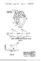
- FIG. 2indicates the catheter system of the present invention positioned in the heart
- FIG. 3illustrates a typical pressure curve for the right ventricle of a normally functioning heart
- FIG. 4is a circuit schematic of one embodiment of an electronic circuit which may be employed in the standby defibrillator of the present invention.
- FIG. 5is a graph of voltage versus time illustrating the operation of the sawtooth generator forming a part of the present invention.
- the present inventionwill be explained for use in accomplishing ventricular defibrillation. However, it should be understood that the present invention could be employed for performing cardioversions with respect to other arrhythmic conditions as described above.
- FIG. 1shows a single intravascular catheter electrode system 10 which comprises a pacing tip shown generally at 11, a distal electrode shown generally at 12, and a proximal electrode indicated generally at 13.
- the term "catheter” as used hereinis intended to mean an intravascular or transvenous lead either with or without a lumen.
- the electrode system 10is designed so that it is protected from the corrosive environment inside the human vascular system, and is sealed so as to be inert to body fluids. Electrical connection is made via a coil spring wire 14, which is completely molded in a silicone rubber, substantially cylindrical casing 15, and which associates with a hollow conductive cap 16 affixed to the extreme distal end of catheter system 10.
- Cap 16serves as the electrodes or pacing tip if it is desired to use the catheter system in a pacemaking mode.
- a coil springis used so that a stylet may be passed therethrough to facilitate placement of the catheter system into proper position.
- Cap 16may, for example, be made of solid platinum irridium.
- Distal electrode 12comprises a plurality of spaced, conductive metal rings 17, three being shown in the illustrated embodiment.
- Metal rings 17may, for example, be made of solid platinum irridium and fit snugly to prevent lateral movement around casing 15.
- a spacing 18is left between adjacent rings 17 in order to provide the electrode with the necessary flexibility for positioning in the vascular system without undue stress and strain.
- a plurality of ringsdefine electrode 12 to provide sufficient surface area and hence good electrical contact with the heart tissues when the catheter is implanted. All of the rings 17 are electrically connected together in series by a low impedance wire 19.
- Wire 19may, for example, be platinum tinsel wire or three serve copper tinsel wire. The wire should be sufficiently conductive to adequately deliver the voltage levels used in defibrillating.
- Proximal electrode 13comprises a plurality of spaced-apart conductive metal rings 20, with four being illustrated in the FIG. 1 embodiment.
- Metal rings 20may, for example, be made of solid platinum irridium and fit snugly about the molded silicone rubber casing 15.
- a spacing 21is left between adjacent rings 20 in order to provide the electrode with the necessary flexibility for positioning in the vascular system without undue stress and strain.
- a plurality of ringsdefine electrode 13 to provide sufficient surface and good electrical contact with the heart tissues when the catheter is implanted. All of the rings 20 are elecrically connected together is series by a low impedance wire 22.
- Wire 22may, for example, be platinum tinsel wire or three serve copper tinsel wire. The wire should be sufficiently conductive to adequately deliver the voltage levels used in defibrillating.
- Casing 15seals wires 14, 19 and 22 so as to make them inert from body fluids as well as electrically insulates them from one another.
- the embodiment showndepicts the distal electrode 12 as having three conductive rings 17 and the proximal electrode 13 as having four conductive rings 20, the number of rings of each electrode may be varied. Also the length of each of the rings 17 and 20, as well as the spacings 18 and 21 respectively between them, may vary. The important relationship is that catheter system 10 be sufficiently flexible to be easily positioned within the vascular system, and at the same time have sufficient surface area on each of the electrodes to provide good electrical contact with the heart when catheter system 10 is properly positioned to deliver energy sufficient to cardiovert the heart. In the specific embodiment shown, rings 17 and 20 are each 1/4 inch in length and spacings 18 and 21 are each 3/8 inch. the overall length of catheter system 10 may typically be approximately 60 to 70 cm.
- interelectrode distance, dAnother dimension of importance is the interelectrode distance, d, shown in FIG. 1 between the distal electrode ring 17 farthest from cap 16 and the closest proximal electrode ring 20 thereto.
- dthe interelectrode distance between the distal electrode ring 17 farthest from cap 16 and the closest proximal electrode ring 20 thereto.
- the required distancewill be slightly different from one patient to the next.
- a good average for ventricular cardioversionis between four and four and one-half inches for the interelectrode distance, d.
- the distance, dwould be somewhere between 21/2 and 4 inches for the preferred embodiment.
- a sensing probe 23may be carried by catheter system 10 if it is used as an element of an automatic cardioverter.
- the sensing probecomprises a main body portion 24 and, for example, a pressure sensitive bulb 26. Electrical connections to bulb 26 are made at junction box 28.
- the main body 24 of the sensing probeis in the shape of a flat ribbon, and the body of bulb 26 is spherical.
- FIG. 2shows one possible position of catheter electrode system 10 in a heart for effecting ventricular defibrillation.
- Catheter system 10is introduced through a peripheral vein, such as, for example, the right jugular vein, by means of surgery very similar to that involved in the implantation of a pacemaking catheter.
- a peripheral veinsuch as, for example, the right jugular vein
- One very effective positionhas been found to be where the distal electrode 12 is wedged in the apex of the right ventricle and proximal electrode 13 is immediately superior to the right atrium or just outside the cardiac silhouette in the vascular system.
- distal electrode ring 17 farthest from cap 16should not be too close to the tricuspid valve and the proper intro-electrode distance, d, should be provided so that proximal electrode 13 lies just outside the cardiac silhouette.
- cap 16 of pacing tip 11 and electrode 12are electrically isolated from one another. At this time, therefore, conventional pacemaking signals may be applied between cap 16 and electrode 12 by delivering the appropriate pacemaking signals to coil spring 14 and wire 19, respectively. Since the heart responds favorably to the pacemaking signals only if cap 16 of pacing tip 11 is properly positioned, this method is suitable for checking the position of catheter system 10. The proper location may, of course, be recognized by other methods such as, for example, fluoroscopy or pressure recordings. Once it is determined that catheter system 10 is properly located, it is secured in place and the pacemaking electronics, if unnecessary for the particular patient, are disconnected. The electronic circuit associated with the standby defibrillator of the present invention is then connected to electrodes 12 and 12 via wires 19 and 22, respectively.
- FIG. 3there is illustrated a right ventricular pressure curve for a normally functioning heart. Only pulses 30 and 32 are illustrated for ease of description, though such pulses repeat at the rate of approximately 60 to 70 per minute in a normally functioning heart.
- FIG. 3clearly shows that each pulse has a peak and that these peaks rise above a preset pressure indicated by the dotted line 38. This dotted line corresponds to the threshold between a healthy heart and one which is in need of cardioversion.
- probe 23which, as will be described immediately below, initiates the cardioversion of the heart.
- FIG. 4one embodiment of an electronic circuit which may be used with the standby defibrillator of the present invention will be described.
- the electronic circuitry of FIG. 4may conveniently be broken down into several component parts.
- the first partis a pressure transducer shown at 40, this pressure transducer being directly associated with the pressure sensing probe 23.
- the next stage of the electronicsis a combination of an amplifier and a sawtooth generator shown at block 42.
- the amplifieris adapted to amplify the signals received from pressure transducer 40.
- the sawtooth generatorcomprises a transistor and a capacitor connected between the collector electrode of the transistor and ground.
- the signal from the sawtooth generatoris then passed to an output amplifier shown at 44, which amplifier in turn feeds its output signal to the base of a transistor associated with the relay stage shown at 46.
- the relay 46is normally in its open state condition, but when it is closed, a DC signal is impressed upon a DC/DC converter stage 48.
- the DC/DC converter 48boosts the input voltage from approximately 15 volts to the necessary defibrillating voltage.
- the DC voltage signal from the converter 48is then fed to a storage capacitor 70 which is associated with a firing circuit, the entire combination shown at 50.
- the firing circuit 50triggers the discharge of the capacitor 70, the necessary defibrillating voltage signal is applied to the electrodes 12 and 13 illustrated in FIG. 1. Therefore, when the sensing probe 23 senses a malfunction in the heart, the capacitor, after a predetermined time delay, shocks the heart with the appropriate defibrillating voltage.
- the pressure transducer 40takes the form of a resistive bridge, one resistor of which is defined by the pressure sensor 26 on the tip of the probe 23. The remaining legs in the bridge are defined by resistors housed in the junction box 28 shown in FIG. 1.
- the pressure transducer 40is arranged so that the pressure sensed by element 26 is converted to an electrical signal, the amplitude of which is directly proportional to the sensed pressure.
- the output from the pressure transducer 40is fed to a conventional multistage amplifier shown in block 42 which amplifies the received pulses and which then feeds these amplified pulses to the sawtooth generator also in block 42.
- the trimming potentiometer 52is provided to balance the inputs to the associated amplifier.
- the sawtooth generatorif unaffected by the external environment, will have an output curve such as that shown at 54 in FIG. 5. However, if a signal is fed to the sawtooth generator, and if the signal is at least of a predetermined amplitude, then the output voltage of the generator on lead 56 will immediately drop to zero and then again begin to climb. Therefore, if the sawtooth generator receives repetitious pulses of at least the predetermined voltage, then its output will be similar to that shown in FIG. 5 by waveform 58.
- the amplified signal corresponding to a pulse in ventricular pressurewill cause the output of the sawtooth generator to drop to zero.
- the threshold signal reaching the sawtooth generatorcan be adjusted by adjusting the amplification factor of the signal amplifier shown in block 42.
- Amplifier 44has a threshold which is adjusted by potentiometer 62 so that the amplifier 44 actuates the relay 64 only after approximately 6 seconds of heart malfunction. If, then, the ventricular pressure falls lower than that value indicated by the dotted line 38, and so remains for the preset time interval, the amplified voltage reaching the generator will be insufficient to cause the generator output to drop to zero. Rather, the generator output will follow the curve shown at 54 in FIG. 5, and the threshold of amplifier 44 will be reached. Trimming potentiometer 60 is provided to balance the inputs to the associated output amplifier 44 from lead 56 and potentiometer 62.
- the output from the amplifier 44is fed to the relay circuit 46.
- the relay contacts shown generally at 64are initially set in the open-circuit condition, thereby isolating the 15 volt source from the DC/DC converter 48. Further, the relay 46 is set to close only after the current passing though coil 66 reaches a predetermined value. With reference to FIG. 5, the voltage output of the sawtooth generator must be at the level 68, the threshold of amplifier 44, before the current in the coil 66 is sufficient to switch the relay 64 into its closed-circuit state.
- the operation of the firing circuit 50is as follows: the voltage signal from the converter 48 is fed to the capacitor 70.
- the transistor 72becomes conductive, due to the now-conducting neon tube 74.
- the resistor chains and the tube 74are interconnected in such a manner that when the voltage across the capacitor 70 reaches the full voltage level from converter 48, then the tube 74 becomes conductive.
- the tube 74conducts, so too does transistor 72 and, therefore, SCR 76.
- the full defibrillating voltagepasses through electrodes 12 and 13 thus shocking the heart with a voltage sufficient to cause defibrillation.
- a time periodelapse between the detection of a heart malfunction and the delivery of the defibrillating shock to the heart.
- an approximately 6 second delayoccurs between the first detection of a malfunction and the closing of relay 64.
- there is an additional delayon the order of a few more seconds, which is brought about by the charge time of capacitor 70. That is, when the relay 64 closes, 6 seconds after the initial malfunction, the capacitor first begins to charge.
- the twenty secondsmay be enlarged or contracted as desired. And, as mentioned above, if at any time during the delay period the heart returns to normal, then the delay period automatically begins again.
Landscapes
- Health & Medical Sciences (AREA)
- Cardiology (AREA)
- Heart & Thoracic Surgery (AREA)
- Nuclear Medicine, Radiotherapy & Molecular Imaging (AREA)
- Engineering & Computer Science (AREA)
- Biomedical Technology (AREA)
- Radiology & Medical Imaging (AREA)
- Life Sciences & Earth Sciences (AREA)
- Animal Behavior & Ethology (AREA)
- General Health & Medical Sciences (AREA)
- Public Health (AREA)
- Veterinary Medicine (AREA)
- Vascular Medicine (AREA)
- Electrotherapy Devices (AREA)
Abstract
Description
This is a continuation-in-part of U.S. Pat. Application Ser. No. 124,326 filed Mar. 15, 1971, now abandoned.
During the past several decades, coronary heart disease has come to occupy the first position among the causes of death in the developed areas of the world. In the United States, for example, this disease is responsible for over one-half million deaths yearly. And of this number, more than half occur suddenly, outside the hospital, and therefore before the patient is able to obtain the necessary medical assistance. Although the precise cause of sudden death in coronary heart disease has not yet been entirely clarified, the available evidence permits the medical field to ascribe death in the majority of these cases to grave disturbances in cardiac electrical activity culminating in ventricular fibrillation.
The frustrating but related problem is the present inability to deal effectively with lethal and non-lethal arrhythmias outside of a hospital setting. Within the hospital environment, recent experience has clearly demonstrated that ventricular fibrillation and its frequent precursor, ventricular tachycardia, are reversible phenomena when prompt defibrillation of the heart is instituted. Under such circumstances, cardiac function can frequently be restored to normal without the patient suffering from residual disability. Unfortunately, however, the state of the art makes defibrillation very much dependent upon a highly specialized medical environment, thus limiting such treatment to elaborately equipped modern hospitals.
There is no question that a great need exists for a defibrillator which could be carried by those who are prone to having one of the many life threatening arrhythmias generally discussed above. Thus, in some patients having coronary heart disease, a fatal outcome from ventricular tachycardia or ventricular fibrillation could be avoided, even in the absence of immediate medical assistance. The first step, of course, is the detection of those prone to suffering from cardiac malfunctions leading to ventricular tachycardia or ventricular fibrillation.
While it is not possible to predict with unerring certainty which patients suffering from coronary heart disease will be the victims of sudden death, several high risk groups of patients can be recognized. For example, patients who have experienced myocardial infarction, even though they may be surviving in good health, run a substantial risk of dying suddenly, a risk several times greater than that associated with the general population. Further, if patients with myocardial infarction have a history of serious ventricular arrhythmias and/or of cardiac arrest, or if evidence of persistent myocardial irritability is present, it may logically be assumed that the risk of sudden death is increased substantially. Patients like those described above would greatly benefit from an automatic, standby or demand defibrillator.
Also, such an automatic defibrillator would be an asset to those hospitalized patients who have suffered myocardial infarction both in the coronary care unit and those who have been discharged from the well-equipped coronary care unit. Under such circumstances, the defibrillator could be utilized temporarily for the remainder of the expected hospital stay; or the automatic defibrillator could be permanently implanted for use both in the hospital and after discharge.
Another recognizable class of patients particularly in need of an automatic defibrillator is the class composed of those who have not shown prior histories of myocardial infarction but who show severe symptoms of coronary heart disease, such as ventricular arrhythmias resistant to medical treatment or angina pectoris.
From the brief discussion above, there should be little doubt that the possible applications for an automatic defibrillator are numerous. Such automatic standby defibrillators have been developed and are described in U.S. Pat. No. Re. 27,757 entitled STANDBY DEFIBRILLATOR AND METHOD OF OPERATION and U.S. Pat. No. Re. 27,652 entitled ELECTRONIC STANDBY DEFIBRILLATOR.
The automatic standby defibrillators described in the above-identified patents employ a sensing probe carrying one electrode which is positioned in the right ventricle of the heart. A second electrode, separate from and unconnected to the sensing probe, is generally a flat plate either placed on the outer surface of the chest, sutured under the skin of the anterior chest wall or applied directly to the ventricular myocardium. As a result, these systems require much more surgery and, depending on the position of the second electrode, may ultimately be only partially implanted. In addition, such systems require a capacitor of sufficient size and capacity to store approximately several hundreds of watt-seconds, which is the necessary energy required in those systems to produce defibrillation. Therefore, it is evident that an automatic standby or even a manually initiated defibrillating system which requires a much lower energy level, thereby being much smaller and compact in size and which may be totally and completely implanted within the patient, would be highly desirable and would represent a great improvement.
Another drawback of the prior art relates to the possibility of developing ventricular fibrillation in the course of correcting, for example, atrial fibrillation. In the prior art, the heart is often brought out of artial fibrillation by delivering an electrical shock across the chest by means of precordial electrodes, or paddles. With such an arrangement, it is necessary to develop a large electrical potential across the paddles, but impossible to centralize the potential across the atria. Accordingly, it is essential to very carefully time the pulses delivered to bring a malfunctioning heart out of atrial fibrillation, or the large shock across the ventricles may induce ventricular fibrillation. This is yet another indication of the need for a low-energy intravascular electrode system capable of accurately delivering electrical pulses to localized areas of the heart.
Two other disadvantages of the prior art high-energy cardioverting systems, and the need for improvement, should be noted. First, because of the extreme pain which could be experienced by a patient undergoing high-energy cardioversion, it is the practice to administer a general anesthetic before an attempted cardioversion. With a low-energy intravascular electrode system, the use of a general anesthetic can be avoided.
Secondly, the application of high-energy electrical shocks across the chest of a patient carries with it substantial risk of cardiac damage. Again, by way of a low-energy intravascular electrode system capable of localizing defibrillating electrical shocks, the potential risk of injuring the myocardium is considerably decreased.
In this regard, efforts have been made to experiment with defibrillators other than that described above. For one, see Hopps et al., "Electrical Treatment of Cardiac Arrest: A Cardiac Stimulator-Defibrillator," Surgery, Vol. 36, No. 4 (Oct. 1954), at pages 833-849. There, the researchers attempted to bring dogs out of ventricular fibrillation by using an intracardiac electrode carrying two very closely spaced electrodes. The authors concluded that shocks applied through an intracardiac catheter were not effective in cardiac defibrillation. A second example can be seen in recently issued U.S. Pat. No. 3,738,370. There, a single catheter carries a pair of electrodes spaced together so closely as to allow placement of both electrodes in the atrium. Though the patentee alleges effective cardioversion, the energy levels are higher than are actually necessary. The electrode spacing and location are seen to be the reasons. Therefore, to date, the medical field is without a simple, low-energy cardioverting device using a single intravascular electrode catheter capable of treating a wide range of atrial and ventricular arrythmias.
The present invention relates to just such a cardioverting device. As used herein, a cardioverter is an electronic system which, after detecting one of the above-noted lethal or non-lethal arrhythmias, reestablishes normal heart function in the heart of the user. "Cardioverting" or "cardioversion" as used herein is intended to encompass the correction of a number of arrhythmic heart conditions, both lethal and non-lethal. Those arrhythmic heart conditions include atrial tachycardia, atrial flutter, atrial fibrillation, junctional rhythms, ventricular tachycardia, ventricular flutter, and ventricular fibrillation, and any other non-pacemaking related arrhythmic condition which may be corrected by applying electrical shocks to the heart. Obviously then, "defibrillation" is included in the term cardioversion as a method of applying electrical shocks to the heart to defibrillate fibrillating atria or fibrillating ventricles.
The system of the present invention may be installed in patients particularly prone to develop ventricular tachycardia and/or ventricular fibrillation, or other types of tachyarrhythmias which may be corrected by cardioverting, either on a temporary or a permanent basis. And, because of extremely small and compact size, the system including both electrodes may be totally and completely implanted under the skin of the patient, or alternatively, may be carried externally, save for the sensing probe carrying the two electrodes.
More particularly, the present invention relates to a device for reliably sensing the differences between a properly functioning heart and one which has suddenly developed an arrhythmia correctable by cardioverting, and for then delivering a cardioverting shock to the arrhythmic heart. The device is adapted to continue delivering intermittent shocks to the heart in the event that the heart fails to return to its normal behavior pattern, and has the ability of automatically regaining sensing control over a functional heart thereby ensuring that further shocks are inhibited after successful cardioversion has taken place.
The standby defibrillator of the present invention has as its basic element, a capacitor capable of storing electrical energy in an amount sufficient to cardiovert a malfunctioning human heart. Upon discharge of this capacitor, a shock is delivered to the heart through the two stimulating electrodes. A sensing probe carries both electrodes, the whole unit forming a single intravascular catheter electrode system. One electrode forms the distal tip of the intracardiac catheter and is positioned within the right ventricle (when dealing with a ventricular arrhythmia) while the second stimulating electrode is spaced from the first electrode and is positioned either within the heart or in the vascular system outside the heart.
The capacitor is associated with a sensing circuit connected to the proximal end of the intracardiac catheter and is adapted to respond to a signal recorded at the distal end of the catheter. The signal sensed by the catheter must, of course, be inherently related to some distinctive characteristic of ventricular tachycardia or ventricular fibrillation; and in a specific embodiment of the present invention, the pressure in the right ventricle is sensed. When this pressure falls below a given value, on the order of 5 to 15 mm hg, the heart is malfunctioning and, therefore, the capacitor is discharged into the heart.
Between the sensing circuit and the capacitor, means are provided for delaying the repetition of depolarizing discharges for a preset period of time (on the order of 10 to 30 seconds). This delay is essential to give the heart the opportunity to be converter spontaneously to a normal cardiac rhythm, and also to ensure that the abnormal heart conditions are, in face, critical. Only in the absence of a successful conversion is a subsequent shock delivered to the heart. In a particular embodiment of the present invention, the time delay is brought about with the aid of a sawtooth generator, a relay and the charge time of the storage capacitor.
The above discussion, for the most part, has been directed to ventricular arrhythmias. It should be remembered, however, that the present invention is also well suited to treat arrhythmias of the atria. When being used in such a mode of operation, one electrode of the catheter is positioned in the right atrium while the other electrode resets outside the heart.
Accordingly, an aspect of the present invention is to provide either a manual or an automatic standby cardioverting device having a single intravascular catheter electrode system.
Another feature of the present invention is the provision of either a manual or an automatic standby cardioverting device capable of defibrillating a malfunctioning heart extremely rapidly and at relatively low energy levels. This device is extremely compact and includes an electrode system which is totally and completely implantable in the body of a patient. The unit lies dormant during normal heart activity but applies a shock to the heart when the heart functions become abnormal. If the unit is automatic, it reliably senses the difference between a normally functioning heat and one which has suddenly developed abnormal function, and then automatically delivers a cardioverting shock to the heart. Further, the unit is capable of delivering multiple shocks in the event that the heart is not successfully cardioverted by the initial shock; and is designed to automatically regain sensing control over a functioning heart, thereby inhibiting further shocks after successful cardioversion. Still another feature of the present invention is that it may sense conditions requiring either cardioversion or pacing.
The particular design of the intravenous catheter is an important aspect of the present invention. First, it is important that the catheter be flexible. Otherwise, the catheter could not safely be inserted and positioned in the heart. Second, it is important that the electrodes on the catheter have a sufficient contact surface so as to effectively discharge the stored energy through the heart. Thirdly, the electrode placement in the heart and, hence, the spacing between the distal and proximal electrodes on the catheter, are important to the effectiveness of the device. In the preferred embodiment of the invention, the intravascular catheter includes at least two spaced electrodes for discharging energy into the heart, with the electrode spacing being such that when the distal electrode is located in the heart cavity undergoing the arrythmia to be cardioverted, the proximal electrode lies outside the heart.
Based upon the foregoing preferred criteria, and in light of the well-known average heart sizes, the electrode spacing can be determined. For example, in the average adult, the heart measures about 121/2 cm. from the base to the apex. On the other hand, the length of the right ventricular inflow tract, that is, the internal spacing between the tricuspid annulus and the apex, is approximately 71/2 cm. Thus, taking into consideration the average thickness of the ventricles, the spacing between the base of the right atrium and the superior vena cava is approximately 31/2 cm. See, for example, S. E. Gould, Pathology of the Heart, 2d. Ed., Charles C. Thomas, publisher, p. 95; and S. A. O. Eckner, et al., "Dimensions of Normal Human Hearts," Archives of Pathology, vol. 88 (1969), pp. 497-507.
While it is preferable that an electrode be tailored to the user, based upon his precise heart measurements, useful ranges of electrode spacings can be set out for commercial production.
For ventricular cardioversion, the most adjacent distal and proximal electrodes are spaced at least two and one-half to three inches apart. As a practical range, the electrodes would be spaced apart somewhere between two and one-half and six inches apart. More preferably, the spacing would be between three and five inches, and for commercial exploitation, would be between 4 and 41/2 inches. For atrial cardioversion, on the other hand, the electrodes would be spaced at least 21/2 to 3 inches apart, with the maximum electrode spacing again being somewhere between 21/2 and 6 inches, and in the commercial embodiment, would be spaced apart somewhere from between 21/2 and 4 inches.
These and other aspects of the invention, as well as many of the attendant advantages thereof, will become more readily apparent when reference is made to the following description taken in conjunction with the accompanying drawings.
FIG. 1 is a side view of the combination sensing probe and electrode structures defining the single intravascular catheter electrode system which forms a part of the present invention;
FIG. 2 indicates the catheter system of the present invention positioned in the heart;
FIG. 3 illustrates a typical pressure curve for the right ventricle of a normally functioning heart;
FIG. 4 is a circuit schematic of one embodiment of an electronic circuit which may be employed in the standby defibrillator of the present invention; and
FIG. 5 is a graph of voltage versus time illustrating the operation of the sawtooth generator forming a part of the present invention.
For purposes of description, the present invention will be explained for use in accomplishing ventricular defibrillation. However, it should be understood that the present invention could be employed for performing cardioversions with respect to other arrhythmic conditions as described above.
FIG. 1 shows a single intravascularcatheter electrode system 10 which comprises a pacing tip shown generally at 11, a distal electrode shown generally at 12, and a proximal electrode indicated generally at 13. The term "catheter" as used herein is intended to mean an intravascular or transvenous lead either with or without a lumen. Theelectrode system 10 is designed so that it is protected from the corrosive environment inside the human vascular system, and is sealed so as to be inert to body fluids. Electrical connection is made via acoil spring wire 14, which is completely molded in a silicone rubber, substantiallycylindrical casing 15, and which associates with a hollowconductive cap 16 affixed to the extreme distal end ofcatheter system 10.Cap 16 serves as the electrodes or pacing tip if it is desired to use the catheter system in a pacemaking mode. A coil spring is used so that a stylet may be passed therethrough to facilitate placement of the catheter system into proper position.Cap 16 may, for example, be made of solid platinum irridium.
Although the embodiment shown depicts thedistal electrode 12 as having threeconductive rings 17 and theproximal electrode 13 as having fourconductive rings 20, the number of rings of each electrode may be varied. Also the length of each of therings spacings 18 and 21 respectively between them, may vary. The important relationship is thatcatheter system 10 be sufficiently flexible to be easily positioned within the vascular system, and at the same time have sufficient surface area on each of the electrodes to provide good electrical contact with the heart whencatheter system 10 is properly positioned to deliver energy sufficient to cardiovert the heart. In the specific embodiment shown, rings 17 and 20 are each 1/4 inch in length andspacings 18 and 21 are each 3/8 inch. the overall length ofcatheter system 10 may typically be approximately 60 to 70 cm.
Another dimension of importance is the interelectrode distance, d, shown in FIG. 1 between thedistal electrode ring 17 farthest fromcap 16 and the closestproximal electrode ring 20 thereto. Of course, the required distance will be slightly different from one patient to the next. However, a good average for ventricular cardioversion is between four and four and one-half inches for the interelectrode distance, d. For atrial cardioversion, the distance, d, would be somewhere between 21/2 and 4 inches for the preferred embodiment.
A sensing probe 23 may be carried bycatheter system 10 if it is used as an element of an automatic cardioverter. The sensing probe comprises amain body portion 24 and, for example, a pressuresensitive bulb 26. Electrical connections tobulb 26 are made atjunction box 28. Themain body 24 of the sensing probe is in the shape of a flat ribbon, and the body ofbulb 26 is spherical.
FIG. 2 shows one possible position ofcatheter electrode system 10 in a heart for effecting ventricular defibrillation.Catheter system 10 is introduced through a peripheral vein, such as, for example, the right jugular vein, by means of surgery very similar to that involved in the implantation of a pacemaking catheter. One very effective position has been found to be where thedistal electrode 12 is wedged in the apex of the right ventricle andproximal electrode 13 is immediately superior to the right atrium or just outside the cardiac silhouette in the vascular system. In this positiondistal electrode ring 17 farthest fromcap 16 should not be too close to the tricuspid valve and the proper intro-electrode distance, d, should be provided so thatproximal electrode 13 lies just outside the cardiac silhouette.
When thecatheter system 10 is being inserted in proper position as shown in FIG. 2, cap 16 of pacing tip 11 andelectrode 12 are electrically isolated from one another. At this time, therefore, conventional pacemaking signals may be applied betweencap 16 andelectrode 12 by delivering the appropriate pacemaking signals tocoil spring 14 andwire 19, respectively. Since the heart responds favorably to the pacemaking signals only ifcap 16 of pacing tip 11 is properly positioned, this method is suitable for checking the position ofcatheter system 10. The proper location may, of course, be recognized by other methods such as, for example, fluoroscopy or pressure recordings. Once it is determined thatcatheter system 10 is properly located, it is secured in place and the pacemaking electronics, if unnecessary for the particular patient, are disconnected. The electronic circuit associated with the standby defibrillator of the present invention is then connected toelectrodes wires 19 and 22, respectively.
With reference now to FIG. 3, there is illustrated a right ventricular pressure curve for a normally functioning heart.Only pulses line 38. This dotted line corresponds to the threshold between a healthy heart and one which is in need of cardioversion. When the height of thepeaks line 38, the malfunction is sensed by probe 23 which, as will be described immediately below, initiates the cardioversion of the heart.
With reference then to FIG. 4, one embodiment of an electronic circuit which may be used with the standby defibrillator of the present invention will be described. The electronic circuitry of FIG. 4 may conveniently be broken down into several component parts. The first part is a pressure transducer shown at 40, this pressure transducer being directly associated with the pressure sensing probe 23. The next stage of the electronics is a combination of an amplifier and a sawtooth generator shown atblock 42. The amplifier is adapted to amplify the signals received frompressure transducer 40. The sawtooth generator comprises a transistor and a capacitor connected between the collector electrode of the transistor and ground. The signal from the sawtooth generator is then passed to an output amplifier shown at 44, which amplifier in turn feeds its output signal to the base of a transistor associated with the relay stage shown at 46. Therelay 46 is normally in its open state condition, but when it is closed, a DC signal is impressed upon a DC/DC converter stage 48. The DC/DC converter 48 boosts the input voltage from approximately 15 volts to the necessary defibrillating voltage. The DC voltage signal from theconverter 48 is then fed to astorage capacitor 70 which is associated with a firing circuit, the entire combination shown at 50. When thefiring circuit 50 triggers the discharge of thecapacitor 70, the necessary defibrillating voltage signal is applied to theelectrodes
Still referring to FIG. 4, but in greater detail, the circuitry associated with the present invention functions as follows. Thepressure transducer 40 takes the form of a resistive bridge, one resistor of which is defined by thepressure sensor 26 on the tip of the probe 23. The remaining legs in the bridge are defined by resistors housed in thejunction box 28 shown in FIG. 1. Thepressure transducer 40 is arranged so that the pressure sensed byelement 26 is converted to an electrical signal, the amplitude of which is directly proportional to the sensed pressure. The output from thepressure transducer 40 is fed to a conventional multistage amplifier shown inblock 42 which amplifies the received pulses and which then feeds these amplified pulses to the sawtooth generator also inblock 42. The trimmingpotentiometer 52 is provided to balance the inputs to the associated amplifier.
With reference now to FIGS. 3 through 5, the operation of the sawtooth generator will be described. the sawtooth generator, if unaffected by the external environment, will have an output curve such as that shown at 54 in FIG. 5. However, if a signal is fed to the sawtooth generator, and if the signal is at least of a predetermined amplitude, then the output voltage of the generator onlead 56 will immediately drop to zero and then again begin to climb. Therefore, if the sawtooth generator receives repetitious pulses of at least the predetermined voltage, then its output will be similar to that shown in FIG. 5 bywaveform 58.
If the heart functions sensed by thepressure transducer 40 are normal, following the curve shown in FIG. 3, then the amplified signal corresponding to a pulse in ventricular pressure will cause the output of the sawtooth generator to drop to zero. The threshold signal reaching the sawtooth generator can be adjusted by adjusting the amplification factor of the signal amplifier shown inblock 42.Amplifier 44 has a threshold which is adjusted bypotentiometer 62 so that theamplifier 44 actuates the relay 64 only after approximately 6 seconds of heart malfunction. If, then, the ventricular pressure falls lower than that value indicated by the dottedline 38, and so remains for the preset time interval, the amplified voltage reaching the generator will be insufficient to cause the generator output to drop to zero. Rather, the generator output will follow the curve shown at 54 in FIG. 5, and the threshold ofamplifier 44 will be reached. Trimming potentiometer 60 is provided to balance the inputs to the associatedoutput amplifier 44 fromlead 56 andpotentiometer 62.
The output from theamplifier 44 is fed to therelay circuit 46. The relay contacts shown generally at 64 are initially set in the open-circuit condition, thereby isolating the 15 volt source from the DC/DC converter 48. Further, therelay 46 is set to close only after the current passing though coil 66 reaches a predetermined value. With reference to FIG. 5, the voltage output of the sawtooth generator must be at thelevel 68, the threshold ofamplifier 44, before the current in the coil 66 is sufficient to switch the relay 64 into its closed-circuit state.
When the relay 64 closes, then the 15 volt source is connected directly to the DC/DC converter 48. From FIGS. 3 through 5, it can be seen that approximately six seconds must elapse, with the heart continuously malfunctioning, before the relay 64 switches from its open-circuit mode to its closed-circuit mode. This will be apparent when one realizes that each "tooth" of thecurve 58 corresponds to one peak of the right ventricular pressure response and, as noted above, the peaks of the pressure curve repeat at approximately 60 to 70 per minute. Therefore, absence of a coordinated ECG-ventricular pressure peak must exist for approximately six seconds before input voltage is fed to the DC/DC converter 48. If the heart returns to its normal function at any time during that 6 seconds, then the sawtooth generator output response would drop to zero and the six second cycle would begin again.
With the relay 64 closed and a 15 volt or other DC signal appropriate from implantable battery sources being impressed upon theconverter 48, an output of sufficient voltage to produce defibrillation appears at the output terminals of theconverter 48 whencapacitor 70 is fully charged. Simultaneously, this voltage signal is fed to a resistive chain and finally to the base oftransistor 72 via aneon tube 74. A silicon controlled rectifier (SCR) 76 is triggered on whentransistor 72 becomes conductive.
The operation of thefiring circuit 50 is as follows: the voltage signal from theconverter 48 is fed to thecapacitor 70. When thecapacitor 70 is fully charged, thetransistor 72 becomes conductive, due to the now-conductingneon tube 74. The resistor chains and thetube 74 are interconnected in such a manner that when the voltage across thecapacitor 70 reaches the full voltage level fromconverter 48, then thetube 74 becomes conductive. When thetube 74 conducts, so too doestransistor 72 and, therefore, SCR 76. Then, the full defibrillating voltage passes throughelectrodes
As noted above, it is important that a time period elapse between the detection of a heart malfunction and the delivery of the defibrillating shock to the heart. As also noted above, an approximately 6 second delay occurs between the first detection of a malfunction and the closing of relay 64. Then, there is an additional delay, on the order of a few more seconds, which is brought about by the charge time ofcapacitor 70. That is, when the relay 64 closes, 6 seconds after the initial malfunction, the capacitor first begins to charge. Preferably, less than 20 seconds elapse between the initial sensing of heart fibrillation and the discharge of the capacitor into the heart. Naturally by varying the rise time of the sawtooth generator and the charge time of the capacitor, the twenty seconds may be enlarged or contracted as desired. And, as mentioned above, if at any time during the delay period the heart returns to normal, then the delay period automatically begins again.
In recent animal experiments using dogs in which fibrillation was induced by an alternating current electrical signal, defibrillation was achieved successfully in less than 3 watt-seconds at voltages as low as a few hundred volts. Even more recently, success in atrial cardioversion was achieved at an energy level of a mere 0.1 watt-seconds. However, it is possible that effective results at lower energies may be achieved by appropriate selection of the system's parameters.
Above, a specific embodiment of the present invention has been described. It should be understood, however, that this description is given for illustrative purposes only and that many alterations and modifications may be practiced without departing from the spirit and scope of the invention. Just as a few examples, it should be understood that while in the specific embodiment of the present invention, the pressure in the right ventricle is sensed as an indication of heart malfunction, other sensing arrangements may be practiced. Further, a single SCR is used as a triggering device. It is possible to substitute this device for a plurality of SCR units or, alternatively, with a vacuum relay. Still further, while the above description shows a single storage capacitor, a series of capacitors could be employed. It is, therefore, the intent that the present invention not be limited to the above but be limited only as defined in the appended claims.
Claims (42)
1. A method for cardioverting a malfunctioning heart with a single intravascular catheter carrying first and second spaced electrodes for delivering to the heart electrical energy to cardiovert the same, the method comprising the steps of: positioning the single intravascular catheter into association with the heart with said first electrode located within the heart chamber to be cardioverted and said second electrode located outside said heart chamber; sensing heart activityl; and delivering cardioverting electrical energy to the heart across said first and second electrodes when a manfunction susceptible to conversion by electrical shock is sensed.
2. The method of claim 1, wherein said first and second electrodes are spaced apart a distance of at least about 21/2 inches.
3. The method of claim 2, wherein said first and second electrodes are spaced apart a distance of between about 3 and 5 inches.
4. The method of claim 3, wherein said first and second electrodes are spaced apart a distance of between about 4 and 41/2 inches.
5. The method of claim 2, wherein said first and second electrodes are spaced apart a distance of between about 21/2 and 4 inches.
6. The method of claim 1, wherein the cardioverting electrical energy is of at least approximately 0.1 watt-seconds.
7. The method of claim 1, wherein said single intravascular catheter is flexible for safe passage through the venous system, and wherein said electrodes are ring shaped.
8. The method of claim 1, and further comprising the step of: delaying the delivery of energy to the heart for a predetermined time after sensing a malfunction.
9. The method of claim 1, and further comprising the step of: reinitiating the delivery of electrical energy if the heart should fail to be cardioverted after a delivery of energy.
10. The method of claim 1, wherein said second electrode is located outside the heart, within the vascular system.
11. In a system for cardioverting a malfunctioning heart, comprising storage means for storing electrical energy, sensing means for sensing heart malfunction susceptible to conversion by electrical shock, electrode means for electrically connecting the storage means to the heart, and means for initiating the discharge of the electrical energy stored by said storage means across said electrode means and into the heart upon sensing a malfunction: a single intravascular cardioverting catheter carrying said electrode means in the form of first and second electrodes for contacting the tissues of the heart so as to cardiovert the same upon discharge of said storage means, said first and second electrodes being spaced apart a distance of at least about two and one-half inches; and connecting means for connecting said first and second electrodes across said storage means.
12. The catheter of claim 11, wherein said first electrode comprises at least two conductive surfaces spaced apart from one another; wherein said second electrode is spaced apart from said first electrode by at least a distance greater than the spacing between each of said first electrode conductive surfaces; wherein said second electrode comprises at least two conductive surfaces spaced apart from one another; and further comprising: first connecting means for electrically connecting all of said conductive surfaces of said first electrode in series and adapted to be electrically connected to a first side of said storage means; and second connecting means for electrically connecting all of said conductive surfaces of said second electrode in series and adapted to be electrically connected to a second side of said storage means different in potential from said first side.
13. The catheter of claim 12, and further comprising: sealing means for providing electrical insulation and for maintaining the spacing between said conductive surfaces of said first electrode, between said first and second electrode and between said conductive surfaces of said second electrode and providing electrical insulation around and between said first and second connecting means.
14. The catheter of claim 12, wherein said conductive surfaces of said first and second electrodes are rings.
15. The catheter of claim 11, wherein the closest spacing between said first and second electrodes is between 3 and 5 inches.
16. The catheter of claim 15, wherein the closest spacing between said first and second electrodes is between 4 and 41/2 inches.
17. The catheter of claim 11, wherein the closest spacing between said first and second electrodes is between 21/2 and 4 inches.
18. The catheter of claim 11, wherein said catheter is of a flexible material to accommodate safe application through the vascular system.
19. The catheter of claim 11, wherein said system for cardioverting a malfunctioning heart further comprises conventional pacemaking electronics; and further comprising connection means for associating with said conventional pacemaking electronics.
20. The catheter of claim 11, wherein said sensing means comprises a pressure sensitive bulb located near one end of said catheter for sensing blood pressure.
21. The catheter of claim 11, and further comprising: means for sealing said connecting means so as to be inert to body fluids.
22. The catheter of claim 11, wherein said first electrode is adapted to be wedged into the apex of the right ventricle and said second electrode is adapted to be positioned immediately superior to the right atrium just outside the heart in the vascular system.
23. The catheter of claim 11, wherein said system for cardioverting a malfunctioning heart further comprises a conventional heart pacer; and further comprising: a pacing tip carried by said catheter at the very end thereof; and means for connecting said tip to said heart pacer; whereby said catheter is adapted to function both in a cardioverting mode and a pacemaking mode.
24. A system for cardioverting a malfunctioning heart, the system comprising: storage means for storing electrical energy; a single intravascular cardioverting catheter carrying spaced first and second electrode means connected across said storage means for connecting the storage means directly to the heart and contacting the tissues of the heart for cardioverting the heart upon discharge of said storage means, said first and second electrode means being spaced apart a distance of at least 21/2 inches; and means for switching said storage means into a discharge state, whereupon the stored energy is released and applied directly to the heart across said first and second electrode means.
25. The system as recited in claim 24, wherein one of said electrode means is adapted to be positioned within the heart cavity to be cardioverted, and the other of said electrode means is adapted to be positioned outside the heart.
26. The system as set forth in claim 24, and further comprising conventional pacemaking electronics for developing electrical pacing impulses; and means for connecting said pacemaking electronics to said single intravascular catheter.
27. The system as set forth in claim 24, wherein: said first electrode means carried by said catheter is near one end thereof and is adapted to be positioned within the heart; and said second electrode means carried by said catheter is adapted to be positioned outside the heart within the vascular system when said catheter is located in operative position.
28. The system as set forth in claim 24, wherein: said first electrode means carried by said catheter is located near one end of said catheter and comprises a plurality of conductive surfaces spaced apart from one another; said second electrode means carried by said catheter is spaced from said first electrode means by a distance greater than the spacings between each of said first electrode conductive surfaces, and comprises a plurality of conductive surfaces spaced apart from one another; and further comprising connector means for electrically connecting in series all of said conductive surfaces of said first electrode means; connector means for electrically connecting in series all of said conductive surfaces of said second electrode means; means for attaching the respective connector means across said storage means; and means for maintaining the spacing between said conductive surfaces of said first electrode means, between said first and second electrode means, and between said conductive surfaces of said second electrode means and for providing electrical insulation around and between the respective connector means.
29. A system for automatically cardioverting a malfunctioning heart, the system comprising: storage means for storing electrical energy; a single intravascular cardioverting catheter carrying sensing means for continually sensing the function of a heart, and at least two spaced electrodes for connecting the storage means directly to the heart and for contacting the tissues of the heart so as to cardiovert the heart upon discharge of said storage means, said spaced electrodes being separated by a distance of at least approximately 21/2 inches; discriminator means electrically in circuit with said sensing means and electrodes for discriminating between normal heart function and an arrhythmia correctable by cardioversion; and means for automatically switching said storage means into a discharge state, in response to a sensed arrhythmia correctable by cardioversion, whereupon the stored energy is applied directly to the heart through said electrodes to cardiovert the malfunctioning heart.
30. The system as set forth in claim 29, and further comprising: delay means for ensuring that a time delay exists between the sensing of the initial heart malfunction and the discharge of said storage means into the heart.
31. The system as set forth in claim 29, wherein said sensing means and at least one of said electrodes are adapted to be positioned within the heart.
32. The system as set forth in claim 29, wherein said switching means further comprises means for reinitiating the heart-shocking cycle if the heart should fail to be cardioverted after being shocked.
33. The system as set forth in claim 29, wherein said switching means inhibits the discharge of said storage means under conditions of normal heart activity.
34. The system as set forth in claim 29 wherein said catheter carries one of said electrodes near one end thereof and adapted to be positioned within the heart, and the other of said electrodes spaced from the first and adapted to be positioned outside the heart within the vascular system when said catheter is located in operative position.
35. The system as set forth in claim 29, wherein said single intravascular catheter comprises: a pressure sensitive bulb included in said sensing means and located near one end of said catheter for sensing blood pressure; the first of said electrodes carried by said catheter adjacent said bulb, said first electrode comprising a plurality of conductive surfaces, spaced apart from one another; the second of said electrodes spaced from said first electrode a distance greater than the spacings between each of said first electrode conductive surfaces, said second electrode comprising a plurality of conductive surfaces, spaced apart from one another; first means for electrically connecting all of said surfaces of said first electrode in series, said first means being adapted to be electrically connected to said storage means; second means for electrically connecting all of said surfaces of said second electrode in series, said second means being adapted to be electrically connected to said storage means; and means for maintaining the spacing between said conductive surfaces of said first electrode, between said first and second electrodes, and between said conductive surfaces of said second electrode and for providing electrical insulation around and between said first and second means.
36. A system for cardioverting a malfunctioning heart, the system comprising: an energy source for developing cardioverting electrical energy; storage means connected to said energy source for storing said electrical energy; a single intravascular cardioverting catheter carrying first and second spaced electrodes for connecting the storage means directly to the heart and contacting the tissues of the heart to cardiovert the same upon discharge of said storage means, said first electrode being fixed on said catheter at a first location and connected to one terminal of said storage means, said second electrode being electrically isolated from said first electrode, fixed on said catheter at a second location and connected to an opposite terminal of said storage means, said first electrode adapted to be positioned within the heart and said second electrode adapted to be positioned outside the heart; and means for switching said storage means into a discharge state, whereby the stored energy is released from said storage means and applied directly to the heart through said first and second electrodes to cardiovert the malfunctioning heart.
37. A system for automatically cardioverting a malfunctioning heart, the system comprising: an energy source for developing cardioverting electrical energy; storage means connected to said energy source for storing said electrical energy; a single intravascular cardioverting catheter carrying sensing means and at least first and second spaced electrodes for continually sensing the function of a heart, for connecting the storage means directly to the heart, and for contacting the tissues of the heart to cardiovert the same upon discharge of said storage means, said first of said electrodes being fixed on said catheter at a first location and connected to one terminal of said storage means, said second of said electrodes being electrically isolated from said first, fixed on said catheter at a second location and connected to an opposite terminal of said storage means, said first electrode adapted to be positioned within the heart and said second electrode adapted to be positioned outside the heart; discriminator means electrically in circuit with said sensing means and electrodes for receiving information from said sensing means indicative of heart function, and for discriminating between normal heart function and an arrhythmia correctable by cardioversion; and means for automatically switching said storage means into a discharge state, in response to a sensed arrhythmia correctable by cardioversion, whereupon the stored energy is applied directly to the heart through said electrodes to cardiovert the malfunctioning heart.
38. For use in a system for cardioverting a malfunctioning heart, an energy source for developing cardioverting electrical energy, a storage means connected to the energy source for storing the electrical energy until needed, first and second spaced electrodes connected across the storage means, and means for switching the storage means into a discharge state whereby the stored energy is released and applied directly to the heart through the first and second spaced electrodes to cardiovert the malfunctioning heart, the improvement comprising: a single intravascular cardioverting catheter carrying the first and second spaced electrodes for connecting the storage means directly to the heart and contacting the tissues of the heart to cardiovert the same upon discharge of said storage means, said first electrode being fixed on the catheter at a first location and connected to one terminal of said storage means, and said second electrode being fixed on the catheter at a second location spaced from the first and connected to an opposite terminal of said storage means, one of said electrodes adapted to be positioned within the heart chamber to be cardioverted and the other of said electrodes adapted to be positioned outside said heart chamber.
39. The catheter of claim 38, wherein said first and second electrodes are spaced apart a distance of at least 21/2 inches.
40. A system for cardioverting a malfunctioning heart, the system comprising: storage means for storing electrical energy of at least approximately 0.1 watt-seconds; sensing means for sensing heart malfunction susceptible to cardioversion by electrical shock; a single intravascular cardioverting catheter carrying first and second electrodes spaced apart a distance of at least about 21/2 inches; means for connecting said first and second electrodes across said storage means; and switching means for responding to heart malfunctions sensed by said sensing means by discharging the energy stored by said storage means across said first and second electrodes and into said malfunctioning heart.
41. The system of claim 40, wherein said first and second electrodes are spaced apart on said cardioverting catheter by an intermediate catheter body of flexible material.
42. The system of claim 40, wherein said first and second electrodes are elongated and are flexible along their respective lengths.
Priority Applications (1)
| Application Number | Priority Date | Filing Date | Title |
|---|---|---|---|
| US05/398,793US3942536A (en) | 1971-03-15 | 1973-09-19 | Cardioverting device having single intravascular catheter electrode system and method for its use |
Applications Claiming Priority (2)
| Application Number | Priority Date | Filing Date | Title |
|---|---|---|---|
| US12432671A | 1971-03-15 | 1971-03-15 | |
| US05/398,793US3942536A (en) | 1971-03-15 | 1973-09-19 | Cardioverting device having single intravascular catheter electrode system and method for its use |
Related Parent Applications (1)
| Application Number | Title | Priority Date | Filing Date |
|---|---|---|---|
| US12432671AContinuation-In-Part | 1971-03-15 | 1971-03-15 |
Publications (2)
| Publication Number | Publication Date |
|---|---|
| US3942536Atrue US3942536A (en) | 1976-03-09 |
| US3942536B1 US3942536B1 (en) | 1987-03-24 |
Family
ID=26822441
Family Applications (1)
| Application Number | Title | Priority Date | Filing Date |
|---|---|---|---|
| US05/398,793Expired - LifetimeUS3942536A (en) | 1971-03-15 | 1973-09-19 | Cardioverting device having single intravascular catheter electrode system and method for its use |
Country Status (1)
| Country | Link |
|---|---|
| US (1) | US3942536A (en) |
Cited By (198)
| Publication number | Priority date | Publication date | Assignee | Title |
|---|---|---|---|---|
| US4088140A (en)* | 1976-06-18 | 1978-05-09 | Medtronic, Inc. | Demand anti-arrhythmia pacemaker |
| US4161952A (en)* | 1977-11-01 | 1979-07-24 | Mieczyslaw Mirowski | Wound wire catheter cardioverting electrode |
| EP0023134A1 (en)* | 1979-07-19 | 1981-01-28 | Medtronic, Inc. | Implantable cardioverter |
| EP0038080A3 (en)* | 1980-04-16 | 1981-12-30 | Medtronic, Inc. | Patient interactive stimulator |
| US4355646A (en)* | 1980-11-26 | 1982-10-26 | Medtronic, Inc. | Transvenous defibrillating lead |
| US4444195A (en)* | 1981-11-02 | 1984-04-24 | Cordis Corporation | Cardiac lead having multiple ring electrodes |
| US4458695A (en)* | 1982-07-16 | 1984-07-10 | Cordis Corporation | Multipolar electrode assembly for pacing lead |
| US4481953A (en)* | 1981-11-12 | 1984-11-13 | Cordis Corporation | Endocardial lead having helically wound ribbon electrode |
| US4485813A (en)* | 1981-11-19 | 1984-12-04 | Medtronic, Inc. | Implantable dynamic pressure transducer system |
| US4499907A (en)* | 1982-11-15 | 1985-02-19 | Medtronic, Inc. | Energy limiting cardioversion lead |
| US4559946A (en)* | 1982-06-18 | 1985-12-24 | Mieczyslaw Mirowski | Method and apparatus for correcting abnormal cardiac activity by low energy shocks |
| US4592372A (en)* | 1984-05-22 | 1986-06-03 | Cordis Corporation | Pacing/sensing electrode sleeve and method of forming same |
| US4603705A (en)* | 1984-05-04 | 1986-08-05 | Mieczyslaw Mirowski | Intravascular multiple electrode unitary catheter |
| US4641656A (en)* | 1985-06-20 | 1987-02-10 | Medtronic, Inc. | Cardioversion and defibrillation lead method |
| US4662377A (en)* | 1985-11-07 | 1987-05-05 | Mieczyslaw Mirowski | Cardioverting method and apparatus utilizing catheter and patch electrodes |
| US4708145A (en)* | 1982-06-01 | 1987-11-24 | Medtronic, Inc. | Sequential-pulse, multiple pathway defibrillation method |
| US4750494A (en)* | 1981-05-12 | 1988-06-14 | Medtronic, Inc. | Automatic implantable fibrillation preventer |
| US4754753A (en)* | 1981-05-12 | 1988-07-05 | Medtronic, Inc. | System for sensing electrical depolarization wave signals and their direction |
| US4774950A (en)* | 1987-10-06 | 1988-10-04 | Leonard Bloom | Hemodynamically responsive system for and method of treating a malfunctioning heart |
| US4774952A (en)* | 1985-06-20 | 1988-10-04 | Medtronic, Inc. | Cardioversion and defibrillation lead |
| DE3818136A1 (en)* | 1987-05-29 | 1988-12-15 | Mirowski Mieczyslaw | DEFIBRILLATION SYSTEM AND CARDIO VERSION PROCESS |
| US4817634A (en)* | 1987-06-18 | 1989-04-04 | Medtronic, Inc. | Epicardial patch electrode |
| US4825871A (en)* | 1984-03-27 | 1989-05-02 | Societe Anonyme Dite: Atesys | Defibrillating or cardioverting electric shock system including electrodes |
| EP0317065A2 (en) | 1987-10-06 | 1989-05-24 | Todd J. Cohen | Hemodynamically responsive system for treating a malfunctioning heart |
| US4834100A (en)* | 1986-05-12 | 1989-05-30 | Charms Bernard L | Apparatus and method of defibrillation |
| US4865037A (en)* | 1987-11-13 | 1989-09-12 | Thomas J. Fogarty | Method for implanting automatic implantable defibrillator |
| US4877032A (en)* | 1986-06-16 | 1989-10-31 | Siemens Aktiengesellschaft | Sensor arrangement for the control of implantable devices |
| US4911174A (en)* | 1989-02-13 | 1990-03-27 | Cardiac Pacemakers, Inc. | Method for matching the sense length of an impedance measuring catheter to a ventricular chamber |
| US4932407A (en)* | 1988-12-15 | 1990-06-12 | Medtronic, Inc. | Endocardial defibrillation electrode system |
| DE3914662A1 (en)* | 1989-05-03 | 1990-11-08 | Alt Eckhard | DEVICE FOR TRANSMITTING ELECTRICAL SIGNALS BETWEEN AN IMPLANTABLE MEDICAL DEVICE AND ELECTRICALLY EXPENSIBLE HUMAN TISSUE |
| US4971070A (en)* | 1987-06-18 | 1990-11-20 | Medtronic, Inc. | Epicardial patch electrode |
| US4984572A (en)* | 1988-08-18 | 1991-01-15 | Leonard Bloom | Hemodynamically responsive system for and method of treating a malfunctioning heart |
| US4991603A (en)* | 1989-10-30 | 1991-02-12 | Siemens-Pacesetter, Inc. | Transvenously placed defibrillation leads via an inferior vena cava access site and method of use |
| US4991578A (en)* | 1989-04-04 | 1991-02-12 | Siemens-Pacesetter, Inc. | Method and system for implanting self-anchoring epicardial defibrillation electrodes |
| US4998975A (en)* | 1989-10-30 | 1991-03-12 | Siemens-Pacesetter, Inc. | Travenously placed defibrillation leads |
| US5007436A (en)* | 1985-06-20 | 1991-04-16 | Medtronic, Inc. | Cardioversion and defibrillation lead system |
| US5014696A (en)* | 1987-01-14 | 1991-05-14 | Medtronic, Inc. | Endocardial defibrillation electrode system |
| US5016645A (en)* | 1987-06-18 | 1991-05-21 | Terrell Williams | Medical electrode lead |
| US5044375A (en)* | 1989-12-08 | 1991-09-03 | Cardiac Pacemakers, Inc. | Unitary intravascular defibrillating catheter with separate bipolar sensing |
| US5054485A (en)* | 1990-06-01 | 1991-10-08 | Leonard Bloom | Hemodynamically responsive system for and method of treating a malfunctioning heart |
| US5083563A (en)* | 1990-02-16 | 1992-01-28 | Telectronics Pacing Systems, Inc. | Implantable automatic and haemodynamically responsive cardioverting/defibrillating pacemaker |
| US5085213A (en)* | 1990-06-01 | 1992-02-04 | Leonard Bloom | Hemodynamically responsive system for and method of treating a malfunctioning heart |
| US5099838A (en)* | 1988-12-15 | 1992-03-31 | Medtronic, Inc. | Endocardial defibrillation electrode system |
| US5105810A (en)* | 1990-07-24 | 1992-04-21 | Telectronics Pacing Systems, Inc. | Implantable automatic and haemodynamically responsive cardioverting/defibrillating pacemaker with means for minimizing bradycardia support pacing voltages |
| EP0461539A3 (en)* | 1990-06-13 | 1992-05-13 | Siemens Elema Ab | Electrode assembly for defibrillator |
| US5127403A (en)* | 1988-07-05 | 1992-07-07 | Cardiac Control Systems, Inc. | Pacemaker catheter utilizing bipolar electrodes spaced in accordance to the length of a heart depolarization signal |
| US5144960A (en)* | 1991-03-20 | 1992-09-08 | Medtronic, Inc. | Transvenous defibrillation lead and method of use |
| US5170802A (en)* | 1991-01-07 | 1992-12-15 | Medtronic, Inc. | Implantable electrode for location within a blood vessel |
| US5174288A (en)* | 1990-11-30 | 1992-12-29 | Medtronic, Inc. | Method and apparatus for cardiac defibrillation |
| US5184614A (en)* | 1990-10-19 | 1993-02-09 | Telectronics Pacing Systems, Inc. | Implantable haemodynamically responsive cardioverting/defibrillating pacemaker |
| US5255692A (en)* | 1992-09-04 | 1993-10-26 | Siemens Aktiengesellschaft | Subcostal patch electrode |
| US5269319A (en)* | 1989-12-08 | 1993-12-14 | Cardiac Pacemakers, Inc. | Unitary intravascular defibrillating catheter with bipolar sensing |
| US5282845A (en)* | 1990-10-01 | 1994-02-01 | Ventritex, Inc. | Multiple electrode deployable lead |
| US5292338A (en)* | 1992-07-30 | 1994-03-08 | Medtronic, Inc. | Atrial defibrillator employing transvenous and subcutaneous electrodes and method of use |
| US5306291A (en)* | 1992-02-26 | 1994-04-26 | Angeion Corporation | Optimal energy steering for an implantable defibrillator |
| US5314430A (en)* | 1993-06-24 | 1994-05-24 | Medtronic, Inc. | Atrial defibrillator employing transvenous and subcutaneous electrodes and method of use |
| US5325870A (en)* | 1992-12-16 | 1994-07-05 | Angeion Corporation | Multiplexed defibrillation electrode apparatus |
| US5330505A (en)* | 1992-05-08 | 1994-07-19 | Leonard Bloom | System for and method of treating a malfunctioning heart |
| US5344430A (en)* | 1991-11-20 | 1994-09-06 | Medtronic, Inc. | Method and apparatus for termination of ventricular tachycardia and ventricular fibrillation |
| US5374287A (en)* | 1991-04-10 | 1994-12-20 | British Technology Group Usa Inc. | Defibrillator and demand pacer catheters and methods for using same |
| US5383908A (en)* | 1993-06-16 | 1995-01-24 | Ventritex, Inc. | Defibrillation system having innominate vein electrode and method for its use |
| US5405374A (en)* | 1993-08-25 | 1995-04-11 | Medtronic, Inc. | Transvenous defibrillation lead and method of use |
| US5409467A (en)* | 1992-10-02 | 1995-04-25 | Board Of Regents, The University Of Texas System | Antimicrobial catheter |
| US5411544A (en)* | 1993-11-02 | 1995-05-02 | Ventritex, Inc. | Defibrillation lead with improved mechanical and electrical characteristics |
| US5431683A (en)* | 1992-12-11 | 1995-07-11 | Pacesetter Ab | Electrode system for a defibrillator |
| US5431172A (en)* | 1992-09-11 | 1995-07-11 | Pacesetter Ab | Method for detecting tachyarrhythmia of a heart by measuring patient activity and partial pressure of blood oxygen |
| US5439481A (en)* | 1992-02-26 | 1995-08-08 | Angeion Corporation | Semi-automatic atrial and ventricular cardioverter defibrillator |
| US5439485A (en)* | 1993-09-24 | 1995-08-08 | Ventritex, Inc. | Flexible defibrillation electrode of improved construction |
| US5454839A (en)* | 1992-07-27 | 1995-10-03 | Angeion Corporation | Low profile defibrillation catheter |
| US5474574A (en)* | 1992-06-24 | 1995-12-12 | Cardiac Science, Inc. | Automatic external cardioverter/defibrillator |
| EP0669839A4 (en)* | 1992-10-01 | 1996-01-10 | Cardiac Pacemakers Inc | Stent-type defibrillation electrode structures. |
| US5488768A (en)* | 1993-09-24 | 1996-02-06 | Ventritex, Inc. | Method of forming a defibrillation electrode connection |
| US5522865A (en)* | 1989-09-22 | 1996-06-04 | Alfred E. Mann Foundation For Scientific Research | Voltage/current control system for a human tissue stimulator |
| US5529574A (en)* | 1992-08-21 | 1996-06-25 | Frackelton; James P. | Method and apparatus for treatment of the prostate |
| US5534022A (en)* | 1994-11-22 | 1996-07-09 | Ventritex, Inc. | Lead having an integrated defibrillation/sensing electrode |
| US5641326A (en)* | 1993-12-13 | 1997-06-24 | Angeion Corporation | Method and apparatus for independent atrial and ventricular defibrillation |
| US5649974A (en)* | 1992-07-27 | 1997-07-22 | Angeion Corporation | Low profile defibrillation catheter |
| US5800465A (en)* | 1996-06-18 | 1998-09-01 | Medtronic, Inc. | System and method for multisite steering of cardiac stimuli |
| EP0642368B1 (en)* | 1992-04-06 | 1999-01-27 | Angeion Corporation | Apparatus for treatment of ventricular tachycardia using a far-field pulse series |
| US5913887A (en)* | 1996-03-01 | 1999-06-22 | Cardiac Pacemakers, Inc. | Device for the transvenous cardioversion of atrial fibrillation or atrial flutter including three coil electrodes |
| US5916243A (en)* | 1992-11-24 | 1999-06-29 | Cardiac Pacemakers, Inc. | Implantable conformal coil patch electrode with multiple conductive elements for cardioversion and defibrillation |
| US6085119A (en)* | 1998-07-22 | 2000-07-04 | Cardiac Pacemakers, Inc. | Single pass endocardial lead for multi-site atrial pacing |
| US6152954A (en)* | 1998-07-22 | 2000-11-28 | Cardiac Pacemakers, Inc. | Single pass lead having retractable, actively attached electrode for pacing and sensing |
| US6212434B1 (en) | 1998-07-22 | 2001-04-03 | Cardiac Pacemakers, Inc. | Single pass lead system |
| US6249708B1 (en) | 1997-08-26 | 2001-06-19 | Angeion Corporation | Fluted channel construction for a multi-conductor catheter lead |
| US6321122B1 (en) | 1998-07-22 | 2001-11-20 | Cardiac Pacemakers, Inc. | Single pass defibrillation/pacing lead with passively attached electrode for pacing and sensing |
| US20020052632A1 (en)* | 1996-01-08 | 2002-05-02 | Shlomo Ben-Haim | Electrical muscle controller |
| US6463334B1 (en) | 1998-11-02 | 2002-10-08 | Cardiac Pacemakers, Inc. | Extendable and retractable lead |
| JP3340753B2 (en) | 1991-08-14 | 2002-11-05 | カーデイアツク ペースメーカーズ,インコーポレーテツド | Intravascular defibrillator |
| US6501994B1 (en) | 1997-12-24 | 2002-12-31 | Cardiac Pacemakers, Inc. | High impedance electrode tip |
| US20030040777A1 (en)* | 1996-01-08 | 2003-02-27 | Itzik Shemer | Modulation of intracellular calcium concentration using non-excitatory electrical signals applied to the tissue |
| US20030055464A1 (en)* | 1999-03-05 | 2003-03-20 | Nissim Darvish | Blood glucose level control |
| US20030069625A1 (en)* | 1998-07-22 | 2003-04-10 | Ley Gregory R. | Lead with terminal connector assembly |
| US6574505B1 (en) | 1997-08-08 | 2003-06-03 | Cardiac Pacemakers, Inc. | Atrial and ventricular implantable cardioverter-defibrillator and lead system |
| US20030176933A1 (en)* | 2000-01-21 | 2003-09-18 | Medtronic Minimed, Inc. | Microprocessor controlled ambulatory medical apparatus with hand held communication device |
| EP1438984A3 (en)* | 2003-01-20 | 2004-07-28 | Peter Dr.-Ing. Osypka | Bipolar stimulatory electrode |
| US20040243190A1 (en)* | 1996-01-08 | 2004-12-02 | Shlomo Ben-Haim | Electrical muscle controller |
| US20040249421A1 (en)* | 2000-09-13 | 2004-12-09 | Impulse Dynamics Nv | Blood glucose level control |
| US20050107834A1 (en)* | 2003-11-13 | 2005-05-19 | Freeman Gary A. | Multi-path transthoracic defibrillation and cardioversion |
| US20050113897A1 (en)* | 2003-11-20 | 2005-05-26 | Seifert Kevin R. | Novel implantable lead including sensor |
| US20050131469A1 (en)* | 2003-12-16 | 2005-06-16 | Leonard Bloom | Hemodynamic optimization system for biventricular implants |
| US20050159801A1 (en)* | 2004-01-16 | 2005-07-21 | Medtronic, Inc. | Novel implantable lead including sensor |
| US20050181504A1 (en)* | 1999-02-04 | 2005-08-18 | Technion Research & Development | Method and apparatus for maintenance and expansion of hemopoietic stem cells and/or progenitor cells |
| US20060015164A1 (en)* | 1999-07-07 | 2006-01-19 | Cardiac Pacemakers, Inc. | System and assembly having conductive fixation features |
| US7027863B1 (en) | 1999-10-25 | 2006-04-11 | Impulse Dynamics N.V. | Device for cardiac therapy |
| US7027861B2 (en) | 2001-10-09 | 2006-04-11 | Medtronic, Inc. | Method and apparatus for affecting atrial defibrillation with bi-atrial pacing |
| US20060085045A1 (en)* | 1999-03-05 | 2006-04-20 | Metacure N.V. | Blood glucose level control |
| US20060142812A1 (en)* | 2004-12-20 | 2006-06-29 | Action Medical, Inc. | Pacemaker which reestablishes or keeps the physiological electric conduction of the heart and a method of application |
| US20060161206A1 (en)* | 2004-11-04 | 2006-07-20 | Efimov Igor R | Method for low-voltage termination of cardiac arrhythmias by effectively unpinning anatomical reentries |
| US20060184207A1 (en)* | 1999-03-05 | 2006-08-17 | Metacure N.V. | Blood glucose level control |
| US20060212079A1 (en)* | 1999-10-25 | 2006-09-21 | Routh Andre G | Cardiac contractility modulation device having anti-arrhythmic capabilities and method of operating thereof |
| US20060241704A1 (en)* | 2005-04-25 | 2006-10-26 | Allan Shuros | Method and apparatus for pacing during revascularization |
| US20070027487A1 (en)* | 2003-03-10 | 2007-02-01 | Impulse Dynamics Nv | Apparatus and method for delivering electrical signals to modify gene expression in cardiac tissue |
| US20070027493A1 (en)* | 2003-07-21 | 2007-02-01 | Shlomo Ben-Haim | Gastrointestinal methods and apparatus for use in treating disorders and controlling blood sugar |
| US20070027490A1 (en)* | 1996-09-16 | 2007-02-01 | Shlomo Ben-Haim | Fencing of Cardiac Muscles |
| US20070171211A1 (en)* | 2003-02-10 | 2007-07-26 | N-Trig Ltd. | Touch detection for a digitizer |
| US20070233197A1 (en)* | 2006-04-04 | 2007-10-04 | Searete Llc, A Limited Liability Corporation Of The State Of Delaware | Automated defibrillator |
| US7286884B2 (en) | 2004-01-16 | 2007-10-23 | Medtronic, Inc. | Implantable lead including sensor |
| US20070293901A1 (en)* | 2004-03-10 | 2007-12-20 | Impulse Dynamics Nv | Protein activity modification |
| US20080037033A1 (en)* | 2004-06-14 | 2008-02-14 | Isra Vision Systems Ag | Sensor For Measuring The Surface Of An Object |
| US7364550B1 (en) | 2004-06-17 | 2008-04-29 | Pacesetter, Inc. | Method and device for motion and noise immunity in hemodynamic measurement |
| US7460907B1 (en) | 1998-07-20 | 2008-12-02 | Impulse Dynamics N.V. | Pacing with hemodynamic enhancement |
| US20080319500A1 (en)* | 2004-12-20 | 2008-12-25 | Qingsheng Zhu | Systems, Devices and Methods Relating to Endocardial Pacing for Resynchronization |
| US20080319499A1 (en)* | 2004-12-20 | 2008-12-25 | Qingsheng Zhu | Devices and Methods for Steering Electrical Stimulation in Cardiac Rhythm Management |
| US20080319496A1 (en)* | 2004-12-20 | 2008-12-25 | Qingsheng Zhu | Endocardial Pacing Devices and Methods Useful for Resynchronization and Defibrillation |
| US20080319501A1 (en)* | 2004-12-20 | 2008-12-25 | Qingsheng Zhu | Systems, Devices and Methods for Monitoring Efficiency of Pacing |
| US20090005832A1 (en)* | 2004-12-20 | 2009-01-01 | Qingsheng Zhu | Circuit-Based Devices and Methods for Pulse Control of Endocardial Pacing in Cardiac Rhythm Management |
| US20090005846A1 (en)* | 2004-12-20 | 2009-01-01 | Qingsheng Zhu | Methods, Devices and Systems for Cardiac Rhythm Management Using an Electrode Arrangement |
| US20090005830A1 (en)* | 2004-12-20 | 2009-01-01 | Qingsheng Zhu | Endocardial Pacing Relating to Conduction Abnormalities |
| US20090062893A1 (en)* | 2005-03-18 | 2009-03-05 | Meta Cure Limited | Pancreas lead |
| US20090088816A1 (en)* | 1999-03-05 | 2009-04-02 | Tami Harel | Gastrointestinal Methods And Apparatus For Use In Treating Disorders And Controlling Blood Sugar |
| US20090204164A1 (en)* | 2007-12-11 | 2009-08-13 | Efimov Igor R | Method and device for low-energy termination of atrial tachyarrhythmias |
| US20090292324A1 (en)* | 2003-03-10 | 2009-11-26 | Benny Rousso | Protein activity modification |
| US20090318994A1 (en)* | 2008-06-19 | 2009-12-24 | Tracee Eidenschink | Transvascular balloon catheter with pacing electrodes on shaft |
| US20090318991A1 (en)* | 2008-06-19 | 2009-12-24 | Tomaschko Daniel K | Pacing catheter for access to multiple vessels |
| US20090318989A1 (en)* | 2008-06-19 | 2009-12-24 | Tomaschko Daniel K | Pacing catheter with stent electrode |
| US20090318749A1 (en)* | 2008-06-19 | 2009-12-24 | Craig Stolen | Method and apparatus for pacing and intermittent ischemia |
| US20090318984A1 (en)* | 2008-06-19 | 2009-12-24 | Mokelke Eric A | External pacemaker with automatic cardioprotective pacing protocol |
| US20090318993A1 (en)* | 2008-06-19 | 2009-12-24 | Tracee Eidenschink | Pacemaker integrated with vascular intervention catheter |
| US20090326598A1 (en)* | 2008-06-30 | 2009-12-31 | Transoma Medical, Inc. | Pressure Sensing Lead Systems for Implantable Stimulators |
| US20100004706A1 (en)* | 2008-07-01 | 2010-01-07 | Mokelke Eric A | Pacing system controller integrated into indeflator |
| US20100016917A1 (en)* | 2006-11-13 | 2010-01-21 | Washington University In St. Louis | Cardiac pacing using the inferior nodal extension |
| US20100016923A1 (en)* | 2004-03-10 | 2010-01-21 | Impulse Dynamics Nv | Protein activity modification |
| US7658196B2 (en) | 2005-02-24 | 2010-02-09 | Ethicon Endo-Surgery, Inc. | System and method for determining implanted device orientation |
| US20100056858A1 (en)* | 2008-09-02 | 2010-03-04 | Mokelke Eric A | Pacing system for use during cardiac catheterization or surgery |
| US20100152798A1 (en)* | 2008-12-12 | 2010-06-17 | Rick Sanghera | Electrode Spacing in a Subcutaneous Implantable Cardiac Stimulus Device |
| WO2010067719A1 (en)* | 2008-12-12 | 2010-06-17 | 日本ライフライン株式会社 | Intracardiac defibrillation catheter |
| US7775966B2 (en) | 2005-02-24 | 2010-08-17 | Ethicon Endo-Surgery, Inc. | Non-invasive pressure measurement in a fluid adjustable restrictive device |
| US7775215B2 (en) | 2005-02-24 | 2010-08-17 | Ethicon Endo-Surgery, Inc. | System and method for determining implanted device positioning and obtaining pressure data |
| US7840264B1 (en) | 1996-08-19 | 2010-11-23 | Mr3 Medical, Llc | System and method for breaking reentry circuits by cooling cardiac tissue |
| US7844342B2 (en) | 2008-02-07 | 2010-11-30 | Ethicon Endo-Surgery, Inc. | Powering implantable restriction systems using light |
| US7908003B1 (en) | 1996-08-19 | 2011-03-15 | Mr3 Medical Llc | System and method for treating ischemia by improving cardiac efficiency |
| US20110077701A1 (en)* | 2005-12-23 | 2011-03-31 | Sih Haris J | Method and apparatus for tissue protection against ischemia using remote conditioning |
| US7927270B2 (en) | 2005-02-24 | 2011-04-19 | Ethicon Endo-Surgery, Inc. | External mechanical pressure sensor for gastric band pressure measurements |
| US7953481B1 (en) | 1999-10-25 | 2011-05-31 | Impulse Dynamics N.V. | Anti-arrhythmic device and a method of delivering anti-arrhythmic cardiac therapy |
| US8016745B2 (en) | 2005-02-24 | 2011-09-13 | Ethicon Endo-Surgery, Inc. | Monitoring of a food intake restriction device |
| US8016744B2 (en) | 2005-02-24 | 2011-09-13 | Ethicon Endo-Surgery, Inc. | External pressure-based gastric band adjustment system and method |
| US20110224606A1 (en)* | 2010-03-10 | 2011-09-15 | Shibaji Shome | Method and apparatus for remote ischemic conditioning during revascularization |
| US8034065B2 (en) | 2008-02-26 | 2011-10-11 | Ethicon Endo-Surgery, Inc. | Controlling pressure in adjustable restriction devices |
| WO2011139596A2 (en) | 2010-05-07 | 2011-11-10 | The Washington University | Method and device for three-stage atrial cardioversion therapy |
| US8057492B2 (en) | 2008-02-12 | 2011-11-15 | Ethicon Endo-Surgery, Inc. | Automatically adjusting band system with MEMS pump |
| US8066629B2 (en) | 2005-02-24 | 2011-11-29 | Ethicon Endo-Surgery, Inc. | Apparatus for adjustment and sensing of gastric band pressure |
| US8100870B2 (en) | 2007-12-14 | 2012-01-24 | Ethicon Endo-Surgery, Inc. | Adjustable height gastric restriction devices and methods |
| US8114345B2 (en) | 2008-02-08 | 2012-02-14 | Ethicon Endo-Surgery, Inc. | System and method of sterilizing an implantable medical device |
| US8142452B2 (en) | 2007-12-27 | 2012-03-27 | Ethicon Endo-Surgery, Inc. | Controlling pressure in adjustable restriction devices |
| US8152710B2 (en) | 2006-04-06 | 2012-04-10 | Ethicon Endo-Surgery, Inc. | Physiological parameter analysis for an implantable restriction device and a data logger |
| US8187162B2 (en) | 2008-03-06 | 2012-05-29 | Ethicon Endo-Surgery, Inc. | Reorientation port |
| US8187163B2 (en) | 2007-12-10 | 2012-05-29 | Ethicon Endo-Surgery, Inc. | Methods for implanting a gastric restriction device |
| US8192350B2 (en) | 2008-01-28 | 2012-06-05 | Ethicon Endo-Surgery, Inc. | Methods and devices for measuring impedance in a gastric restriction system |
| US8221439B2 (en) | 2008-02-07 | 2012-07-17 | Ethicon Endo-Surgery, Inc. | Powering implantable restriction systems using kinetic motion |
| US8233995B2 (en) | 2008-03-06 | 2012-07-31 | Ethicon Endo-Surgery, Inc. | System and method of aligning an implantable antenna |
| US8244352B2 (en) | 2008-06-19 | 2012-08-14 | Cardiac Pacemakers, Inc. | Pacing catheter releasing conductive liquid |
| US8290586B2 (en) | 2004-12-20 | 2012-10-16 | Cardiac Pacemakers, Inc. | Methods, devices and systems for single-chamber pacing using a dual-chamber pacing device |
| US8321013B2 (en) | 1996-01-08 | 2012-11-27 | Impulse Dynamics, N.V. | Electrical muscle controller and pacing with hemodynamic enhancement |
| US8337389B2 (en) | 2008-01-28 | 2012-12-25 | Ethicon Endo-Surgery, Inc. | Methods and devices for diagnosing performance of a gastric restriction system |
| US8377079B2 (en) | 2007-12-27 | 2013-02-19 | Ethicon Endo-Surgery, Inc. | Constant force mechanisms for regulating restriction devices |
| US8473051B1 (en) | 2010-12-29 | 2013-06-25 | Cardialen, Inc. | Low-energy atrial cardioversion therapy with controllable pulse-shaped waveforms |
| US8565880B2 (en) | 2010-04-27 | 2013-10-22 | Cardiac Pacemakers, Inc. | His-bundle capture verification and monitoring |
| US8591395B2 (en) | 2008-01-28 | 2013-11-26 | Ethicon Endo-Surgery, Inc. | Gastric restriction device data handling devices and methods |
| US8591532B2 (en) | 2008-02-12 | 2013-11-26 | Ethicon Endo-Sugery, Inc. | Automatically adjusting band system |
| US8688234B2 (en) | 2008-12-19 | 2014-04-01 | Cardiac Pacemakers, Inc. | Devices, methods, and systems including cardiac pacing |
| US8761880B2 (en) | 2011-03-14 | 2014-06-24 | Cardiac Pacemakers, Inc. | His capture verification using electro-mechanical delay |
| US20140296953A1 (en)* | 2012-06-01 | 2014-10-02 | BOSTON SCIENTIFIC NEUROMODULATION CORPORATlON | Leads with tip electrode for electrical stimulation systems and methods of making and using |
| US8870742B2 (en) | 2006-04-06 | 2014-10-28 | Ethicon Endo-Surgery, Inc. | GUI for an implantable restriction device and a data logger |
| US8874208B2 (en) | 2007-12-11 | 2014-10-28 | The Washington University | Methods and devices for three-stage ventricular therapy |
| US8934975B2 (en) | 2010-02-01 | 2015-01-13 | Metacure Limited | Gastrointestinal electrical therapy |
| US9037235B2 (en) | 2008-06-19 | 2015-05-19 | Cardiac Pacemakers, Inc. | Pacing catheter with expandable distal end |
| US9101765B2 (en) | 1999-03-05 | 2015-08-11 | Metacure Limited | Non-immediate effects of therapy |
| US9126055B2 (en) | 2012-04-20 | 2015-09-08 | Cardiac Science Corporation | AED faster time to shock method and device |
| US9289618B1 (en) | 1996-01-08 | 2016-03-22 | Impulse Dynamics Nv | Electrical muscle controller |
| US9636504B2 (en) | 2012-12-11 | 2017-05-02 | Galvani, Ltd. | Arrhythmia electrotheraphy device and method with provisions for mitigating patient discomfort |
| US9713723B2 (en) | 1996-01-11 | 2017-07-25 | Impulse Dynamics Nv | Signal delivery through the right ventricular septum |
| US9821158B2 (en) | 2005-02-17 | 2017-11-21 | Metacure Limited | Non-immediate effects of therapy |
| US10905884B2 (en) | 2012-07-20 | 2021-02-02 | Cardialen, Inc. | Multi-stage atrial cardioversion therapy leads |
| US11439815B2 (en) | 2003-03-10 | 2022-09-13 | Impulse Dynamics Nv | Protein activity modification |
| US11565121B2 (en)* | 2017-03-28 | 2023-01-31 | Inter Nova Medical Co., Ltd. | Compound electrode-type intracardiac defibrillation catheter and compound electrode-type intracardiac defibrillation catheter unit |
| US11779768B2 (en) | 2004-03-10 | 2023-10-10 | Impulse Dynamics Nv | Protein activity modification |
| EP4243909A4 (en)* | 2020-11-12 | 2024-10-23 | Becton, Dickinson and Company | Catheter placement system |
Citations (2)
| Publication number | Priority date | Publication date | Assignee | Title |
|---|---|---|---|---|
| US3614954A (en)* | 1970-02-09 | 1971-10-26 | Medtronic Inc | Electronic standby defibrillator |
| US3738370A (en)* | 1971-01-18 | 1973-06-12 | B Charms | Method of defibrillating a malfunctioning heart by means of electrodes located within the atrium |
- 1973
- 1973-09-19USUS05/398,793patent/US3942536A/ennot_activeExpired - Lifetime
Patent Citations (2)
| Publication number | Priority date | Publication date | Assignee | Title |
|---|---|---|---|---|
| US3614954A (en)* | 1970-02-09 | 1971-10-26 | Medtronic Inc | Electronic standby defibrillator |
| US3738370A (en)* | 1971-01-18 | 1973-06-12 | B Charms | Method of defibrillating a malfunctioning heart by means of electrodes located within the atrium |
Non-Patent Citations (1)
| Title |
|---|
| Rogel et al., "Journal of Thoracic & Cardiovascular Surgery," Vol. 61, No. 3, Mar. 1971, pp. 466-471.* |
Cited By (345)
| Publication number | Priority date | Publication date | Assignee | Title |
|---|---|---|---|---|
| US4088140A (en)* | 1976-06-18 | 1978-05-09 | Medtronic, Inc. | Demand anti-arrhythmia pacemaker |
| US4161952A (en)* | 1977-11-01 | 1979-07-24 | Mieczyslaw Mirowski | Wound wire catheter cardioverting electrode |
| EP0023134A1 (en)* | 1979-07-19 | 1981-01-28 | Medtronic, Inc. | Implantable cardioverter |
| EP0038080A3 (en)* | 1980-04-16 | 1981-12-30 | Medtronic, Inc. | Patient interactive stimulator |
| US4355646A (en)* | 1980-11-26 | 1982-10-26 | Medtronic, Inc. | Transvenous defibrillating lead |
| US4754753A (en)* | 1981-05-12 | 1988-07-05 | Medtronic, Inc. | System for sensing electrical depolarization wave signals and their direction |
| US4750494A (en)* | 1981-05-12 | 1988-06-14 | Medtronic, Inc. | Automatic implantable fibrillation preventer |
| US4444195A (en)* | 1981-11-02 | 1984-04-24 | Cordis Corporation | Cardiac lead having multiple ring electrodes |
| US4481953A (en)* | 1981-11-12 | 1984-11-13 | Cordis Corporation | Endocardial lead having helically wound ribbon electrode |
| US4485813A (en)* | 1981-11-19 | 1984-12-04 | Medtronic, Inc. | Implantable dynamic pressure transducer system |
| US4708145A (en)* | 1982-06-01 | 1987-11-24 | Medtronic, Inc. | Sequential-pulse, multiple pathway defibrillation method |
| US4559946A (en)* | 1982-06-18 | 1985-12-24 | Mieczyslaw Mirowski | Method and apparatus for correcting abnormal cardiac activity by low energy shocks |
| US4458695A (en)* | 1982-07-16 | 1984-07-10 | Cordis Corporation | Multipolar electrode assembly for pacing lead |
| US4499907A (en)* | 1982-11-15 | 1985-02-19 | Medtronic, Inc. | Energy limiting cardioversion lead |
| US4825871A (en)* | 1984-03-27 | 1989-05-02 | Societe Anonyme Dite: Atesys | Defibrillating or cardioverting electric shock system including electrodes |
| US4603705A (en)* | 1984-05-04 | 1986-08-05 | Mieczyslaw Mirowski | Intravascular multiple electrode unitary catheter |
| US4592372A (en)* | 1984-05-22 | 1986-06-03 | Cordis Corporation | Pacing/sensing electrode sleeve and method of forming same |
| US4641656A (en)* | 1985-06-20 | 1987-02-10 | Medtronic, Inc. | Cardioversion and defibrillation lead method |
| US4774952A (en)* | 1985-06-20 | 1988-10-04 | Medtronic, Inc. | Cardioversion and defibrillation lead |
| US5007436A (en)* | 1985-06-20 | 1991-04-16 | Medtronic, Inc. | Cardioversion and defibrillation lead system |
| GB2182852B (en)* | 1985-11-07 | 1989-06-01 | Mirowski Mieczyslaw | Cardioverting method and apparatus utilizing catheter and patch electrodes |
| NL8602828A (en)* | 1985-11-07 | 1987-06-01 | Mirowski Mieczyslaw | METHOD AND APPARATUS FOR CARDIOVERSION USING CATHETER AND SURFACE ELECTRODES |
| GB2182852A (en)* | 1985-11-07 | 1987-05-28 | Mirowski Mieczyslaw | Cardioverting method and apparatus utilizing catheter and patch electrodes |
| FR2589740A1 (en)* | 1985-11-07 | 1987-05-15 | Mirowski Mieczyslaw | METHOD AND APPARATUS FOR CARDIAC EXCITATION USING FLAT ELECTRODES AND A CATHETER |
| DE3637822A1 (en)* | 1985-11-07 | 1987-05-14 | Mirowski Mieczyslaw | CARDIOVERSION METHOD AND DEVICE |
| US4662377A (en)* | 1985-11-07 | 1987-05-05 | Mieczyslaw Mirowski | Cardioverting method and apparatus utilizing catheter and patch electrodes |
| US4834100A (en)* | 1986-05-12 | 1989-05-30 | Charms Bernard L | Apparatus and method of defibrillation |
| US4877032A (en)* | 1986-06-16 | 1989-10-31 | Siemens Aktiengesellschaft | Sensor arrangement for the control of implantable devices |
| US5014696A (en)* | 1987-01-14 | 1991-05-14 | Medtronic, Inc. | Endocardial defibrillation electrode system |
| US4817608A (en)* | 1987-05-29 | 1989-04-04 | Mieczyslaw Mirowski | Cardioverting transvenous catheter/patch electrode system and method for its use |
| DE3818136A1 (en)* | 1987-05-29 | 1988-12-15 | Mirowski Mieczyslaw | DEFIBRILLATION SYSTEM AND CARDIO VERSION PROCESS |
| US4817634A (en)* | 1987-06-18 | 1989-04-04 | Medtronic, Inc. | Epicardial patch electrode |
| US4971070A (en)* | 1987-06-18 | 1990-11-20 | Medtronic, Inc. | Epicardial patch electrode |
| US5016645A (en)* | 1987-06-18 | 1991-05-21 | Terrell Williams | Medical electrode lead |
| EP0317065A2 (en) | 1987-10-06 | 1989-05-24 | Todd J. Cohen | Hemodynamically responsive system for treating a malfunctioning heart |
| US4774950A (en)* | 1987-10-06 | 1988-10-04 | Leonard Bloom | Hemodynamically responsive system for and method of treating a malfunctioning heart |
| US4865037A (en)* | 1987-11-13 | 1989-09-12 | Thomas J. Fogarty | Method for implanting automatic implantable defibrillator |
| US5127403A (en)* | 1988-07-05 | 1992-07-07 | Cardiac Control Systems, Inc. | Pacemaker catheter utilizing bipolar electrodes spaced in accordance to the length of a heart depolarization signal |
| US4984572A (en)* | 1988-08-18 | 1991-01-15 | Leonard Bloom | Hemodynamically responsive system for and method of treating a malfunctioning heart |
| US4932407A (en)* | 1988-12-15 | 1990-06-12 | Medtronic, Inc. | Endocardial defibrillation electrode system |
| US5099838A (en)* | 1988-12-15 | 1992-03-31 | Medtronic, Inc. | Endocardial defibrillation electrode system |
| US4911174A (en)* | 1989-02-13 | 1990-03-27 | Cardiac Pacemakers, Inc. | Method for matching the sense length of an impedance measuring catheter to a ventricular chamber |
| US4991578A (en)* | 1989-04-04 | 1991-02-12 | Siemens-Pacesetter, Inc. | Method and system for implanting self-anchoring epicardial defibrillation electrodes |
| DE3914662A1 (en)* | 1989-05-03 | 1990-11-08 | Alt Eckhard | DEVICE FOR TRANSMITTING ELECTRICAL SIGNALS BETWEEN AN IMPLANTABLE MEDICAL DEVICE AND ELECTRICALLY EXPENSIBLE HUMAN TISSUE |
| US5522865A (en)* | 1989-09-22 | 1996-06-04 | Alfred E. Mann Foundation For Scientific Research | Voltage/current control system for a human tissue stimulator |
| US4998975A (en)* | 1989-10-30 | 1991-03-12 | Siemens-Pacesetter, Inc. | Travenously placed defibrillation leads |
| US4991603A (en)* | 1989-10-30 | 1991-02-12 | Siemens-Pacesetter, Inc. | Transvenously placed defibrillation leads via an inferior vena cava access site and method of use |
| US5269319A (en)* | 1989-12-08 | 1993-12-14 | Cardiac Pacemakers, Inc. | Unitary intravascular defibrillating catheter with bipolar sensing |
| US5545205A (en)* | 1989-12-08 | 1996-08-13 | Cardiac Pacemakers, Inc. | Unitary intravascular defibrillating catheter with bipolar sensing |
| US5044375A (en)* | 1989-12-08 | 1991-09-03 | Cardiac Pacemakers, Inc. | Unitary intravascular defibrillating catheter with separate bipolar sensing |
| EP0526671A1 (en)* | 1989-12-08 | 1993-02-10 | Cardiac Pacemakers, Inc. | Unitary intravascular defibrillating catheter with separate bipolar sensing |
| US5083563A (en)* | 1990-02-16 | 1992-01-28 | Telectronics Pacing Systems, Inc. | Implantable automatic and haemodynamically responsive cardioverting/defibrillating pacemaker |
| US5085213A (en)* | 1990-06-01 | 1992-02-04 | Leonard Bloom | Hemodynamically responsive system for and method of treating a malfunctioning heart |
| US5054485A (en)* | 1990-06-01 | 1991-10-08 | Leonard Bloom | Hemodynamically responsive system for and method of treating a malfunctioning heart |
| EP0461539A3 (en)* | 1990-06-13 | 1992-05-13 | Siemens Elema Ab | Electrode assembly for defibrillator |
| US5247945A (en)* | 1990-06-13 | 1993-09-28 | Siemens Aktiengesellschaft | Electrode arrangement for a defibrillator |
| US5105810A (en)* | 1990-07-24 | 1992-04-21 | Telectronics Pacing Systems, Inc. | Implantable automatic and haemodynamically responsive cardioverting/defibrillating pacemaker with means for minimizing bradycardia support pacing voltages |
| US5282845A (en)* | 1990-10-01 | 1994-02-01 | Ventritex, Inc. | Multiple electrode deployable lead |
| US5184614A (en)* | 1990-10-19 | 1993-02-09 | Telectronics Pacing Systems, Inc. | Implantable haemodynamically responsive cardioverting/defibrillating pacemaker |
| US5174288A (en)* | 1990-11-30 | 1992-12-29 | Medtronic, Inc. | Method and apparatus for cardiac defibrillation |
| US5170802A (en)* | 1991-01-07 | 1992-12-15 | Medtronic, Inc. | Implantable electrode for location within a blood vessel |
| US5144960A (en)* | 1991-03-20 | 1992-09-08 | Medtronic, Inc. | Transvenous defibrillation lead and method of use |
| US5374287A (en)* | 1991-04-10 | 1994-12-20 | British Technology Group Usa Inc. | Defibrillator and demand pacer catheters and methods for using same |
| US5476502A (en)* | 1991-04-10 | 1995-12-19 | British Technology Group Usa Inc. | Defibrillator and demand pacer catheters and methods for using same |
| EP0588988A4 (en)* | 1991-04-10 | 1996-08-07 | British Tech Group Usa | Defibrillator and demand pacer catheter and method |
| JP3340753B2 (en) | 1991-08-14 | 2002-11-05 | カーデイアツク ペースメーカーズ,インコーポレーテツド | Intravascular defibrillator |
| US5344430A (en)* | 1991-11-20 | 1994-09-06 | Medtronic, Inc. | Method and apparatus for termination of ventricular tachycardia and ventricular fibrillation |
| US5439481A (en)* | 1992-02-26 | 1995-08-08 | Angeion Corporation | Semi-automatic atrial and ventricular cardioverter defibrillator |
| US5413591A (en)* | 1992-02-26 | 1995-05-09 | Angeion Corporation | Current truncated waveform defibrillator |
| US5306291A (en)* | 1992-02-26 | 1994-04-26 | Angeion Corporation | Optimal energy steering for an implantable defibrillator |
| EP0642368B1 (en)* | 1992-04-06 | 1999-01-27 | Angeion Corporation | Apparatus for treatment of ventricular tachycardia using a far-field pulse series |
| US5330505A (en)* | 1992-05-08 | 1994-07-19 | Leonard Bloom | System for and method of treating a malfunctioning heart |
| US5474574A (en)* | 1992-06-24 | 1995-12-12 | Cardiac Science, Inc. | Automatic external cardioverter/defibrillator |
| US5649974A (en)* | 1992-07-27 | 1997-07-22 | Angeion Corporation | Low profile defibrillation catheter |
| US5454839A (en)* | 1992-07-27 | 1995-10-03 | Angeion Corporation | Low profile defibrillation catheter |
| US5292338A (en)* | 1992-07-30 | 1994-03-08 | Medtronic, Inc. | Atrial defibrillator employing transvenous and subcutaneous electrodes and method of use |
| US5529574A (en)* | 1992-08-21 | 1996-06-25 | Frackelton; James P. | Method and apparatus for treatment of the prostate |
| US5255692A (en)* | 1992-09-04 | 1993-10-26 | Siemens Aktiengesellschaft | Subcostal patch electrode |
| US5431172A (en)* | 1992-09-11 | 1995-07-11 | Pacesetter Ab | Method for detecting tachyarrhythmia of a heart by measuring patient activity and partial pressure of blood oxygen |
| US5531779A (en)* | 1992-10-01 | 1996-07-02 | Cardiac Pacemakers, Inc. | Stent-type defibrillation electrode structures |
| EP0669839A4 (en)* | 1992-10-01 | 1996-01-10 | Cardiac Pacemakers Inc | Stent-type defibrillation electrode structures. |
| US5409467A (en)* | 1992-10-02 | 1995-04-25 | Board Of Regents, The University Of Texas System | Antimicrobial catheter |
| US6026332A (en)* | 1992-11-24 | 2000-02-15 | Cardiac Pacemakers, Inc. | Implantable conformal coil patch electrode with multiple conductive elements for cardioversion and defibrillation |
| US6152955A (en)* | 1992-11-24 | 2000-11-28 | Cardiac Pacemakers, Inc. | Implantable conformal coil patch electrode with multiple conductive elements for cardioversion and defibrillation |
| US6038483A (en)* | 1992-11-24 | 2000-03-14 | Cardiac Pacemakers, Inc. | Implantable conformal coil patch electrode with multiple conductive elements for cardioversion and defibrillation |
| US6032079A (en)* | 1992-11-24 | 2000-02-29 | Cardiac Pacemakers, Inc. | Implantable conformal coil electrode with multiple conductive elements for cardioversion and defibrillation |
| US5916243A (en)* | 1992-11-24 | 1999-06-29 | Cardiac Pacemakers, Inc. | Implantable conformal coil patch electrode with multiple conductive elements for cardioversion and defibrillation |
| US5431683A (en)* | 1992-12-11 | 1995-07-11 | Pacesetter Ab | Electrode system for a defibrillator |
| US5325870A (en)* | 1992-12-16 | 1994-07-05 | Angeion Corporation | Multiplexed defibrillation electrode apparatus |
| US5531782A (en)* | 1992-12-16 | 1996-07-02 | Angeion Corporation | Implantable medical electrode with reduced number of conductors |
| US5383908A (en)* | 1993-06-16 | 1995-01-24 | Ventritex, Inc. | Defibrillation system having innominate vein electrode and method for its use |
| US5314430A (en)* | 1993-06-24 | 1994-05-24 | Medtronic, Inc. | Atrial defibrillator employing transvenous and subcutaneous electrodes and method of use |
| US5405374A (en)* | 1993-08-25 | 1995-04-11 | Medtronic, Inc. | Transvenous defibrillation lead and method of use |
| US5746616A (en)* | 1993-09-24 | 1998-05-05 | Pacesetter, Inc. | Defibrillation electrode connection |
| US5488768A (en)* | 1993-09-24 | 1996-02-06 | Ventritex, Inc. | Method of forming a defibrillation electrode connection |
| US5439485A (en)* | 1993-09-24 | 1995-08-08 | Ventritex, Inc. | Flexible defibrillation electrode of improved construction |
| US5411544A (en)* | 1993-11-02 | 1995-05-02 | Ventritex, Inc. | Defibrillation lead with improved mechanical and electrical characteristics |
| US5641326A (en)* | 1993-12-13 | 1997-06-24 | Angeion Corporation | Method and apparatus for independent atrial and ventricular defibrillation |
| US5534022A (en)* | 1994-11-22 | 1996-07-09 | Ventritex, Inc. | Lead having an integrated defibrillation/sensing electrode |
| US20020052632A1 (en)* | 1996-01-08 | 2002-05-02 | Shlomo Ben-Haim | Electrical muscle controller |
| US8825152B2 (en) | 1996-01-08 | 2014-09-02 | Impulse Dynamics, N.V. | Modulation of intracellular calcium concentration using non-excitatory electrical signals applied to the tissue |
| US8301247B2 (en) | 1996-01-08 | 2012-10-30 | Impulse Dynamics, N.V. | Electrical muscle controller |
| US7167748B2 (en) | 1996-01-08 | 2007-01-23 | Impulse Dynamics Nv | Electrical muscle controller |
| US8306617B2 (en) | 1996-01-08 | 2012-11-06 | Impulse Dynamics N.V. | Electrical muscle controller |
| US20070088393A1 (en)* | 1996-01-08 | 2007-04-19 | Shlomo Ben-Haim | Electrical Muscle Controller |
| US8306616B2 (en) | 1996-01-08 | 2012-11-06 | Impulse Dynamics, N.V. | Electrical muscle controller |
| US20070239216A9 (en)* | 1996-01-08 | 2007-10-11 | Itzik Shemer | Modulation of intracellular calcium concentration using non-excitatory electrical signals applied to the tissue |
| US7062318B2 (en) | 1996-01-08 | 2006-06-13 | Impulse Dynamics (Israel) Ltd | Electrical muscle controller |
| US20080058879A1 (en)* | 1996-01-08 | 2008-03-06 | Shlomo Ben-Haim | Electrical Muscle Controller |
| US8311629B2 (en) | 1996-01-08 | 2012-11-13 | Impulse Dynamics, N.V. | Electrical muscle controller |
| US20040243190A1 (en)* | 1996-01-08 | 2004-12-02 | Shlomo Ben-Haim | Electrical muscle controller |
| US9289618B1 (en) | 1996-01-08 | 2016-03-22 | Impulse Dynamics Nv | Electrical muscle controller |
| US8321013B2 (en) | 1996-01-08 | 2012-11-27 | Impulse Dynamics, N.V. | Electrical muscle controller and pacing with hemodynamic enhancement |
| US20030040777A1 (en)* | 1996-01-08 | 2003-02-27 | Itzik Shemer | Modulation of intracellular calcium concentration using non-excitatory electrical signals applied to the tissue |
| US8260416B2 (en) | 1996-01-08 | 2012-09-04 | Impulse Dynamics, N.V. | Electrical muscle controller |
| US9713723B2 (en) | 1996-01-11 | 2017-07-25 | Impulse Dynamics Nv | Signal delivery through the right ventricular septum |
| US5913887A (en)* | 1996-03-01 | 1999-06-22 | Cardiac Pacemakers, Inc. | Device for the transvenous cardioversion of atrial fibrillation or atrial flutter including three coil electrodes |
| US20040193240A1 (en)* | 1996-03-01 | 2004-09-30 | Cardiac Pacemakers, Inc. | Device for the transvenous cardioversion of atrial fibrillation or atrial flutter |
| US6041256A (en)* | 1996-03-01 | 2000-03-21 | Cardiac Pacemakers, Inc. | Device for the transvenous cardioversion of atrial fibrillation or atrial flutter |
| US6741894B2 (en) | 1996-03-01 | 2004-05-25 | Cardiac Pacemakers, Inc. | Device for the transvenous cardioversion of atrial fibrillation or atrial flutter |
| US7366574B2 (en) | 1996-03-01 | 2008-04-29 | Cardiac Pacemakers, Inc. | Device for the transvenous cardioversion of atrial fibrillation or atrial flutter |
| US6438416B1 (en) | 1996-03-01 | 2002-08-20 | Cardiac Pacemakers, Inc. | Device for the transvenous cardioversion of atrial fibrillation or atrial flutter including three coil electrodes |
| US5800465A (en)* | 1996-06-18 | 1998-09-01 | Medtronic, Inc. | System and method for multisite steering of cardiac stimuli |
| US7840264B1 (en) | 1996-08-19 | 2010-11-23 | Mr3 Medical, Llc | System and method for breaking reentry circuits by cooling cardiac tissue |
| US7908003B1 (en) | 1996-08-19 | 2011-03-15 | Mr3 Medical Llc | System and method for treating ischemia by improving cardiac efficiency |
| US20070027490A1 (en)* | 1996-09-16 | 2007-02-01 | Shlomo Ben-Haim | Fencing of Cardiac Muscles |
| US6574505B1 (en) | 1997-08-08 | 2003-06-03 | Cardiac Pacemakers, Inc. | Atrial and ventricular implantable cardioverter-defibrillator and lead system |
| US20030195576A1 (en)* | 1997-08-08 | 2003-10-16 | Cardiac Pacemakers, Inc. | Atrial and ventricular implantable cardioverter-defibrillator and lead system |
| US20060247689A1 (en)* | 1997-08-08 | 2006-11-02 | Cardiac Pacemakers, Inc. | Atrial and ventricular implantable cardioverter-defibrillator and lead system |
| US7103409B2 (en) | 1997-08-08 | 2006-09-05 | Cardiac Pacemakers, Inc. | Atrial and ventricular implantable cardioverter-defibrillator and lead system |
| US6249708B1 (en) | 1997-08-26 | 2001-06-19 | Angeion Corporation | Fluted channel construction for a multi-conductor catheter lead |
| US6501994B1 (en) | 1997-12-24 | 2002-12-31 | Cardiac Pacemakers, Inc. | High impedance electrode tip |
| US20040133259A1 (en)* | 1997-12-24 | 2004-07-08 | Cardiac Pacemakers, Inc. | High impedance electrode tip |
| US7460907B1 (en) | 1998-07-20 | 2008-12-02 | Impulse Dynamics N.V. | Pacing with hemodynamic enhancement |
| US6915169B2 (en) | 1998-07-22 | 2005-07-05 | Cardiac Pacemakers, Inc. | Extendable and retractable lead having a snap-fit terminal connector |
| US6152954A (en)* | 1998-07-22 | 2000-11-28 | Cardiac Pacemakers, Inc. | Single pass lead having retractable, actively attached electrode for pacing and sensing |
| US6983185B2 (en) | 1998-07-22 | 2006-01-03 | Cardiac Pacemakers, Inc. | Lead with terminal connector assembly |
| US20080262587A1 (en)* | 1998-07-22 | 2008-10-23 | Cardiac Pacemakers, Inc | Extendable and retractable lead having a snap-fit terminal connector |
| US7392095B2 (en) | 1998-07-22 | 2008-06-24 | Cardiac Pacemakers, Inc. | Extendable and retractable lead having a snap-fit terminal connector |
| US20060089698A1 (en)* | 1998-07-22 | 2006-04-27 | Cardiac Pacemakers, Inc. | Lead with terminal connector assembly |
| US7774934B2 (en) | 1998-07-22 | 2010-08-17 | Cardiac Pacemakers, Inc. | Method for making a terminal connector |
| US8209035B2 (en) | 1998-07-22 | 2012-06-26 | Cardiac Pacemakers, Inc. | Extendable and retractable lead having a snap-fit terminal connector |
| US6505082B1 (en) | 1998-07-22 | 2003-01-07 | Cardiac Pacemakers, Inc. | Single pass lead system |
| US6345204B1 (en) | 1998-07-22 | 2002-02-05 | Cardiac Pacemakers, Inc. | Single pass lead having retractable, actively attached electrode for pacing and sensing |
| US20030069625A1 (en)* | 1998-07-22 | 2003-04-10 | Ley Gregory R. | Lead with terminal connector assembly |
| US6321122B1 (en) | 1998-07-22 | 2001-11-20 | Cardiac Pacemakers, Inc. | Single pass defibrillation/pacing lead with passively attached electrode for pacing and sensing |
| US6085119A (en)* | 1998-07-22 | 2000-07-04 | Cardiac Pacemakers, Inc. | Single pass endocardial lead for multi-site atrial pacing |
| US8285398B2 (en) | 1998-07-22 | 2012-10-09 | Cardiac Pacemakers, Inc. | Lead with terminal connector assembly |
| US6212434B1 (en) | 1998-07-22 | 2001-04-03 | Cardiac Pacemakers, Inc. | Single pass lead system |
| US6463334B1 (en) | 1998-11-02 | 2002-10-08 | Cardiac Pacemakers, Inc. | Extendable and retractable lead |
| US7678573B2 (en) | 1999-02-04 | 2010-03-16 | Pluristem Ltd. | Method of preparing a conditioned medium from a confluent stromal cell culture |
| US20050181504A1 (en)* | 1999-02-04 | 2005-08-18 | Technion Research & Development | Method and apparatus for maintenance and expansion of hemopoietic stem cells and/or progenitor cells |
| US20050180958A1 (en)* | 1999-02-04 | 2005-08-18 | Technion Research & Development Foundation Ltd. | Method and apparatus for maintenance and expansion of hemopoietic stem cells and/or progenitor cells |
| US9101765B2 (en) | 1999-03-05 | 2015-08-11 | Metacure Limited | Non-immediate effects of therapy |
| US8666495B2 (en) | 1999-03-05 | 2014-03-04 | Metacure Limited | Gastrointestinal methods and apparatus for use in treating disorders and controlling blood sugar |
| US20060085045A1 (en)* | 1999-03-05 | 2006-04-20 | Metacure N.V. | Blood glucose level control |
| US20030055464A1 (en)* | 1999-03-05 | 2003-03-20 | Nissim Darvish | Blood glucose level control |
| US20090088816A1 (en)* | 1999-03-05 | 2009-04-02 | Tami Harel | Gastrointestinal Methods And Apparatus For Use In Treating Disorders And Controlling Blood Sugar |
| US20060184207A1 (en)* | 1999-03-05 | 2006-08-17 | Metacure N.V. | Blood glucose level control |
| US8700161B2 (en) | 1999-03-05 | 2014-04-15 | Metacure Limited | Blood glucose level control |
| US8019421B2 (en) | 1999-03-05 | 2011-09-13 | Metacure Limited | Blood glucose level control |
| US8346363B2 (en) | 1999-03-05 | 2013-01-01 | Metacure Limited | Blood glucose level control |
| US8055355B2 (en)* | 1999-07-07 | 2011-11-08 | Cardiac Pacemakers, Inc. | System and assembly having conductive fixation features |
| US20060015164A1 (en)* | 1999-07-07 | 2006-01-19 | Cardiac Pacemakers, Inc. | System and assembly having conductive fixation features |
| US7647102B2 (en) | 1999-10-25 | 2010-01-12 | Impulse Dynamics N.V. | Cardiac contractility modulation device having anti-arrhythmic capabilities and method of operating thereof |
| US20060212079A1 (en)* | 1999-10-25 | 2006-09-21 | Routh Andre G | Cardiac contractility modulation device having anti-arrhythmic capabilities and method of operating thereof |
| US7027863B1 (en) | 1999-10-25 | 2006-04-11 | Impulse Dynamics N.V. | Device for cardiac therapy |
| US7953481B1 (en) | 1999-10-25 | 2011-05-31 | Impulse Dynamics N.V. | Anti-arrhythmic device and a method of delivering anti-arrhythmic cardiac therapy |
| US8568356B2 (en) | 2000-01-21 | 2013-10-29 | Medtronic Minimed, Inc. | Ambulatory medical apparatus with hand held communication device |
| US7831310B2 (en)* | 2000-01-21 | 2010-11-09 | Medtronic Minimed, Inc. | Microprocessor controlled ambulatory medical apparatus with hand held communication device |
| US20050010269A1 (en)* | 2000-01-21 | 2005-01-13 | Medical Research Group, Inc. | Microprocessor controlled ambulatory medical apparatus with hand held communication device |
| US7678071B2 (en) | 2000-01-21 | 2010-03-16 | Medtronic Minimed, Inc. | Microprocessor controlled ambulatory medical apparatus with hand held communication device |
| US20030176933A1 (en)* | 2000-01-21 | 2003-09-18 | Medtronic Minimed, Inc. | Microprocessor controlled ambulatory medical apparatus with hand held communication device |
| US9533096B2 (en) | 2000-01-21 | 2017-01-03 | Medtronic Minimed, Inc. | Microprocessor controlled ambulatory medical apparatus with hand held communication device |
| US20040249421A1 (en)* | 2000-09-13 | 2004-12-09 | Impulse Dynamics Nv | Blood glucose level control |
| US7027861B2 (en) | 2001-10-09 | 2006-04-11 | Medtronic, Inc. | Method and apparatus for affecting atrial defibrillation with bi-atrial pacing |
| EP1438984A3 (en)* | 2003-01-20 | 2004-07-28 | Peter Dr.-Ing. Osypka | Bipolar stimulatory electrode |
| US8228311B2 (en) | 2003-02-10 | 2012-07-24 | N-Trig Ltd. | Touch detection for a digitizer |
| US20070171211A1 (en)* | 2003-02-10 | 2007-07-26 | N-Trig Ltd. | Touch detection for a digitizer |
| US7843439B2 (en) | 2003-02-10 | 2010-11-30 | N-Trig Ltd. | Touch detection for a digitizer |
| US8326416B2 (en) | 2003-03-10 | 2012-12-04 | Impulse Dynamics Nv | Apparatus and method for delivering electrical signals to modify gene expression in cardiac tissue |
| US20090292324A1 (en)* | 2003-03-10 | 2009-11-26 | Benny Rousso | Protein activity modification |
| US11439815B2 (en) | 2003-03-10 | 2022-09-13 | Impulse Dynamics Nv | Protein activity modification |
| US7840262B2 (en) | 2003-03-10 | 2010-11-23 | Impulse Dynamics Nv | Apparatus and method for delivering electrical signals to modify gene expression in cardiac tissue |
| US20110093028A1 (en)* | 2003-03-10 | 2011-04-21 | Impulse Dynamics Nv | Apparatus and method for delivering electrical signals to modify gene expression in cardiac tissue |
| US9931503B2 (en) | 2003-03-10 | 2018-04-03 | Impulse Dynamics Nv | Protein activity modification |
| US20070027487A1 (en)* | 2003-03-10 | 2007-02-01 | Impulse Dynamics Nv | Apparatus and method for delivering electrical signals to modify gene expression in cardiac tissue |
| US8792985B2 (en) | 2003-07-21 | 2014-07-29 | Metacure Limited | Gastrointestinal methods and apparatus for use in treating disorders and controlling blood sugar |
| US20070027493A1 (en)* | 2003-07-21 | 2007-02-01 | Shlomo Ben-Haim | Gastrointestinal methods and apparatus for use in treating disorders and controlling blood sugar |
| US20050107834A1 (en)* | 2003-11-13 | 2005-05-19 | Freeman Gary A. | Multi-path transthoracic defibrillation and cardioversion |
| US10022550B2 (en) | 2003-11-13 | 2018-07-17 | Zoll Medical Corporation | Multi-path transthoracic defibrillation and cardioversion |
| US9174061B2 (en) | 2003-11-13 | 2015-11-03 | Zoll Medical Corporation | Multi-path transthoracic defibrillation and cardioversion |
| US20050107833A1 (en)* | 2003-11-13 | 2005-05-19 | Freeman Gary A. | Multi-path transthoracic defibrillation and cardioversion |
| US11097118B2 (en) | 2003-11-13 | 2021-08-24 | Zoll Medical Corporation | Multi-path transthoracic defibrillation and cardioversion |
| US20050113897A1 (en)* | 2003-11-20 | 2005-05-26 | Seifert Kevin R. | Novel implantable lead including sensor |
| US7254451B2 (en) | 2003-11-20 | 2007-08-07 | Medtronic, Inc. | Implantable lead including sensor |
| US7239915B2 (en) | 2003-12-16 | 2007-07-03 | Medtronic, Inc. | Hemodynamic optimization system for biventricular implants |
| US20050131469A1 (en)* | 2003-12-16 | 2005-06-16 | Leonard Bloom | Hemodynamic optimization system for biventricular implants |
| US20050159801A1 (en)* | 2004-01-16 | 2005-07-21 | Medtronic, Inc. | Novel implantable lead including sensor |
| US8103357B2 (en) | 2004-01-16 | 2012-01-24 | Medtronic, Inc. | Implantable lead including sensor |
| US20080004681A1 (en)* | 2004-01-16 | 2008-01-03 | Marshall Mark T | Novel implantable lead including sensor |
| US7286884B2 (en) | 2004-01-16 | 2007-10-23 | Medtronic, Inc. | Implantable lead including sensor |
| US10352948B2 (en) | 2004-03-10 | 2019-07-16 | Impulse Dynamics Nv | Protein activity modification |
| US20070293901A1 (en)* | 2004-03-10 | 2007-12-20 | Impulse Dynamics Nv | Protein activity modification |
| US11779768B2 (en) | 2004-03-10 | 2023-10-10 | Impulse Dynamics Nv | Protein activity modification |
| US8352031B2 (en) | 2004-03-10 | 2013-01-08 | Impulse Dynamics Nv | Protein activity modification |
| US8548583B2 (en) | 2004-03-10 | 2013-10-01 | Impulse Dynamics Nv | Protein activity modification |
| US20100016923A1 (en)* | 2004-03-10 | 2010-01-21 | Impulse Dynamics Nv | Protein activity modification |
| US20080037033A1 (en)* | 2004-06-14 | 2008-02-14 | Isra Vision Systems Ag | Sensor For Measuring The Surface Of An Object |
| US7364550B1 (en) | 2004-06-17 | 2008-04-29 | Pacesetter, Inc. | Method and device for motion and noise immunity in hemodynamic measurement |
| US8540643B1 (en) | 2004-06-17 | 2013-09-24 | Pacesetter, Inc. | Method and device for motion and noise immunity in hemodynamic measurement |
| US10549108B2 (en) | 2004-11-04 | 2020-02-04 | The Washington University | Method for low-voltage termination of cardiac arrhythmias by effectively unpinning anatomical reentries |
| US8639325B2 (en) | 2004-11-04 | 2014-01-28 | Washington University | Method for low-voltage termination of cardiac arrhythmias by effectively unpinning anatomical reentries |
| US10071257B2 (en) | 2004-11-04 | 2018-09-11 | Washington University | Method for low-voltage termination of cardiac arrhythmias by effectively unpinning anatomical reentries |
| US11191474B2 (en) | 2004-11-04 | 2021-12-07 | Washington University | Method for low-voltage termination of cardiac arrhythmias by effectively unpinning anatomical reentries |
| US20060161206A1 (en)* | 2004-11-04 | 2006-07-20 | Efimov Igor R | Method for low-voltage termination of cardiac arrhythmias by effectively unpinning anatomical reentries |
| US8175702B2 (en) | 2004-11-04 | 2012-05-08 | The Washington University | Method for low-voltage termination of cardiac arrhythmias by effectively unpinning anatomical reentries |
| US9067079B2 (en) | 2004-11-04 | 2015-06-30 | Washington University | Method for low-voltage termination of cardiac arrhythmias by effectively unpinning anatomical reentries |
| US9586055B2 (en) | 2004-11-04 | 2017-03-07 | Washington University | Method for low-voltage termination of cardiac arrhythmias by effectively unpinning anatomical reentries |
| US12268882B2 (en) | 2004-12-09 | 2025-04-08 | Impulse Dynamics Nv | Beta blocker therapy with electrical administration |
| US20080319501A1 (en)* | 2004-12-20 | 2008-12-25 | Qingsheng Zhu | Systems, Devices and Methods for Monitoring Efficiency of Pacing |
| US9008768B2 (en) | 2004-12-20 | 2015-04-14 | Cardiac Pacemakers, Inc. | Methods, devices and systems for cardiac rhythm management using an electrode arrangement |
| US8812105B2 (en) | 2004-12-20 | 2014-08-19 | Cardiac Pacemakers, Inc. | Circuit-based devices and methods for pulse control of endocardial pacing in cardiac rhythm management |
| US20060142812A1 (en)* | 2004-12-20 | 2006-06-29 | Action Medical, Inc. | Pacemaker which reestablishes or keeps the physiological electric conduction of the heart and a method of application |
| US8050756B2 (en) | 2004-12-20 | 2011-11-01 | Cardiac Pacemakers, Inc. | Circuit-based devices and methods for pulse control of endocardial pacing in cardiac rhythm management |
| US8825159B2 (en) | 2004-12-20 | 2014-09-02 | Cardiac Pacemakers, Inc. | Devices and methods for steering electrical stimulation in cardiac rhythm management |
| US8825155B2 (en) | 2004-12-20 | 2014-09-02 | Cardiac Pacemakers, Inc. | Systems, devices and methods relating to endocardial pacing for resynchronization |
| US8838238B2 (en) | 2004-12-20 | 2014-09-16 | Cardiac Pacemakers, Inc. | Ventricular pacing |
| US8543203B2 (en) | 2004-12-20 | 2013-09-24 | Cardiac Pacemakers, Inc. | Endocardial pacing devices and methods useful for resynchronization and defibrillation |
| US8538521B2 (en) | 2004-12-20 | 2013-09-17 | Cardiac Pacemakers, Inc. | Systems, devices and methods for monitoring efficiency of pacing |
| US8880169B2 (en) | 2004-12-20 | 2014-11-04 | Cardiac Pacemakers, Inc. | Endocardial pacing relating to conduction abnormalities |
| US8903489B2 (en) | 2004-12-20 | 2014-12-02 | Cardiac Pacemakers, Inc. | Methods, devices and systems for single-chamber pacing using a dual-chamber pacing device |
| US20080319500A1 (en)* | 2004-12-20 | 2008-12-25 | Qingsheng Zhu | Systems, Devices and Methods Relating to Endocardial Pacing for Resynchronization |
| US20080319499A1 (en)* | 2004-12-20 | 2008-12-25 | Qingsheng Zhu | Devices and Methods for Steering Electrical Stimulation in Cardiac Rhythm Management |
| US8934969B2 (en) | 2004-12-20 | 2015-01-13 | Cardiac Pacemakers, Inc. | Systems, devices and methods for monitoring efficiency of pacing |
| US8812106B2 (en) | 2004-12-20 | 2014-08-19 | Cardiac Pacemakers, Inc. | Apparatus for treating the physiological electric conduction of the heart |
| US8014861B2 (en) | 2004-12-20 | 2011-09-06 | Cardiac Pacemakers, Inc. | Systems, devices and methods relating to endocardial pacing for resynchronization |
| US20080319496A1 (en)* | 2004-12-20 | 2008-12-25 | Qingsheng Zhu | Endocardial Pacing Devices and Methods Useful for Resynchronization and Defibrillation |
| US8437848B2 (en) | 2004-12-20 | 2013-05-07 | Cardiac Pacemakers, Inc. | Apparatus for treating the physiological electric conduction of the heart |
| US20090005832A1 (en)* | 2004-12-20 | 2009-01-01 | Qingsheng Zhu | Circuit-Based Devices and Methods for Pulse Control of Endocardial Pacing in Cardiac Rhythm Management |
| US8010192B2 (en) | 2004-12-20 | 2011-08-30 | Cardiac Pacemakers, Inc. | Endocardial pacing relating to conduction abnormalities |
| US20090005846A1 (en)* | 2004-12-20 | 2009-01-01 | Qingsheng Zhu | Methods, Devices and Systems for Cardiac Rhythm Management Using an Electrode Arrangement |
| US8010191B2 (en) | 2004-12-20 | 2011-08-30 | Cardiac Pacemakers, Inc. | Systems, devices and methods for monitoring efficiency of pacing |
| US20090005830A1 (en)* | 2004-12-20 | 2009-01-01 | Qingsheng Zhu | Endocardial Pacing Relating to Conduction Abnormalities |
| US8428715B2 (en) | 2004-12-20 | 2013-04-23 | Cardiac Pacemakers, Inc. | Methods for treating the physiological electric conduction of the heart |
| US8423139B2 (en) | 2004-12-20 | 2013-04-16 | Cardiac Pacemakers, Inc. | Methods, devices and systems for cardiac rhythm management using an electrode arrangement |
| US8005544B2 (en)* | 2004-12-20 | 2011-08-23 | Cardiac Pacemakers, Inc. | Endocardial pacing devices and methods useful for resynchronization and defibrillation |
| US9031648B2 (en) | 2004-12-20 | 2015-05-12 | Cardiac Pacemakers, Inc. | Endocardial pacing devices and methods useful for resynchronization and defibrillation |
| US8285376B2 (en) | 2004-12-20 | 2012-10-09 | Cardiac Pacemakers, Inc. | Ventricular pacing |
| US8290586B2 (en) | 2004-12-20 | 2012-10-16 | Cardiac Pacemakers, Inc. | Methods, devices and systems for single-chamber pacing using a dual-chamber pacing device |
| US20090187226A1 (en)* | 2004-12-20 | 2009-07-23 | Action Medical, Inc. | Ventricular pacing |
| US8346358B2 (en) | 2004-12-20 | 2013-01-01 | Cardiac Pacemakers, Inc. | Pacemaker which reestablishes or keeps the physiological electric conduction of the heart and a method of application |
| US20090093861A1 (en)* | 2004-12-20 | 2009-04-09 | Action Medical, Inc. | Methods for treating the physiological electric conduction of the heart |
| US8326423B2 (en) | 2004-12-20 | 2012-12-04 | Cardiac Pacemakers, Inc. | Devices and methods for steering electrical stimulation in cardiac rhythm management |
| US9821158B2 (en) | 2005-02-17 | 2017-11-21 | Metacure Limited | Non-immediate effects of therapy |
| US8016744B2 (en) | 2005-02-24 | 2011-09-13 | Ethicon Endo-Surgery, Inc. | External pressure-based gastric band adjustment system and method |
| US7775966B2 (en) | 2005-02-24 | 2010-08-17 | Ethicon Endo-Surgery, Inc. | Non-invasive pressure measurement in a fluid adjustable restrictive device |
| US7658196B2 (en) | 2005-02-24 | 2010-02-09 | Ethicon Endo-Surgery, Inc. | System and method for determining implanted device orientation |
| US7927270B2 (en) | 2005-02-24 | 2011-04-19 | Ethicon Endo-Surgery, Inc. | External mechanical pressure sensor for gastric band pressure measurements |
| US8066629B2 (en) | 2005-02-24 | 2011-11-29 | Ethicon Endo-Surgery, Inc. | Apparatus for adjustment and sensing of gastric band pressure |
| US8016745B2 (en) | 2005-02-24 | 2011-09-13 | Ethicon Endo-Surgery, Inc. | Monitoring of a food intake restriction device |
| US7775215B2 (en) | 2005-02-24 | 2010-08-17 | Ethicon Endo-Surgery, Inc. | System and method for determining implanted device positioning and obtaining pressure data |
| US8244371B2 (en) | 2005-03-18 | 2012-08-14 | Metacure Limited | Pancreas lead |
| US20090062893A1 (en)* | 2005-03-18 | 2009-03-05 | Meta Cure Limited | Pancreas lead |
| US10549101B2 (en) | 2005-04-25 | 2020-02-04 | Cardiac Pacemakers, Inc. | Method and apparatus for pacing during revascularization |
| US20060241704A1 (en)* | 2005-04-25 | 2006-10-26 | Allan Shuros | Method and apparatus for pacing during revascularization |
| US20110230928A1 (en)* | 2005-04-25 | 2011-09-22 | Allan Shuros | Method and apparatus for pacing during revascularization |
| US8452400B2 (en) | 2005-04-25 | 2013-05-28 | Cardiac Pacemakers, Inc. | Method and apparatus for pacing during revascularization |
| US9649495B2 (en) | 2005-04-25 | 2017-05-16 | Cardiac Pacemakers, Inc. | Method and apparatus for pacing during revascularization |
| US7962208B2 (en) | 2005-04-25 | 2011-06-14 | Cardiac Pacemakers, Inc. | Method and apparatus for pacing during revascularization |
| US9415225B2 (en) | 2005-04-25 | 2016-08-16 | Cardiac Pacemakers, Inc. | Method and apparatus for pacing during revascularization |
| US8874207B2 (en) | 2005-12-23 | 2014-10-28 | Cardiac Pacemakers, Inc. | Method and apparatus for tissue protection against ischemia using remote conditioning |
| US20110077701A1 (en)* | 2005-12-23 | 2011-03-31 | Sih Haris J | Method and apparatus for tissue protection against ischemia using remote conditioning |
| US8099163B2 (en) | 2006-04-04 | 2012-01-17 | The Invention Science Fund I, Llc | Automated defibrillator |
| WO2007127039A3 (en)* | 2006-04-04 | 2008-03-13 | Searete Llc | Automated defibrillator |
| US20070233197A1 (en)* | 2006-04-04 | 2007-10-04 | Searete Llc, A Limited Liability Corporation Of The State Of Delaware | Automated defibrillator |
| US8870742B2 (en) | 2006-04-06 | 2014-10-28 | Ethicon Endo-Surgery, Inc. | GUI for an implantable restriction device and a data logger |
| US8152710B2 (en) | 2006-04-06 | 2012-04-10 | Ethicon Endo-Surgery, Inc. | Physiological parameter analysis for an implantable restriction device and a data logger |
| US20100016917A1 (en)* | 2006-11-13 | 2010-01-21 | Washington University In St. Louis | Cardiac pacing using the inferior nodal extension |
| US8391995B2 (en) | 2006-11-13 | 2013-03-05 | The Washington University | Cardiac pacing using the inferior nodal extension |
| US8187163B2 (en) | 2007-12-10 | 2012-05-29 | Ethicon Endo-Surgery, Inc. | Methods for implanting a gastric restriction device |
| US20090204164A1 (en)* | 2007-12-11 | 2009-08-13 | Efimov Igor R | Method and device for low-energy termination of atrial tachyarrhythmias |
| US10441805B2 (en) | 2007-12-11 | 2019-10-15 | The Washington University | Method and device for three-stage atrial cardioversion therapy |
| US8874208B2 (en) | 2007-12-11 | 2014-10-28 | The Washington University | Methods and devices for three-stage ventricular therapy |
| US11097120B2 (en) | 2007-12-11 | 2021-08-24 | The Washington University | Method and device for atrial cardioversion therapy |
| US11083905B2 (en) | 2007-12-11 | 2021-08-10 | The Washington University | Methods and devices for ventricular therapy |
| US8706216B2 (en) | 2007-12-11 | 2014-04-22 | The Washington University | Method and device for three-stage atrial cardioversion therapy |
| US8560066B2 (en) | 2007-12-11 | 2013-10-15 | Washington University | Method and device for three-stage atrial cardioversion therapy |
| US8509889B2 (en) | 2007-12-11 | 2013-08-13 | Washington University | Method and device for low-energy termination of atrial tachyarrhythmias |
| US10413741B2 (en) | 2007-12-11 | 2019-09-17 | The Washington University | Methods and devices for multi-stage ventricular therapy |
| US10099062B2 (en) | 2007-12-11 | 2018-10-16 | Washington University | Methods and devices for multi-stage ventricular therapy |
| US9814895B2 (en) | 2007-12-11 | 2017-11-14 | The Washington University | Method and device for three-stage atrial cardioversion therapy |
| US9526907B2 (en) | 2007-12-11 | 2016-12-27 | Washington University | Methods and devices for multi-stage ventricular therapy |
| US9289620B2 (en) | 2007-12-11 | 2016-03-22 | The Washington University | Method and device for three-stage atrial cardioversion therapy |
| US8100870B2 (en) | 2007-12-14 | 2012-01-24 | Ethicon Endo-Surgery, Inc. | Adjustable height gastric restriction devices and methods |
| US8142452B2 (en) | 2007-12-27 | 2012-03-27 | Ethicon Endo-Surgery, Inc. | Controlling pressure in adjustable restriction devices |
| US8377079B2 (en) | 2007-12-27 | 2013-02-19 | Ethicon Endo-Surgery, Inc. | Constant force mechanisms for regulating restriction devices |
| US8192350B2 (en) | 2008-01-28 | 2012-06-05 | Ethicon Endo-Surgery, Inc. | Methods and devices for measuring impedance in a gastric restriction system |
| US8591395B2 (en) | 2008-01-28 | 2013-11-26 | Ethicon Endo-Surgery, Inc. | Gastric restriction device data handling devices and methods |
| US8337389B2 (en) | 2008-01-28 | 2012-12-25 | Ethicon Endo-Surgery, Inc. | Methods and devices for diagnosing performance of a gastric restriction system |
| US8221439B2 (en) | 2008-02-07 | 2012-07-17 | Ethicon Endo-Surgery, Inc. | Powering implantable restriction systems using kinetic motion |
| US7844342B2 (en) | 2008-02-07 | 2010-11-30 | Ethicon Endo-Surgery, Inc. | Powering implantable restriction systems using light |
| US8114345B2 (en) | 2008-02-08 | 2012-02-14 | Ethicon Endo-Surgery, Inc. | System and method of sterilizing an implantable medical device |
| US8057492B2 (en) | 2008-02-12 | 2011-11-15 | Ethicon Endo-Surgery, Inc. | Automatically adjusting band system with MEMS pump |
| US8591532B2 (en) | 2008-02-12 | 2013-11-26 | Ethicon Endo-Sugery, Inc. | Automatically adjusting band system |
| US8034065B2 (en) | 2008-02-26 | 2011-10-11 | Ethicon Endo-Surgery, Inc. | Controlling pressure in adjustable restriction devices |
| US8187162B2 (en) | 2008-03-06 | 2012-05-29 | Ethicon Endo-Surgery, Inc. | Reorientation port |
| US8233995B2 (en) | 2008-03-06 | 2012-07-31 | Ethicon Endo-Surgery, Inc. | System and method of aligning an implantable antenna |
| US20090318991A1 (en)* | 2008-06-19 | 2009-12-24 | Tomaschko Daniel K | Pacing catheter for access to multiple vessels |
| US8457738B2 (en) | 2008-06-19 | 2013-06-04 | Cardiac Pacemakers, Inc. | Pacing catheter for access to multiple vessels |
| US20090318993A1 (en)* | 2008-06-19 | 2009-12-24 | Tracee Eidenschink | Pacemaker integrated with vascular intervention catheter |
| US20090318994A1 (en)* | 2008-06-19 | 2009-12-24 | Tracee Eidenschink | Transvascular balloon catheter with pacing electrodes on shaft |
| US20090318984A1 (en)* | 2008-06-19 | 2009-12-24 | Mokelke Eric A | External pacemaker with automatic cardioprotective pacing protocol |
| US8639357B2 (en) | 2008-06-19 | 2014-01-28 | Cardiac Pacemakers, Inc. | Pacing catheter with stent electrode |
| US9409012B2 (en) | 2008-06-19 | 2016-08-09 | Cardiac Pacemakers, Inc. | Pacemaker integrated with vascular intervention catheter |
| US8244352B2 (en) | 2008-06-19 | 2012-08-14 | Cardiac Pacemakers, Inc. | Pacing catheter releasing conductive liquid |
| US20090318749A1 (en)* | 2008-06-19 | 2009-12-24 | Craig Stolen | Method and apparatus for pacing and intermittent ischemia |
| US9037235B2 (en) | 2008-06-19 | 2015-05-19 | Cardiac Pacemakers, Inc. | Pacing catheter with expandable distal end |
| US20090318989A1 (en)* | 2008-06-19 | 2009-12-24 | Tomaschko Daniel K | Pacing catheter with stent electrode |
| US7945324B2 (en) | 2008-06-30 | 2011-05-17 | Data Sciences International, Inc. | Pressure sensing lead systems for implantable stimulators |
| US20090326598A1 (en)* | 2008-06-30 | 2009-12-31 | Transoma Medical, Inc. | Pressure Sensing Lead Systems for Implantable Stimulators |
| US8170661B2 (en) | 2008-07-01 | 2012-05-01 | Cardiac Pacemakers, Inc. | Pacing system controller integrated into indeflator |
| US20100004706A1 (en)* | 2008-07-01 | 2010-01-07 | Mokelke Eric A | Pacing system controller integrated into indeflator |
| US20100056858A1 (en)* | 2008-09-02 | 2010-03-04 | Mokelke Eric A | Pacing system for use during cardiac catheterization or surgery |
| WO2010067719A1 (en)* | 2008-12-12 | 2010-06-17 | 日本ライフライン株式会社 | Intracardiac defibrillation catheter |
| US9079035B2 (en) | 2008-12-12 | 2015-07-14 | Cameron Health, Inc. | Electrode spacing in a subcutaneous implantable cardiac stimulus device |
| US20100152798A1 (en)* | 2008-12-12 | 2010-06-17 | Rick Sanghera | Electrode Spacing in a Subcutaneous Implantable Cardiac Stimulus Device |
| US8483841B2 (en) | 2008-12-12 | 2013-07-09 | Cameron Health, Inc. | Electrode spacing in a subcutaneous implantable cardiac stimulus device |
| KR101261746B1 (en) | 2008-12-12 | 2013-05-07 | 니혼라이프라인 가부시키가이샤 | Intracardiac defibrillation catheter |
| US8688234B2 (en) | 2008-12-19 | 2014-04-01 | Cardiac Pacemakers, Inc. | Devices, methods, and systems including cardiac pacing |
| US8934975B2 (en) | 2010-02-01 | 2015-01-13 | Metacure Limited | Gastrointestinal electrical therapy |
| US20110224606A1 (en)* | 2010-03-10 | 2011-09-15 | Shibaji Shome | Method and apparatus for remote ischemic conditioning during revascularization |
| US8565880B2 (en) | 2010-04-27 | 2013-10-22 | Cardiac Pacemakers, Inc. | His-bundle capture verification and monitoring |
| WO2011139596A2 (en) | 2010-05-07 | 2011-11-10 | The Washington University | Method and device for three-stage atrial cardioversion therapy |
| US8473051B1 (en) | 2010-12-29 | 2013-06-25 | Cardialen, Inc. | Low-energy atrial cardioversion therapy with controllable pulse-shaped waveforms |
| US8761880B2 (en) | 2011-03-14 | 2014-06-24 | Cardiac Pacemakers, Inc. | His capture verification using electro-mechanical delay |
| US9126055B2 (en) | 2012-04-20 | 2015-09-08 | Cardiac Science Corporation | AED faster time to shock method and device |
| US8996132B2 (en)* | 2012-06-01 | 2015-03-31 | Boston Scientific Neuromodulation Corporation | Leads with tip electrode for electrical stimulation systems and methods of making and using |
| US20140296953A1 (en)* | 2012-06-01 | 2014-10-02 | BOSTON SCIENTIFIC NEUROMODULATION CORPORATlON | Leads with tip electrode for electrical stimulation systems and methods of making and using |
| US10905884B2 (en) | 2012-07-20 | 2021-02-02 | Cardialen, Inc. | Multi-stage atrial cardioversion therapy leads |
| US11918816B2 (en) | 2012-07-20 | 2024-03-05 | Maxwell Biomedical Inc. | Multi-stage atrial cardioversion therapy leads |
| US10143851B2 (en) | 2012-12-11 | 2018-12-04 | Galvani, Ltd. | Arrhythmia electrotherapy device and method with provisions for mitigating patient discomfort |
| US9636504B2 (en) | 2012-12-11 | 2017-05-02 | Galvani, Ltd. | Arrhythmia electrotheraphy device and method with provisions for mitigating patient discomfort |
| US11565121B2 (en)* | 2017-03-28 | 2023-01-31 | Inter Nova Medical Co., Ltd. | Compound electrode-type intracardiac defibrillation catheter and compound electrode-type intracardiac defibrillation catheter unit |
| EP4243909A4 (en)* | 2020-11-12 | 2024-10-23 | Becton, Dickinson and Company | Catheter placement system |
Also Published As
| Publication number | Publication date |
|---|---|
| US3942536B1 (en) | 1987-03-24 |
Similar Documents
| Publication | Publication Date | Title |
|---|---|---|
| US3942536A (en) | Cardioverting device having single intravascular catheter electrode system and method for its use | |
| US3614955A (en) | Standby defibrillator and method of operation | |
| US3614954A (en) | Electronic standby defibrillator | |
| USRE27757E (en) | Standby defibrillator and method of operation | |
| EP0009255B1 (en) | An automatic cardiac ventricular defibrillator | |
| US4603705A (en) | Intravascular multiple electrode unitary catheter | |
| US4403614A (en) | Implantable cardioverter | |
| JP4827143B2 (en) | Device for detecting and treating ventricular arrhythmias | |
| Mirowski et al. | A chronically implanted system for automatic defibrillation in active conscious dogs. Experimental model for treatment of sudden death from ventricular fibrillation. | |
| US4375817A (en) | Implantable cardioverter | |
| Lown et al. | Implanted standby defibrillators | |
| Mirowski et al. | The automatic implantable defibrillator: New modality for treatment of life‐threatening ventricular arrhythmias | |
| US5634938A (en) | Defibrillator waveform generator for generating waveform of long duration | |
| US3805795A (en) | Automatic cardioverting circuit | |
| US5224476A (en) | Method and apparatus for controlling fibrillation or tachycardia | |
| US4384585A (en) | Synchronous intracardiac cardioverter | |
| US5348021A (en) | Apparatus and method for reliably detecting a depolarization activation wave of the heart and atrial defibrillator utilizing same | |
| USRE27652E (en) | Electronic standby defibrillator | |
| Winkle et al. | The automatic implantable defibrillator: local ventricular bipolar sensing to detect ventricular tachycardia and fibrillation | |
| JPH01212572A (en) | Method and apparatus for treatment cardiac insufficiency reacting hemodynamically | |
| Huang et al. | Effects of long-term amiodarone therapy on the defibrillation threshold and the rate of shocks of the implantable cardioverter-defibrillator | |
| US5383908A (en) | Defibrillation system having innominate vein electrode and method for its use | |
| Mirowski et al. | The automatic implantable cardioverter‐defibrillator | |
| EP0023134B1 (en) | Implantable cardioverter | |
| Friedman et al. | The pacer‐cardioverter‐defibrillator: function and clinical experience |
Legal Events
| Date | Code | Title | Description |
|---|---|---|---|
| RR | Request for reexamination filed | Effective date:19851206 | |
| B1 | Reexamination certificate first reexamination | ||
| AS | Assignment | Owner name:MIROWSKI FAMILY VENTURES L.L.C., DISTRICT OF COLUM Free format text:ASSIGNMENT OF ASSIGNORS INTEREST;ASSIGNOR:MIROWSKI, ANNA;REEL/FRAME:012551/0360 Effective date:20010901 |