US3940061A - Electrostatic spray gun for powder coating material - Google Patents
Electrostatic spray gun for powder coating materialDownload PDFInfo
- Publication number
- US3940061A US3940061AUS05/506,200US50620074AUS3940061AUS 3940061 AUS3940061 AUS 3940061AUS 50620074 AUS50620074 AUS 50620074AUS 3940061 AUS3940061 AUS 3940061A
- Authority
- US
- United States
- Prior art keywords
- air
- gun
- powder
- electrode
- control
- Prior art date
- Legal status (The legal status is an assumption and is not a legal conclusion. Google has not performed a legal analysis and makes no representation as to the accuracy of the status listed.)
- Expired - Lifetime
Links
- 239000000843powderSubstances0.000titleclaimsabstractdescription52
- 239000007921spraySubstances0.000titleclaimsabstractdescription37
- 239000000463materialSubstances0.000titleclaimsabstractdescription27
- 239000011248coating agentSubstances0.000titleclaimsabstractdescription10
- 238000000576coating methodMethods0.000titleclaimsabstractdescription10
- 238000005507sprayingMethods0.000claimsabstractdescription12
- 230000008021depositionEffects0.000claimsabstract5
- 230000005686electrostatic fieldEffects0.000claimsdescription6
- 238000007493shaping processMethods0.000claimsdescription6
- 238000009825accumulationMethods0.000abstractdescription6
- 238000005406washingMethods0.000description5
- 230000001105regulatory effectEffects0.000description4
- 239000002245particleSubstances0.000description3
- 229940098458powder sprayDrugs0.000description3
- 238000010586diagramMethods0.000description2
- 239000011810insulating materialSubstances0.000description2
- 239000004593EpoxySubstances0.000description1
- 230000007423decreaseEffects0.000description1
- 230000007547defectEffects0.000description1
- 230000001419dependent effectEffects0.000description1
- 230000000881depressing effectEffects0.000description1
- 230000000994depressogenic effectEffects0.000description1
- 238000004924electrostatic depositionMethods0.000description1
- 238000000034methodMethods0.000description1
- 239000000203mixtureSubstances0.000description1
- 239000007787solidSubstances0.000description1
- 238000011144upstream manufacturingMethods0.000description1
Images
Classifications
- B—PERFORMING OPERATIONS; TRANSPORTING
- B05—SPRAYING OR ATOMISING IN GENERAL; APPLYING FLUENT MATERIALS TO SURFACES, IN GENERAL
- B05B—SPRAYING APPARATUS; ATOMISING APPARATUS; NOZZLES
- B05B7/00—Spraying apparatus for discharge of liquids or other fluent materials from two or more sources, e.g. of liquid and air, of powder and gas
- B05B7/14—Spraying apparatus for discharge of liquids or other fluent materials from two or more sources, e.g. of liquid and air, of powder and gas designed for spraying particulate materials
- B05B7/1404—Arrangements for supplying particulate material
- B05B7/1472—Powder extracted from a powder container in a direction substantially opposite to gravity by a suction device dipped into the powder
- B—PERFORMING OPERATIONS; TRANSPORTING
- B05—SPRAYING OR ATOMISING IN GENERAL; APPLYING FLUENT MATERIALS TO SURFACES, IN GENERAL
- B05B—SPRAYING APPARATUS; ATOMISING APPARATUS; NOZZLES
- B05B5/00—Electrostatic spraying apparatus; Spraying apparatus with means for charging the spray electrically; Apparatus for spraying liquids or other fluent materials by other electric means
- B05B5/025—Discharge apparatus, e.g. electrostatic spray guns
- B05B5/03—Discharge apparatus, e.g. electrostatic spray guns characterised by the use of gas, e.g. electrostatically assisted pneumatic spraying
- B05B5/032—Discharge apparatus, e.g. electrostatic spray guns characterised by the use of gas, e.g. electrostatically assisted pneumatic spraying for spraying particulate materials
- B—PERFORMING OPERATIONS; TRANSPORTING
- B05—SPRAYING OR ATOMISING IN GENERAL; APPLYING FLUENT MATERIALS TO SURFACES, IN GENERAL
- B05B—SPRAYING APPARATUS; ATOMISING APPARATUS; NOZZLES
- B05B5/00—Electrostatic spraying apparatus; Spraying apparatus with means for charging the spray electrically; Apparatus for spraying liquids or other fluent materials by other electric means
- B05B5/16—Arrangements for supplying liquids or other fluent material
- B05B5/1683—Arrangements for supplying liquids or other fluent material specially adapted for particulate materials
Definitions
- Spray guns for the electrostatic deposition of powdered coating materialsgenerally comprise an insulating barrel through which an air-borne stream of the solid particles flows to be charged electrostatically either within a spray cap carried by the barrel or upon issuance therefrom.
- Various forms of charging electrodeshave been proposed and almost without exception have been less efficient than necessary and have frequently been subject to the accumulation of powder particles where the electrode protrudes into the powder stream at the discharge end of the gun. If the electrodes are outside the powder stream or spray pattern the charge on each of the spray particles is low and the charging process is inefficient. If the electrode is disposed within the spray pattern there is a tendency to accumulate powder on the electrode which then blows off in globs and causes spots or other defects in the coating.
- the present inventionhas as one of its features the provision of a needle electrode within the spray pattern which is constantly washed and kept clean by a surrounding air stream of such low volume that it will not disturb the spray pattern.
- the velocity of the shielding or washing air streamis kept high for best effectiveness, as the air shield must persist for the full length of the needle.
- Electrostatic powder spray gunsare frequently used to coat relatively complex parts which include not only large flat surfaces but also interior corner areas and separated elements such as ribs or bars. It is well known that the large flat surfaces will accept an electrostatically charged powder at a high rate so that the air flow through the powder pump and the resulting powder flow through the gun may be high. If an air stream is used to expand or otherwise shape the powder stream by imparting, for example, a whirling motion thereto then the volume of air in this vortex forming stream should be high when the powder carrying air flow is high.
- the electrostatic spray gunis being used to coat a portion of the work that requires only a low powder flow such as an interior corner or an isolated bar or rib then the powder flow should be at a lower volume and the volume of the vortex forming air stream may be correspondingly reduced.
- the operatorhas certain choices of spraying conditions that he would like to be able to make prior to the start of a spraying operation.
- the inventionprovides an electrostatic powder spray gun and associated control system in which coating powder is taken from a fluidized supply at different rates. For example, when a low powder flow rate is desired the operator sets a regulator valve on the panel which when actuated by a first parallel air circuit gives the desired low rate. This first "low rate operation” is then caused to function when a first pilot valve is closed and bringing about a low powder flow and a low dispersing air flow.
- vortex airdispersing or pattern shaping air since in the spray gun shown the powder is discharged into an air vortex which expands the spray pattern as the vortex air flow increases and permits the discharge of a more concentrated pattern when the vortex air flow decreases.
- the operatoralso sets a second regulator valve on the panel which, when actuated by a second parallel air circuit, gives a desired higher rate.
- a second pilot valveWhen a second pilot valve operates, pilot valves admitting higher powder flow and higher vortex air pressure are operated responsively. This establishes high flow conditions under which a greater quantity of powder is fed to the gun and dispersed by the greater flow of vortex air into a larger pattern for coating larger portions of the work such as flat wall areas. Having analyzed a particular workpiece for its area requiring "low flow” and its other areas requiring “high flow” the operator can move quickly from one to the other as he sprays repetitively a succession of similar parts conveyed in front of him through a spray booth.
- a regulator valve in the gun and controlled by the gun triggeris used to operate the pilot valves back at the panel which control the regulators that were preset by the operator.
- the spray gun of the present inventionis provided with a nozzle assembly which is constructed entirely of insulating material except for an axially disposed charging electrode.
- a voltage of many kilovoltsis imposed on the charging electrode and the work is usually grounded so that a very intense electrostatic field is set up in the region of the charging electrode.
- the field intensityis best maintained when the electrode is essentially bare and which thus makes it highly desirable to prevent the accumulation of powder on the electrode which would act to insulate it, thus reducing its effectiveness.
- the accumulation of powder on the electrodealso results in the further disadvantage in that the accumulated powder blows away from the electrode in globs and tends to deposit on the work in relatively undispersed masses.
- the present inventionprovides a shielding air stream which constantly flows rapidly over the electrode in an axial direction and prevents the accumulation of powder thereon to any troublesome extent.
- the electrode shielding airis taken preferably from the inlet air to the spray gun ahead of the trigger control regulator.
- the volume of air used in the electrode shieldingis very low, amounting in a preferred design to only about 0.2 cfm.
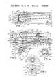
- FIGS. 1 and 2 when joined together along line A--Ashow a central vertical sectional view of a powder spray gun constructed in accordance with the present invention, the handle of the gun being broken away;
- FIG. 3is a sectional view taken on line 3--3 of FIG. 2;
- FIG. 4is a sectional view taken on line 4--4 of FIG. 2;
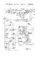
- FIG. 5is a control diagram for the spray gun, in accordance with the invention.
- the guncomprises a tubular barrel 10 made of an insulating material and carrying a spray cap 11 mounted in a front barrel portion 14 to which the barrel 10 is screwed on the outside and the spray cap 11 on the inside.
- the barrel 10is connected to a rear barrel portion 20 to which various conduits for electrical energy and air are connected and which is carried by a grounded metallic handle 13.
- the rear barrel portion 20has a first passage 22 therein to which a powder hose 23 is connected at the rear and a powder tube 24 is connected at the front.
- the tube 24terminates at the front barrel portion 14 and its contents are discharged into a central powder passage 25 in the spray cap 11.
- This powder carrying air streampasses around a diffuser assembly indicated generally at 26 which is carried centrally of the powder passage 25 and which, in turn, carries a needle charging electrode as hereinafter described.
- the charging electrodeis surrounded with an air washing passage which will also be described later.
- a connector element 27 in the rear barrel portion 20to which an air tube 28 is connected, as well as the powder hose 23 as above described.
- an air tube 28Within the air tube 28 there is contained a high voltage charging cable 29, and a ground wire which has been omitted and the function of which is indicated merely by the conventional designation for grounding the handle 13.
- the tube 28itself contains air at a suitable pressure for supplying the vortex passages of the gun as will be hereinafter described.
- the inlet air line 30connects radially to a gun passage 32 which carries air to supply the air washing passage and also connects to an annulus 33 formed as a groove in the rear barrel 20, from which annulus there is a radial passage 32a leading to the rear of a regulator valve 34 contained in the handle portion of the gun.
- the regulatoritself is shown best in FIG. 2.
- the gun regulator 34comprises a spring pressed ball valve 35 adapted to be moved away from its seat by a stem 36 carried by a spring pressed piston 37, the piston, in turn, being operated by a trigger 38 and an operating stem 39 connected to a cup 40 which is connected by a spring 41 to the piston 37.
- a small air relief passage 42is drilled through the piston 37 and connects to an exhaust passage 43 so that there is a bleed flow of air through the regulator from the control air outlet line 44 when the valve 35 is on its seat.
- the air at regulated pressuredependent on the pressure imposed by the trigger on the spring 41 then, appears beneath the valve 35 and at an internal passage 44 which connects to an annular passage 45 and, in turn, a radial passage 46.
- the radial passage 46is drilled in the rear barrel portion 20 and connects to the control air outlet tube 31.
- the tube 31carries control air at a pressure determined by the position of the trigger 38 and, hence, the force against the regulator ball valve 35.
- the pressure of the control airis at the command of the gun operator and is used to determine whether the gun operates at the first or second condition of operation hereinafter described.
- the vortex air passageconstitutes a drilled passage 47 (shown in dotted lines) leading from the interior of the tube 28 into an interior tubular passage 48 through the rear gun barrel 20. This passage communicates with the space 49 within the tubular barrel of the gun where it passes forwardly to the front barrel assembly.
- the front barrel assembly 14, as shown in FIG. 1,receives the powder tube 24 and a tube 32b which connects to passage 32 leading from the air supply as hereinafter described to carry the air washing air supply.
- the spray cap 11has disposed therein a series of vortex air passages which are designated 50. These passages enter the central powder gun discharge passage 25 tangentially thereof and cause the powder-carrying air stream to assume a whirling movement as is known in the art.
- the air for the vortex air passagesis taken from the vortex air space 49 within the barrel by suitable connections 51-52 in the front barrel portion 14 and the spray cap 11.
- the central diffuser assembly 26is carried by a series of radial spokes 53 depending from the front barrel assembly 14. Electrode shielding air is taken from the main air inlet tube 30 via tube 32b and thence through a forwardly directed passage 54 in the front barrel portion 14 and then a radial passage 55 in one of the supporting spokes 53 of the diffuser assembly.
- the electrode air passageitself comprises a small forwardly directed air passage 56 in the center of the diffuser assembly 26.
- a charging electrode 60comprises a needle element which is supported in the diffuser assembly 26 and which is connected by any suitable electrical connections 61 to a resistor 62 which is sealed within a tube 63 and which connects at its rear end to the high voltage cable 29 which extends through the rear barrel assembly 20 and is carried within the tube 28.
- the entire interior of the tube 63is filled with an epoxy base dielectric gel to reduce any tendency of sparking and to seal the resistor in its housing.
- the high voltage wire or cable 29returns to the control system hereinafter described.
- the control system of the present inventioncomprises a plurality of parallel control circuits each of which is independently adjustable on a single control panel and each of which, thereafter, is selectively actuated from the spray gun regulator valve.
- Each circuitcomprises a pilot operated air valve which is made responsive to a selected pressure at the will of the operator, and a number of function valves operated by each pilot valve.
- the function pilot valvescontrol air flow from regulators adjusted by the operator and in the present embodiment are arranged to control vortex air and material feed.
- the various tubular connectionare there shown as lines extending to and from the rear barrel portion 20 of the spray gun and are numbered as in FIG. 2.
- These tubesinclude the powder-air mixture tube 23, the trigger regulator air inlet line 30, the control air outlet line 31 which carries air away from the gun body at regulated pressure, and the vortex air tube 28.
- the high voltage wire 29is also indicated.
- the powder supply systemcomprises a tank 65 in which a body of powder is maintained in a fluidized condition by air passing into the tank from an air line 66 beneath a porous separator as is known in the art. Powder is discharged from tank 65 by an inductor 67 immersed in the fluidized powder mass as is also known in the art. An air line 69 supplies air to the inductor 67 at a suitable pressure from the central system hereinafter described.
- the trigger outlet air line 31connects to each of the paralleled pilot valves, two in the form shown, being numbered 73 and 74.
- Each pilot valveis normally closed, but opens in response to the appearance of an adjusted pressure at its operating end.
- the valves per seare conventional. In the diagram it is assumed that valve 73 operates at a lower pressure than the second pilot valve 74.
- valve 73may be preset to open at a pressure of from 15 psi. to 25 psi., while valve 74 may be preset to operate at a pressure of between 20 psi. and 40 psi.
- the function valves that are controlled by the first pilot valve 73comprise a low material feed valve 75 which controls a regulated air pressure from the main air line 70 by a connection 76, the regulator therefore being indicated at 77.
- Regulator 77is adjustable, and its adjustment is made by the operator to determine the material feed required under the first spraying condition as hereinafter described.
- the valve 75is normally closed, but is shown in the open position in FIG. 5.
- a second function valve that operates in response to opening valve 73comprises a normally closed valve 78 which, when opened, passes air to a pneumatically operated switch (not shown) for the DC power supply 79, the output of which is connected to the high voltage cable 29.
- a third function valve operated by pilot valve 73comprises a "low vortex air flow" valve 81, which when opened, passes air from an adjustable low vortex air regulator 82 to a main vortex air regulator 83 and thence to the vortex air line 28.
- the main vortex air regulator 83is a diaphragm regulator in which the air output pressure depends on the magnitude of the air pressure imposed on one side of the diaphragm, the output pressure appearing on the other. Adjustment of regulator 82 determines the level of flow of vortex air at the first spraying condition.
- a fourth function valve operated by the pilot valve 73comprises a material shut-off comprising a normally open valve 84 which, when opened, cuts off the flow of powder from the source by imposing a pressure on a pneumatically closed valve 85 within the powder tank 65 adjacent the upstream end of the powder channel of inductor 67.
- valve 84When valve 84 is closed, the air exhausts from valve 85 and the powder flow will thereafter take place at a rate determined by the operator by adjustment of a material feed air regulator valve 90.
- the regulator 90is a pneumatically responsive valve which has its output pressure controlled to a level determined by the pressure on one side of its diaphragm as the case with the vortex air pressure regulator 83.
- the second pilot valve 74operates in response to a predetermined higher pressure in the control air outlet 31.
- Valve 95controls the passage of air from an adjustable high vortex air regulator 97 to the main vortex air regulator 83.
- Valve 96controls air from a high material feed regulator 98 which is also adjustable and which determines the pressure imposed on the diaphragm of regulator 90 when it is opened.
- regulator 90passes air at a first pressure determined by regulator 77 (low material feed) or by pressure determined by regulator 98 (high material feed).
- Adjustment of regulators 77 and 98are made at the control panel of the system.
- the main vortex air regulator 83passes air at a first pressure determined by regulator 82 (low vortex air flow) or at a second pressure determined by regulator 97 (high vortex air flow). Both regulators 82 and 97 are mounted on the control panel.
- the operatorfirst determines the nature of the part to be sprayed and decides whether it contains small areas that require low vortex air spraying conditions which will produce a narrow spray stream, and to what extend the part contains large flat surfaces that are best sprayed with a high vortex air flow which produces a larger spray pattern.
- the first pilot valve 73operates in response to the trigger regulator and determines when the low material and low vortex air flow function valves 75 and 81 are to be opened.
- the operatornext makes a selection of the high vortex air regulator 97 and a similar adjustment of high material feed regulator 98 to determine the spraying conditions that apply when the gun is being used to coat larger or flat surfaces.
- the second pilot valve 74operates in response to further adjustments of the trigger and determines the onset of the high spraying conditions.
- the first pilot valve 73may be turned on at, for example, 15 psi. from the trigger regulator through line 31 and the second pilot valve 74 may be turned on at, for example, 25 psi. from line 31 and the trigger regulator 34.
- the third function valve 84operated in response to pilot valve 73 actuates the material inlet valve 85 and permits fluidized powder to flow into the inductor 67.
- valve 74controls two function valves; namely, the high vortex air valve 95 which passes air from the adjusted regulator 97 to the diaphragm of the vortex air regulator 83 and, secondly, valve 96 is opened to pass air from the high material feed regulator 98 to the diaphragm of the material feed regulator 90.
- the flow of materialis then increased and the vortex air flow is also increased so that the gun sprays a larger quantity of material over a wider pattern than previously existed.
- the DC power supplyis controlled by function valve 78.
- the AC power supplyis turned on and off by a manual switch S.
- Appropriate check valvesare interposed in the system to prevent feedback from the function valves of one circuit to the other.
Landscapes
- Electrostatic Spraying Apparatus (AREA)
- Nozzles (AREA)
Abstract
Description
Claims (5)
Priority Applications (12)
| Application Number | Priority Date | Filing Date | Title |
|---|---|---|---|
| US05/506,200US3940061A (en) | 1974-09-16 | 1974-09-16 | Electrostatic spray gun for powder coating material |
| AU84562/75AAU492562B2 (en) | 1974-09-16 | 1975-09-04 | Electrostatic spray gun for powder coating material |
| DE2539627ADE2539627C2 (en) | 1974-09-16 | 1975-09-05 | Electrostatic spray gun |
| CH1181875ACH609586A5 (en) | 1974-09-16 | 1975-09-11 | |
| BE160043ABE833418A (en) | 1974-09-16 | 1975-09-15 | ELECTROSTATIC SPRAYING POWDER COATING GUN, AND ITS CONTROL |
| SE7510280ASE7510280L (en) | 1974-09-16 | 1975-09-15 | ELECTROSTATIC SPRAY GUN FOR SPRAYING POWDERED MATERIAL |
| CA235,419ACA1058857A (en) | 1974-09-16 | 1975-09-15 | Electrostatic spray gun for powder coating material |
| IT51350/75AIT1047113B (en) | 1974-09-16 | 1975-09-15 | IMPROVEMENT IN ELECTROSTATIC GUNS FOR THE DEPOSITION OF COATING POWDERS |
| FR7528232AFR2284373A1 (en) | 1974-09-16 | 1975-09-15 | ELECTROSTATIC SPRAYING POWDER COATING GUN, AND ITS CONTROL |
| JP11202175AJPS5532433B2 (en) | 1974-09-16 | 1975-09-16 | |
| BR7505963*ABR7505963A (en) | 1974-09-16 | 1975-09-16 | ELECTROSTATIC SPRAYING GUN AND PERFECTING IN A CONTROL SYSTEM FOR AN ELECTROSTATIC SPRAYING GUN |
| GB37982/75AGB1518517A (en) | 1974-09-16 | 1975-09-16 | Electrostatic spray gun for powder |
Applications Claiming Priority (1)
| Application Number | Priority Date | Filing Date | Title |
|---|---|---|---|
| US05/506,200US3940061A (en) | 1974-09-16 | 1974-09-16 | Electrostatic spray gun for powder coating material |
Publications (1)
| Publication Number | Publication Date |
|---|---|
| US3940061Atrue US3940061A (en) | 1976-02-24 |
Family
ID=24013610
Family Applications (1)
| Application Number | Title | Priority Date | Filing Date |
|---|---|---|---|
| US05/506,200Expired - LifetimeUS3940061A (en) | 1974-09-16 | 1974-09-16 | Electrostatic spray gun for powder coating material |
Country Status (11)
| Country | Link |
|---|---|
| US (1) | US3940061A (en) |
| JP (1) | JPS5532433B2 (en) |
| BE (1) | BE833418A (en) |
| BR (1) | BR7505963A (en) |
| CA (1) | CA1058857A (en) |
| CH (1) | CH609586A5 (en) |
| DE (1) | DE2539627C2 (en) |
| FR (1) | FR2284373A1 (en) |
| GB (1) | GB1518517A (en) |
| IT (1) | IT1047113B (en) |
| SE (1) | SE7510280L (en) |
Cited By (62)
| Publication number | Priority date | Publication date | Assignee | Title |
|---|---|---|---|---|
| US4039145A (en)* | 1974-09-06 | 1977-08-02 | Air-Industrie | Electrostatic powdering nozzle |
| US4106697A (en)* | 1976-08-30 | 1978-08-15 | Ppg Industries, Inc. | Spraying device with gas shroud and electrostatic charging means having a porous electrode |
| US4520949A (en)* | 1983-04-11 | 1985-06-04 | Champion Spark Plug Company | Protective housing for coating applicator |
| US4772982A (en)* | 1986-11-13 | 1988-09-20 | Hideo Nagasaka | Powder charging apparatus and electrostatic powder coating apparatus |
| US4802625A (en)* | 1986-03-13 | 1989-02-07 | Ransburg-Gema Ag | Electrostatic spray coating device for coating with powder |
| US4852810A (en)* | 1986-03-19 | 1989-08-01 | Behr-Industrieanlagen Gmbh & Co. | Apparatus for electrostatic coating of objects |
| US4989793A (en)* | 1990-02-02 | 1991-02-05 | Illinois Tool Works, Inc. | Indirect charging electrode for electrostatic spray guns |
| US5275659A (en)* | 1990-10-09 | 1994-01-04 | Nordson Corporation | Coating apparatus having a dispenser housing |
| US5320283A (en)* | 1993-01-28 | 1994-06-14 | Nordson Corporation | Robot mounted twin headed adjustable powder coating system with spray pattern direction control |
| US5341989A (en)* | 1993-02-16 | 1994-08-30 | Nordson Corporation | Electrostatic powder spray gun with hose purge adaptor |
| US5482556A (en)* | 1990-10-09 | 1996-01-09 | Nordson Corporation | Apparatus for mounting and moving coating dispensers |
| US5520735A (en)* | 1992-06-30 | 1996-05-28 | Nordson Corporation | Nozzle assembly and system for applying powder to a workpiece |
| DE19614192A1 (en)* | 1996-04-10 | 1997-10-16 | Abb Research Ltd | Dispersing system for a powder spraying device |
| US5711489A (en)* | 1994-08-18 | 1998-01-27 | Nihon Parkerizing Co., Ltd. | Electrostatic powder coating method and apparatus |
| EP0899015A1 (en)* | 1997-08-21 | 1999-03-03 | Ransburg Industrial Finishing KK | Hand-gun for powder coating comprising switch for changing the amount of discharged powder |
| US6053420A (en)* | 1996-04-10 | 2000-04-25 | Abb Research Ltd. | Dispersion apparatus and process for producing a large cloud of an electrostatically charged powder/air mixture |
| EP0899016A3 (en)* | 1997-08-29 | 2000-10-11 | Nordson Corporation | Spray gun |
| US6276618B1 (en)* | 1997-05-14 | 2001-08-21 | Nihon Parkerizing Co., Ltd. | Electrostatic powder spray gun |
| EP1238710A1 (en)* | 2001-03-08 | 2002-09-11 | Dürr Systems GmbH | Powder spraying device and powder coating process |
| US20040050946A1 (en)* | 2002-08-06 | 2004-03-18 | Clean Earth Technologies, Llc | Method and apparatus for electrostatic spray |
| US20050045753A1 (en)* | 2002-09-27 | 2005-03-03 | Milojevic Dragoslav K. | Swirl gun for powder particles |
| US20050098659A1 (en)* | 2002-09-27 | 2005-05-12 | Milojevic Dragoslav K. | Swirl gun for powder particles |
| US20060108451A1 (en)* | 2004-11-17 | 2006-05-25 | Alexander Kevin L | Indexing valve |
| US20060202060A1 (en)* | 2004-12-06 | 2006-09-14 | Alexander Kevin L | Dispensing device handle assembly |
| US20060219824A1 (en)* | 2005-04-04 | 2006-10-05 | Alexander Kevin L | Hand-held coating dispensing device |
| US20060283386A1 (en)* | 2005-06-16 | 2006-12-21 | Alexander Kevin L | In-gun power supply control |
| US20060292271A1 (en)* | 2005-06-27 | 2006-12-28 | Peter King | Spray coating method and apparatus |
| US20070080243A1 (en)* | 2005-10-12 | 2007-04-12 | Alexander Kevin L | Material dispensing apparatus |
| USD545943S1 (en) | 2006-03-14 | 2007-07-03 | Illinois Tool Works Inc. | Coating material dispensing device |
| US20070194157A1 (en)* | 2002-08-06 | 2007-08-23 | Clean Earth Technologies, Llc | Method and apparatus for high transfer efficiency electrostatic spray |
| US7296759B2 (en) | 2004-11-19 | 2007-11-20 | Illinois Tool Works Inc. | Ratcheting retaining ring |
| US20080217437A1 (en)* | 2007-03-06 | 2008-09-11 | Spraying Systems Co. | Optimized Method to Drive Electric Spray Guns |
| US7455249B2 (en) | 2006-03-28 | 2008-11-25 | Illinois Tool Works Inc. | Combined direct and indirect charging system for electrostatically-aided coating system |
| US20090224076A1 (en)* | 2008-03-10 | 2009-09-10 | Altenburger Gene P | Circuit Board Configuration for Air-Powered Electrostatically Aided Coating Material Atomizer |
| WO2009114296A1 (en) | 2008-03-10 | 2009-09-17 | Illinois Tool Works Inc. | Controlling temperature in air-powered electrostatically aided coating material atomizer |
| WO2009114322A1 (en) | 2008-03-10 | 2009-09-17 | Illinois Tool Works Inc. | Sealed electrical source for air-powered electrostatic atomizing and dispensing device |
| WO2009114295A1 (en) | 2008-03-10 | 2009-09-17 | Illinois Tool Works Inc. | Method and apparatus for retaining highly torqued fittings in molded resin or polymer housing |
| USD608858S1 (en) | 2008-03-10 | 2010-01-26 | Illinois Tool Works Inc. | Coating material dispensing device |
| WO2010132154A2 (en) | 2009-05-12 | 2010-11-18 | Illinois Tool Works Inc. | Seal system for gear pumps |
| US7918409B2 (en) | 2008-04-09 | 2011-04-05 | Illinois Tool Works Inc. | Multiple charging electrode |
| US7926748B2 (en) | 2008-03-10 | 2011-04-19 | Illinois Tool Works Inc. | Generator for air-powered electrostatically aided coating dispensing device |
| US8770496B2 (en) | 2008-03-10 | 2014-07-08 | Finishing Brands Holdings Inc. | Circuit for displaying the relative voltage at the output electrode of an electrostatically aided coating material atomizer |
| US20180369878A1 (en)* | 2017-06-26 | 2018-12-27 | Citic Dicastal Co., Ltd | Automatic powder cleaning system for mixed-line hub bolt holes and combined powder cleaning gun |
| CN111545368A (en)* | 2020-05-15 | 2020-08-18 | 潍坊东方钢管有限公司 | Lengthened electrostatic powder spray gun device |
| US11406771B2 (en) | 2017-01-10 | 2022-08-09 | Boston Scientific Scimed, Inc. | Apparatuses and methods for delivering powdered agents |
| US11433223B2 (en) | 2016-07-01 | 2022-09-06 | Boston Scientific Scimed, Inc. | Delivery devices and methods |
| US11642281B2 (en) | 2018-10-02 | 2023-05-09 | Boston Scientific Scimed, Inc. | Endoscopic medical device for dispensing materials and method of use |
| US20230166280A1 (en)* | 2021-12-01 | 2023-06-01 | Zeus Co., Ltd. | Fluid spray device for processing substrate |
| US11701448B2 (en) | 2018-01-12 | 2023-07-18 | Boston Scientific Scimed, Inc. | Powder for achieving hemostasis |
| US11766546B2 (en) | 2018-01-31 | 2023-09-26 | Boston Scientific Scimed, Inc. | Apparatuses and methods for delivering powdered agents |
| US11833539B2 (en) | 2018-10-02 | 2023-12-05 | Boston Scientific Scimed, Inc. | Fluidization devices and methods of use |
| US11918780B2 (en) | 2019-12-03 | 2024-03-05 | Boston Scientific Scimed, Inc. | Agent administering medical device |
| US11931003B2 (en) | 2019-12-03 | 2024-03-19 | Boston Scientific Scimed, Inc. | Medical devices for agent delivery and related methods of use |
| US12053169B2 (en) | 2019-12-03 | 2024-08-06 | Boston Scientific Scimed, Inc. | Devices and methods for delivering powdered agents |
| US12083216B2 (en) | 2020-02-18 | 2024-09-10 | Boston Scientific Scimed, Inc. | Hemostatic compositions and related methods |
| US12102749B2 (en) | 2020-01-06 | 2024-10-01 | Boston Scientific Scimed, Inc. | Agent delivery systems and methods of using the same |
| US12151436B2 (en) | 2020-11-05 | 2024-11-26 | Arcam Ab | Blast nozzles for additive manufacturing and methods for using the same |
| US12285539B2 (en) | 2020-04-17 | 2025-04-29 | Boston Scientific Scimed, Inc. | Hemostatic compositions and related methods |
| US12290250B2 (en) | 2020-03-06 | 2025-05-06 | Boston Scientific Scimed, Inc. | Devices and methods for delivering powdered agents |
| US12290628B2 (en) | 2020-03-24 | 2025-05-06 | Boston Scientific Scimed, Inc. | Agent delivery systems and methods of using the same |
| US12337139B2 (en) | 2019-12-03 | 2025-06-24 | Boston Scientific Scimed, Inc. | Medical devices for agent delivery and related methods of use |
| US12370353B2 (en) | 2019-12-20 | 2025-07-29 | Boston Scientific Scimed, Inc. | Agent delivery device |
Families Citing this family (9)
| Publication number | Priority date | Publication date | Assignee | Title |
|---|---|---|---|---|
| US3964683A (en)* | 1975-09-02 | 1976-06-22 | Champion Spark Plug Company | Electrostatic spray apparatus |
| CH620600A5 (en)* | 1977-05-12 | 1980-12-15 | Alex Hengartner | |
| GB2087264A (en)* | 1980-11-19 | 1982-05-26 | Graco Inc | A speed control apparatus for operating a centrifugal atomiser |
| JPS58183958A (en)* | 1982-04-13 | 1983-10-27 | ノ−ドソン・コ−ポレ−シヨン | Blow painting apparatus and method |
| DE3608426C3 (en)* | 1986-03-13 | 1994-11-24 | Gema Volstatic Ag | Electrostatic spraying device for coating powder |
| DE3926624A1 (en)* | 1989-08-11 | 1991-02-14 | Gema Ransburg Ag | ELECTROSTATIC POWDER COATING DEVICE |
| WO2008140663A2 (en) | 2007-05-09 | 2008-11-20 | Nordson Corporation | Nozzle with internal filter |
| DE102011011054B4 (en)* | 2011-02-11 | 2023-01-26 | Thomas Mayer | Process for the treatment of compressed air and device for the treatment of compressed air |
| CN112718281B (en)* | 2019-10-14 | 2022-07-19 | 上海中国弹簧制造有限公司 | Spring electrostatic powder spraying system |
Citations (13)
| Publication number | Priority date | Publication date | Assignee | Title |
|---|---|---|---|---|
| US2302289A (en)* | 1938-12-06 | 1942-11-17 | Union Oil Co | Electrified spray method and apparatus |
| US2504117A (en)* | 1945-08-24 | 1950-04-18 | Eclipse Air Brush Co | Method of spraying multicolored coatings |
| US2743963A (en)* | 1954-05-11 | 1956-05-01 | Vilbiss Co | Spray gun air cap |
| CH339943A (en)* | 1955-01-27 | 1959-07-31 | Notz Gottlieb | Device for the continuous application of color strips on road surfaces, sports fields or the like |
| US3061198A (en)* | 1960-05-31 | 1962-10-30 | Westinghouse Electric Corp | Method and apparatus for metering slurry |
| FR1325474A (en)* | 1962-06-19 | 1963-04-26 | Comm Materiel Et D Outil Soc I | Further training in paint guns or the like |
| US3179849A (en)* | 1964-07-15 | 1965-04-20 | Simco Co Inc | Shockless ionizing air nozzle |
| US3292860A (en)* | 1963-10-28 | 1966-12-20 | Ransburg Electro Coating Corp | Electrostatic spray coating apparatus |
| US3332623A (en)* | 1964-12-14 | 1967-07-25 | Donald A Gallant | Atomizer |
| FR1524334A (en)* | 1967-03-31 | 1968-05-10 | Prosyn | Advanced device for spraying all liquids |
| US3473735A (en)* | 1968-04-25 | 1969-10-21 | Ransburg Electro Coating Corp | Electrostatic coating apparatus |
| US3630441A (en)* | 1970-10-30 | 1971-12-28 | Tunzini Sames | Electrostatic spraying apparatus |
| US3659151A (en)* | 1968-12-17 | 1972-04-25 | Tunzini Sames | Apparatus for covering an object with a layer of powder |
Family Cites Families (11)
| Publication number | Priority date | Publication date | Assignee | Title |
|---|---|---|---|---|
| CH399257A (en)* | 1960-09-19 | 1966-03-31 | Ransburg Electro Coating Corp | Process for the electrostatic application of coating material and device for its implementation |
| US3169882A (en)* | 1960-10-05 | 1965-02-16 | Ransburg Electro Coating Corp | Electrostatic coating methods and apparatus |
| US3326182A (en)* | 1963-06-13 | 1967-06-20 | Inoue Kiyoshi | Electrostatic spray device and method |
| DE1906934U (en)* | 1964-08-17 | 1964-12-17 | Hans Behr | DEVICE FOR OPTIONAL DUSTING AND APPLYING DIFFERENT SUBSTANCES |
| US3516608A (en)* | 1968-07-10 | 1970-06-23 | Henry D Bowen | Electrostatic nozzle |
| US3589607A (en)* | 1969-05-28 | 1971-06-29 | Gourdine Systems Inc | Electrostatic spray gun having an adjustable spray material orifice |
| US3635401A (en)* | 1969-10-27 | 1972-01-18 | Gourdine Coating Systems Inc | Electrostatic spraying methods and apparatus |
| US3740612A (en)* | 1971-05-28 | 1973-06-19 | Champion Spark Plug Co | Apparatus for coating with electrostatically charged particulate materials |
| FR2216775A6 (en)* | 1973-02-01 | 1974-08-30 | Air Ind | |
| FR2208312A5 (en)* | 1972-11-27 | 1974-06-21 | Air Ind | |
| DE7408830U (en)* | 1974-03-13 | 1974-08-22 | Mueller E Kg | Device for the electrostatic coating of objects with liquid or powder coating material |
- 1974
- 1974-09-16USUS05/506,200patent/US3940061A/ennot_activeExpired - Lifetime
- 1975
- 1975-09-05DEDE2539627Apatent/DE2539627C2/ennot_activeExpired
- 1975-09-11CHCH1181875Apatent/CH609586A5/xxnot_activeIP Right Cessation
- 1975-09-15ITIT51350/75Apatent/IT1047113B/enactive
- 1975-09-15SESE7510280Apatent/SE7510280L/ennot_activeApplication Discontinuation
- 1975-09-15FRFR7528232Apatent/FR2284373A1/enactiveGranted
- 1975-09-15BEBE160043Apatent/BE833418A/ennot_activeIP Right Cessation
- 1975-09-15CACA235,419Apatent/CA1058857A/ennot_activeExpired
- 1975-09-16JPJP11202175Apatent/JPS5532433B2/janot_activeExpired
- 1975-09-16GBGB37982/75Apatent/GB1518517A/ennot_activeExpired
- 1975-09-16BRBR7505963*Apatent/BR7505963A/enunknown
Patent Citations (13)
| Publication number | Priority date | Publication date | Assignee | Title |
|---|---|---|---|---|
| US2302289A (en)* | 1938-12-06 | 1942-11-17 | Union Oil Co | Electrified spray method and apparatus |
| US2504117A (en)* | 1945-08-24 | 1950-04-18 | Eclipse Air Brush Co | Method of spraying multicolored coatings |
| US2743963A (en)* | 1954-05-11 | 1956-05-01 | Vilbiss Co | Spray gun air cap |
| CH339943A (en)* | 1955-01-27 | 1959-07-31 | Notz Gottlieb | Device for the continuous application of color strips on road surfaces, sports fields or the like |
| US3061198A (en)* | 1960-05-31 | 1962-10-30 | Westinghouse Electric Corp | Method and apparatus for metering slurry |
| FR1325474A (en)* | 1962-06-19 | 1963-04-26 | Comm Materiel Et D Outil Soc I | Further training in paint guns or the like |
| US3292860A (en)* | 1963-10-28 | 1966-12-20 | Ransburg Electro Coating Corp | Electrostatic spray coating apparatus |
| US3179849A (en)* | 1964-07-15 | 1965-04-20 | Simco Co Inc | Shockless ionizing air nozzle |
| US3332623A (en)* | 1964-12-14 | 1967-07-25 | Donald A Gallant | Atomizer |
| FR1524334A (en)* | 1967-03-31 | 1968-05-10 | Prosyn | Advanced device for spraying all liquids |
| US3473735A (en)* | 1968-04-25 | 1969-10-21 | Ransburg Electro Coating Corp | Electrostatic coating apparatus |
| US3659151A (en)* | 1968-12-17 | 1972-04-25 | Tunzini Sames | Apparatus for covering an object with a layer of powder |
| US3630441A (en)* | 1970-10-30 | 1971-12-28 | Tunzini Sames | Electrostatic spraying apparatus |
Cited By (87)
| Publication number | Priority date | Publication date | Assignee | Title |
|---|---|---|---|---|
| US4039145A (en)* | 1974-09-06 | 1977-08-02 | Air-Industrie | Electrostatic powdering nozzle |
| US4106697A (en)* | 1976-08-30 | 1978-08-15 | Ppg Industries, Inc. | Spraying device with gas shroud and electrostatic charging means having a porous electrode |
| US4520949A (en)* | 1983-04-11 | 1985-06-04 | Champion Spark Plug Company | Protective housing for coating applicator |
| US4802625A (en)* | 1986-03-13 | 1989-02-07 | Ransburg-Gema Ag | Electrostatic spray coating device for coating with powder |
| US4852810A (en)* | 1986-03-19 | 1989-08-01 | Behr-Industrieanlagen Gmbh & Co. | Apparatus for electrostatic coating of objects |
| US4772982A (en)* | 1986-11-13 | 1988-09-20 | Hideo Nagasaka | Powder charging apparatus and electrostatic powder coating apparatus |
| US4989793A (en)* | 1990-02-02 | 1991-02-05 | Illinois Tool Works, Inc. | Indirect charging electrode for electrostatic spray guns |
| US5275659A (en)* | 1990-10-09 | 1994-01-04 | Nordson Corporation | Coating apparatus having a dispenser housing |
| US5482556A (en)* | 1990-10-09 | 1996-01-09 | Nordson Corporation | Apparatus for mounting and moving coating dispensers |
| US5520735A (en)* | 1992-06-30 | 1996-05-28 | Nordson Corporation | Nozzle assembly and system for applying powder to a workpiece |
| US5320283A (en)* | 1993-01-28 | 1994-06-14 | Nordson Corporation | Robot mounted twin headed adjustable powder coating system with spray pattern direction control |
| US5341989A (en)* | 1993-02-16 | 1994-08-30 | Nordson Corporation | Electrostatic powder spray gun with hose purge adaptor |
| US5711489A (en)* | 1994-08-18 | 1998-01-27 | Nihon Parkerizing Co., Ltd. | Electrostatic powder coating method and apparatus |
| DE19614192A1 (en)* | 1996-04-10 | 1997-10-16 | Abb Research Ltd | Dispersing system for a powder spraying device |
| US6053420A (en)* | 1996-04-10 | 2000-04-25 | Abb Research Ltd. | Dispersion apparatus and process for producing a large cloud of an electrostatically charged powder/air mixture |
| US6276618B1 (en)* | 1997-05-14 | 2001-08-21 | Nihon Parkerizing Co., Ltd. | Electrostatic powder spray gun |
| EP0899015A1 (en)* | 1997-08-21 | 1999-03-03 | Ransburg Industrial Finishing KK | Hand-gun for powder coating comprising switch for changing the amount of discharged powder |
| EP0899016A3 (en)* | 1997-08-29 | 2000-10-11 | Nordson Corporation | Spray gun |
| US6375094B1 (en) | 1997-08-29 | 2002-04-23 | Nordson Corporation | Spray gun handle and trigger mechanism |
| US6622937B2 (en) | 1997-08-29 | 2003-09-23 | Nordson Corporation | Spray gun handle and trigger mechanism |
| US20040016832A1 (en)* | 1997-08-29 | 2004-01-29 | Schroeder Joseph G. | Spray gun |
| EP1238710A1 (en)* | 2001-03-08 | 2002-09-11 | Dürr Systems GmbH | Powder spraying device and powder coating process |
| US6913214B2 (en) | 2001-03-08 | 2005-07-05 | Behr Systems, Inc. | Powder bell purge tube |
| US20050001056A1 (en)* | 2001-03-08 | 2005-01-06 | Thomas Duerr | Powder bell purge tube |
| US20040050946A1 (en)* | 2002-08-06 | 2004-03-18 | Clean Earth Technologies, Llc | Method and apparatus for electrostatic spray |
| US20070194157A1 (en)* | 2002-08-06 | 2007-08-23 | Clean Earth Technologies, Llc | Method and apparatus for high transfer efficiency electrostatic spray |
| US7150412B2 (en) | 2002-08-06 | 2006-12-19 | Clean Earth Technologies Llc | Method and apparatus for electrostatic spray |
| US20050045753A1 (en)* | 2002-09-27 | 2005-03-03 | Milojevic Dragoslav K. | Swirl gun for powder particles |
| US20050098659A1 (en)* | 2002-09-27 | 2005-05-12 | Milojevic Dragoslav K. | Swirl gun for powder particles |
| US20060108451A1 (en)* | 2004-11-17 | 2006-05-25 | Alexander Kevin L | Indexing valve |
| WO2006054221A1 (en) | 2004-11-17 | 2006-05-26 | Illinois Tool Works Inc. | Indexing valve |
| US7296760B2 (en) | 2004-11-17 | 2007-11-20 | Illinois Tool Works Inc. | Indexing valve |
| US7296759B2 (en) | 2004-11-19 | 2007-11-20 | Illinois Tool Works Inc. | Ratcheting retaining ring |
| US20060202060A1 (en)* | 2004-12-06 | 2006-09-14 | Alexander Kevin L | Dispensing device handle assembly |
| US8893991B2 (en) | 2005-04-04 | 2014-11-25 | Finishing Brands Holdings Inc. | Hand-held coating dispenser device |
| US20060219824A1 (en)* | 2005-04-04 | 2006-10-05 | Alexander Kevin L | Hand-held coating dispensing device |
| US7757973B2 (en) | 2005-04-04 | 2010-07-20 | Illinois Tool Works Inc. | Hand-held coating dispensing device |
| US8382015B2 (en) | 2005-04-04 | 2013-02-26 | Graco, Inc. | Hand-held coating dispenser device |
| US20100276523A1 (en)* | 2005-04-04 | 2010-11-04 | Alexander Kevin L | Hand-held coating dispenser device |
| US20060283386A1 (en)* | 2005-06-16 | 2006-12-21 | Alexander Kevin L | In-gun power supply control |
| US7460924B2 (en) | 2005-06-16 | 2008-12-02 | Illinois Tool Works Inc. | In-gun power supply control |
| US20060292271A1 (en)* | 2005-06-27 | 2006-12-28 | Peter King | Spray coating method and apparatus |
| US20070080243A1 (en)* | 2005-10-12 | 2007-04-12 | Alexander Kevin L | Material dispensing apparatus |
| US7364098B2 (en) | 2005-10-12 | 2008-04-29 | Illinois Tool Works Inc. | Material dispensing apparatus |
| USD545943S1 (en) | 2006-03-14 | 2007-07-03 | Illinois Tool Works Inc. | Coating material dispensing device |
| US7455249B2 (en) | 2006-03-28 | 2008-11-25 | Illinois Tool Works Inc. | Combined direct and indirect charging system for electrostatically-aided coating system |
| US20080217437A1 (en)* | 2007-03-06 | 2008-09-11 | Spraying Systems Co. | Optimized Method to Drive Electric Spray Guns |
| US7926748B2 (en) | 2008-03-10 | 2011-04-19 | Illinois Tool Works Inc. | Generator for air-powered electrostatically aided coating dispensing device |
| US8590817B2 (en) | 2008-03-10 | 2013-11-26 | Illinois Tool Works Inc. | Sealed electrical source for air-powered electrostatic atomizing and dispensing device |
| WO2009114296A1 (en) | 2008-03-10 | 2009-09-17 | Illinois Tool Works Inc. | Controlling temperature in air-powered electrostatically aided coating material atomizer |
| WO2009114276A1 (en) | 2008-03-10 | 2009-09-17 | Illinois Tool Works Inc. | Circuit board configuration for air- powered electrostatically aided spray gun |
| US9616439B2 (en) | 2008-03-10 | 2017-04-11 | Carlisle Fluid Technologies, Inc. | Circuit for displaying the relative voltage at the output electrode of an electrostatically aided coating material atomizer |
| WO2009114295A1 (en) | 2008-03-10 | 2009-09-17 | Illinois Tool Works Inc. | Method and apparatus for retaining highly torqued fittings in molded resin or polymer housing |
| US8770496B2 (en) | 2008-03-10 | 2014-07-08 | Finishing Brands Holdings Inc. | Circuit for displaying the relative voltage at the output electrode of an electrostatically aided coating material atomizer |
| WO2009114322A1 (en) | 2008-03-10 | 2009-09-17 | Illinois Tool Works Inc. | Sealed electrical source for air-powered electrostatic atomizing and dispensing device |
| USD608858S1 (en) | 2008-03-10 | 2010-01-26 | Illinois Tool Works Inc. | Coating material dispensing device |
| US8016213B2 (en) | 2008-03-10 | 2011-09-13 | Illinois Tool Works Inc. | Controlling temperature in air-powered electrostatically aided coating material atomizer |
| US7988075B2 (en) | 2008-03-10 | 2011-08-02 | Illinois Tool Works Inc. | Circuit board configuration for air-powered electrostatically aided coating material atomizer |
| US20090224076A1 (en)* | 2008-03-10 | 2009-09-10 | Altenburger Gene P | Circuit Board Configuration for Air-Powered Electrostatically Aided Coating Material Atomizer |
| US8496194B2 (en) | 2008-03-10 | 2013-07-30 | Finishing Brands Holdings Inc. | Method and apparatus for retaining highly torqued fittings in molded resin or polymer housing |
| US7918409B2 (en) | 2008-04-09 | 2011-04-05 | Illinois Tool Works Inc. | Multiple charging electrode |
| US8225968B2 (en) | 2009-05-12 | 2012-07-24 | Illinois Tool Works Inc. | Seal system for gear pumps |
| US20100288793A1 (en)* | 2009-05-12 | 2010-11-18 | Illinois Tool Works Inc. | Seal system for gear pumps |
| WO2010132154A2 (en) | 2009-05-12 | 2010-11-18 | Illinois Tool Works Inc. | Seal system for gear pumps |
| US12048822B2 (en) | 2016-07-01 | 2024-07-30 | Boston Scientific Scimed, Inc. | Delivery devices and methods |
| US11433223B2 (en) | 2016-07-01 | 2022-09-06 | Boston Scientific Scimed, Inc. | Delivery devices and methods |
| US11406771B2 (en) | 2017-01-10 | 2022-08-09 | Boston Scientific Scimed, Inc. | Apparatuses and methods for delivering powdered agents |
| US20180369878A1 (en)* | 2017-06-26 | 2018-12-27 | Citic Dicastal Co., Ltd | Automatic powder cleaning system for mixed-line hub bolt holes and combined powder cleaning gun |
| US10639681B2 (en)* | 2017-06-26 | 2020-05-05 | Citic Dicastal Co., Ltd. | Automatic powder cleaning system for mixed-line hub bolt holes and combined powder cleaning gun |
| US11701448B2 (en) | 2018-01-12 | 2023-07-18 | Boston Scientific Scimed, Inc. | Powder for achieving hemostasis |
| US11766546B2 (en) | 2018-01-31 | 2023-09-26 | Boston Scientific Scimed, Inc. | Apparatuses and methods for delivering powdered agents |
| US12226793B2 (en) | 2018-10-02 | 2025-02-18 | Boston Scientific Scimed, Inc. | Fluidization devices and methods of use |
| US11642281B2 (en) | 2018-10-02 | 2023-05-09 | Boston Scientific Scimed, Inc. | Endoscopic medical device for dispensing materials and method of use |
| US11833539B2 (en) | 2018-10-02 | 2023-12-05 | Boston Scientific Scimed, Inc. | Fluidization devices and methods of use |
| US11931003B2 (en) | 2019-12-03 | 2024-03-19 | Boston Scientific Scimed, Inc. | Medical devices for agent delivery and related methods of use |
| US12337139B2 (en) | 2019-12-03 | 2025-06-24 | Boston Scientific Scimed, Inc. | Medical devices for agent delivery and related methods of use |
| US11918780B2 (en) | 2019-12-03 | 2024-03-05 | Boston Scientific Scimed, Inc. | Agent administering medical device |
| US12053169B2 (en) | 2019-12-03 | 2024-08-06 | Boston Scientific Scimed, Inc. | Devices and methods for delivering powdered agents |
| US12370353B2 (en) | 2019-12-20 | 2025-07-29 | Boston Scientific Scimed, Inc. | Agent delivery device |
| US12102749B2 (en) | 2020-01-06 | 2024-10-01 | Boston Scientific Scimed, Inc. | Agent delivery systems and methods of using the same |
| US12083216B2 (en) | 2020-02-18 | 2024-09-10 | Boston Scientific Scimed, Inc. | Hemostatic compositions and related methods |
| US12290250B2 (en) | 2020-03-06 | 2025-05-06 | Boston Scientific Scimed, Inc. | Devices and methods for delivering powdered agents |
| US12290628B2 (en) | 2020-03-24 | 2025-05-06 | Boston Scientific Scimed, Inc. | Agent delivery systems and methods of using the same |
| US12285539B2 (en) | 2020-04-17 | 2025-04-29 | Boston Scientific Scimed, Inc. | Hemostatic compositions and related methods |
| CN111545368A (en)* | 2020-05-15 | 2020-08-18 | 潍坊东方钢管有限公司 | Lengthened electrostatic powder spray gun device |
| US12151436B2 (en) | 2020-11-05 | 2024-11-26 | Arcam Ab | Blast nozzles for additive manufacturing and methods for using the same |
| US20230166280A1 (en)* | 2021-12-01 | 2023-06-01 | Zeus Co., Ltd. | Fluid spray device for processing substrate |
Also Published As
| Publication number | Publication date |
|---|---|
| BR7505963A (en) | 1976-08-03 |
| SE7510280L (en) | 1976-03-17 |
| GB1518517A (en) | 1978-07-19 |
| BE833418A (en) | 1975-12-31 |
| DE2539627C2 (en) | 1985-08-14 |
| IT1047113B (en) | 1980-09-10 |
| DE2539627A1 (en) | 1976-04-01 |
| AU8456275A (en) | 1977-03-10 |
| FR2284373B1 (en) | 1979-09-14 |
| JPS5532433B2 (en) | 1980-08-25 |
| CH609586A5 (en) | 1979-03-15 |
| JPS5155343A (en) | 1976-05-15 |
| FR2284373A1 (en) | 1976-04-09 |
| CA1058857A (en) | 1979-07-24 |
Similar Documents
| Publication | Publication Date | Title |
|---|---|---|
| US3940061A (en) | Electrostatic spray gun for powder coating material | |
| US4702420A (en) | Spray gun for coating material | |
| EP0164837B1 (en) | Electrostatic spray gun | |
| US3408985A (en) | Electrostatic spray coating apparatus | |
| US3169882A (en) | Electrostatic coating methods and apparatus | |
| US4214709A (en) | Electrostatic spray coating apparatus | |
| US4713257A (en) | Spraying method and device for applying a film to a workpiece | |
| US4798341A (en) | Spray gun for robot mounting | |
| US3589607A (en) | Electrostatic spray gun having an adjustable spray material orifice | |
| US4380320A (en) | Electrostatic powder spray gun nozzle | |
| US5685482A (en) | Induction spray charging apparatus | |
| US4241880A (en) | Electrostatic spray gun | |
| CA1083804A (en) | Electrostatic spray apparatus | |
| US3583632A (en) | Electrostatic spray coating apparatus | |
| US5351903A (en) | Electrostatic powder paint gun with trigger control variable voltage | |
| US3504851A (en) | Electrostatic spray gun | |
| US3635401A (en) | Electrostatic spraying methods and apparatus | |
| US4182490A (en) | Electrostatic spray gun | |
| US3843052A (en) | Pneumatically assisted hydraulic spray coating apparatus | |
| US3837573A (en) | Apparatus for electrified spraying | |
| JPH0510144B2 (en) | ||
| CA1285435C (en) | Method and apparatus for electrostatic spray coating | |
| US5904294A (en) | Particle spray apparatus and method | |
| USRE31867E (en) | Electrostatic spray gun | |
| US3653592A (en) | Electrostatic spray gun construction |
Legal Events
| Date | Code | Title | Description |
|---|---|---|---|
| AS | Assignment | Owner name:CONTINENTAL ILLINOIS NATIONAL BANK, 231 SOUTH LASA Free format text:SECURITY INTEREST;ASSIGNOR:DEVILBISS COMPANY;REEL/FRAME:004837/0103 Effective date:19880227 Owner name:TRUST COMPANY OF CHICAGO, 231 SOUTH LASALLE STREET Free format text:SECURITY INTEREST;ASSIGNOR:DEVILBISS COMPANY;REEL/FRAME:004837/0103 Effective date:19880227 Owner name:CONTINENTAL ILLINOIS NATIONAL BANK,ILLINOIS Free format text:SECURITY INTEREST;ASSIGNOR:DEVILBISS COMPANY;REEL/FRAME:004837/0103 Effective date:19880227 Owner name:TRUST COMPANY OF CHICAGO,ILLINOIS Free format text:SECURITY INTEREST;ASSIGNOR:DEVILBISS COMPANY;REEL/FRAME:004837/0103 Effective date:19880227 | |
| AS | Assignment | Owner name:DEVILBISS COMPANY, THE, TOLEDO, OH, A CORP. OF DE Free format text:ASSIGNMENT OF ASSIGNORS INTEREST.;ASSIGNOR:CHAMPION SPARK PLUG COMPANY, A DE CORP.;REEL/FRAME:004842/0257 Effective date:19880307 Owner name:DEVILBISS COMPANY, THE, A CORP. OF DE,OHIO Free format text:ASSIGNMENT OF ASSIGNORS INTEREST;ASSIGNOR:CHAMPION SPARK PLUG COMPANY, A DE CORP.;REEL/FRAME:004842/0257 Effective date:19880307 | |
| AS | Assignment | Owner name:ILLINOIS TOOL WORKS, INC., A CORP. OF DE, ILLINOIS Free format text:ASSIGNMENT OF ASSIGNORS INTEREST.;ASSIGNOR:DEVILBISS COMPANY, THE;REEL/FRAME:005311/0346 Effective date:19900424 |