US3930220A - Borehole signalling by acoustic energy - Google Patents
Borehole signalling by acoustic energyDownload PDFInfo
- Publication number
- US3930220A US3930220AUS396635AUS39663573AUS3930220AUS 3930220 AUS3930220 AUS 3930220AUS 396635 AUS396635 AUS 396635AUS 39663573 AUS39663573 AUS 39663573AUS 3930220 AUS3930220 AUS 3930220A
- Authority
- US
- United States
- Prior art keywords
- frequency
- carrier
- output
- output circuit
- repeater
- Prior art date
- Legal status (The legal status is an assumption and is not a legal conclusion. Google has not performed a legal analysis and makes no representation as to the accuracy of the status listed.)
- Expired - Lifetime
Links
- 230000011664signalingEffects0.000titleabstractdescription9
- 230000008054signal transmissionEffects0.000claimsabstractdescription24
- 230000004044responseEffects0.000claimsdescription14
- 239000003990capacitorSubstances0.000description30
- 238000010586diagramMethods0.000description12
- 230000005540biological transmissionEffects0.000description10
- 238000004891communicationMethods0.000description5
- 230000008878couplingEffects0.000description4
- 238000010168coupling processMethods0.000description4
- 238000005859coupling reactionMethods0.000description4
- 238000005553drillingMethods0.000description4
- 238000010276constructionMethods0.000description3
- 229910000831SteelInorganic materials0.000description2
- 239000000969carrierSubstances0.000description2
- 230000000694effectsEffects0.000description2
- 238000000034methodMethods0.000description2
- 230000000737periodic effectEffects0.000description2
- 238000000926separation methodMethods0.000description2
- 239000010959steelSubstances0.000description2
- 230000003213activating effectEffects0.000description1
- 230000015572biosynthetic processEffects0.000description1
- 238000006243chemical reactionMethods0.000description1
- 239000003795chemical substances by applicationSubstances0.000description1
- 239000013078crystalSubstances0.000description1
- 238000006073displacement reactionMethods0.000description1
- 230000006872improvementEffects0.000description1
- 230000000977initiatory effectEffects0.000description1
- 238000009434installationMethods0.000description1
- 230000002085persistent effectEffects0.000description1
- 230000009467reductionEffects0.000description1
Images


Classifications
- E—FIXED CONSTRUCTIONS
- E21—EARTH OR ROCK DRILLING; MINING
- E21B—EARTH OR ROCK DRILLING; OBTAINING OIL, GAS, WATER, SOLUBLE OR MELTABLE MATERIALS OR A SLURRY OF MINERALS FROM WELLS
- E21B47/00—Survey of boreholes or wells
- E21B47/12—Means for transmitting measuring-signals or control signals from the well to the surface, or from the surface to the well, e.g. for logging while drilling
- E21B47/14—Means for transmitting measuring-signals or control signals from the well to the surface, or from the surface to the well, e.g. for logging while drilling using acoustic waves
- E21B47/16—Means for transmitting measuring-signals or control signals from the well to the surface, or from the surface to the well, e.g. for logging while drilling using acoustic waves through the drill string or casing, e.g. by torsional acoustic waves
Definitions
- ABSTRACTA system for signaling in either direction in a bore- [52] 340/18 FM; 340/18 CM; 340/18 NC; hole, utilizing an acoustic carrier transmitted along the 2 325/9; 175/50; 73/DIG' 6 drill pipe.
- the systememploys repeaters which are [51] II.- Cl.
- G01V 1/40Spaced at uniform intervals along the string of [58] Field of 18 18 CM; To prevent undesired loss of signal information and 181/15 TS; 1 /5/50; 325/1 9; 73/151 interference between the signals being transmitted by 6; 250/263 the repeaters, the carrier frequency is shifted, during signal transmission, at time intervals related to the [5 6] References C'ted spacing between repeaters.
- BOREHOLE SIGNALLING BY ACOUSTIC ENERGYThis invention relates to the transmission of signals in boreholes, and particularly to the transmission of signals during the drilling of such holes.
- the value of a means for transmitting information from the bottom of a borehole to the surfacehas been recognized for some time, and proposed systems have been the subjects of numerous patents.
- the use of a continuous wire line for the transmission of signalsis not desirable because this requires that the wire be withdrawn each time that a length of pipe is to be added; this is a costly interference with normal drilling procedures.
- An object of this inventionis to provide an improved acousitc energy signaling system for boreholes.
- Another objectis to provide a borehole signaling system which can be used for communication in either direction.
- a further objectis to provide a borehole signaling system using repeaters, wherein the repeaters are all identical.
- a still further objectis to provide an improved acoustic signaling system, using repeaters, which prevents interference between the signals being transmitted by the repeaters.
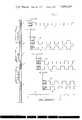
- FIG. 1is a schematic view of a drill pipe string, together with timing diagrams for illustrating the present invention during downward transmission;
- FIG. 2is a'schematic illustration of a borehole telemetry system, utilizing the principles of the present invention for upward transmission;
- FIG. 3is a block diagram of a repeater used in the invention.
- FIG. 4is a detailed circuit diagram of the repeater of FIG. 3;
- FIG. 5is a detailed circuit diagram of a demodulating unit used in the invention.
- the present applicationdescribes a method for transmitting acoustic signals in a continuous manner through the drill pipe in a borehole by inserting repeaters as necessary, at intervals such as to restore the energy level before it drops too low to be recovered from the noise background. It is known that the impedance mismatch between steel and the surrounding mud essentially prevents escape of acoustic energy into the mud. The principal loss of acoustic energy occurs at the screwed connections between pipe sections; this loss increases as the frequency is raised. At a carrier frequency of 1000 Hz, the loss has been measured as 30 db per thousand feet of pipe. For purposes of illustration, the present specification is based on a uniform repeater separation of 2000 feet, and carrier frequencies of 800 and 1000 Hz (why two carrier frequencies are mentioned here will later become apparent).
- Each repeater in the system(1) restores the signal level lost due to attenuation in the pipe, and (2) improves the signal-to-noise ratio. All repeater units used in the system are identical, and are uniformly spaced in the drill string. The distance between the top repeater and the surface varies with the hole depth, but does not exceed the interrepeater spacing.
- the numeral 1generally designates a drill pipe string which comprises a plurality of pipe sections (not separately delineated) coupled together end-to-end, in a conventional manner.
- a series of repeaters 2, 3, and 4are installed in pipe string 1 at uniform intervals of 2000 feet, for example.
- the function of each repeateris, in general, to pick up (receive) an acoustic signal (signal-modulated carrier) from the string of drill pipe, amplify it, and retransmit it as an acoustic signal along the pipe.
- the repeaters 2-4thus perform the same general or overall function as those disclosed in my above-mentioned copending application.
- repeater 3will receive 1000 Hz signals of equal amplitude from repeaters 2 and 4 (since the acoustic energy is of course transmitted as compressional waves in both directions along the pipe). Because of the time displacement (signals traveling from repeater 4, through repeater 3, through repeater 2, and back to repeater 3, as compared to signals traveling only from repeater 4 to repeater 3), there will be random cancellation, and the modulating information will be lost.
- two frequenciese.g., 800 Hz and 1000 Hz
- these frequenciesbeing alternated at time intervals such that each repeater receives only one signal.
- This signalcomes from the direction of the command signal generator 5, illustrated schematically at the upper end of the drill string 1 in FIG. 1.
- the velocity of sound in steel for the longitudinal modeis 16,000 feet per second, so the transit time between the repeaters shown in FIG. 1 is 0.125 second (assuming a uniform repeater separation of 2000 feet).
- FIG. 1sets of timing diagrams (frequency-vs-time graphs), referred 3 to the horizontal time axis 6 at the bottom of this figure, are positioned respectively in alignment with the items (2,3,4, or to which they respectively apply.
- Repeater 2begins to receive the carrier not more than 0.125 second (the acoustic transit time for 2000 feet of pipe) after the command carrier begins its 800 Hz transmission, as indicated by the IN or received timing diagram 8; the OUT or transmitted carrier follows changes in command carrier frequency thereafter, as indicated by the timing diagram 9. It is pointed out that both the IN and OUT carrier frequencies 8 and 9 of repeater 2 follow changes in the command carrier frequency 7, beginning with receipt of the 800 Hz carrier (from command generator 5) at time 0.125.
- Repeater 3is actuated 0.125 second after repeater 2 begins transmission on 800 Hz (at time 0.375; see graph 9), or not more than 0.5 second after start of the command signal (at time zero). Thereafter, the IN and OUT carriers of repeater 3 follow the changes in command carrier frequency, as indicated by graphs 10 and 11, respectively.
- repeater 4is actuated (i.e., begins to transmit the signal) 0.125 second after repeater 3 begins transmission on 800 Hz (at time 0.75; see graph 11), or not more than 0.875 second after start of the command signal. Thereafter, the IN and OUT carriers of repeater 4 follow the changes in command carrier frequency, as indicated by graphs 12 and 13, respectively.
- the purpose of shifting the carrier frequencyis to prevent interference from the transmission of the next repeater in the sequence.
- the transit timedisplaces the carrier received from the following repeater relative to the carrier traveling in the desired direction. From FIG. 1 (left-hand portion), it may be seen that either carrier frequency emitted by repeater 3 requires 0.125 second to reach repeater 2 (transit time between 2 and 3 is 0.125 second); the input of repeater 2 (graph 8) is at that time always tuned to the alternate frequency (compare graph 11 with graph 8). Likewise, repeater 3 cannot receive the carrier transmitted by repeater 4 (compare graph 13 with graph 10, the transit time between repeaters 3 and 4 also being 0.125 second).
- the output of repeater 4(graph 13) requires 0.25 second (twice the adjacent-repeater transit time of 0.125 second) to reach the input of repeater 2, and always arrives when the input filter of repeater 2 (see graph 8) is tuned to the other frequency.
- the direction of transmissioncan be reversed by turning on the command signal at the desired initiating end of the drill string, and turning off the command signal at the other end.
- Informationmay be transmitted as soon as the required frequency turn-on sequence (such as previously described, in connection with FIG. 1) has been established.
- FIG. 2One form of a borehole information transmission system (borehole telemetry system) is illustrated in block diagram form in FIG. 2.
- a sensor 14 for measuring information downholedevelops a signal which is converted to pulse width coding by means of a pulse width modulator unit 15.
- An example of such a sensor (responsive to inclination of a drilling element) developing pulse width modulationis described in my copending application, Ser. No. 396,627, filed Sept. 12, 1973, entitled High Side Meter.
- Another sensor 16 responsive to downhole informationmay develop analog potentials or currents which are converted to digital coding by means of an analog-to-digital converter 17. Any number of coded signals are selected in sequence by a multiplex switch 18 controlled by a clock unit 19.
- the command signal generator 5which is similar to the command generator 5 in FIG. 1, produces a carrier which alternates between 800 and 1000 Hz, as previously described in connection with FIG. 1 (time-frequency graph 7).
- This carrieris fed to a frequency modulator 20, as is the signal from the multiplexer 18.
- the coded signal(from 18) introduces an additional smaller shift in frequency (maximum shift 50 Hz).
- the frequency shift keyed (FSK) output of modulator 20is applied to a sound source 21, for conversion into acoustic energy, which is transmitted as compressional waves toward the surface along drill string 1.
- the sound source 21is preferably of the construction disclosed in my Telemetering System for Boreholes application. An off" position could be included in the switching sequence of multiplex switch 18, to turn off the command signal from 5', thus to permit command instructions to be transmitted from the surface.
- Repeaters 2' and 3'similar to the repeaters 24 of FIG. 1, are utilized between the downhole sound source 21 and the surface, to compensate for attenuation in the pipe and to improve the signal-noise ratio.
- the acoustic signal traveling along the drill pipeis picked up by a signal pickup or receiver 22 (illustrated as a piezoelectric crystal) which is acoustically coupled to the drill string.
- the receiver 22is preferably a crystal-type receiver, as described in my Telemetering System for Boreholes application.
- the signal received at the surfaceis transmitted by means of a radio link involving a transmitter T and a receiver R to the demodulating unit 23.
- the received signalis fed to a frequency-controlled switch 24 (to be later described in more detail) which controls the center frequency of an active filter 25 to which the received signal is also fed.
- the filter 25is controlled (by switch 24) to make its center frequency either 800 Hz or 1000 Hz, depending upon the frequency of the incoming signal.
- the output of the filter 25is fed to a balanced modulator 26, to which is also applied (for mixing with the 800 Hz or 1000 Hz output of filter 25) a 100 Hz wave from a local oscillator 27.
- the balanced modulatorthen acts to produce, at its output, sidebands of 700 and 900 Hz (when the received carrier is 800 Hz) or sidebands of 1100 and 900 Hz (when the received carrier is 1000 HZ).
- the output of the modulator 26is fed to the input of a 900 Hz filter 28, which passes in each case the 900 Hz sideband to the phase-locked loop 29 (later described in more detail), the control voltage output of which, at 30, provides a reproduction of the modulation (digital or pulse width modulation) being transmitted from downhole in FIG. 2.
- the periodic shift in carrier frequencyis eliminated (the output of filter 28 being 900 Hz, regardless of whether the incoming carrier is centered at 800 Hz or at 1000 Hz), and the smaller frequency shifts are converted to coded signals which duplicate the downhole modulating signals.
- the apparatus at the surfacewould have to include a carrier command module, generally similar to unit 5 previously described, with the coded instructions, and a sound source (similar to sound source 21) in contact with the pipe.
- the downhole apparatuswould then have to include a sound pickup (like pickup 22) and a duplicate of the surface demodulating unit 23.
- the surface unitdoes not transmit in response to a received signal. It only demodulates the received signal (as in FIG. 2), or else sends a command signal when the repeater transmitters are to be turned on in sequence (as in FIG. 1). Reduced spacing between the top repeater and the surface (in FIG. 1) merely reduces the turn-on time.
- FIGS. 3 and 4provide additional details of the arrangement at one of the repeaters (2, 3, or 4 in FIG. 1, or 2', 3 in FIG. 2), FIG. 3 being an illustration in block diagram form and FIG. 4 showing the essential circuit details.
- the acoustic signal picked up from the drill string by the acoustic pickup 22(which may be of the same type as pickup 22, previously referred to in connection with FIG. 2) is fed through a preamplifier 31 to the input side of an input filter 32, which is an active filter of a type whose center frequency can be shifted by changing one resistor value.
- this shiftable center frequencyis represented as effected by one arm or pole 33 of a frequencyactuated switch 34 to which is supplied the received signal (output of preamplifier 31) by way of a limiter 35.
- the arm 33is coupled by way of a lead 36 to filter 32, for controlling the center frequency of the latter.
- the arm 33has an 800 Hz contact position 37 and a 1000 Hz contact position 38, as well as an intermediate position (illustrated) which it assumes in the absence of an input signal.
- the frequency-actuated switch 34is actuated (as indicated by the dotted line 39) in accordance with the frequency of the output of limiter 35.
- the active filter 32has a roll-off of 40 db for Hz.
- the input filter 32is tuned to 800 Hz.
- the output of filter 32is connected as one input for a balanced modulator 40, the second input for which is supplied by a local oscillator 41 operating at 200 Hz.
- the output of modulator 40is fed to the input side of an output filter 42, which is similar to the input filter 32.
- the shiftable center frequencyis represented as effected by a second arm or pole 43 of the frequency-actuated switch 34. Arm 43 is coupled by way of a lead 44 to filter 42, for
- the arm 43has a 1000 Hz contact position 45 (analogous to the 800 Hz position 37 of arm 33) and an 800 Hz contact position 46 (analogous to the I000 I-Iz position 38 of arm 33), as well as a no-signal intermediate position. in the absence of an input signal, the output filter 42 is tuned to 1000 Hz.
- the output of filter 42is fed to a phase-locked loop 47, whose output is applied through a power amplifier 48 to a sound source 21', similar to sound source 21 (previously mentioned).
- a sound source 21'Similar to sound source 21 (previously mentioned).
- the sound source 21'is turned off, by means of a squelch voltage provided in power amplifier 48 (which otherwise drives the sound source 21').
- the center of the capture range of the phase-locked loopis varied by changing a capacitance value.
- This variable capture frequencyis represented as effected by a third arm or pole 49 of the frequency-actuated switch 34.
- Arm 49is coupled by way of a lead 50 to the phase-locked loop 47, for controlling the capture frequency of the latter.
- the arm 49has a 1000 Hz contact position 51 (analogous to the 1000 Hz position 45 of arm 43) and an 800 Hz contact position 52 (analogous to the 800 Hz position 46 of arm 43), as well as a no-signal intermediate position.
- the arms 33, 43, and 49 of switch 34all are operated together (as indicated by the dotted-line coupling 39), in the manner of a three-pole, double-throw switch; thus, the arm 33 moves to its 1000 Hz contact 38 along with the movement of arm 43 to its 800 Hz contact 46 and with the movement of arm 49 to its 800 Hz contact 52; likewise, the arm 33 moves to its 800 Hz contact 37 along with the movement of arm 43 to its 1000 Hz contact 45 and with the movement of arm 49 to its 1000 Hz contact 51.
- the input filter 32is tuned to 800 Hz (i.e., its center frequency is 800 HZ).
- 800 Hzi.e., its center frequency is 800 HZ.
- this signalpasses through filter 32, developing sidebands of 600 Hz and 1000 Hz in the balanced modulator 40.
- the output filter 42is then tuned to 1000 Hz, so the 1000 Hz sideband is passed by filter 42, is rectified by a rectifier 53, developing a voltage across the RC network 54 which overrides the squelch (in 48), activating 7 the sound source 21, which then transmits the 1000 Hz frequency (fed to such source by way of loop 47 and amplifier 48).
- the phase-locked loop 47follows the most persistent frequency within its capture range, and gives substantial reduction of random noise
- the frequency-actuated switch 34(receiving the incoming signal through preamplifier 31 and limiter 35), in effect, moves the arms 33, 43, and 49 to their right-hand contacts 38, 46, and 52, respectively.
- Arm 33, on contact 38changes the center frequency of input filter 32 to 1000 Hz.
- the 1000 Hz signalthen passes through filter 32, developing sidebands of 800 and 1200 H2 in the balanced modulator 40.
- Filter 42then passes the 800 Hz sideband from modulator 49, and the 800 Hz frequency is transmitted from sound source 21', in amplified form.
- the frequency-actuated switch 34(receiving the incoming signal through preamplifier 31 and limiter 35), in effect, moves the arms 33, 43, and 49 to their left-hand contacts 37, 45, and 51, respectively. Arm 33, on contact 37, changes the center frequency of input filter 32 to 800 Hz.
- the 800 Hz signalthen passes through filter 32 developing sidebands of 600 and 1000 H2 in the balanced modulator 40.
- Arm 43, on contact 45changes the center frequency of output filter 42 to 1000 HZ
- arm 49, on contact 51changes the center of the phase-locked loop 47 capture range to 1000 Hz.
- Filter 42then passes the 1000 Hz sideband from modulator 40, and the I000 l-lz frequency is transmitted from sound source 21, in amplified form.
- FIG. 4is a detailed circuit diagram of a repeater used in'the system of this invention.
- the wave (acoustic or sonic frequency carrier of 800 Hz or 1000 Hz, frequency modulated by a signal) picked up by the pickup or receiver 22is fed through a coupling condenser 55 to the input of the preamplifier 31, which is an operational amplifier connected in a conventional manner, as illustrated.
- the amplified voltageis fed over a resistor 57 and a capacitor 58 (both included in the input active filter 32) to one input 59 of an operational amplifier 60, which forms the active part of the active filter 32.
- a resistor 62is connected to the reference potential point (ground).
- a resistor 63 and a capacitor 64are connected in series between amplifier input 59 and junction point 61.
- Output from the input active filter 32is supplied by means of a transformer 65 to one pair of input terminals of the balanced modulator 40, and the local oscillator 41 (frequency, 200 Hz) is connected to the other pair of input terminals of modulator 40.
- the output of the modulator 40(600 Hz and 1000 Hz, when the input at 65 is 800 Hz; 800 Hz and 1200 Hz, when the input at 65 is 1000 Hz) is fed over a resistor 66 and a capacitor 67 to one input 68 of the operational amplifier 69 (similar to amplifier 60) of the output active filter 42. From the common junction point 70 of elements 66 and 67, a resistor 71 is connected to ground. A resistor 72 and a capacitor 73 are connected in series between amplifier input 68 and junction point 70.
- phase-locked loop 47Included in the phase-locked loop 47 are a phase discriminator 74, a low-pass filter 75, and a voltagecontrolled oscillator 76.
- Output from the output active filter 42(1000 Hz or 800 Hz) provides one input for the phase discriminator 74, output from the voltagecontrolled oscillator 76 providing the other input for the phase discriminator.
- the phase discriminator outputrepresentative of frequency and/or phase differences between the filter output and the oscillator output, is passed through the low-pass filter 75 and then applied to the voltage-controlled oscillator 76 to phaselock the latter with the output of filter 42.
- a capacitor 77coupled to the voltage-controlled oscillator 76, determines the center of the phase-locked loop capture range; this range is centered at 1000 Hz if capacitor 77 alone is in the circuit.
- the system of this inventionbe able to communicate in either direction, along the drillpipe.
- the directiondepends on the location of the command signal source. If the command signal originates downhole (as in FIG. 2), it sets up the time sequence of filter frequencies to permit transmission toward the surface. If the command signal originates at the surface (as in FIG. 1), the time sequence is set up (as described in connection with FIG. 1) to send control signals downhole. The command is downhole (signals toward the surface) unless pre-empted by an overriding command signal at the surface, introduced when the sound sources 21,21, etc. are turned off (in response to the cessation of a command signal from downhole).
- Operation of the frequency-actuated switch 34depends upon the frequency discriminator formed by two resistors 81 and 82 and two capacitors 83 and 84.
- Capacitor 84 and resistor 82are connected in series across the output of limiter 35, and resistor 81 and capacitor 83 are also connected in series across thelimiter output.
- the voltage across resistor 82is taken off by way of a capacitor 85 and is rectified in a negative sense by diode 86 to provide a voltage across load resistor 87 which is applied to the direct input 88 of an operational amplifier 89.
- the voltage across capacitor 83is taken off by way of a capacitor 90 and is rectified in a positive sense by diode 91 to also provide a voltage across the combining load resistor 87.
- the values of components 8184are chosen so that, at 900 Hz, the impedance of resistor82 is equal to the impedance of capacitor 84, and the impedance of resistor 81 is equal to the impedance of capacitor 83.
- the impedance of resistor 82is less than that of capacitor 84, while the impedance of capacitor 83 is greater than that of resistor 81. Therefore, at 800 Hz. the voltage across capacitor 83 is greater than the voltage across resistor 82, so the net rectified voltage on the direct input of amplifier 89 is positive and the amplifier output is positive.
- the impedances of capacitors 84 and 83are less than those of resistors 82 and 81, the net rectified voltage on the direct amplifier input is negative, and the amplifier output voltage is negative.
- a pair of diodes 92 and 93are poled as illustrated and connected in series aiding, between the output of amplifier 89 and ground, and from the common junction of these two diodes a resistor 94 is coupled through a capacitor 95 to the ungrounded end of resistor 71 (in the output active filter 42.)
- the output voltage of amplifier 89is positive and diodes 92 and 93 conduct, connecting resistor 94 in parallel with resistor 71 of the output filter 42, through capacitor 95.
- resistor 62 (in input filter 32) and resistor 71 (in output filter 42) in the circuitboth filters 32 and 42 have a center frequency of 800 Hz.
- Resistor 94is chosen to tune the output filter 42 to 1000 Hz when connected in parallel with resistor 71; this occurs, as stated, when-the incoming frequency is 800 Hz.
- a pair of diodes 96 and 97, poled as illustrated,are connected in series aiding between the output of amplifier 89 and ground, and from the common junction of these two diodes a resistor 98 is coupled through a capacitor 99 to the ungrounded end of resistor 62 (in the input active filter 32).
- the output of amplifier 89is negative and diodes 96 and 97 conduct, connecting resistor 98 in parallel with resistor 62 of the input filter 32, through capacitor 99.
- Resistor 98tunes the input filter 32 to 1000 Hz when connected in parallel with resistor 62. Since resistor 94 is now no longer connected into the circuit, the output filter 42 returns to 800 Hz center frequency.
- capacitor 102is connected to the high side of capacitor 77 (which latter is in circuit with the voltage-controlled oscillator 76), and thus essentially in parallel with capacitor 77 (when capacitor 102 is connected to ground by way of diode
- capacitor 102is added to capacitor 77, to lower the center of the capture range of the phase-locked loop 47 to 800 Hz.
- a small negative biasis applied to the inverting input 104 of amplifier 89.
- Thiscauses the amplifier output to be positive during standby (i.e., in the absence of an input signal).
- the amplifier outputis positive, there is no resistance connected in parallel with resistor 62 (in the input filter 32), so the center frequency of the input filter 32 is then 800 Hz.
- resistor 94is connected in parallel with resistor 71, so the center frequency of the output filter 42 is then 1000 Hz.
- the negative output of the discriminator 81-84(when the incoming carrier is 1000 Hz) is sufficient to override this bias (on inverting input 104).
- FIG. 2illustrates, in block diagram form, a demodulating unit 23 connected to a sound pickup 22 at the surface through a radio linkT-R.
- the circuitry of the demodulating unitisshown in more detail in FIG. 5. This circuit performs three functions: (1) it discriminates between the frequency modulated signal and amplitude modulated noise; (2) the periodic shift in carrier frequency is eliminated, and the carrier is restored to a single frequency; (3) the coded signals used to modulate the carrier are recovered in the original form.
- the incoming signalis first passed through an input active filter 25 which is tuned to either 800 or 1000 Hz by the frequency-actuated switch 24 as the carrier shifts.
- the incoming signalis supplied to the switch 24, for actuation thereof, by way of the limiter 35; the switch 24 is constructed somewhat similarly to, and operates like, the switch 34 (in FIG. 4, previously described), but for control of the center frequency of the input filter 25, only.
- the balanced modulator 26receives inputs from the local oscillator 27 (100 Hz) and from the input filter 25.
- the sideband of 900 Hzis common to both-of the above-mentioned pairs of sidebands, and is selected by the output active filter 28 which receives the modulator output.
- the output filter 28is rather similar in construction to the output filter 42 previously described, but the former is fixed-tuned to a center frequency of 900 Hz.
- phase-locked loop 29, which receives the output of filter 28,is rather similar in construction to the phase-locked loop 47 previously described, but the center of the capture range of the former is fixed at 900 Hz.v r
- the phase-locked loop 29'generates a dc. control voltage (output of phase discriminator 74', passed through low pass filter which adjusts (at 79) the voltage-controlled oscillator 76' to keep its frequency equal to that of the incoming signal (output of filter 28).
- This control voltagemust follow the frequency shifts due to the modulation downhole. Hence, it provides (at a reproduction of the digital or pulsewidth signal being transmitted from downhole (see FIG. 2).
- a repeater arrangementfor receiving and retransmitting said carrier com- 1 1 prising a signal receiver, a tunable input circuit receptive of the signal receiver output, a tunable output circuit, a signal transmitter coupled to and driven from said output circuit, and means, acting in response to thereceipt by said receiver of carrier frequency f,, to tune said input circuit to frequency f and to tune said output circuit to frequency f 2.
- said meansalso acts, in response to the receipt by said receiver of carrier frequency f to tune said input circuit to frequency f and to tune said output circuit to frequency f,.
- a signal transmission systemfor use in a borehole, comprising, at a location A: a sound source acoustically coupled to the drill pipe in said borehole for transmitting an acoustic carrier wave along such pipe, and means supplying to said source wave energy periodically shifted back and forth between two frequencies f, and f thereby to transmit along the drill pipe an acoustic carrier wave periodically shifted back and forth between frequencies f and f and at a location B spaced a pre-established distance along said drill pipe from location A: a sound pickup acoustically coupled to the drill pipe, a tunable input circuit receptive of the sound pickup output, and means acting upon the receipt by said pickup of carrier frequency f, to tune said input circuit to frequency f,.
- System of claim 3including also, at location B, a tunable output circuit associated with said input circuit, and asound transmitter acoustically coupled to the drill pipe and driven from said output circuit; said means at location B acting also, upon the receipt by said pickup of carrier frequency f,, to tune said output circuit to frequency f 7.
- a signal transmission system for boreholescomprising a command signal generator located at one end of a string of drill pipe, and a plurality of identical repeaters in said pipe string spaced from said generator and from each other, said repeaters being spaced at known, uniform distances from each other along the length of said string; said command signal generator including means for transmitting along said string a continuous acoustic carrier which is periodically shifted back and forth between two frequencies f and f2; each of said repeaters including a sound pickup acoustically coupled to the drill pipe, a tunable input circuit receptive of its respective sound pickup output, a tunable output circuit, a sound transmitter acousti- 12 cally coupled to the drill pipe and driven from its respective output circuit, and means acting upon the receipt by each pickup of carrier frequency f, to tune its respective input circuit to frequency f, and to tune its respective output circuit to frequency f,.
- each repeateralso acts, upon the receipt by its pickup of carrier frequency f-,,, to tune its respective input circuit to frequency f; and to tune its respective output circuit to frequency f,.
- each of the repeater input circuitsis an active filter
- each of the repeater output circuitsis an active filter
- each of said repeatersalso includes a shift frequency heterodyne oscillator connected to heterodyne with the output of the respective input circuit to provide a sideband frequency for application to the respective output circuit, the fre quency of the oscillator in each repeater being equal to the difference between f and f 14.
- each of the repeater input circuitsis an active filter whose center frequency depends on the value of an impedance coupled thereto, and wherein the means in each repeater changes the effective value of the corresponding input active filter impedance.
- each of the repeater input circuits and each of the repeater output circuitsis an active filter whose center frequency depends on the value of an impedance coupled respectively thereto, and wherein the means in each repeater changes the effective values of the impedances in the corresponding input and output active filters.
- each of said repeatersalso includes a phase-locked loop connected between the repeater output circuit and the repeater sound transmitter and including a voltage-controlled oscillator together with means for locking its frequency to that of the repeater output circuit output; the means in each repeater also acting upon the receipt of carrier frequency f to shift the center of the phase-locked loop capture range to frequency f 17.
- a repeater arrangementfor receiving and retransmitting said carrier com prising a signal receiver, a tunable input circuit receptive of the signal receiver output, a shift frequency heterodyne oscillator connected to heterodyne with the output of said input circuit, the frequency of said oscillator being equal to the difference between f and f a tunable output circuit, a signal transmitter coupled to and driven from said output circuit, and means, acting in response to the receipt by said receiver of carrier frequency f,, to tune said input circuit to frequency f, and to tune said output circuit to frequency f 18.
- a repeater arrangement for receiving and retransmitting said carriercomprising a signal receiver, a tunable input circuit comprising an active filter receptive of the signal receiver output, a tunable output circuit comprising an active 13 filter, a signal transmitter coupled to and driven from said output circuit, and means, acting in response to the receipt by said receiver of carrier frequency f,, to tune said input circuit to frequency f and to tune said output circuit to frequency f 19.
- a repeater arrangement for receiving and retransmitting said carriercomprising a signal receiver, a tunable input circuit comprising an active filter receptive of the signal receiver output and whose center frequency depends on the value of an impedance coupled thereto, a tunable output circuit, a signal transmitter coupled to and driven from said output circuit, and means, acting in response to the receipt by said receiver of carrier frequency f to tune said input circuit to frequency f by changing the effective value of said impedance in said input circuit and to tune said output circuit to frequency f 20.
- a repeater arrangement for receiving and retransmitting and carriercomprising a signal receiver, a tunable input circuit comprising an active filter whose center frequency depends upon the value of an impedance coupled thereto, said input circuit being receptive of the signal transmitter output, a tunable output carrier comprising an active filter whose center frequency depends upon the value of an impedance coupled thereto, a signal transmitter coupled to and driven from said output circuit, and means, acting in response to the receipt by'said receiver of carrier frequency f to tune said input circuit to frequency f and to tune said output circuit to frequency f by changing the effective values of said impedance.
- a signal transmission systemfor use in a borehole, comprising, at a location A: a sound source acoustically coupled to the drill pipe in said borehole for transmitting an acoustic carrier wave along such pipe, and means supplying to said source wave energy periodically shifted back and forth between two frequencies f and f thereby to transmit along the drill pipe an acoustic carrier wave periodically shifted back and forth between frequencies f and f and at a location B spaced a pre-established distance along said drill pipe from location A: a sound pick-up acoustically coupled to the drill pipe, a tunable input circuit comprising an active filter receptive of the sound pick-up output, a tunable output circuit comprising an active filter associated with said input circuit, a sound transmitter acoustically coupled to the drill pipe and driven from the said output circuit, and means acting upon the receipt by said pick-up of carrier frequency f to tune said input circuit to frequency f and said output circuit to frequency f and upon receipt of carrier frequency f
- a signal transmission systemfor use in a borehole, comprising, at a location A: a sound source acoustically coupled to the drill pipe in said borehole for transmitting an acousicc carrier wave along such pipe, and means supplying to said source wave energy periodically shifted back and forth between two frequencies f and f thereby to transmit along the drill pipe an acoustic carrier wave periodically shifted back and forth between frequencies f and f and at a location B spaced a pre-established distance along said drill pipe from location A: a sound pick-up acoustically coupled to the drill pipe, a tunable input circuit receptive of the sound pick-up output, a tunable output circuit associated with said input circuit, a sound transmitter acoustically coupled to the drill pipe and driven from said output circuit, means acting upon the receipt of said pick-up of carrier frequency f to tune said input circuit to frequency f and said output circuit to frequency f and upon receipt of carrier frequency f to tune said input circuit to frequency f and said output
Landscapes
- Physics & Mathematics (AREA)
- Engineering & Computer Science (AREA)
- Geology (AREA)
- Acoustics & Sound (AREA)
- Mining & Mineral Resources (AREA)
- Life Sciences & Earth Sciences (AREA)
- Remote Sensing (AREA)
- Fluid Mechanics (AREA)
- Environmental & Geological Engineering (AREA)
- Geophysics (AREA)
- General Life Sciences & Earth Sciences (AREA)
- Geochemistry & Mineralogy (AREA)
- Selective Calling Equipment (AREA)
Abstract
Description
Claims (22)
Priority Applications (2)
| Application Number | Priority Date | Filing Date | Title |
|---|---|---|---|
| US396635AUS3930220A (en) | 1973-09-12 | 1973-09-12 | Borehole signalling by acoustic energy |
| CA209,004ACA1014257A (en) | 1973-09-12 | 1974-09-11 | Borehole signaling by acoustic energy |
Applications Claiming Priority (1)
| Application Number | Priority Date | Filing Date | Title |
|---|---|---|---|
| US396635AUS3930220A (en) | 1973-09-12 | 1973-09-12 | Borehole signalling by acoustic energy |
Publications (1)
| Publication Number | Publication Date |
|---|---|
| US3930220Atrue US3930220A (en) | 1975-12-30 |
Family
ID=23568036
Family Applications (1)
| Application Number | Title | Priority Date | Filing Date |
|---|---|---|---|
| US396635AExpired - LifetimeUS3930220A (en) | 1973-09-12 | 1973-09-12 | Borehole signalling by acoustic energy |
Country Status (2)
| Country | Link |
|---|---|
| US (1) | US3930220A (en) |
| CA (1) | CA1014257A (en) |
Cited By (86)
| Publication number | Priority date | Publication date | Assignee | Title |
|---|---|---|---|---|
| US4090170A (en)* | 1975-12-17 | 1978-05-16 | Shell Oil Company | Process and apparatus for investigating the activity of a cathodic protection unit |
| DE2758770A1 (en)* | 1976-12-30 | 1978-07-20 | Sperry Sun Inc | PROCESS AND DEVICE FOR TELEMETRIC TRANSMISSION OF ACOUSTIC SIGNALS VIA A DRILL ROD IN THE DRILLING HOLE |
| US4167000A (en)* | 1976-09-29 | 1979-09-04 | Schlumberger Technology Corporation | Measuring-while drilling system and method having encoder with feedback compensation |
| US4213199A (en)* | 1978-09-20 | 1980-07-15 | The United States Of America As Represented By The Secretary Of The Navy | Acoustic data link |
| US4254481A (en)* | 1979-08-10 | 1981-03-03 | Sperry-Sun, Inc. | Borehole telemetry system automatic gain control |
| EP0033192A1 (en)* | 1980-01-21 | 1981-08-05 | Sperry Corporation | A system for the acoustic propagation of data along a borehole drilling string |
| US4293936A (en)* | 1976-12-30 | 1981-10-06 | Sperry-Sun, Inc. | Telemetry system |
| US4390975A (en)* | 1978-03-20 | 1983-06-28 | Nl Sperry-Sun, Inc. | Data transmission in a drill string |
| US4518888A (en)* | 1982-12-27 | 1985-05-21 | Nl Industries, Inc. | Downhole apparatus for absorbing vibratory energy to generate electrical power |
| US4649993A (en)* | 1985-09-18 | 1987-03-17 | Camco, Incorporated | Combination electrically operated solenoid safety valve and measuring sensor |
| US4663628A (en)* | 1985-05-06 | 1987-05-05 | Halliburton Company | Method of sampling environmental conditions with a self-contained downhole gauge system |
| US4665398A (en)* | 1985-05-06 | 1987-05-12 | Halliburton Company | Method of sampling and recording information pertaining to a physical condition detected in a well bore |
| US4675649A (en)* | 1985-09-11 | 1987-06-23 | Halliburton Company | Apparatus and method for interfacing a transducer |
| US4709234A (en)* | 1985-05-06 | 1987-11-24 | Halliburton Company | Power-conserving self-contained downhole gauge system |
| US4826577A (en)* | 1987-02-18 | 1989-05-02 | Lange Goesta | Control system for electrochemical protection on submersible metal structures |
| US4866607A (en)* | 1985-05-06 | 1989-09-12 | Halliburton Company | Self-contained downhole gauge system |
| US4992997A (en)* | 1988-04-29 | 1991-02-12 | Atlantic Richfield Company | Stress wave telemetry system for drillstems and tubing strings |
| US5056067A (en)* | 1990-11-27 | 1991-10-08 | Teleco Oilfield Services Inc. | Analog circuit for controlling acoustic transducer arrays |
| US5163521A (en)* | 1990-08-27 | 1992-11-17 | Baroid Technology, Inc. | System for drilling deviated boreholes |
| US5293937A (en)* | 1992-11-13 | 1994-03-15 | Halliburton Company | Acoustic system and method for performing operations in a well |
| US5373481A (en)* | 1992-01-21 | 1994-12-13 | Orban; Jacques | Sonic vibration telemetering system |
| US5467832A (en)* | 1992-01-21 | 1995-11-21 | Schlumberger Technology Corporation | Method for directionally drilling a borehole |
| US5592438A (en)* | 1991-06-14 | 1997-01-07 | Baker Hughes Incorporated | Method and apparatus for communicating data in a wellbore and for detecting the influx of gas |
| US5942990A (en)* | 1997-10-24 | 1999-08-24 | Halliburton Energy Services, Inc. | Electromagnetic signal repeater and method for use of same |
| US6018501A (en)* | 1997-12-10 | 2000-01-25 | Halliburton Energy Services, Inc. | Subsea repeater and method for use of the same |
| US6144316A (en)* | 1997-12-01 | 2000-11-07 | Halliburton Energy Services, Inc. | Electromagnetic and acoustic repeater and method for use of same |
| US6177882B1 (en) | 1997-12-01 | 2001-01-23 | Halliburton Energy Services, Inc. | Electromagnetic-to-acoustic and acoustic-to-electromagnetic repeaters and methods for use of same |
| US6218959B1 (en) | 1997-12-03 | 2001-04-17 | Halliburton Energy Services, Inc. | Fail safe downhole signal repeater |
| US6310829B1 (en) | 1995-10-20 | 2001-10-30 | Baker Hughes Incorporated | Method and apparatus for improved communication in a wellbore utilizing acoustic signals |
| US6670880B1 (en) | 2000-07-19 | 2003-12-30 | Novatek Engineering, Inc. | Downhole data transmission system |
| US6717501B2 (en) | 2000-07-19 | 2004-04-06 | Novatek Engineering, Inc. | Downhole data transmission system |
| US20040113808A1 (en)* | 2002-12-10 | 2004-06-17 | Hall David R. | Signal connection for a downhole tool string |
| US20040145492A1 (en)* | 2000-07-19 | 2004-07-29 | Hall David R. | Data Transmission Element for Downhole Drilling Components |
| US20040150533A1 (en)* | 2003-02-04 | 2004-08-05 | Hall David R. | Downhole tool adapted for telemetry |
| US20040150532A1 (en)* | 2003-01-31 | 2004-08-05 | Hall David R. | Method and apparatus for transmitting and receiving data to and from a downhole tool |
| US20040164833A1 (en)* | 2000-07-19 | 2004-08-26 | Hall David R. | Inductive Coupler for Downhole Components and Method for Making Same |
| US20040164838A1 (en)* | 2000-07-19 | 2004-08-26 | Hall David R. | Element for Use in an Inductive Coupler for Downhole Drilling Components |
| US6799632B2 (en) | 2002-08-05 | 2004-10-05 | Intelliserv, Inc. | Expandable metal liner for downhole components |
| US20040219831A1 (en)* | 2003-01-31 | 2004-11-04 | Hall David R. | Data transmission system for a downhole component |
| US20040221995A1 (en)* | 2003-05-06 | 2004-11-11 | Hall David R. | Loaded transducer for downhole drilling components |
| US20040244964A1 (en)* | 2003-06-09 | 2004-12-09 | Hall David R. | Electrical transmission line diametrical retention mechanism |
| US20040246142A1 (en)* | 2003-06-03 | 2004-12-09 | Hall David R. | Transducer for downhole drilling components |
| US20050001738A1 (en)* | 2003-07-02 | 2005-01-06 | Hall David R. | Transmission element for downhole drilling components |
| US20050001736A1 (en)* | 2003-07-02 | 2005-01-06 | Hall David R. | Clamp to retain an electrical transmission line in a passageway |
| US20050001735A1 (en)* | 2003-07-02 | 2005-01-06 | Hall David R. | Link module for a downhole drilling network |
| US20050035874A1 (en)* | 2003-08-13 | 2005-02-17 | Hall David R. | Distributed Downhole Drilling Network |
| US20050046590A1 (en)* | 2003-09-02 | 2005-03-03 | Hall David R. | Polished downhole transducer having improved signal coupling |
| US20050045339A1 (en)* | 2003-09-02 | 2005-03-03 | Hall David R. | Drilling jar for use in a downhole network |
| US20050067159A1 (en)* | 2003-09-25 | 2005-03-31 | Hall David R. | Load-Resistant Coaxial Transmission Line |
| US20050074998A1 (en)* | 2003-10-02 | 2005-04-07 | Hall David R. | Tool Joints Adapted for Electrical Transmission |
| US20050082092A1 (en)* | 2002-08-05 | 2005-04-21 | Hall David R. | Apparatus in a Drill String |
| US6888473B1 (en)* | 2000-07-20 | 2005-05-03 | Intelliserv, Inc. | Repeatable reference for positioning sensors and transducers in drill pipe |
| US20050093296A1 (en)* | 2003-10-31 | 2005-05-05 | Hall David R. | An Upset Downhole Component |
| US20050095827A1 (en)* | 2003-11-05 | 2005-05-05 | Hall David R. | An internal coaxial cable electrical connector for use in downhole tools |
| US20050092499A1 (en)* | 2003-10-31 | 2005-05-05 | Hall David R. | Improved drill string transmission line |
| US20050115717A1 (en)* | 2003-11-29 | 2005-06-02 | Hall David R. | Improved Downhole Tool Liner |
| US20050118848A1 (en)* | 2003-11-28 | 2005-06-02 | Hall David R. | Seal for coaxial cable in downhole tools |
| US20050173128A1 (en)* | 2004-02-10 | 2005-08-11 | Hall David R. | Apparatus and Method for Routing a Transmission Line through a Downhole Tool |
| US6929493B2 (en) | 2003-05-06 | 2005-08-16 | Intelliserv, Inc. | Electrical contact for downhole drilling networks |
| US20060139167A1 (en)* | 2002-12-19 | 2006-06-29 | Davie Alan J | Object positioning system, object positioning apparatus and object positioning method |
| US7105098B1 (en) | 2002-06-06 | 2006-09-12 | Sandia Corporation | Method to control artifacts of microstructural fabrication |
| US20070169929A1 (en)* | 2003-12-31 | 2007-07-26 | Hall David R | Apparatus and method for bonding a transmission line to a downhole tool |
| US20080180273A1 (en)* | 2007-01-29 | 2008-07-31 | Kyle Donald G | Self-Detection of a Modulating Carrier and an Optimum Carrier in a Downhole Telemetry System |
| US20100051266A1 (en)* | 2007-04-02 | 2010-03-04 | Halliburton Energy Services, Inc. | Use of Micro-Electro-Mechanical Systems (MEMS) in Well Treatments |
| US20100135117A1 (en)* | 2008-11-28 | 2010-06-03 | Xact Downhole Telemetry Inc. | Downhole Timing Recovery and Signal Detection |
| US20110068796A1 (en)* | 2009-09-18 | 2011-03-24 | Baker Hughes Incorporated | Frequency filtering and adjustment of electromagnetically received signals from antennas |
| US20110187556A1 (en)* | 2007-04-02 | 2011-08-04 | Halliburton Energy Services, Inc. | Use of Micro-Electro-Mechanical Systems (MEMS) in Well Treatments |
| US20110186290A1 (en)* | 2007-04-02 | 2011-08-04 | Halliburton Energy Services, Inc. | Use of Micro-Electro-Mechanical Systems (MEMS) in Well Treatments |
| US20110192597A1 (en)* | 2007-04-02 | 2011-08-11 | Halliburton Energy Services, Inc. | Use of Micro-Electro-Mechanical Systems (MEMS) in Well Treatments |
| US20110192593A1 (en)* | 2007-04-02 | 2011-08-11 | Halliburton Energy Services, Inc. | Use of Micro-Electro-Mechanical Systems (MEMS) in Well Treatments |
| US20110192594A1 (en)* | 2007-04-02 | 2011-08-11 | Halliburton Energy Services, Inc. | Use of Micro-Electro-Mechanical Systems (MEMS) in Well Treatments |
| US20110192598A1 (en)* | 2007-04-02 | 2011-08-11 | Halliburton Energy Services, Inc. | Use of Micro-Electro-Mechanical Systems (MEMS) in Well Treatments |
| US20110192592A1 (en)* | 2007-04-02 | 2011-08-11 | Halliburton Energy Services, Inc. | Use of Micro-Electro-Mechanical Systems (MEMS) in Well Treatments |
| US20110199228A1 (en)* | 2007-04-02 | 2011-08-18 | Halliburton Energy Services, Inc. | Use of Micro-Electro-Mechanical Systems (MEMS) in Well Treatments |
| WO2013162491A1 (en)* | 2012-04-23 | 2013-10-31 | Halliburton Energy Services, Inc. | Simultaneous data transmission of multiple nodes |
| US9194207B2 (en) | 2007-04-02 | 2015-11-24 | Halliburton Energy Services, Inc. | Surface wellbore operating equipment utilizing MEMS sensors |
| US9200500B2 (en) | 2007-04-02 | 2015-12-01 | Halliburton Energy Services, Inc. | Use of sensors coated with elastomer for subterranean operations |
| US9394756B2 (en) | 2007-04-02 | 2016-07-19 | Halliburton Energy Services, Inc. | Timeline from slumber to collection of RFID tags in a well environment |
| US9394785B2 (en) | 2007-04-02 | 2016-07-19 | Halliburton Energy Services, Inc. | Methods and apparatus for evaluating downhole conditions through RFID sensing |
| US9394784B2 (en) | 2007-04-02 | 2016-07-19 | Halliburton Energy Services, Inc. | Algorithm for zonal fault detection in a well environment |
| US9494032B2 (en) | 2007-04-02 | 2016-11-15 | Halliburton Energy Services, Inc. | Methods and apparatus for evaluating downhole conditions with RFID MEMS sensors |
| US20170074090A1 (en)* | 2011-07-08 | 2017-03-16 | Nederlandse Organisatie Voor Toegepast-Natuurwetenschappelijk Onderzoek Tno | Telemetry System, a Pipe and a Method of Transmitting Information |
| US9822631B2 (en) | 2007-04-02 | 2017-11-21 | Halliburton Energy Services, Inc. | Monitoring downhole parameters using MEMS |
| US9879519B2 (en) | 2007-04-02 | 2018-01-30 | Halliburton Energy Services, Inc. | Methods and apparatus for evaluating downhole conditions through fluid sensing |
| US10358914B2 (en) | 2007-04-02 | 2019-07-23 | Halliburton Energy Services, Inc. | Methods and systems for detecting RFID tags in a borehole environment |
| US20220145754A1 (en)* | 2019-03-08 | 2022-05-12 | Expro North Sea Limited | Downhole transmitter, systems and methods |
Citations (4)
| Publication number | Priority date | Publication date | Assignee | Title |
|---|---|---|---|---|
| US2017126A (en)* | 1932-05-17 | 1935-10-15 | Rca Corp | Ultra-short wave transmitting system |
| US3205477A (en)* | 1961-12-29 | 1965-09-07 | David C Kalbfell | Electroacoustical logging while drilling wells |
| US3593139A (en)* | 1968-06-28 | 1971-07-13 | Itt | Transponder |
| US3793632A (en)* | 1971-03-31 | 1974-02-19 | W Still | Telemetry system for drill bore holes |
- 1973
- 1973-09-12USUS396635Apatent/US3930220A/ennot_activeExpired - Lifetime
- 1974
- 1974-09-11CACA209,004Apatent/CA1014257A/ennot_activeExpired
Patent Citations (4)
| Publication number | Priority date | Publication date | Assignee | Title |
|---|---|---|---|---|
| US2017126A (en)* | 1932-05-17 | 1935-10-15 | Rca Corp | Ultra-short wave transmitting system |
| US3205477A (en)* | 1961-12-29 | 1965-09-07 | David C Kalbfell | Electroacoustical logging while drilling wells |
| US3593139A (en)* | 1968-06-28 | 1971-07-13 | Itt | Transponder |
| US3793632A (en)* | 1971-03-31 | 1974-02-19 | W Still | Telemetry system for drill bore holes |
Cited By (128)
| Publication number | Priority date | Publication date | Assignee | Title |
|---|---|---|---|---|
| US4090170A (en)* | 1975-12-17 | 1978-05-16 | Shell Oil Company | Process and apparatus for investigating the activity of a cathodic protection unit |
| US4167000A (en)* | 1976-09-29 | 1979-09-04 | Schlumberger Technology Corporation | Measuring-while drilling system and method having encoder with feedback compensation |
| DE2758770A1 (en)* | 1976-12-30 | 1978-07-20 | Sperry Sun Inc | PROCESS AND DEVICE FOR TELEMETRIC TRANSMISSION OF ACOUSTIC SIGNALS VIA A DRILL ROD IN THE DRILLING HOLE |
| US4293936A (en)* | 1976-12-30 | 1981-10-06 | Sperry-Sun, Inc. | Telemetry system |
| US4390975A (en)* | 1978-03-20 | 1983-06-28 | Nl Sperry-Sun, Inc. | Data transmission in a drill string |
| US4213199A (en)* | 1978-09-20 | 1980-07-15 | The United States Of America As Represented By The Secretary Of The Navy | Acoustic data link |
| US4254481A (en)* | 1979-08-10 | 1981-03-03 | Sperry-Sun, Inc. | Borehole telemetry system automatic gain control |
| EP0033192A1 (en)* | 1980-01-21 | 1981-08-05 | Sperry Corporation | A system for the acoustic propagation of data along a borehole drilling string |
| US4518888A (en)* | 1982-12-27 | 1985-05-21 | Nl Industries, Inc. | Downhole apparatus for absorbing vibratory energy to generate electrical power |
| US4663628A (en)* | 1985-05-06 | 1987-05-05 | Halliburton Company | Method of sampling environmental conditions with a self-contained downhole gauge system |
| US4665398A (en)* | 1985-05-06 | 1987-05-12 | Halliburton Company | Method of sampling and recording information pertaining to a physical condition detected in a well bore |
| US4709234A (en)* | 1985-05-06 | 1987-11-24 | Halliburton Company | Power-conserving self-contained downhole gauge system |
| US4866607A (en)* | 1985-05-06 | 1989-09-12 | Halliburton Company | Self-contained downhole gauge system |
| US5153832A (en)* | 1985-05-06 | 1992-10-06 | Halliburton Company | Self-containing downhole gauge system |
| US5337234A (en)* | 1985-05-06 | 1994-08-09 | Halliburton Company | Self-contained downhole gauge system |
| US4675649A (en)* | 1985-09-11 | 1987-06-23 | Halliburton Company | Apparatus and method for interfacing a transducer |
| US4649993A (en)* | 1985-09-18 | 1987-03-17 | Camco, Incorporated | Combination electrically operated solenoid safety valve and measuring sensor |
| US4826577A (en)* | 1987-02-18 | 1989-05-02 | Lange Goesta | Control system for electrochemical protection on submersible metal structures |
| US4992997A (en)* | 1988-04-29 | 1991-02-12 | Atlantic Richfield Company | Stress wave telemetry system for drillstems and tubing strings |
| USRE35790E (en)* | 1990-08-27 | 1998-05-12 | Baroid Technology, Inc. | System for drilling deviated boreholes |
| US5163521A (en)* | 1990-08-27 | 1992-11-17 | Baroid Technology, Inc. | System for drilling deviated boreholes |
| US5056067A (en)* | 1990-11-27 | 1991-10-08 | Teleco Oilfield Services Inc. | Analog circuit for controlling acoustic transducer arrays |
| US6208586B1 (en) | 1991-06-14 | 2001-03-27 | Baker Hughes Incorporated | Method and apparatus for communicating data in a wellbore and for detecting the influx of gas |
| US5850369A (en)* | 1991-06-14 | 1998-12-15 | Baker Hughes Incorporated | Method and apparatus for communicating data in a wellbore and for detecting the influx of gas |
| US5592438A (en)* | 1991-06-14 | 1997-01-07 | Baker Hughes Incorporated | Method and apparatus for communicating data in a wellbore and for detecting the influx of gas |
| US5373481A (en)* | 1992-01-21 | 1994-12-13 | Orban; Jacques | Sonic vibration telemetering system |
| US5467832A (en)* | 1992-01-21 | 1995-11-21 | Schlumberger Technology Corporation | Method for directionally drilling a borehole |
| US5293937A (en)* | 1992-11-13 | 1994-03-15 | Halliburton Company | Acoustic system and method for performing operations in a well |
| US6310829B1 (en) | 1995-10-20 | 2001-10-30 | Baker Hughes Incorporated | Method and apparatus for improved communication in a wellbore utilizing acoustic signals |
| US5942990A (en)* | 1997-10-24 | 1999-08-24 | Halliburton Energy Services, Inc. | Electromagnetic signal repeater and method for use of same |
| US6144316A (en)* | 1997-12-01 | 2000-11-07 | Halliburton Energy Services, Inc. | Electromagnetic and acoustic repeater and method for use of same |
| US6177882B1 (en) | 1997-12-01 | 2001-01-23 | Halliburton Energy Services, Inc. | Electromagnetic-to-acoustic and acoustic-to-electromagnetic repeaters and methods for use of same |
| US6218959B1 (en) | 1997-12-03 | 2001-04-17 | Halliburton Energy Services, Inc. | Fail safe downhole signal repeater |
| US6018501A (en)* | 1997-12-10 | 2000-01-25 | Halliburton Energy Services, Inc. | Subsea repeater and method for use of the same |
| US20040164838A1 (en)* | 2000-07-19 | 2004-08-26 | Hall David R. | Element for Use in an Inductive Coupler for Downhole Drilling Components |
| US20040104797A1 (en)* | 2000-07-19 | 2004-06-03 | Hall David R. | Downhole data transmission system |
| US6670880B1 (en) | 2000-07-19 | 2003-12-30 | Novatek Engineering, Inc. | Downhole data transmission system |
| US20040145492A1 (en)* | 2000-07-19 | 2004-07-29 | Hall David R. | Data Transmission Element for Downhole Drilling Components |
| US7064676B2 (en) | 2000-07-19 | 2006-06-20 | Intelliserv, Inc. | Downhole data transmission system |
| US20040164833A1 (en)* | 2000-07-19 | 2004-08-26 | Hall David R. | Inductive Coupler for Downhole Components and Method for Making Same |
| US7098767B2 (en) | 2000-07-19 | 2006-08-29 | Intelliserv, Inc. | Element for use in an inductive coupler for downhole drilling components |
| US7040003B2 (en) | 2000-07-19 | 2006-05-09 | Intelliserv, Inc. | Inductive coupler for downhole components and method for making same |
| US6717501B2 (en) | 2000-07-19 | 2004-04-06 | Novatek Engineering, Inc. | Downhole data transmission system |
| US6992554B2 (en) | 2000-07-19 | 2006-01-31 | Intelliserv, Inc. | Data transmission element for downhole drilling components |
| US6888473B1 (en)* | 2000-07-20 | 2005-05-03 | Intelliserv, Inc. | Repeatable reference for positioning sensors and transducers in drill pipe |
| US7105098B1 (en) | 2002-06-06 | 2006-09-12 | Sandia Corporation | Method to control artifacts of microstructural fabrication |
| US7261154B2 (en) | 2002-08-05 | 2007-08-28 | Intelliserv, Inc. | Conformable apparatus in a drill string |
| US7243717B2 (en) | 2002-08-05 | 2007-07-17 | Intelliserv, Inc. | Apparatus in a drill string |
| US6799632B2 (en) | 2002-08-05 | 2004-10-05 | Intelliserv, Inc. | Expandable metal liner for downhole components |
| US20050039912A1 (en)* | 2002-08-05 | 2005-02-24 | Hall David R. | Conformable Apparatus in a Drill String |
| US20050082092A1 (en)* | 2002-08-05 | 2005-04-21 | Hall David R. | Apparatus in a Drill String |
| US7098802B2 (en) | 2002-12-10 | 2006-08-29 | Intelliserv, Inc. | Signal connection for a downhole tool string |
| US20040113808A1 (en)* | 2002-12-10 | 2004-06-17 | Hall David R. | Signal connection for a downhole tool string |
| US20060139167A1 (en)* | 2002-12-19 | 2006-06-29 | Davie Alan J | Object positioning system, object positioning apparatus and object positioning method |
| US6830467B2 (en) | 2003-01-31 | 2004-12-14 | Intelliserv, Inc. | Electrical transmission line diametrical retainer |
| US20040219831A1 (en)* | 2003-01-31 | 2004-11-04 | Hall David R. | Data transmission system for a downhole component |
| US7190280B2 (en) | 2003-01-31 | 2007-03-13 | Intelliserv, Inc. | Method and apparatus for transmitting and receiving data to and from a downhole tool |
| US20040150532A1 (en)* | 2003-01-31 | 2004-08-05 | Hall David R. | Method and apparatus for transmitting and receiving data to and from a downhole tool |
| US7852232B2 (en) | 2003-02-04 | 2010-12-14 | Intelliserv, Inc. | Downhole tool adapted for telemetry |
| US20040150533A1 (en)* | 2003-02-04 | 2004-08-05 | Hall David R. | Downhole tool adapted for telemetry |
| US20040221995A1 (en)* | 2003-05-06 | 2004-11-11 | Hall David R. | Loaded transducer for downhole drilling components |
| US6929493B2 (en) | 2003-05-06 | 2005-08-16 | Intelliserv, Inc. | Electrical contact for downhole drilling networks |
| US6913093B2 (en) | 2003-05-06 | 2005-07-05 | Intelliserv, Inc. | Loaded transducer for downhole drilling components |
| US20040246142A1 (en)* | 2003-06-03 | 2004-12-09 | Hall David R. | Transducer for downhole drilling components |
| US7053788B2 (en) | 2003-06-03 | 2006-05-30 | Intelliserv, Inc. | Transducer for downhole drilling components |
| US20040244964A1 (en)* | 2003-06-09 | 2004-12-09 | Hall David R. | Electrical transmission line diametrical retention mechanism |
| US6981546B2 (en) | 2003-06-09 | 2006-01-03 | Intelliserv, Inc. | Electrical transmission line diametrical retention mechanism |
| US20050001735A1 (en)* | 2003-07-02 | 2005-01-06 | Hall David R. | Link module for a downhole drilling network |
| US20050001738A1 (en)* | 2003-07-02 | 2005-01-06 | Hall David R. | Transmission element for downhole drilling components |
| US7224288B2 (en) | 2003-07-02 | 2007-05-29 | Intelliserv, Inc. | Link module for a downhole drilling network |
| US20050001736A1 (en)* | 2003-07-02 | 2005-01-06 | Hall David R. | Clamp to retain an electrical transmission line in a passageway |
| US7139218B2 (en)* | 2003-08-13 | 2006-11-21 | Intelliserv, Inc. | Distributed downhole drilling network |
| US20050035874A1 (en)* | 2003-08-13 | 2005-02-17 | Hall David R. | Distributed Downhole Drilling Network |
| US20050045339A1 (en)* | 2003-09-02 | 2005-03-03 | Hall David R. | Drilling jar for use in a downhole network |
| US6991035B2 (en) | 2003-09-02 | 2006-01-31 | Intelliserv, Inc. | Drilling jar for use in a downhole network |
| US20050046590A1 (en)* | 2003-09-02 | 2005-03-03 | Hall David R. | Polished downhole transducer having improved signal coupling |
| US6982384B2 (en) | 2003-09-25 | 2006-01-03 | Intelliserv, Inc. | Load-resistant coaxial transmission line |
| US20050067159A1 (en)* | 2003-09-25 | 2005-03-31 | Hall David R. | Load-Resistant Coaxial Transmission Line |
| US20050074998A1 (en)* | 2003-10-02 | 2005-04-07 | Hall David R. | Tool Joints Adapted for Electrical Transmission |
| US7017667B2 (en) | 2003-10-31 | 2006-03-28 | Intelliserv, Inc. | Drill string transmission line |
| US20050092499A1 (en)* | 2003-10-31 | 2005-05-05 | Hall David R. | Improved drill string transmission line |
| US20050093296A1 (en)* | 2003-10-31 | 2005-05-05 | Hall David R. | An Upset Downhole Component |
| US6968611B2 (en) | 2003-11-05 | 2005-11-29 | Intelliserv, Inc. | Internal coaxial cable electrical connector for use in downhole tools |
| US20050095827A1 (en)* | 2003-11-05 | 2005-05-05 | Hall David R. | An internal coaxial cable electrical connector for use in downhole tools |
| US20050118848A1 (en)* | 2003-11-28 | 2005-06-02 | Hall David R. | Seal for coaxial cable in downhole tools |
| US6945802B2 (en) | 2003-11-28 | 2005-09-20 | Intelliserv, Inc. | Seal for coaxial cable in downhole tools |
| US20050115717A1 (en)* | 2003-11-29 | 2005-06-02 | Hall David R. | Improved Downhole Tool Liner |
| US20070169929A1 (en)* | 2003-12-31 | 2007-07-26 | Hall David R | Apparatus and method for bonding a transmission line to a downhole tool |
| US7291303B2 (en) | 2003-12-31 | 2007-11-06 | Intelliserv, Inc. | Method for bonding a transmission line to a downhole tool |
| US20050173128A1 (en)* | 2004-02-10 | 2005-08-11 | Hall David R. | Apparatus and Method for Routing a Transmission Line through a Downhole Tool |
| US7069999B2 (en) | 2004-02-10 | 2006-07-04 | Intelliserv, Inc. | Apparatus and method for routing a transmission line through a downhole tool |
| US20080180273A1 (en)* | 2007-01-29 | 2008-07-31 | Kyle Donald G | Self-Detection of a Modulating Carrier and an Optimum Carrier in a Downhole Telemetry System |
| EP2631684A1 (en)* | 2007-01-29 | 2013-08-28 | Halliburton Energy Services, Inc. | Self-detection of a modulating carrier and an optimum carrier in a downhole telemetry system |
| US8291975B2 (en) | 2007-04-02 | 2012-10-23 | Halliburton Energy Services Inc. | Use of micro-electro-mechanical systems (MEMS) in well treatments |
| US8342242B2 (en) | 2007-04-02 | 2013-01-01 | Halliburton Energy Services, Inc. | Use of micro-electro-mechanical systems MEMS in well treatments |
| US20110187556A1 (en)* | 2007-04-02 | 2011-08-04 | Halliburton Energy Services, Inc. | Use of Micro-Electro-Mechanical Systems (MEMS) in Well Treatments |
| US20110186290A1 (en)* | 2007-04-02 | 2011-08-04 | Halliburton Energy Services, Inc. | Use of Micro-Electro-Mechanical Systems (MEMS) in Well Treatments |
| US20110192597A1 (en)* | 2007-04-02 | 2011-08-11 | Halliburton Energy Services, Inc. | Use of Micro-Electro-Mechanical Systems (MEMS) in Well Treatments |
| US20110192593A1 (en)* | 2007-04-02 | 2011-08-11 | Halliburton Energy Services, Inc. | Use of Micro-Electro-Mechanical Systems (MEMS) in Well Treatments |
| US20110192594A1 (en)* | 2007-04-02 | 2011-08-11 | Halliburton Energy Services, Inc. | Use of Micro-Electro-Mechanical Systems (MEMS) in Well Treatments |
| US20110192598A1 (en)* | 2007-04-02 | 2011-08-11 | Halliburton Energy Services, Inc. | Use of Micro-Electro-Mechanical Systems (MEMS) in Well Treatments |
| US20110192592A1 (en)* | 2007-04-02 | 2011-08-11 | Halliburton Energy Services, Inc. | Use of Micro-Electro-Mechanical Systems (MEMS) in Well Treatments |
| US20110199228A1 (en)* | 2007-04-02 | 2011-08-18 | Halliburton Energy Services, Inc. | Use of Micro-Electro-Mechanical Systems (MEMS) in Well Treatments |
| US8162050B2 (en) | 2007-04-02 | 2012-04-24 | Halliburton Energy Services Inc. | Use of micro-electro-mechanical systems (MEMS) in well treatments |
| US10358914B2 (en) | 2007-04-02 | 2019-07-23 | Halliburton Energy Services, Inc. | Methods and systems for detecting RFID tags in a borehole environment |
| US9879519B2 (en) | 2007-04-02 | 2018-01-30 | Halliburton Energy Services, Inc. | Methods and apparatus for evaluating downhole conditions through fluid sensing |
| US8297352B2 (en) | 2007-04-02 | 2012-10-30 | Halliburton Energy Services, Inc. | Use of micro-electro-mechanical systems (MEMS) in well treatments |
| US8297353B2 (en) | 2007-04-02 | 2012-10-30 | Halliburton Energy Services, Inc. | Use of micro-electro-mechanical systems (MEMS) in well treatments |
| US8302686B2 (en) | 2007-04-02 | 2012-11-06 | Halliburton Energy Services Inc. | Use of micro-electro-mechanical systems (MEMS) in well treatments |
| US8316936B2 (en) | 2007-04-02 | 2012-11-27 | Halliburton Energy Services Inc. | Use of micro-electro-mechanical systems (MEMS) in well treatments |
| US9822631B2 (en) | 2007-04-02 | 2017-11-21 | Halliburton Energy Services, Inc. | Monitoring downhole parameters using MEMS |
| US20100051266A1 (en)* | 2007-04-02 | 2010-03-04 | Halliburton Energy Services, Inc. | Use of Micro-Electro-Mechanical Systems (MEMS) in Well Treatments |
| US9732584B2 (en) | 2007-04-02 | 2017-08-15 | Halliburton Energy Services, Inc. | Use of micro-electro-mechanical systems (MEMS) in well treatments |
| US9494032B2 (en) | 2007-04-02 | 2016-11-15 | Halliburton Energy Services, Inc. | Methods and apparatus for evaluating downhole conditions with RFID MEMS sensors |
| US9194207B2 (en) | 2007-04-02 | 2015-11-24 | Halliburton Energy Services, Inc. | Surface wellbore operating equipment utilizing MEMS sensors |
| US9200500B2 (en) | 2007-04-02 | 2015-12-01 | Halliburton Energy Services, Inc. | Use of sensors coated with elastomer for subterranean operations |
| US9394756B2 (en) | 2007-04-02 | 2016-07-19 | Halliburton Energy Services, Inc. | Timeline from slumber to collection of RFID tags in a well environment |
| US9394785B2 (en) | 2007-04-02 | 2016-07-19 | Halliburton Energy Services, Inc. | Methods and apparatus for evaluating downhole conditions through RFID sensing |
| US9394784B2 (en) | 2007-04-02 | 2016-07-19 | Halliburton Energy Services, Inc. | Algorithm for zonal fault detection in a well environment |
| US20100135117A1 (en)* | 2008-11-28 | 2010-06-03 | Xact Downhole Telemetry Inc. | Downhole Timing Recovery and Signal Detection |
| US8829907B2 (en)* | 2009-09-18 | 2014-09-09 | Baker Hughes Incorporated | Frequency filtering and adjustment of electromagnetically received signals from antennas |
| US20110068796A1 (en)* | 2009-09-18 | 2011-03-24 | Baker Hughes Incorporated | Frequency filtering and adjustment of electromagnetically received signals from antennas |
| WO2012114068A2 (en) | 2011-02-21 | 2012-08-30 | Halliburton Energy Services, Inc. | Use of micro-electro-mechanical systems (mems) in well treatments |
| US20170074090A1 (en)* | 2011-07-08 | 2017-03-16 | Nederlandse Organisatie Voor Toegepast-Natuurwetenschappelijk Onderzoek Tno | Telemetry System, a Pipe and a Method of Transmitting Information |
| EP2815072A4 (en)* | 2012-04-23 | 2016-11-23 | Halliburton Energy Services Inc | Simultaneous data transmission of multiple nodes |
| WO2013162491A1 (en)* | 2012-04-23 | 2013-10-31 | Halliburton Energy Services, Inc. | Simultaneous data transmission of multiple nodes |
| US20220145754A1 (en)* | 2019-03-08 | 2022-05-12 | Expro North Sea Limited | Downhole transmitter, systems and methods |
| US12331635B2 (en)* | 2019-03-08 | 2025-06-17 | Expro North Sea Limited | Downhole transmitter, systems and methods |
Also Published As
| Publication number | Publication date |
|---|---|
| CA1014257A (en) | 1977-07-19 |
Similar Documents
| Publication | Publication Date | Title |
|---|---|---|
| US3930220A (en) | Borehole signalling by acoustic energy | |
| US3889228A (en) | Two-way acoustic telemetering system | |
| US4019148A (en) | Lock-in noise rejection circuit | |
| US4156229A (en) | Bit identification system for borehole acoustical telemetry system | |
| CA1194933A (en) | Radio signal transmission system including a plurality of transmitters for transmitting a common signal | |
| US3793632A (en) | Telemetry system for drill bore holes | |
| US4570265A (en) | Random frequency offsetting apparatus for multi-transmitter simulcast radio communications systems | |
| US2425314A (en) | Pulse communication system | |
| US3061783A (en) | Inband signalling system | |
| IE33059L (en) | Data transmission system | |
| US4308503A (en) | Phase shift keyed demodulator using recovered carrier with controlled phase offset | |
| US1987889A (en) | Means for elimination of fading on short wave lengths | |
| US2467299A (en) | High-frequency transmission system | |
| US4569064A (en) | Device for recovery of clock frequency in digital transmission | |
| EP0647015B1 (en) | Modulators | |
| US4575858A (en) | PSK modulation by temporarily increasing frequency to achieve phase change | |
| US3492576A (en) | Differential phase modulated communication system | |
| GB1129177A (en) | Radio apparatus | |
| US2435259A (en) | Frequency control apparatus | |
| US3218557A (en) | Receiver employing phase-locked circuits for multiplexed phase modulated transmission system | |
| US2083666A (en) | High frequency signaling system | |
| NO141285B (en) | PROCEDURE FOR TRANSFERING DATA IN A PRESERVED DIRECTION ALONG A DRILLING BAR, AND APPARATUS FOR PERFORMING THE PROCEDURE | |
| US3904970A (en) | Lock-in filter for noise rejection | |
| US3088069A (en) | Intelligence communication system | |
| US6178208B1 (en) | System for recovery of digital data from amplitude and phase modulated line signals using delay lines |
Legal Events
| Date | Code | Title | Description |
|---|---|---|---|
| AS | Assignment | Owner name:SPERRY-SUN, INC., 104 INDUSTRIAL RD., SUGAR LAND, Free format text:ASSIGNMENT OF ASSIGNORS INTEREST.;ASSIGNOR:SUN OIL COMPANY OF PENNSYLVANIA;REEL/FRAME:003911/0970 Effective date:19810310 Owner name:SPERRY-SUN, INC., A CORP. OF DE., TEXAS Free format text:ASSIGNMENT OF ASSIGNORS INTEREST;ASSIGNOR:SUN OIL COMPANY OF PENNSYLVANIA;REEL/FRAME:003911/0970 Effective date:19810310 | |
| AS | Assignment | Owner name:SPERRY-SUN DRILLING SERVICES, INC. Free format text:CHANGE OF NAME;ASSIGNOR:NL SPERRY - SUN, INC.;REEL/FRAME:005024/0939 Effective date:19880214 Owner name:SPERRY-SUN, INC. Free format text:CERTIFICATE OF INCORPORATION TO RESTATE INCORPORATION, EFFECTIVE JULY 21, 1976;ASSIGNOR:SPERRY-SUN WELL SURVEYING COMPANY;REEL/FRAME:005024/0918 Effective date:19760617 Owner name:BAROID TECHNOLOGY, INC., 3000 NORTH SAM HOUSTON PA Free format text:ASSIGNMENT OF ASSIGNORS INTEREST.;ASSIGNOR:SPERRY-SUN DRILLING SERVICES, INC.;REEL/FRAME:005024/0898 Effective date:19890210 | |
| AS | Assignment | Owner name:CHASE MANHATTAN BANK (NATIONAL ASSOCIATION), THE Free format text:SECURITY INTEREST;ASSIGNOR:BAROID CORPORATION, A CORP. OF DE.;REEL/FRAME:005196/0501 Effective date:19881222 | |
| AS | Assignment | Owner name:SPERRY-SUN, INC., A CORP. OF DE., DELAWARE Free format text:CHANGE OF NAME;ASSIGNOR:SPERRY-SUN WELL SURVEYING COMPANY;REEL/FRAME:005208/0153 Effective date:19760617 Owner name:BAROID TECHNOLOGY, INC., A CORP. OF DE., DELAWARE Free format text:ASSIGNMENT OF ASSIGNORS INTEREST.;ASSIGNOR:SPERRY-SUN DRILLING SERVICES, INC., A CORP. OF DE.;REEL/FRAME:005208/0161 Effective date:19890613 Owner name:SPERRY-SUN DRILLING SERVICES, INC. Free format text:CHANGE OF NAME;ASSIGNORS:NL ACQUISTION CORPORATION, (CHANGED TO);SPERRY-SUN, INC., (CHANGED TO );NLSPERRY-SUN, INC., (CHANGED TO);REEL/FRAME:005208/0157 Effective date:19810421 | |
| AS | Assignment | Owner name:BAROID CORPORATION, TEXAS Free format text:RELEASED BY SECURED PARTY;ASSIGNOR:CHASE MANHATTAN BANK, THE;REEL/FRAME:006085/0590 Effective date:19911021 |