US3926183A - Dorsal lumbo sacral support - Google Patents
Dorsal lumbo sacral supportDownload PDFInfo
- Publication number
- US3926183A US3926183AUS527884AUS52788474AUS3926183AUS 3926183 AUS3926183 AUS 3926183AUS 527884 AUS527884 AUS 527884AUS 52788474 AUS52788474 AUS 52788474AUS 3926183 AUS3926183 AUS 3926183A
- Authority
- US
- United States
- Prior art keywords
- members
- panels
- pair
- support
- loops
- Prior art date
- Legal status (The legal status is an assumption and is not a legal conclusion. Google has not performed a legal analysis and makes no representation as to the accuracy of the status listed.)
- Expired - Lifetime
Links
- 239000002184metalSubstances0.000claimsdescription3
- 210000000115thoracic cavityAnatomy0.000abstractdescription4
- 238000010276constructionMethods0.000description3
- 229910000831SteelInorganic materials0.000description2
- 239000010959steelSubstances0.000description2
- 206010017472FumblingDiseases0.000description1
- 241001272567HominoideaSpecies0.000description1
- 230000000694effectsEffects0.000description1
- 239000000463materialSubstances0.000description1
- 230000013011matingEffects0.000description1
- 238000000034methodMethods0.000description1
- 238000012986modificationMethods0.000description1
- 230000004048modificationEffects0.000description1
- 238000009877renderingMethods0.000description1
- 210000002784stomachAnatomy0.000description1
- 230000037303wrinklesEffects0.000description1
Images
Classifications
- A—HUMAN NECESSITIES
- A61—MEDICAL OR VETERINARY SCIENCE; HYGIENE
- A61F—FILTERS IMPLANTABLE INTO BLOOD VESSELS; PROSTHESES; DEVICES PROVIDING PATENCY TO, OR PREVENTING COLLAPSING OF, TUBULAR STRUCTURES OF THE BODY, e.g. STENTS; ORTHOPAEDIC, NURSING OR CONTRACEPTIVE DEVICES; FOMENTATION; TREATMENT OR PROTECTION OF EYES OR EARS; BANDAGES, DRESSINGS OR ABSORBENT PADS; FIRST-AID KITS
- A61F5/00—Orthopaedic methods or devices for non-surgical treatment of bones or joints; Nursing devices ; Anti-rape devices
- A61F5/01—Orthopaedic devices, e.g. long-term immobilising or pressure directing devices for treating broken or deformed bones such as splints, casts or braces
- A61F5/02—Orthopaedic corsets
- A61F5/028—Braces for providing support to the lower back, e.g. lumbo sacral supports
Definitions
- a hook and buckle fas- 2,100,964 11/1937 Kendrick 128/78 tened to the ends of the tapeswill maintain the sup- 2,104,699 l/l938 ODell 128/78 port at the desired degree of tightness about the per- 2,117,309 5/1938 Fritsch 128/78 Son/S back 2,219,475 10/1940 Flaherty 128/78 2,476,029 7/1949 Dawson 128/78 3 Claims, 6 Drawing Figures US. Patent Dec. 16, 1975 DORSAL LUMBO SACRAL SUPPORT BACKGROUND OF THE INVENTION 1.
- This inventionrelates to a medically oriented garment for supporting a persons back and is more particularly directed to one which offers a maximum support with total alignment and adjustment by a single pull on its pulley system.
- the conventional garments for supporting a persons back, lumbar and sacrumconsist of a multiplicity of strings and tapes with which to attempt to adjust the support properly about a persons body whereby the user must be assisted in the placing and adjusting of the gannent on his body.
- the supportIn most of these support garments, the support must first be adjusted to an approximate condition and then after placing the garment on a persons body, the adjusting members have to be readjusted.
- the same effort and procedurehas to be followed to readjust the support. At no time can the support be adjusted for the particular individuals requirements and that adjustment be maintained so each time the garment is applied to the persons body, he obtains the same support for his back, etc.
- the conventional supportsare found that they do not provide equal support along its full length at all times, since lacings and tapes when tightened have a tendency to bind, thereby causing the support to provide a non-aligned adjustment in its support function.
- the present inventioncontemplates avoiding all of the above objections.
- a principal object of the present inventionis to provide a support garment for a persons dorsal, lumbar and sacrum, which can be readily placed in position by the user about his own body and fasten same to be properly supported each time he removes and replaces the support on his body.
- Another object of the present inventionis to provide a back support which affords a firm support at all times while in position on his back effecting total alignment without the garment losing its adjustment as to its firmness of support.
- a further object of the present inventionis to provide a medically oriented support garment for ones back with convenient front buckle adjustments and a built-in opposing pulley system that can be easily manipulated to secure the garment about the persons body at the same time attain the proper and desired adjustment as to the amount of support desired.
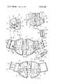
- FIG. 1is a perspective view of a dorsal lumbo sacral support constructed in accordance with my invention and shown positioned on the partial outline of a persons body.
- FIG. 2is a rear view showing the functioning of its pulley system.
- FIGS. 3 and 4are outside and inside plan views.
- FIG. 5is a fragmentary perspective view of the adjustment belts.
- FIG. 6is a perspective view of a buckle as seen removed from its strap.
- the numeral 10refers to my combined support for the dorsal, lumbar and sacrum of a persons body.
- panels 11 and 12consisting of a pair of panels 11 and 12, each being of somewhat the same shape and size being widest at the inner end portions that engage the back of the person using my support and tapering to a lesser width which lies across the stomach of the person.
- the panels 11 and 12 that are fabricated of double layered white brocadeare hemmed along their outer edges and are connected at the end portions to elastic side panels 15 and 16 that conform to and engage firmly the thoracic and pelvic areas of the person about whom the support 10 is positioned.
- each of the outer edges of the panels 1 1 and 12Attached to each of the outer edges of the panels 1 1 and 12 are the pairs of elastic side panels 15 and 16 which overlap with each other and are positioned so that their elastic threads of one panel extend at about 60angle with the other of the pair of panels .15 and 16.
- the reason for this constructionis to cause the outer edges of the back support 10 to spread in a direction away from the main body of the support 10 as a force is applied thereon as is explained hereinafter, causing the back support to be smooth without wrinkles whereby each portion of the back support 10 bears smoothly and evenly against the body of the user.
- Secured to each of the pairs of panels 15, 16are the panels 17 and 18 that carry the fastening devices which consist of hooks 20 and buckles 21 of which there are three in number of each type.
- the hooks 20are fastened symmetrically along the width of the panel 18 by means of short lengths of tape 22 which are folded on themselves to form loops with their ends sewn to the narrow band 23 that is in turn sewn across the width of the panel 18 while a portion of panel 18 extends beyond the position of the hooks 20 protect against the hooks 20 bearing against the users body when the device 10 is in place about the persons body.
- each of the straps 24there is a plurality (three in number) of straps or tapes 24 sewn at one end to the panel 17 and extending outwardly in alignment with the hooks 20.
- the buckle 21Slidably positioned on each of the straps 24 is the buckle 21 that are each adapted to engage the hooks 20 when the support 10 is placed about the persons body in preparation of placing the support tightly and securely about his body as is explained he reinafter.
- the buckles 21are conventional in construction consisting of a rod 26 formed into a somewhat 3 rectangular shape with the ends joined together by a crimped tubing 27 that receives the ends of the rod.
- the other edge portion 25is flattened and given a toothed shape to form a tape gripping edge portion.
- a slide bar 28 that is slidably mounted along the side portions of the rod 26permits the tape 24 to be threaded therethrough as shown best by FIG. 5.
- the free end of tape 24is first passed through the space between the tubing 27 and the slide bar 28, passing over the latter to be folded on itself and returned between the slide bar 28 and edge portion 25 to be beneath the main body portion of the tape 24.
- the buckle 21is now positioned with the toothed edge portion 25 free of the tape 24 and adapted to be engaged by the hook 20.
- the pulling force applied by the hook 20 on the tape 24causes the slide bar 28 to slide in the direction of the toothed edge portion 25 and grip the tape 24 tightly so that it cannot slip or slide through the buckle 21.
- the supportis provided with a pulley system -P- for tightening the support 10 to the desired degree with little effort and which distributes the supporting force equally about the persons body as best shown by FIGS. 1 and 2.
- a pulley system -P-for tightening the support 10 to the desired degree with little effort and which distributes the supporting force equally about the persons body as best shown by FIGS. 1 and 2.
- the tape 31has its ends sewn to the panel 12 adjacent the outer edges of the panel 12, while the ends of the tape 30 are sewn to the panel 11 closer to the mid-portion of the inner edge thereof.
- a metal loop 32 fastened to one end of an elastic tape 33is slidably positioned over the tape 31 and has a hook 34 secured to the other end.
- the other tape 30is provided with a slidable loop 29 that is sewn to the end of an inelastic tape 35 at whose other or free end portion is a buckle 36 identical in construction to the buckles 21 as described herein above.
- a further loop 37is slidably mounted on the tape 35 for the purpose of receiving the free end of the tape 35 beneath the mainbody of the tape 35 thereby locking the 35 against sliding movement in the buckle 36.
- buckles 21can be individually adjusted to permit they support to fit properly about the persons body. Then the person grasps the tapes 33 and 35 at their free ends and brings them around to the front of the support 10. He then draws tightly on these tapes 33 and 35 until he has the support engaging his torso at the desired degree of tightness. He will slide the buckle 36 along the tape 35 until he is able to secure it to the hook 34 thereby maintaining the support 10 about the body at the preselected amount of support being imparted to the persons body.
- the free end of the tape 35will be threaded through the loop 37 to maintain the support 10 at the desired setting of tightness about his body, which setting will remain the same no matter how often the support 10 is removed and replaced on the body unless the person decides to effect a change in degree of support.
- the ends of the tapes 33 and 35 and the panels 17 and 18are provided with conventional mating fibrous entanglement fasteners 38 such as the Velcro type.
- the support 10is normally placed loosely about the persons body upon the hooks 20 being engaged by the buckles 21. Then a simple pull on the tapes 33 and. 35 will draw the two halves of support 10 together evenly and smoothly rendering total alignment and proper adjustment to the persons back.
- the steel bars 14provide the back with the proper upright support force being required and the two pairs of elastic side panels 15, -16 will automatically conform to the thoracic and pelvic areas of the user.
- a support for a persons backcomprising a pair of panel members adapted to be fitted about a persons torso at the position of his back, a plurality of fastening members mounted along one edge portion of each of said panel members for securing said panels at the front portion of the torso, a pair of loops mounted on the other edges of each of said panels, said loops of one of said panels being positioned in proximity of a top and bottom edge portion of said panel and substantially equidistant from a longitudinal center line of said panels, said loops of the other of said panels being positioned in proximity of said mid-portion of said panel and substantially equidistant from said longitudinal center line of said panels, a pair of elongated tape members having end portions, said end portions of one of said pair of elongated tape members being secured to said loops positioned in proximity of said top and bottom edge portions, said end portions of the other of said pair of elongated tape members being secured to said loops positioned in proximity of said mid-portion of said panel, a second pair
Landscapes
- Health & Medical Sciences (AREA)
- Nursing (AREA)
- Orthopedic Medicine & Surgery (AREA)
- Engineering & Computer Science (AREA)
- Biomedical Technology (AREA)
- Heart & Thoracic Surgery (AREA)
- Vascular Medicine (AREA)
- Life Sciences & Earth Sciences (AREA)
- Animal Behavior & Ethology (AREA)
- General Health & Medical Sciences (AREA)
- Public Health (AREA)
- Veterinary Medicine (AREA)
- Orthopedics, Nursing, And Contraception (AREA)
Abstract
Description
Claims (3)
Priority Applications (1)
| Application Number | Priority Date | Filing Date | Title |
|---|---|---|---|
| US527884AUS3926183A (en) | 1974-11-27 | 1974-11-27 | Dorsal lumbo sacral support |
Applications Claiming Priority (1)
| Application Number | Priority Date | Filing Date | Title |
|---|---|---|---|
| US527884AUS3926183A (en) | 1974-11-27 | 1974-11-27 | Dorsal lumbo sacral support |
Publications (1)
| Publication Number | Publication Date |
|---|---|
| US3926183Atrue US3926183A (en) | 1975-12-16 |
Family
ID=24103345
Family Applications (1)
| Application Number | Title | Priority Date | Filing Date |
|---|---|---|---|
| US527884AExpired - LifetimeUS3926183A (en) | 1974-11-27 | 1974-11-27 | Dorsal lumbo sacral support |
Country Status (1)
| Country | Link |
|---|---|
| US (1) | US3926183A (en) |
Cited By (40)
| Publication number | Priority date | Publication date | Assignee | Title |
|---|---|---|---|---|
| US4004579A (en)* | 1975-10-08 | 1977-01-25 | Dedo Richard G | Respiratory assist device |
| US4175553A (en)* | 1977-12-09 | 1979-11-27 | Camp International, Inc. | Lumbosacral-orthosis orthopedic support |
| US4285336A (en)* | 1979-10-23 | 1981-08-25 | Orthomedics, Inc. | Scoliosis orthotic system |
| USD265853S (en) | 1980-01-24 | 1982-08-17 | Camp International, Inc. | Orthopedic garment |
| US4696291A (en)* | 1986-03-06 | 1987-09-29 | Tyo James H | Pelvic stabilization device |
| US4745911A (en)* | 1986-08-06 | 1988-05-24 | Bender Mark R | Support device for weightlifting |
| US4794916A (en)* | 1986-11-20 | 1989-01-03 | Porterfield James A | Lumbar stabilizer |
| US4884562A (en)* | 1985-06-03 | 1989-12-05 | Stone Mario M | Suspension brace assembly |
| US4930499A (en)* | 1989-02-16 | 1990-06-05 | Rowe Daniel G | Sacral brace |
| US4960112A (en)* | 1989-08-21 | 1990-10-02 | Anderegg Linda S | Breast binder for suppression of postpartum lactation |
| US5033460A (en)* | 1986-10-24 | 1991-07-23 | Regents Of The University Of Minnesota | Gravity lumbar traction device and treatment method |
| US5086759A (en)* | 1990-04-10 | 1992-02-11 | Buddingh C Curtis | Chiropractic belt |
| US5188586A (en)* | 1991-10-04 | 1993-02-23 | The Smith Truss Company | Back support belt |
| DE4337354A1 (en)* | 1992-11-04 | 1994-05-05 | Alcare Co Ltd | Lumbago bandage |
| US5634891A (en)* | 1995-04-14 | 1997-06-03 | Peach, U.S., Inc. | Orthotic apparatus useful for treating pain associated with spinal disorders |
| US5762619A (en)* | 1996-12-09 | 1998-06-09 | Simon; William H. | Fashion belt with built-in lumbar support |
| US5853378A (en)* | 1997-10-02 | 1998-12-29 | Modglin; Michael D. | Lumbo-Sacral orthosis |
| US6125851A (en)* | 1994-08-12 | 2000-10-03 | Walker; Brock M. | Spinal support system for seating |
| DE10029447A1 (en)* | 2000-02-23 | 2001-08-30 | Boesl Medizintechnik Gmbh | Girdle type collar for placing round the hips, arms or legs has fastening with adjustment, chambers, and chamber partitions |
| US20030050585A1 (en)* | 2000-03-09 | 2003-03-13 | Modglin Michael D. | Thoraco-lumbo-sacral orthosis |
| US6666838B2 (en) | 2002-04-22 | 2003-12-23 | Deroyal Industries, Inc. | Low-profile lumbo-sacral orthosis |
| US20040139974A1 (en)* | 2000-12-05 | 2004-07-22 | Schwenn Shannon R. | Modular orthosis closure system and method |
| US20070232974A1 (en)* | 2006-04-04 | 2007-10-04 | Serola Richard J | Sacroiliac belt and composite structure |
| US20080004557A1 (en)* | 2006-06-30 | 2008-01-03 | Wolanske Walter J | Equalizing lumbar orthosis |
| US20080221525A1 (en)* | 2007-03-07 | 2008-09-11 | Raul Manzano-Rivera | Gastrostomy garment |
| US20080300522A1 (en)* | 2007-06-01 | 2008-12-04 | Charlene Chen | Abdominal belt |
| US20100228170A1 (en)* | 2009-03-09 | 2010-09-09 | Daiya Industry Co., Ltd. | Lower back supporter |
| GB2483329A (en)* | 2010-08-31 | 2012-03-07 | Innoveering Ltd | Orthopaedic corset with replaceable panels |
| US8328742B2 (en) | 2009-09-25 | 2012-12-11 | Medical Technology Inc. | Adjustable orthopedic back brace |
| WO2012113823A3 (en)* | 2011-02-25 | 2013-02-21 | Bauerfeind Ag | Back or pelvic belt |
| US8398170B2 (en) | 2006-10-06 | 2013-03-19 | Brock Walker | Active response seating system |
| US8808213B2 (en) | 2010-05-28 | 2014-08-19 | Hendricks Orthotic Prosthetic Enterprises, Inc. | Mechanically advantaged spinal system and method |
| US20140288474A1 (en)* | 2011-12-09 | 2014-09-25 | Kowa Company, Ltd. | Supporter |
| US8905957B1 (en) | 2008-08-28 | 2014-12-09 | David J. Kozersky | Adjustable orthotic brace |
| CN107106335A (en)* | 2015-01-08 | 2017-08-29 | 达医雅工业股份有限公司 | Waistband |
| WO2019133762A1 (en)* | 2017-12-27 | 2019-07-04 | Amazing Brace, Llc | Methods and devices for reducing pregnancy-related and post-natal lower back pain |
| US10758051B2 (en) | 2017-07-28 | 2020-09-01 | Inter-Face Medical Llc | Lower back and posture support device |
| US11324622B1 (en) | 2019-08-08 | 2022-05-10 | Preferred Prescription, Inc. | Back brace belt and apparatus, and method of belt length adjustment therefor |
| US11529251B2 (en) | 2014-03-07 | 2022-12-20 | Fiji Manufacturing, Llc | Brace having elastic and inelastic portions |
| DE102012011718B4 (en) | 2012-06-14 | 2024-08-08 | Ormed Gmbh | Back orthosis |
Citations (6)
| Publication number | Priority date | Publication date | Assignee | Title |
|---|---|---|---|---|
| US2100964A (en)* | 1936-02-04 | 1937-11-30 | James R Kendrick Co Inc | Surgical belt |
| US2104699A (en)* | 1936-08-03 | 1938-01-04 | Avery Jenkins N | Surgical appliance |
| US2117309A (en)* | 1936-10-20 | 1938-05-17 | Lewis A Fritsch | Belt support |
| US2219475A (en)* | 1938-04-20 | 1940-10-29 | Charles J Flaherty | Sacroiliac supporter |
| US2476029A (en)* | 1946-09-28 | 1949-07-12 | S H Camp & Company | Adjustment strap for surgical garments and the like |
| US3441027A (en)* | 1968-07-18 | 1969-04-29 | Ira S Lehman | Compound support |
- 1974
- 1974-11-27USUS527884Apatent/US3926183A/ennot_activeExpired - Lifetime
Patent Citations (6)
| Publication number | Priority date | Publication date | Assignee | Title |
|---|---|---|---|---|
| US2100964A (en)* | 1936-02-04 | 1937-11-30 | James R Kendrick Co Inc | Surgical belt |
| US2104699A (en)* | 1936-08-03 | 1938-01-04 | Avery Jenkins N | Surgical appliance |
| US2117309A (en)* | 1936-10-20 | 1938-05-17 | Lewis A Fritsch | Belt support |
| US2219475A (en)* | 1938-04-20 | 1940-10-29 | Charles J Flaherty | Sacroiliac supporter |
| US2476029A (en)* | 1946-09-28 | 1949-07-12 | S H Camp & Company | Adjustment strap for surgical garments and the like |
| US3441027A (en)* | 1968-07-18 | 1969-04-29 | Ira S Lehman | Compound support |
Cited By (59)
| Publication number | Priority date | Publication date | Assignee | Title |
|---|---|---|---|---|
| US4004579A (en)* | 1975-10-08 | 1977-01-25 | Dedo Richard G | Respiratory assist device |
| US4175553A (en)* | 1977-12-09 | 1979-11-27 | Camp International, Inc. | Lumbosacral-orthosis orthopedic support |
| US4285336A (en)* | 1979-10-23 | 1981-08-25 | Orthomedics, Inc. | Scoliosis orthotic system |
| USD265853S (en) | 1980-01-24 | 1982-08-17 | Camp International, Inc. | Orthopedic garment |
| US4884562A (en)* | 1985-06-03 | 1989-12-05 | Stone Mario M | Suspension brace assembly |
| US4696291A (en)* | 1986-03-06 | 1987-09-29 | Tyo James H | Pelvic stabilization device |
| US4745911A (en)* | 1986-08-06 | 1988-05-24 | Bender Mark R | Support device for weightlifting |
| US5033460A (en)* | 1986-10-24 | 1991-07-23 | Regents Of The University Of Minnesota | Gravity lumbar traction device and treatment method |
| US4794916A (en)* | 1986-11-20 | 1989-01-03 | Porterfield James A | Lumbar stabilizer |
| US4930499A (en)* | 1989-02-16 | 1990-06-05 | Rowe Daniel G | Sacral brace |
| US4960112A (en)* | 1989-08-21 | 1990-10-02 | Anderegg Linda S | Breast binder for suppression of postpartum lactation |
| US5086759A (en)* | 1990-04-10 | 1992-02-11 | Buddingh C Curtis | Chiropractic belt |
| US5188586A (en)* | 1991-10-04 | 1993-02-23 | The Smith Truss Company | Back support belt |
| US6068606A (en)* | 1991-10-04 | 2000-05-30 | The Smith Truss Company | Back support belt |
| DE4337354A1 (en)* | 1992-11-04 | 1994-05-05 | Alcare Co Ltd | Lumbago bandage |
| JP3370709B2 (en) | 1992-11-04 | 2003-01-27 | アルケア株式会社 | Backache belt |
| US6532962B1 (en) | 1994-08-12 | 2003-03-18 | Brock M. Walker | Spinal support system for seating |
| US6125851A (en)* | 1994-08-12 | 2000-10-03 | Walker; Brock M. | Spinal support system for seating |
| US5634891A (en)* | 1995-04-14 | 1997-06-03 | Peach, U.S., Inc. | Orthotic apparatus useful for treating pain associated with spinal disorders |
| US5762619A (en)* | 1996-12-09 | 1998-06-09 | Simon; William H. | Fashion belt with built-in lumbar support |
| WO1999017687A1 (en) | 1997-10-02 | 1999-04-15 | Modglin Michael D | Lumbo-sacral orthosis |
| US5967998A (en)* | 1997-10-02 | 1999-10-19 | Modglin; Michael D. | Lumbo-sacral orthosis |
| US5853378A (en)* | 1997-10-02 | 1998-12-29 | Modglin; Michael D. | Lumbo-Sacral orthosis |
| DE10029447A1 (en)* | 2000-02-23 | 2001-08-30 | Boesl Medizintechnik Gmbh | Girdle type collar for placing round the hips, arms or legs has fastening with adjustment, chambers, and chamber partitions |
| US20030050585A1 (en)* | 2000-03-09 | 2003-03-13 | Modglin Michael D. | Thoraco-lumbo-sacral orthosis |
| US20040139974A1 (en)* | 2000-12-05 | 2004-07-22 | Schwenn Shannon R. | Modular orthosis closure system and method |
| US7186229B2 (en)* | 2000-12-05 | 2007-03-06 | Orthomerica Products, Inc. | Modular orthosis closure system and method |
| US6666838B2 (en) | 2002-04-22 | 2003-12-23 | Deroyal Industries, Inc. | Low-profile lumbo-sacral orthosis |
| US20070232974A1 (en)* | 2006-04-04 | 2007-10-04 | Serola Richard J | Sacroiliac belt and composite structure |
| US9675492B2 (en) | 2006-04-04 | 2017-06-13 | Richard J. Serola | Sacroiliac belt and composite structure |
| US9326883B2 (en) | 2006-04-04 | 2016-05-03 | Richard J. Serola | Sacroiliac belt and composite structure |
| US20070232973A1 (en)* | 2006-04-04 | 2007-10-04 | Serola Richard J | Sacroiliac belt and composite structure |
| US8591445B2 (en) | 2006-04-04 | 2013-11-26 | Richard J. Serola | Sacroiliac belt and composite structure |
| US20080004557A1 (en)* | 2006-06-30 | 2008-01-03 | Wolanske Walter J | Equalizing lumbar orthosis |
| US7449006B2 (en)* | 2006-06-30 | 2008-11-11 | Wolanske Walter J | Equalizing lumbar orthosis |
| US8398170B2 (en) | 2006-10-06 | 2013-03-19 | Brock Walker | Active response seating system |
| US9675179B2 (en) | 2006-10-06 | 2017-06-13 | Trac Tec, Ltd. | Active response seating system |
| US9049937B2 (en) | 2006-10-06 | 2015-06-09 | Brock Walker | Active response seating system |
| US20080221525A1 (en)* | 2007-03-07 | 2008-09-11 | Raul Manzano-Rivera | Gastrostomy garment |
| US7661152B2 (en)* | 2007-03-07 | 2010-02-16 | Raul Manzano-Rivera | Gastrostomy garment |
| US20080300522A1 (en)* | 2007-06-01 | 2008-12-04 | Charlene Chen | Abdominal belt |
| US8905957B1 (en) | 2008-08-28 | 2014-12-09 | David J. Kozersky | Adjustable orthotic brace |
| US8057417B2 (en)* | 2009-03-09 | 2011-11-15 | Daiya Industry Co., Ltd. | Lower back supporter |
| US20100228170A1 (en)* | 2009-03-09 | 2010-09-09 | Daiya Industry Co., Ltd. | Lower back supporter |
| US8328742B2 (en) | 2009-09-25 | 2012-12-11 | Medical Technology Inc. | Adjustable orthopedic back brace |
| US8808213B2 (en) | 2010-05-28 | 2014-08-19 | Hendricks Orthotic Prosthetic Enterprises, Inc. | Mechanically advantaged spinal system and method |
| GB2483329A (en)* | 2010-08-31 | 2012-03-07 | Innoveering Ltd | Orthopaedic corset with replaceable panels |
| WO2012113823A3 (en)* | 2011-02-25 | 2013-02-21 | Bauerfeind Ag | Back or pelvic belt |
| US20140288474A1 (en)* | 2011-12-09 | 2014-09-25 | Kowa Company, Ltd. | Supporter |
| US10335306B2 (en)* | 2011-12-09 | 2019-07-02 | Kowa Co., Ltd | Supporter |
| DE102012011718B4 (en) | 2012-06-14 | 2024-08-08 | Ormed Gmbh | Back orthosis |
| US11529251B2 (en) | 2014-03-07 | 2022-12-20 | Fiji Manufacturing, Llc | Brace having elastic and inelastic portions |
| CN107106335A (en)* | 2015-01-08 | 2017-08-29 | 达医雅工业股份有限公司 | Waistband |
| EP3243490A4 (en)* | 2015-01-08 | 2018-09-05 | Daiya Industry Co., Ltd. | Waist belt |
| US10758051B2 (en) | 2017-07-28 | 2020-09-01 | Inter-Face Medical Llc | Lower back and posture support device |
| US11432654B2 (en) | 2017-07-28 | 2022-09-06 | Inter-Face Medical Llc | Lower back and posture support device |
| WO2019133762A1 (en)* | 2017-12-27 | 2019-07-04 | Amazing Brace, Llc | Methods and devices for reducing pregnancy-related and post-natal lower back pain |
| US11324622B1 (en) | 2019-08-08 | 2022-05-10 | Preferred Prescription, Inc. | Back brace belt and apparatus, and method of belt length adjustment therefor |
| US12357490B2 (en) | 2019-08-08 | 2025-07-15 | Preferred Prescription, Inc. | Back brace with enhanced height support and adjustment capability |
Similar Documents
| Publication | Publication Date | Title |
|---|---|---|
| US3926183A (en) | Dorsal lumbo sacral support | |
| US5086758A (en) | Belt support device with adjustable hook and loop-type fastener | |
| US5257419A (en) | Abdominal support belt | |
| US9358415B2 (en) | Spinal therapy device | |
| US4099524A (en) | Sacro-lumbar support belt | |
| US5316022A (en) | Sports belt with cinchable fastener system | |
| US3442270A (en) | Surgical binder | |
| US3968803A (en) | Surgical chest dressing | |
| US6770044B1 (en) | Arm sling | |
| US3554190A (en) | Back, shoulder and stomach support | |
| US5772617A (en) | Stabilizing arm sling | |
| US4396013A (en) | Support and guide strap | |
| US5076288A (en) | Double-lock friction fastener system | |
| CA2607558C (en) | Corset | |
| US20100100019A1 (en) | Abdominal support | |
| US20130237891A1 (en) | Orthotic brace tightening device | |
| CN108785965A (en) | Belt-Based Exercise System | |
| US9545534B2 (en) | Apparatus for using a medicine ball | |
| US5302171A (en) | Back and stomach support device | |
| US4005506A (en) | Adjustable strap assembly | |
| CA2565578C (en) | Hybrid belt assembly | |
| JP2001218779A (en) | Posture correction orthosis for upper body | |
| US4361258A (en) | Adjustable carrying strap | |
| US5762619A (en) | Fashion belt with built-in lumbar support | |
| US2848993A (en) | Restraining device |
Legal Events
| Date | Code | Title | Description |
|---|---|---|---|
| AS | Assignment | Owner name:PROFESSIONAL MEDICAL PRODUCTS INC. 525 NORTH EMERA Free format text:ASSIGNMENT OF ASSIGNORS INTEREST.;ASSIGNOR:ALL ORTHOPEDIC APPLIANCES, INC., A CORP. OF FL;REEL/FRAME:004074/0502 Effective date:19821008 | |
| AS | Assignment | Owner name:GENERAL ELECTRIC CREDIT CORPORATION, ATLANTA, GA., Free format text:SECURITY INTEREST;ASSIGNOR:PROFESSIONAL MEDICAL PRODUCTS, INC.;REEL/FRAME:004110/0213 Effective date:19821008 | |
| STCF | Information on status: patent grant | Free format text:PATENTED FILE - (OLD CASE ADDED FOR FILE TRACKING PURPOSES) | |
| AS | Assignment | Owner name:PROFESSIONAL MEDICAL PRODUCTS, INC., A DE CORP. Free format text:RELEASED BY SECURED PARTY;ASSIGNOR:GENERAL ELECTRIC CAPITAL CORPORATION;REEL/FRAME:004899/0724 Effective date:19880429 | |
| AS | Assignment | Owner name:KIRSCHNER MEDICAL CORPORATION, 10 WEST AYLESBURY R Free format text:ASSIGNMENT OF ASSIGNORS INTEREST.;ASSIGNOR:PROFESSIONAL MEDICAL PRODUCTS, INC.,;REEL/FRAME:004937/0683 Effective date:19880429 | |
| AS | Assignment | Owner name:MARYLAND NATIONAL BANK, MARYLAND Free format text:AMENDMENT TO SECURITY AGREEMENT;ASSIGNOR:KIRSCHNER MEDICAL CORPORATION;REEL/FRAME:006359/0009 Effective date:19920930 |