US3917373A - Coupling ring assembly - Google Patents
Coupling ring assemblyDownload PDFInfo
- Publication number
- US3917373A US3917373AUS476613AUS47661374AUS3917373AUS 3917373 AUS3917373 AUS 3917373AUS 476613 AUS476613 AUS 476613AUS 47661374 AUS47661374 AUS 47661374AUS 3917373 AUS3917373 AUS 3917373A
- Authority
- US
- United States
- Prior art keywords
- ring
- ratchet
- cam
- shell
- face
- Prior art date
- Legal status (The legal status is an assumption and is not a legal conclusion. Google has not performed a legal analysis and makes no representation as to the accuracy of the status listed.)
- Expired - Lifetime
Links
Images
Classifications
- H—ELECTRICITY
- H01—ELECTRIC ELEMENTS
- H01R—ELECTRICALLY-CONDUCTIVE CONNECTIONS; STRUCTURAL ASSOCIATIONS OF A PLURALITY OF MUTUALLY-INSULATED ELECTRICAL CONNECTING ELEMENTS; COUPLING DEVICES; CURRENT COLLECTORS
- H01R13/00—Details of coupling devices of the kinds covered by groups H01R12/70 or H01R24/00 - H01R33/00
- H01R13/62—Means for facilitating engagement or disengagement of coupling parts or for holding them in engagement
- H01R13/621—Bolt, set screw or screw clamp
Definitions
- ABSTRACTThe following specification discloses a coupling assembly for electrical connector apparatus in which a threaded coupling ring rotatably mounted on one shell is threaded onto a second shell to couple the shells for electrically engaging the contacts carried by the shells.
- Each tooth on the flangehas a cam face formed at a small angle to the radial plane of the flange for engagement with a similar cam face on each tooth on the ratchet washer in response to the threading rotation of the ring to cam the ratchet washer from the flange against the spring bias so that resistance to threading rotation is minimized.
- a stop face having a large angle to the respective radial planes of the washer and flangeis also formed on each tooth and the stop faces engage for providing a large resistance to rotation of the coupling ring in the unthreading or loosening direction to prevent inadvertent loosening, but do permit rotation in the loosening direction, if disassembly is desired.
- Electrical connector apparatususually includes a plug shell carrying a plurality of contacts each engageable with a respective contact of a plurality of contacts carried by a receptacle shell.
- a coupling ring rotatably mounted on one shellmay be arranged for threaded engagement with the other shell to move the shells axially of each other and ensure electrical engagement between the respective contacts.
- a flange on the one shellhas a front radial face abutting an internal shoulder of the coupling ring and a rear radial face on the flange engages a wave washer captured between the flange and a retaining ring secured to the rear end of the coupling ring.
- The" ringsare thus capable of limited axial movement relative the one shell against the bias of the wave washer to permit the coupling ring to be threaded on the other shell.
- the biasing force of the spring wave washer acting in an axial directionprovides a force for holding the threads engaged; however, this force is of substantially the same magnitude as the force required to thread the coupling ring on the other shell. Occasionally vibrational or other forces, having a magnitude corresponding to the force holding the threads engaged, are applied to the shells and therefore loosen the coupling ring from the other shell.
- Arrangements for resisting loosening or unthreading forces between connector shellshave incorporated axially extending smoothly curved contoured teeth fixed on a coupling ring and engaging similarly contoured fixed teeth on one connector shell with the ring and its teeth biased toward the mating shell.
- both the coupling ring and the mating shellmust reciprocate axially to permit the rotation and therefore considerable force is required.
- the smooth contourprovides no greater resistance to rotation of the ring in the loosening direction than for tightening.
- teeth having faces which are perpendicular to each direction of rotationhave been employed, but these must be disengaged to permit threading, and after the threading operation is completed, the perpendicular faces on the teeth are re-engaged to prevent loosening. Disassembly is permitted on retraction or disengagement of the engaged perpendicular faces of the teeth from one another against a spring bias. As may be visualized, this arrangement, while it holds the members against loosening and also permits disassembly, is relatively expensive, cumbersome and difficult to operate, since the teeth must be held disengaged while the ring is either tightened or loosened. Other arrangements may incorporate spring detents.
- Such detentscan deform to move past a set of teeth in response to the threading rotation, but disassembly cannot be provided without auxiliary means for disengaging the detents from the teeth.
- springs used in electrical connector coupling assembliesrequire considerable wall thickness and sturdy construction in order to provide the desired spring force and therefore cannot be easily fabricated to provide reliable and durable opera tion or enable facile disengagement in the event disassembly is desired.
- the present inventionavoids the above problems through the simple provision of a ratchet washer keyed to the coupling ring and interposed between the conventional wave washer and the flange on one connector shell.
- the ratcher washerhas axially extending ratchet teeth for nesting engagement between axially extending pawl teeth on the one shell flange with each tooth having a leading or cam face formed at a small angle to a radial plane for enabling facile threading of the coupling ring against the force of the wave washer and a stop face formed at a steep or large angle to the radial plane for strongly resisting rotation in the opposite or unthreading direction.
- Reference to the radial planerefers, of course, to a plane transverse to the axis of the particular part such as the flange, washer, ring or shell.
- the stop faces on the teethwill also compress the wave washer to enable the teeth to move past each other and permit unthreading of the coupling ring in the event disassembly of the connector apparatus is desired.
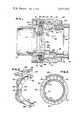
- FIG. 1is a sectional view illustrating an electrical connector coupling assembly utilizing the principles of the present invention
- FIG. 2is an isometric view illustrating a portion of the ratchet washer and coupling ring
- FIG. 3is an end view illustrating the pawl flange with a related portion of the shell and ring in section.
- FIG. 1a coupling assembly is shown for securing one electrical connector shell 12 to a second electrical connector shell 14.
- the shells 12 and 14are generally cylindrical and only a relevant portion of the front end 16 ofa conventional plug shell 12 being shown for telescoping engagement within the front end 18 of receptacle shell 14.
- the front end 16 of shell 12has one or more radially outwardly extending keys such as 20 for engagement in respective keyways 22 located in the internal surface at the front end 18 of shell 14.
- the keys and keywaysserve to properly align the shells ensuring correct engagement between socket contacts, one of which is indicated by broken lines 24 in shell 12 and pin contacts, one of which is indicated by broken lines 26 in shell 14.
- the contacts 24 and 26are secured in conventional dielectric inserts (not shown) in turn secured in the respective shells in accordance with accepted and conventional practice.
- the coupling assembly 10includes a coupling ring 28 having threads 29 formed on the internal surface thereof adjacent the front end of the ring for engagement with threads 30 on the external surface of the front end 18 of shell 14 to axially move the shells toward each other and provide secure electrical engagement between the contacts.
- An enlarged bore 31 formed in the ring 28receives a radially outwardly extending flange 32 formed on'shell 12 intermediate opposite axial ends of shell 12 with the bore having a shoulder 34'for engaging the front radial face of flange 32.
- the flange 32 and shoulder 34limit movement of the ring 28 relative shell 12 in one or a rearward direction.
- the bore 31also receives a ratchet washer 36 having integrally formed axially extending ratchet teeth 38 on the front radial face thereof for engagement with axially extendingpawl teeth 40 integrally formed on the rear radial face of flange 32.
- a spring wave washer 42having a nominal'wall thickness between 0.1 inch and 0.125 inch, depending on the connector shell size, is located in bore 31 to engage the rear radial face of washer 36 and thewashers 36 and 40 are held in bore 31 by a retaining ring 44.
- Retaining ring 44is secured in the rear end of ring 28 by a series of closed annular teeth on the external surface thereof which are force fit past similarly sized and shaped teeth on the internal surface of the rear end of bore 31 to interlock the teeth and secure the rings and washers on the shell 12.
- Axially extending slots or recesses 46are formed in the enlarged diameter surface of rear bore 31 of ring 32 for receiving teeth or keys 48 extending radially outwardly from the periphery of ratchet washer 38 and integrally formed thereon.
- the plurality of keys and keywaysaid in maintaining the angle of the ratchet washer relative the axis of the ring and distribute the load transferred between the ring and washer.
- the ratchet washer 36will therefore rotate with the ring 28 and is biased axially of shell 12 by the wave washer 42 against keyway 46.
- the wave washer 42is assembled in bore.
- the ring 28 and washer 36are thus rotatably mounted or carried by the shell 12 with both capable of limited axial movement of the shell and the washer capable of limited axial movement relative the ring.
- the ratchet teeth 38 and the detent or pawl teeth 40may be formed accurately by investment casting, for
- Teeth 40are provided about the complete periphery of the respective radial face or plane of flange 32 perpendicular to the shell axis, but only four equiangularly spaced teeth 38 are provided on the corresponding radial face or plane of washer 36.
- Each tooth 40 on flange 32has a leading or pawl cam face 50 having a relatively small angle of substantially 30 to the radial face or plane of the flange for engagement with a respective leading or ratchet cam face 52 of similar small angle to the front radial face or plane of washer 36 on each of the four teeth 38.
- the faces 50 and 52enable rotation of the ring 28 under relatively little additional force in one direction of rotation of the coupling ring 28 and washer 42 for threading ring 28 on shell 14, since the teeth faces 50 and 52 act as cams or as cam means and cam follower means to compress the spring wave washer 42 against its bias.
- the key meansenables relative axial movement of the teeth for automatic disengagement against the bias of spring 42 so that the teeth may move past each other during rotation of ring 28 in the threading direction.
- the engaged teethhold or resist rotation of the ring until a predetermined force or torque is applied to the coupling ring for threading it on the mating shell'whereupon the cam faces automatically move the teeth independentlyjof the shell and ring to disengage the ratchet teeth and washer from the pawl teeth and flange.
- the detent or stop meansengage to prevent rotation in the loosening or opposite direction unless a substantially greater force is applied to loosen the rings than the force required to couple the rings.
- each pawl tooth 40is inclined at a relatively large or'steep angle of substantially 60 to the radial face of flange 32 for engagement with a detent or ratchet stop face 56 on each ratchet tooth 38 of washer 36 and arranged at a similar steep angle to the washer radial plane or face to resist rotation in the opposite direction between the flange and washer and thereby'prevent loosening of the coupling assembly 10 from shell 14.
- substantially twice the forceis required to loosen the threads 29 and 30 as is required to thread the same, since the difference between the threading and unthreading forces is related to the'difference between the angles of the cam and stop faces.
- the ring 28receives the flange 32 in bore 31 in abutment with shoulder 34. Then the washer 36 is assembled in the bore 31 with key 48 located in the slot or 31 followed by the assembly of retaining ring 44 so that the coupling assembly is retained on shell 12 with the teeth 38 biased axially by the washer 42 for engagement between teeth 40.
- the front end 16 of shell 12is telescoped in the front end 18 of shell 14 with the key 20 engaged in keyway 22 to angularly align the contacts 24 and 26.
- the thread 29 on coupling ring 28is engaged with the thread 30 on shell 14 and the coupling ring 28 rotated in a threading or one direction in response to the application of a predetermined force to move the front ends of the shells toward each other as indicated by dashed lines 58 for coupling the shells.
- Rotation of the ring 28rotates the ratchet washer 36 since the washer 36 is keyed to ring 28 by the key means 46 and 48.
- each ratchet washer tooth 38moves past respective cam faces 50 on the pawl teeth 40 against the bias of wavewasher 42 by compressing the spring or wave washer enough to enable axial displacement corresponding to the height of the teeth.
- the reverse or stop faces 54will act as pawls or detents in cooperation with stop faces 56 to prevent rotation in the opposite or unthreading direction despite the application of a second force substantially greater than the force required to thread the ring onto shell 14.
- the shells l2 and 14are now held securely against vibration and other forces tending to loosen the coupling ring.
- stop faces 54 and 56will also act as cam means and cam follower means and move past each other against the bias or pressure of the spring wave washer 42; however, the force required for this movement in the opposite or uncoupling direction is substantially greater than that required for rotation in the direction for coupling the shells or the second force resulting from ambient conditions.
- a coupling ring with threadsrotatably carried on said one shell and rotatable in one direction for engaging the threads on said ring with the threads on the other shell to couple the shells
- first cam meansrotatable with said coupling ring
- each cam meansfor automatically disengaging one of the cam means from the other of the cam means only in response to the application of another force greater than said one predetermined force to said ring and cam means for rotating said ring in a direction opposite said one direction to thereby uncouple said shells.
- a retaining ringengaging said spring and having a plurality of closed annular teeth, and a plurality of closed annular teeth on said coupling ring having substantially the same diameter as the closed annular teeth on said retaining ring with the teeth on said retaining ring force fit past the teeth on said coupling ring to interlock said teeth for securing said retaining ring to said coupling ring.
- said second cam meansincludes a flange fixed to said one shell, and a plurality of pawl teeth each having a cam face and located on said flange.
- said first cam meansincludes a ratchet washer, and a plurality of ratchet teeth each having a cam face and located on said ratchet washer.
- a coupling assemblyfor coupling one electrical connector shell with another shell having threads
- a coupling ring with threadsrotatably carried on said one shell and rotatable in one direction for engaging the threads on said ring with the threads on the other shell to couple the shells
- first cam meansrotatable with said coupling ring
- said means for engaging said first cam means with said second cam meansincluding a spring
- said means for automatically disengaging the one cam means from the other cam meansincluding means keying the one cam means to said ring for movement axially of said ring against the bias of said spring,
- said keying means for automatically disengaging the one cam means from the other cam meansalso enables the disengagement of said one additional cam means from the other additional cam means independently of said ring against the bias of said spring in response to the application of a third force in said opposite direction to said ring greater than said second force in said oppositedirection to rotate said ring in said opposite direction for uncoupling said shells.
- a coupling assemblyfor coupling one electrical connector shellwith another shell having threads
- a coupling ring with threadsrotatably carried on said one shell and rotatable in one direction for engaging the threads on said ring with the threads on the other shell to couple the shells
- first cam meansrotatable with said coupling ring
- said engaged cam meansfor automatically disengaging one of the cam means independently of said ring and one shell from the other of the cam means without deformation of said cam means in response to the application of a predetermined force to said ring and cam means for rotating said ring in one direction to thereby engage the threads on said ring with the threads on the other shell to couple the shells
- said second cam meansincluding a flange fixed to said one shell, and a plurality of pawl teeth each having a cam face and located on said flange
- said first cam meansincluding a ratchet washer, and a pluralityof ratchet teeth each having a cam face and located on said ratchet washer,
- said means for engaging the cam meanscomprising a spring on said one shell for biasing said washer including the'cam faces on the ratchet teeth into engagement with the cam faces on the pawl teeth,
- said means for automatically disengaging the engaged cam facesincluding means keying said ratchet washer to said ring for movement axially of said ring whereby a cam face on each ratchet tooth engaging with each cam face on a respective pawl tooth moves said washer against the bias of said spring in response to the application of said predetermined force to said ring in said one direction to disengage said ratchet teeth from said pawl teeth, and
- each cam facehaving one angle to a radial plane and each stop face having a greater angle to said radial plane whereby a substantially greater force is required to rotate said ring in said opposite direction than the force required for rotating said ring in said one direction.
- a coupling assembly for use with electrical connector apparatusincluding a first shell carrying a threaded rotatable coupling ring and a plurality of electrical contacts each adapted to engage a respective electrical contact of a second plurality of contacts carried by a second shell having threads for engagement with said threaded coupling ring to couple the shells to each other in response to the rotation of said coupling ring in one direction, the improvement comprising:-
- a first ratchet cam face and a first ratchet stop facerotatable with said coupling ring with said ratchet cam face located for engaging with the pawl cam face in response to rotation of said ring and ratchet cam face in one direction and the ratchet stop face located for engaging with the pawl stop face in response to rotation of said ring and ratchet stop face in the opposite direction;
- each ratchet faceand means for biasing and moving each ratchet face relative to each pawl face independently of said ring whereby the engagement of the ratchet cam facewith the pawl cam face in response to the application of one force to said ring for rotating said ring and the ratchet cam face in said one direction enables one of said cam faces to move against the bias of said means for disengaging the cam faces to enable the threading of said coupling ring on said second shell and the engagement of said contacts whereafter the engagement of the ratchet stop face with the pawl stop face prevents rotation of the ratchet faces and coupling ring in response to-the application in the opposite direction of a force greater than said oneforce.
- a ratchet washerwith a plurality of ratchet teeth on said ratchet washer, one tooth having said first ratchet cam face and said first ratchet stop face and each other tooth having a ratchet cam face and a ratchet stop face corresponding to the first ratchet cam face and first ratchet stop face respectively.
- said means for biasing and movingincludes a wave washer engaged between said ratchet washer and said coupling ring, and means keying said ratchet washer for rotation with said coupling ring and for movement of said washer axially relative said ring.
- a flangeextending radially outwardly of said first shell and secured to said first shell with a plurality of pawl teeth on said flange, one pawl tooth having said first pawl cam face and said first pawl stop face and each other pawl tooth having a pawl cam face and a pawl stop face corresponding to the first pawl cam face and first pawl stop face respectively.
- each ratchet toothis formed on the front radial face of said washer and each pawl tooth is formed on the rear radial face of said flange and the cam faces extend axially at an angle of substantially 30 to the respective radial face of said washer and flange, and said stop faces extend axially at an angle of substantially 60 to the re spective radial face of said washer and flange whereby rotation of said washer and ring in said opposite direction is provided in response to the application of a force to said ring in said opposite direction of substantially twice said one force.
- a plurality of ratchet cam faces, a plurality of ratchet stop faces, a plurality of pawl cam faces and a plurality of pawl stop facessaid cam faces extending axially from a respective radial plane at a relatively small angle and said stop faces extending axially from the respective radial plane at a second angle greater than said small angle whereby rotation of said coupling ring in said opposite direction is enabled in response to the application of a force greater than said one force by an amount corresponding to the difference in said small angle and said second angle.
- a coupling assembly for use with electrical connector apparatusincluding a first shell carrying a plurality of electrical contacts each adapted to engage a respective electrical contact of a second plurality of contacts carried by a second shell having a threaded periphery, the improvement comprising:
- each toothhaving a cam face and a stop face
- each ratchet toothhaving a cam face for engagement with a cam face of each pawl tooth and a stop face for engagement with a stop face on each pawl tooth;
- a coupling ringrotatably carried on said first shell and having threads for engaging the threaded periphery of said second shell to secure said second shell to said first shell in response to the rotation of said coupling ring in one direction;
- a coupling assembly for use with electrical connector apparatusincluding a flrst shell carrying a plurality of electrical contacts each adapted to engage a respective electrical contact of a second plurality of contacts carried by a second shell having a threaded periphery, the improvement comprising:
- each pawl toothintegrally formed on said flange and extending axially rearwardly of said first shell with each pawl tooth having a cam face extending at a relatively small angle from a radial plane of said flange and a stop face extending at a relatively large angle to said radial plane;
- a ratchet washerhaving a plurality of axially extending ratchet teeth integrally formed on said washer for engagement between the pawl teeth with the ratchet teeth each having a cam face extending at said relatively small angle to a radial plane of said ratchet washer for engaging a cam face on a pawl tooth and a stop face on each ratchet tooth extending at said large angle to a radial plane of said ratchet washer for engaging a stop face of a pawl tooth;
- coupling ringrotatably carried on said first shell and having threads for engaging the threaded periphery of the second shell to secure said second shell to said first shell in response to rotation of said coupling ring in one direction with each contact carried by said first shell engaged with a respective contact carried by said second shell;
Landscapes
- Details Of Connecting Devices For Male And Female Coupling (AREA)
- Quick-Acting Or Multi-Walled Pipe Joints (AREA)
- Other Liquid Machine Or Engine Such As Wave Power Use (AREA)
- Medical Preparation Storing Or Oral Administration Devices (AREA)
- Orthopedics, Nursing, And Contraception (AREA)
- Dental Prosthetics (AREA)
Abstract
Description
Claims (22)
Priority Applications (6)
| Application Number | Priority Date | Filing Date | Title |
|---|---|---|---|
| US476613AUS3917373A (en) | 1974-06-05 | 1974-06-05 | Coupling ring assembly |
| GB15388/75AGB1510861A (en) | 1974-06-05 | 1975-04-15 | Coupling ring assembly |
| CA225,310ACA1046150A (en) | 1974-06-05 | 1975-04-23 | Coupling ring assembly |
| DE19752518563DE2518563A1 (en) | 1974-06-05 | 1975-04-25 | CONNECTOR COUPLING |
| FR7513082AFR2274146A1 (en) | 1974-06-05 | 1975-04-25 | ELECTRICAL CONNECTOR DEVICE |
| JP50050880AJPS50158892A (en) | 1974-06-05 | 1975-04-28 |
Applications Claiming Priority (1)
| Application Number | Priority Date | Filing Date | Title |
|---|---|---|---|
| US476613AUS3917373A (en) | 1974-06-05 | 1974-06-05 | Coupling ring assembly |
Publications (1)
| Publication Number | Publication Date |
|---|---|
| US3917373Atrue US3917373A (en) | 1975-11-04 |
Family
ID=23892557
Family Applications (1)
| Application Number | Title | Priority Date | Filing Date |
|---|---|---|---|
| US476613AExpired - LifetimeUS3917373A (en) | 1974-06-05 | 1974-06-05 | Coupling ring assembly |
Country Status (6)
| Country | Link |
|---|---|
| US (1) | US3917373A (en) |
| JP (1) | JPS50158892A (en) |
| CA (1) | CA1046150A (en) |
| DE (1) | DE2518563A1 (en) |
| FR (1) | FR2274146A1 (en) |
| GB (1) | GB1510861A (en) |
Cited By (65)
| Publication number | Priority date | Publication date | Assignee | Title |
|---|---|---|---|---|
| DE2733517A1 (en)* | 1976-07-26 | 1978-02-02 | Automation Ind Inc | ELECTRIC CONNECTOR |
| US4168105A (en)* | 1978-06-27 | 1979-09-18 | Amp Incorporated | Resiliently loaded coupling ring |
| FR2448794A1 (en)* | 1979-02-06 | 1980-09-05 | Bunker Ramo | ELECTRICAL CONNECTOR IN TWO PARTS COUPLED BY SCREWING |
| US4235498A (en)* | 1979-07-26 | 1980-11-25 | The Bendix Corporation | Electrical connector with locking means |
| US4239314A (en)* | 1979-04-11 | 1980-12-16 | Bunker Ramo Corporation | Electrical connector |
| FR2494507A1 (en)* | 1980-11-14 | 1982-05-21 | Bendix Corp | ELECTRICAL CONNECTOR ELEMENT IN PLASTIC MATERIAL |
| EP0052535A1 (en)* | 1980-11-14 | 1982-05-26 | The Bendix Corporation | Electrical connector housing with integral retention mechanism |
| EP0052530A1 (en)* | 1980-11-14 | 1982-05-26 | The Bendix Corporation | Electrical connector coupling ring having an integral spring |
| EP0052971A3 (en)* | 1980-11-24 | 1982-06-30 | T.J. Electronics, Inc. | Self-locking coupling nut for electrical connectors |
| FR2541522A1 (en)* | 1983-02-18 | 1984-08-24 | Drogo Pierre | Electrical connector |
| US4487470A (en)* | 1983-05-11 | 1984-12-11 | The Bendix Corporation | Anti-decoupling mechanism for an electrical connector assembly |
| FR2549303A2 (en)* | 1983-02-18 | 1985-01-18 | Drogo Pierre | ELECTRICAL CONNECTOR |
| US4494810A (en)* | 1983-05-11 | 1985-01-22 | The Bendix Corporation | Anti-decoupling device for an electrical connector |
| US4508408A (en)* | 1983-05-11 | 1985-04-02 | Allied Corporation | Anti-decoupling mechanism for an electrical connector assembly |
| US4525017A (en)* | 1983-05-11 | 1985-06-25 | Allied Corporation | Anti-decoupling mechanism for an electrical connector assembly |
| US4531802A (en)* | 1984-04-27 | 1985-07-30 | Allied Corporation | Electrical connector assembly having locking means |
| US4536048A (en)* | 1983-05-11 | 1985-08-20 | Allied Corporation | Anti-decoupling mechanism for an electrical connector assembly |
| US4542952A (en)* | 1984-04-27 | 1985-09-24 | Allied Corporation | Electrical connector assembly having locking means |
| US4552427A (en)* | 1982-12-13 | 1985-11-12 | International Telephone & Telegraph Corp. | Self-locking connector |
| US4588246A (en)* | 1983-05-11 | 1986-05-13 | Allied Corporation | Anti-decoupling mechanism for an electrical connector assembly |
| US4639064A (en)* | 1986-02-28 | 1987-01-27 | Allied Corporation | Anti-decoupling resisting and EMI shielding means for an electrical connector assembly |
| FR2587144A1 (en)* | 1985-09-06 | 1987-03-13 | Drogo Pierre | MULTI-PIN ELECTRICAL CONNECTOR |
| EP0218060A1 (en)* | 1985-09-13 | 1987-04-15 | Socapex S.A. | Electrical connector with anti-decoupling device |
| US4703988A (en)* | 1985-08-12 | 1987-11-03 | Souriau Et Cie | Self-locking electric connector |
| US4741706A (en)* | 1986-03-06 | 1988-05-03 | Daiichi Denshi Kogyo Kabushiki Kaisha | Locked connector |
| US4820185A (en)* | 1988-01-20 | 1989-04-11 | Hughes Aircraft Company | Anti-backlash automatic locking connector coupling mechanism |
| US4838805A (en)* | 1984-01-05 | 1989-06-13 | Raytheon Company | Connector engaging nut locking mechanism |
| EP0381582A1 (en)* | 1989-02-03 | 1990-08-08 | Pierre Drogo | Electrical connector |
| US5082454A (en)* | 1989-09-28 | 1992-01-21 | Joslyn Corporation | Two-piece retaining ring |
| US5199894A (en)* | 1990-12-14 | 1993-04-06 | Kalny Lou E | Self-locking connector |
| US5203477A (en)* | 1990-06-30 | 1993-04-20 | Yin Seng Lim | Closure unit for kegs |
| US5246379A (en)* | 1992-03-02 | 1993-09-21 | Simmonds Precision Engine Systems, Inc. | Electrical connector and backshell assembly |
| US5295866A (en)* | 1990-10-09 | 1994-03-22 | Kroger Roy E | Insert retention gas tight seal for electrical connector and method of making same |
| FR2696049A1 (en)* | 1992-09-21 | 1994-03-25 | Souriau & Cie | Electrical connector with threaded ring and preponderance lock. |
| US5447447A (en)* | 1992-11-10 | 1995-09-05 | Woodhead Industries, Inc. | Vibration resistant electrical coupling with tactile indication |
| WO1996023332A1 (en)* | 1995-01-25 | 1996-08-01 | Amphenol Corporation | Anti-decoupling device |
| US5580278A (en)* | 1994-10-04 | 1996-12-03 | Glenair, Inc. | Grounding and antidecoupling backshell interface for electrical connectors |
| US5662488A (en)* | 1996-10-31 | 1997-09-02 | Alden; Peter H. | Quick connect coupling system for rapidly joining connectors and/or other elongated bodies |
| US5786976A (en)* | 1996-07-16 | 1998-07-28 | Hydraflow | Coupling with hard metallic ductile conductive coating |
| US5959828A (en)* | 1996-07-16 | 1999-09-28 | Hydraflow | Coupling with insulated flanges |
| US6135800A (en)* | 1998-12-22 | 2000-10-24 | Conxall Corporation | Anti-rotational electrical connector |
| US20030060088A1 (en)* | 2000-07-31 | 2003-03-27 | Richard Koch | Electrical connector assembly |
| US20060251879A1 (en)* | 2002-09-16 | 2006-11-09 | Messier Pierre J | Electrostatically charged filter media incorporating an active agent |
| US20080012330A1 (en)* | 2006-01-26 | 2008-01-17 | Serge Leroyer | Locking device for connector assembly |
| US20090156043A1 (en)* | 2007-12-14 | 2009-06-18 | Radiall | Connector with an anti-unlocking system |
| US20090297256A1 (en)* | 2008-05-30 | 2009-12-03 | Gross Iii Russell Frederick | Antirotation coupling for connector |
| US20100099290A1 (en)* | 2008-10-21 | 2010-04-22 | Douglas Reid Gastineau | Axial anti-rotation coupling |
| US20100229712A1 (en)* | 2006-01-31 | 2010-09-16 | Yankee Hill Machine Co., Inc. | Muzzle attachment system |
| US7905741B1 (en) | 2009-11-06 | 2011-03-15 | Amphenol Corporation | Anti-vibration connector coupling with an axially movable ratchet ring |
| US7914311B1 (en) | 2009-11-06 | 2011-03-29 | Amphenol Corporation | Anti-vibration connector coupling with an axially movable ratchet ring and a collar |
| US8002566B1 (en) | 2009-12-09 | 2011-08-23 | Hirel Connectors, Inc. | Self-locking electrical connector |
| US20110278837A1 (en)* | 2009-11-20 | 2011-11-17 | Yamamoto Albert K | Lockwireless anti-rotation fitting |
| EP2395609A2 (en) | 2010-06-08 | 2011-12-14 | Amphenol Corporation | Anti-vibration connector coupling |
| US8579644B2 (en) | 2012-03-13 | 2013-11-12 | Amphenol Corporation | Anti-vibration connector coupling with disengagement feature |
| US20140273584A1 (en)* | 2013-03-15 | 2014-09-18 | Cinch Connectors, Inc. | Connector with Anti-Decoupling Mechanism |
| US20150063939A1 (en)* | 2009-11-05 | 2015-03-05 | Jpb Systeme | Self-Locking Screwing Attachment Device And Assembly Provided With Same |
| EP2863487A1 (en) | 2013-03-15 | 2015-04-22 | Amphenol Corporation | Positive locking connector coupling |
| US9099807B2 (en) | 2013-12-05 | 2015-08-04 | Itt Manufacturing Enterprises, Llc | Releasable locking connector assembly |
| US9199330B2 (en) | 2011-11-13 | 2015-12-01 | Victor Equipment Company | Hollow contact tip-diffuser for GMAW manual/robotic arc welding MIG guns |
| WO2016137858A1 (en)* | 2015-02-24 | 2016-09-01 | Davinci Arms Llc | System, method and apparatus for attaching an accessory to a firearm |
| US9528646B2 (en) | 2014-05-02 | 2016-12-27 | Itt Manufacturing Enterprises, Llc | Locking and ratcheting connector |
| US9559457B2 (en) | 2014-07-16 | 2017-01-31 | Amphenol Corporation | Anti-vibration coupling device |
| US9666973B1 (en)* | 2016-06-10 | 2017-05-30 | Amphenol Corporation | Self-locking connector coupling |
| US10756482B2 (en) | 2016-09-20 | 2020-08-25 | Itt Manufacturing Enterprises Llc | Torque-limiting couplings |
| US11955748B2 (en) | 2020-08-13 | 2024-04-09 | Amphenol Corporation | Connector coupling |
Families Citing this family (8)
| Publication number | Priority date | Publication date | Assignee | Title |
|---|---|---|---|---|
| US4109990A (en)* | 1977-05-26 | 1978-08-29 | The Bendix Corporation | Electrical connector assembly having anti-decoupling mechanism |
| US4290662A (en)* | 1979-07-11 | 1981-09-22 | Bunker Ramo Corporation | Connector assembly with visual, tactile and audible indication |
| US4462652A (en)* | 1981-08-03 | 1984-07-31 | The Bendix Corporation | Coupling nut for an electrical connector |
| GB2158657B (en)* | 1984-01-12 | 1988-05-18 | Plessey Co Plc | Quick-release electrical connector |
| EP0157542A3 (en)* | 1984-03-26 | 1987-01-14 | AB Electronic Components Limited | Electrical connectors |
| DE19510521C2 (en)* | 1995-03-23 | 1998-07-02 | Daimler Benz Aerospace Airbus | Component with a rotation lock |
| JP5046272B2 (en)* | 2006-12-06 | 2012-10-10 | 株式会社三桂製作所 | Connector loosening prevention mechanism |
| DE102011106696A1 (en)* | 2011-07-06 | 2013-01-10 | Labomatic Instruments Ag | Screwing element for attaching a cable to a counterpart |
Citations (4)
| Publication number | Priority date | Publication date | Assignee | Title |
|---|---|---|---|---|
| US3351886A (en)* | 1965-12-14 | 1967-11-07 | Amp Inc | Electrical connector having improved coupling means |
| US3462727A (en)* | 1966-06-03 | 1969-08-19 | Int Standard Electric Corp | Electrical connector or the like having coupling nut detent means |
| US3517371A (en)* | 1968-03-04 | 1970-06-23 | Itt | Coupling locking device |
| US3786396A (en)* | 1972-04-28 | 1974-01-15 | Bunker Ramo | Electrical connector with locking device |
- 1974
- 1974-06-05USUS476613Apatent/US3917373A/ennot_activeExpired - Lifetime
- 1975
- 1975-04-15GBGB15388/75Apatent/GB1510861A/ennot_activeExpired
- 1975-04-23CACA225,310Apatent/CA1046150A/ennot_activeExpired
- 1975-04-25DEDE19752518563patent/DE2518563A1/ennot_activeWithdrawn
- 1975-04-25FRFR7513082Apatent/FR2274146A1/ennot_activeWithdrawn
- 1975-04-28JPJP50050880Apatent/JPS50158892A/jaactivePending
Patent Citations (4)
| Publication number | Priority date | Publication date | Assignee | Title |
|---|---|---|---|---|
| US3351886A (en)* | 1965-12-14 | 1967-11-07 | Amp Inc | Electrical connector having improved coupling means |
| US3462727A (en)* | 1966-06-03 | 1969-08-19 | Int Standard Electric Corp | Electrical connector or the like having coupling nut detent means |
| US3517371A (en)* | 1968-03-04 | 1970-06-23 | Itt | Coupling locking device |
| US3786396A (en)* | 1972-04-28 | 1974-01-15 | Bunker Ramo | Electrical connector with locking device |
Cited By (90)
| Publication number | Priority date | Publication date | Assignee | Title |
|---|---|---|---|---|
| DE2733517A1 (en)* | 1976-07-26 | 1978-02-02 | Automation Ind Inc | ELECTRIC CONNECTOR |
| US4074927A (en)* | 1976-07-26 | 1978-02-21 | Automation Industries, Inc. | Electrical connector with insert member retaining means |
| US4168105A (en)* | 1978-06-27 | 1979-09-18 | Amp Incorporated | Resiliently loaded coupling ring |
| FR2448794A1 (en)* | 1979-02-06 | 1980-09-05 | Bunker Ramo | ELECTRICAL CONNECTOR IN TWO PARTS COUPLED BY SCREWING |
| US4322121A (en)* | 1979-02-06 | 1982-03-30 | Bunker Ramo Corporation | Screw-coupled electrical connectors |
| US4239314A (en)* | 1979-04-11 | 1980-12-16 | Bunker Ramo Corporation | Electrical connector |
| US4235498A (en)* | 1979-07-26 | 1980-11-25 | The Bendix Corporation | Electrical connector with locking means |
| FR2462796A1 (en)* | 1979-07-26 | 1981-02-13 | Bendix Corp | SEPARABLE ELECTRICAL CONNECTOR WITH MEANS OF LATCHING |
| FR2494507A1 (en)* | 1980-11-14 | 1982-05-21 | Bendix Corp | ELECTRICAL CONNECTOR ELEMENT IN PLASTIC MATERIAL |
| EP0052535A1 (en)* | 1980-11-14 | 1982-05-26 | The Bendix Corporation | Electrical connector housing with integral retention mechanism |
| EP0052530A1 (en)* | 1980-11-14 | 1982-05-26 | The Bendix Corporation | Electrical connector coupling ring having an integral spring |
| US4359254A (en)* | 1980-11-14 | 1982-11-16 | The Bendix Corporation | Electrical connector coupling ring having an integral spring |
| US4361373A (en)* | 1980-11-14 | 1982-11-30 | The Bendix Corporation | Electrical connector comprised of plastic |
| US4362349A (en)* | 1980-11-14 | 1982-12-07 | The Bendix Corporation | Electrical connector housing with integral retention mechanism |
| EP0052971A3 (en)* | 1980-11-24 | 1982-06-30 | T.J. Electronics, Inc. | Self-locking coupling nut for electrical connectors |
| US4552427A (en)* | 1982-12-13 | 1985-11-12 | International Telephone & Telegraph Corp. | Self-locking connector |
| FR2541522A1 (en)* | 1983-02-18 | 1984-08-24 | Drogo Pierre | Electrical connector |
| FR2549303A2 (en)* | 1983-02-18 | 1985-01-18 | Drogo Pierre | ELECTRICAL CONNECTOR |
| US4536048A (en)* | 1983-05-11 | 1985-08-20 | Allied Corporation | Anti-decoupling mechanism for an electrical connector assembly |
| US4588246A (en)* | 1983-05-11 | 1986-05-13 | Allied Corporation | Anti-decoupling mechanism for an electrical connector assembly |
| US4525017A (en)* | 1983-05-11 | 1985-06-25 | Allied Corporation | Anti-decoupling mechanism for an electrical connector assembly |
| US4508408A (en)* | 1983-05-11 | 1985-04-02 | Allied Corporation | Anti-decoupling mechanism for an electrical connector assembly |
| US4494810A (en)* | 1983-05-11 | 1985-01-22 | The Bendix Corporation | Anti-decoupling device for an electrical connector |
| US4487470A (en)* | 1983-05-11 | 1984-12-11 | The Bendix Corporation | Anti-decoupling mechanism for an electrical connector assembly |
| US4838805A (en)* | 1984-01-05 | 1989-06-13 | Raytheon Company | Connector engaging nut locking mechanism |
| US4542952A (en)* | 1984-04-27 | 1985-09-24 | Allied Corporation | Electrical connector assembly having locking means |
| US4531802A (en)* | 1984-04-27 | 1985-07-30 | Allied Corporation | Electrical connector assembly having locking means |
| US4703988A (en)* | 1985-08-12 | 1987-11-03 | Souriau Et Cie | Self-locking electric connector |
| FR2587144A1 (en)* | 1985-09-06 | 1987-03-13 | Drogo Pierre | MULTI-PIN ELECTRICAL CONNECTOR |
| EP0218060A1 (en)* | 1985-09-13 | 1987-04-15 | Socapex S.A. | Electrical connector with anti-decoupling device |
| US4639064A (en)* | 1986-02-28 | 1987-01-27 | Allied Corporation | Anti-decoupling resisting and EMI shielding means for an electrical connector assembly |
| US4741706A (en)* | 1986-03-06 | 1988-05-03 | Daiichi Denshi Kogyo Kabushiki Kaisha | Locked connector |
| US4820185A (en)* | 1988-01-20 | 1989-04-11 | Hughes Aircraft Company | Anti-backlash automatic locking connector coupling mechanism |
| EP0381582A1 (en)* | 1989-02-03 | 1990-08-08 | Pierre Drogo | Electrical connector |
| FR2642908A1 (en)* | 1989-02-03 | 1990-08-10 | Drogo Pierre | ELECTRICAL CONNECTOR |
| US5035640A (en)* | 1989-02-03 | 1991-07-30 | Drogo Pierre L M | Electric connector |
| US5082454A (en)* | 1989-09-28 | 1992-01-21 | Joslyn Corporation | Two-piece retaining ring |
| US5203477A (en)* | 1990-06-30 | 1993-04-20 | Yin Seng Lim | Closure unit for kegs |
| US5295866A (en)* | 1990-10-09 | 1994-03-22 | Kroger Roy E | Insert retention gas tight seal for electrical connector and method of making same |
| US5199894A (en)* | 1990-12-14 | 1993-04-06 | Kalny Lou E | Self-locking connector |
| US5246379A (en)* | 1992-03-02 | 1993-09-21 | Simmonds Precision Engine Systems, Inc. | Electrical connector and backshell assembly |
| FR2696049A1 (en)* | 1992-09-21 | 1994-03-25 | Souriau & Cie | Electrical connector with threaded ring and preponderance lock. |
| EP0589770A1 (en)* | 1992-09-21 | 1994-03-30 | Framatome Connectors International | Electric connector with screw-ring and safe locking |
| US5399096A (en)* | 1992-09-21 | 1995-03-21 | Framatome Connectors International | Electrical connector having a threaded ring and means for retaining it in locked condition |
| US5447447A (en)* | 1992-11-10 | 1995-09-05 | Woodhead Industries, Inc. | Vibration resistant electrical coupling with tactile indication |
| US5580278A (en)* | 1994-10-04 | 1996-12-03 | Glenair, Inc. | Grounding and antidecoupling backshell interface for electrical connectors |
| WO1996023332A1 (en)* | 1995-01-25 | 1996-08-01 | Amphenol Corporation | Anti-decoupling device |
| US5681177A (en)* | 1995-01-25 | 1997-10-28 | Amphenol Corporation | Anti-decoupling device |
| US5786976A (en)* | 1996-07-16 | 1998-07-28 | Hydraflow | Coupling with hard metallic ductile conductive coating |
| US5959828A (en)* | 1996-07-16 | 1999-09-28 | Hydraflow | Coupling with insulated flanges |
| US5662488A (en)* | 1996-10-31 | 1997-09-02 | Alden; Peter H. | Quick connect coupling system for rapidly joining connectors and/or other elongated bodies |
| US6135800A (en)* | 1998-12-22 | 2000-10-24 | Conxall Corporation | Anti-rotational electrical connector |
| US20030060088A1 (en)* | 2000-07-31 | 2003-03-27 | Richard Koch | Electrical connector assembly |
| US6666726B2 (en)* | 2000-07-31 | 2003-12-23 | Tru Corporation | Electrical connector assembly |
| US20060251879A1 (en)* | 2002-09-16 | 2006-11-09 | Messier Pierre J | Electrostatically charged filter media incorporating an active agent |
| US20080012330A1 (en)* | 2006-01-26 | 2008-01-17 | Serge Leroyer | Locking device for connector assembly |
| US7806621B2 (en)* | 2006-01-26 | 2010-10-05 | Souriau | Locking device for connector assembly |
| US20100229712A1 (en)* | 2006-01-31 | 2010-09-16 | Yankee Hill Machine Co., Inc. | Muzzle attachment system |
| US20090156043A1 (en)* | 2007-12-14 | 2009-06-18 | Radiall | Connector with an anti-unlocking system |
| US7682177B2 (en)* | 2007-12-14 | 2010-03-23 | Radiall | Connector with an anti-unlocking system |
| US20090297256A1 (en)* | 2008-05-30 | 2009-12-03 | Gross Iii Russell Frederick | Antirotation coupling for connector |
| US9106012B2 (en) | 2008-05-30 | 2015-08-11 | Itt Manufacturing Enterprises, Inc. | Antirotation coupling for connector |
| US20100099290A1 (en)* | 2008-10-21 | 2010-04-22 | Douglas Reid Gastineau | Axial anti-rotation coupling |
| US7845963B2 (en)* | 2008-10-21 | 2010-12-07 | Itt Manufacturing Enterprises, Inc. | Axial anti-rotation coupling |
| US10288109B2 (en)* | 2009-11-05 | 2019-05-14 | Jpb Système | Self-locking screwing attachment device and assembly provided with same |
| US20150063939A1 (en)* | 2009-11-05 | 2015-03-05 | Jpb Systeme | Self-Locking Screwing Attachment Device And Assembly Provided With Same |
| US7905741B1 (en) | 2009-11-06 | 2011-03-15 | Amphenol Corporation | Anti-vibration connector coupling with an axially movable ratchet ring |
| US7914311B1 (en) | 2009-11-06 | 2011-03-29 | Amphenol Corporation | Anti-vibration connector coupling with an axially movable ratchet ring and a collar |
| EP2325951A2 (en) | 2009-11-06 | 2011-05-25 | Amphenol Corporation | Anti-vibration connector coupling |
| EP2503650A1 (en) | 2009-11-06 | 2012-09-26 | Amphenol Corporation | Anti-vibration connector coupling |
| US20110278837A1 (en)* | 2009-11-20 | 2011-11-17 | Yamamoto Albert K | Lockwireless anti-rotation fitting |
| US8794679B2 (en)* | 2009-11-20 | 2014-08-05 | Alcoa Inc. | Lockwireless anti-rotation fitting |
| US8002566B1 (en) | 2009-12-09 | 2011-08-23 | Hirel Connectors, Inc. | Self-locking electrical connector |
| EP2395609A2 (en) | 2010-06-08 | 2011-12-14 | Amphenol Corporation | Anti-vibration connector coupling |
| US9545686B2 (en) | 2011-11-13 | 2017-01-17 | Victor Equipment Company | Centering device for conductor tube for GMAW manual/robotic arc welding MIG guns |
| US9481047B2 (en) | 2011-11-13 | 2016-11-01 | Victor Equipment Company | Gas diffuser for GMAW manual/robotic arc welding MIG guns |
| US9199330B2 (en) | 2011-11-13 | 2015-12-01 | Victor Equipment Company | Hollow contact tip-diffuser for GMAW manual/robotic arc welding MIG guns |
| US9216471B2 (en) | 2011-11-13 | 2015-12-22 | Victor Equipment Company | Connector for arc welding conductor tube for GMAW manual/robotic arc welding MIG guns |
| US8579644B2 (en) | 2012-03-13 | 2013-11-12 | Amphenol Corporation | Anti-vibration connector coupling with disengagement feature |
| US9397441B2 (en)* | 2013-03-15 | 2016-07-19 | Cinch Connections, Inc. | Connector with anti-decoupling mechanism |
| EP2863487A1 (en) | 2013-03-15 | 2015-04-22 | Amphenol Corporation | Positive locking connector coupling |
| US20140273584A1 (en)* | 2013-03-15 | 2014-09-18 | Cinch Connectors, Inc. | Connector with Anti-Decoupling Mechanism |
| US9099807B2 (en) | 2013-12-05 | 2015-08-04 | Itt Manufacturing Enterprises, Llc | Releasable locking connector assembly |
| US9528646B2 (en) | 2014-05-02 | 2016-12-27 | Itt Manufacturing Enterprises, Llc | Locking and ratcheting connector |
| US9559457B2 (en) | 2014-07-16 | 2017-01-31 | Amphenol Corporation | Anti-vibration coupling device |
| WO2016137858A1 (en)* | 2015-02-24 | 2016-09-01 | Davinci Arms Llc | System, method and apparatus for attaching an accessory to a firearm |
| US9739560B1 (en) | 2015-02-24 | 2017-08-22 | Davinci Arms, Llc | System, method and apparatus for attaching an accessory to a firearm |
| US9666973B1 (en)* | 2016-06-10 | 2017-05-30 | Amphenol Corporation | Self-locking connector coupling |
| US10756482B2 (en) | 2016-09-20 | 2020-08-25 | Itt Manufacturing Enterprises Llc | Torque-limiting couplings |
| US11955748B2 (en) | 2020-08-13 | 2024-04-09 | Amphenol Corporation | Connector coupling |
Also Published As
| Publication number | Publication date |
|---|---|
| CA1046150A (en) | 1979-01-09 |
| FR2274146A1 (en) | 1976-01-02 |
| DE2518563A1 (en) | 1975-12-18 |
| GB1510861A (en) | 1978-05-17 |
| JPS50158892A (en) | 1975-12-23 |
Similar Documents
| Publication | Publication Date | Title |
|---|---|---|
| US3917373A (en) | Coupling ring assembly | |
| US5192219A (en) | Vibration resistant locking coupling | |
| JP3559759B2 (en) | Detachment prevention equipment for electrical connectors | |
| EP1133018B1 (en) | Anti-decoupling arrangement for an electrical connector | |
| EP2325951B1 (en) | Anti-vibration connector coupling | |
| US5871239A (en) | Positive lock coupling | |
| US4984995A (en) | Anti-decoupling device for electrical conduit connector | |
| US4808123A (en) | Self-locking strain-relief end bell for electrical connector assembly | |
| US5590228A (en) | Ratchet lock connector interlocking mechanism | |
| US4500154A (en) | Electrical connector assembly having an anti-decoupling device | |
| TWI660548B (en) | Coupling structure of cable connector | |
| US3869186A (en) | Electrical connector with automatic thread locking mechanism | |
| GB2158657A (en) | Quick-release electrical connector | |
| GB2056193A (en) | Separable electrical connector with locking means | |
| US4060298A (en) | Hermaphroditic connector assembly | |
| US3538485A (en) | Coupling device | |
| US4457572A (en) | Coupling nut for an electrical connector | |
| US4506942A (en) | Anti-decoupling mechanism for electrical connector | |
| US4255008A (en) | Electrical connector assembly having anti-decoupling device | |
| US3097905A (en) | Indexable key connector | |
| US4632480A (en) | Quickly releaseable connectors | |
| US6666726B2 (en) | Electrical connector assembly | |
| US4673234A (en) | Connector/adapter assembly for flexible conduit or electrical cable | |
| GB2063587A (en) | Snatch-type electrical connectors | |
| JP2606959Y2 (en) | Conduit fitting |
Legal Events
| Date | Code | Title | Description |
|---|---|---|---|
| AS | Assignment | Owner name:ALLIED CORPORATION COLUMBIA ROAD AND PARK AVENUE, Free format text:ASSIGNMENT OF ASSIGNORS INTEREST.;ASSIGNOR:BUNKER RAMO CORPORATION A CORP. OF DE;REEL/FRAME:004149/0365 Effective date:19820922 | |
| AS | Assignment | Owner name:CANADIAN IMPERIAL BANK OF COMMERCE, NEW YORK AGENC Free format text:SECURITY INTEREST;ASSIGNOR:AMPHENOL CORPORATION;REEL/FRAME:004879/0030 Effective date:19870515 | |
| AS | Assignment | Owner name:AMPHENOL CORPORATION, LISLE, ILLINOIS A CORP. OF D Free format text:ASSIGNMENT OF ASSIGNORS INTEREST.;ASSIGNOR:ALLIED CORPORATION, A CORP. OF NY;REEL/FRAME:004844/0850 Effective date:19870602 Owner name:AMPHENOL CORPORATION, A CORP. OF DE, ILLINOIS Free format text:ASSIGNMENT OF ASSIGNORS INTEREST;ASSIGNOR:ALLIED CORPORATION, A CORP. OF NY;REEL/FRAME:004844/0850 Effective date:19870602 | |
| AS | Assignment | Owner name:BANKERS TRUST COMPANY, AS AGENT Free format text:SECURITY INTEREST;ASSIGNOR:AMPHENOL CORPORATION, A CORPORATION OF DE;REEL/FRAME:006035/0283 Effective date:19911118 | |
| AS | Assignment | Owner name:AMPHENOL CORPORATION A CORP. OF DELAWARE Free format text:RELEASED BY SECURED PARTY;ASSIGNOR:CANADIAN IMPERIAL BANK OF COMMERCE;REEL/FRAME:006147/0887 Effective date:19911114 | |
| AS | Assignment | Owner name:AMPHENOL CORPORATION, CONNECTICUT Free format text:RELEASE BY SECURED PARTY;ASSIGNOR:BANKERS TRUST COMPANY;REEL/FRAME:007317/0148 Effective date:19950104 |