US3909858A - Support appliances - Google Patents
Support appliancesDownload PDFInfo
- Publication number
- US3909858A US3909858AUS381646AUS38164673AUS3909858AUS 3909858 AUS3909858 AUS 3909858AUS 381646 AUS381646 AUS 381646AUS 38164673 AUS38164673 AUS 38164673AUS 3909858 AUS3909858 AUS 3909858A
- Authority
- US
- United States
- Prior art keywords
- cell
- members
- wall
- inlet
- air
- Prior art date
- Legal status (The legal status is an assumption and is not a legal conclusion. Google has not performed a legal analysis and makes no representation as to the accuracy of the status listed.)
- Expired - Lifetime
Links
- 210000004027cellAnatomy0.000claimsdescription182
- 239000012858resilient materialSubstances0.000claimsdescription12
- 238000004873anchoringMethods0.000claimsdescription8
- 229920001821foam rubberPolymers0.000claimsdescription5
- 238000007789sealingMethods0.000claimsdescription5
- 210000002421cell wallAnatomy0.000claimsdescription3
- 239000000463materialSubstances0.000description10
- 239000012528membraneSubstances0.000description8
- 229920001971elastomerPolymers0.000description6
- 238000010276constructionMethods0.000description4
- 230000000452restraining effectEffects0.000description3
- 229910000831SteelInorganic materials0.000description2
- 208000027418Wounds and injuryDiseases0.000description2
- 238000004140cleaningMethods0.000description2
- 239000007789gasSubstances0.000description2
- 210000002445nippleAnatomy0.000description2
- 239000004033plasticSubstances0.000description2
- 229920003023plasticPolymers0.000description2
- 239000011148porous materialSubstances0.000description2
- 239000010959steelSubstances0.000description2
- XLYOFNOQVPJJNP-UHFFFAOYSA-NwaterSubstancesOXLYOFNOQVPJJNP-UHFFFAOYSA-N0.000description2
- 206010052428WoundDiseases0.000description1
- 239000003795chemical substances by applicationSubstances0.000description1
- 230000006835compressionEffects0.000description1
- 238000007906compressionMethods0.000description1
- 230000006378damageEffects0.000description1
- 210000005069earsAnatomy0.000description1
- 238000000605extractionMethods0.000description1
- 239000004744fabricSubstances0.000description1
- 208000014674injuryDiseases0.000description1
- 238000003780insertionMethods0.000description1
- 230000037431insertionEffects0.000description1
- 230000002452interceptive effectEffects0.000description1
- 238000000034methodMethods0.000description1
- 239000002984plastic foamSubstances0.000description1
- 230000002829reductive effectEffects0.000description1
- 230000000717retained effectEffects0.000description1
- 230000002441reversible effectEffects0.000description1
- 102200097286rs199472825Human genes0.000description1
- 235000013580sausagesNutrition0.000description1
- 238000003466weldingMethods0.000description1
- 239000002023woodSubstances0.000description1
Images


Classifications
- A—HUMAN NECESSITIES
- A47—FURNITURE; DOMESTIC ARTICLES OR APPLIANCES; COFFEE MILLS; SPICE MILLS; SUCTION CLEANERS IN GENERAL
- A47C—CHAIRS; SOFAS; BEDS
- A47C27/00—Spring, stuffed or fluid mattresses or cushions specially adapted for chairs, beds or sofas
- A47C27/14—Spring, stuffed or fluid mattresses or cushions specially adapted for chairs, beds or sofas with foamed material inlays
- A47C27/18—Spring, stuffed or fluid mattresses or cushions specially adapted for chairs, beds or sofas with foamed material inlays in combination with inflatable bodies
- A—HUMAN NECESSITIES
- A47—FURNITURE; DOMESTIC ARTICLES OR APPLIANCES; COFFEE MILLS; SPICE MILLS; SUCTION CLEANERS IN GENERAL
- A47C—CHAIRS; SOFAS; BEDS
- A47C27/00—Spring, stuffed or fluid mattresses or cushions specially adapted for chairs, beds or sofas
- A47C27/08—Fluid mattresses
- A47C27/081—Fluid mattresses of pneumatic type
- A—HUMAN NECESSITIES
- A47—FURNITURE; DOMESTIC ARTICLES OR APPLIANCES; COFFEE MILLS; SPICE MILLS; SUCTION CLEANERS IN GENERAL
- A47C—CHAIRS; SOFAS; BEDS
- A47C27/00—Spring, stuffed or fluid mattresses or cushions specially adapted for chairs, beds or sofas
- A47C27/08—Fluid mattresses
- A47C27/10—Fluid mattresses with two or more independently-fillable chambers
Definitions
- This inventionrelates to support appliances such as a bed, mattress or chair which incorporates a plurality of inflatable cells.
- the present inventionis concerned with methods of locating and anchoring a plurality of cells in an inflatable mattress which facilitates replacement of individual cells as desired and which provides an air tight seal even when the inflatable cells flex relative to the base of the support appliance SUMMARY OF THE INVENTION
- a support appliancewhich comprises a plurality of inflatable cells mounted on a bar arranged parallel to the length of the cells, inlet and/or outlet means for air being provided between the bar member and each associated air cell.
- the air cellis able to pivot about the bar as the patient moves or as the various sections of the bed are hinged relative to one another.
- the air cellpivots about the bar and the air connection for the air cell is provided in the bar, there is less likelyhood of air leaks caused by pivoting and movement of the air cell since the degree of relative movement is greatly reduced.
- the baris provided in the form of a tubular member.
- a layer of resilient materialis provided on the top surface of each bar or tubular member, and the air inlet and/or outlet in the bar or tubular member comprises an aperture through the resilient material and the top surface of the bar or tubular member.
- the resilient materialmay comprise a layer of foam rubber about 1 inch thick.
- the inlet and/or outlet for the air cellthen preferably comprises a rigid nozzle member which tightly engages the aperture through the resilient material to provide a seal.
- the bar or tubular memberhas two inlet and/or outlets adjacent opposite ends, one being for air supply to the air cell and one for exhaust of air from the air cell. If the bar is a tubular member then this will necessitate an internal stop between the two apertures in the tubular member.
- the bar or tubular memberextends transverse to the length of the bed and rests on frame members along each side of the bed.
- the frame membersare preferably hollow and cooperating apertures are provided in the frame members and the bar and air may be passed from one frame member through each bar to the interior of an associated air cell and out from the interior of the associated air cell through the other aperture in the bar to the other frame member.
- the inflatable cellsare connected to inlet and/or outlet means for air by forming holes in the base of the individual cells which are located over corresponding holes in the base of the support appliance, the support appliance in the areas of the holes providing a firm surface so that pressure of air in the cells effectively seals the base of the individual cells around the inlet and/or outlet means.
- an inflatable cellprimarily, for use in a support appliance of the type described and having internal means for restraining expansion under the influence of pressure of a gas introduced therein.
- the means for restraining expansionconveniently takes the form of strips, ribbons, webs or the like which are connected at their ends to opposed walls of the cell and which have a dimension which prevents expansion of the cells by more than a predetermined amount under internal air pressure.
- the strips, ribbons, or websmay be of the same or different material as the cells and may be attached to the walls of the cells by welding, stitching riveting bonding or other convenient means.
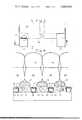
- FIG. 1is an elevation from one side of one section of a bed in accordance with the invention
- FIG. 2is a section taken along line AA in FIG. 1;
- FIG. 3is an elevation from one side of a modified bed section in accordance with the invention.
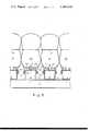
- FIG. 4is a section taken along the line BB in FIG. 3, and,
- FIG. 5is a section similar to FIG. 4 of an alternative embodiment of the invention.
- the Figuresshow a section of a bed including a base portion 1 and inflatable cells 2 (of which only the lower portions are shown) forming a mattress section.
- a number of bed sectionse.g. 3 or 4 are coupled together with articulated connections to form a complete bed as described in our copending British Patent application no. 11942/73 or in the Lancet Oct. 23rd, 1971 pages 885 to 888.
- the base portioncomprises a pair of tubular frame members 3 which form both the frame of the bed and also serve as the supply and exhaust conduits for the air for the inflatable cells.
- a series of cross members or bars 4(one for each cell) which are constructed from wood, steel or other substantially rigid material and which are bolted to the frame members 3 by bolts 5 or loosely located by locating ears on the frame member 3.
- Pairs of blocks 6, of substantially rigid materialare mounted opposite each other on each side of the bed and at spaced intervals along its length. Holes 7 and 8 respectively are formed in each block 6 and are aligned with corresponding holes 9 and 10 in the bar 4 and in the upper wall of tubular members 3. These holes provide for supply of air at low pressure e.g. up to about 5-15 inches water gauge, to the cells and removal of air therefrom. The air may be heated.
- Cross member 4is formed with slots 11 and 12 on each side of blocks 6 and these slots extend across the width of the bed section. Slots 11 and 12 communicate with tubular cavities 13 and 14 formed partly by a hollowed out portion of the bar 4 and partly by a plate 15.
- An inflatable cell 2(which is approximately sausage shaped) extends across the width of the bed section and is in contact at its ends with blocks 6. Each cell 2 is anchored to the bed section 1 by an anchoring arrangement including a pair of ropes l6 and 17 which are received respectively in tubular cavities 13 and 14. Attached to ropes l6 and 17 is a web of material 18 which is in the form of a loop, the ends of the web being connected to the ropes 16 and 17 while the middle portion is attached to or forms the base of cell 2. Each inflatable cell 2 is formed with holes 19 and 20 which are aligned with holes 7 and 8 in the blocks 6.
- Excess materialis provided in the base portion of the inflatable cell 2 in the regions of the holes 19 and 20 so that on inflation of the cell, pressure of air in the cell presses the base of the cell, in the vicinity of holes 19 and 20, firmly into contact with the blocks 6 and thereby forms an air tight seal.
- Individual cellscan be removed from the bed section by slightly deflating the appropriate cell and drawing the cell outwardly i.e., from the plane of the paper in FIG. 2.
- downwardly extending web portions 21 and 22are provided which may be secured by Velcro or similar quick release system to a part of the bed section 1, e.g. to the frame members 3.
- the spaces between blocks 6are filled with a rubber or plastic foam material 23.
- a membrane similar to membrane 24 in FIGS. 4 and 5divides each cell longitudinally and is attached by any suitable means to the cell walls.
- the membraneis aper tured to allow air to circulate through the entire interior of the cells.
- the dimensions of the membraneare chosen so that undue lateral force is not exerted by the cells on neighbouring cells.
- a blanking platemay be slidably mounted on the top surface of each block 6 so that it can be moved from an inoperative position to an operative position where it blanks off the inlet hole 8 and depressurises its associated cell without interfering with the air supply to the remaining cells in the section.
- Web portions 21 and 22are freed from their fastenings and the selected cell can then be drawn out. Replacement of a cell is achieved by the reverse of these operations.
- the frame of the bed sectionis formed from a pair of longitudinally extending tubular frame members 33 upon which are mounted a plurality of cross members 34 which are spaced apart lengthwise of the bed section. Interposed between each pair of adjacent cross members is tubular secondary member 35 having closed ends and a blocked off central portion to prevent air flowing therethrough. Secondary members 35 are clamped at each end to tubular members 33 so that holes in members 33 align with corresponding holes in members 35 in an air-tight manner by means of a seal 41. Air is supplied to each cell 36 from its associated member 35 via a nipple 37 screwed into member 35.
- Each cell 36is formed with a hole into which nipple 37 is received and the material surrounding the hole is reinforced with a rubber annulus 38. Sealing of the cells onto the member 35 is achieved by the pressure of air in the cells. Rimilar provision is made at the other end of the cell for lfow of air from the cell.
- Each cell 36is anchored to the member 35 by webs 39 and 40 extending lengthwise of the cell which are secured to each other by press studs, Velcro or similar material.
- the tops of the cross members 34are padded with plastics or rubber foamed strips 42.
- Membras 24are not necessarily parallel to the top surface of the bed section.
- the membranesmay divide the interior of each cell into a number of honeycomb compartments or may induce the air to flow in a tortuous path through the cell. Air in the cell may be induced in this way to flow generally parallel to the upper surfaces of the cell and this may facilitate control of the temperature of the user of the bed or, by provision ofporous cell fabric, extraction of water vapour or other gases released by wounds or injuries.
- each tublar member 35includes a layer on its top surface of 1 inch thick sponge rubber 50.
- the air cells 36each include two apertures, one adjacent each end with rigid nozzles 51, the rigid nozzles 51 including a collar 52 around their inner end for easy attachment of the nozzles 51 to the air cells.
- the air inlet and/or outlet in the member 35is provided by an aperture 53 through the sponge rubber layer 50 and through the top surface 54 of the tubular member 35.
- the diameter of the aperture through the sponge rubber, layer 50is narrower than the outer .diameter of the nozzleSl so that an air seal is provided.
- a loose layer of material around the nozzle 51 in each air celland betwen the webs 39 and 40 which under the influence of the air pressure within the air cell will provide a seal around each aperture.
- the members 35support the air cells and each member 35 provides a pivot about which the associated air cells may to a limited extent rotate as the patient moves on the bed or if the bed is provided in sections which hinge relative to one another.
- FIG. 5there is provided along each side of the member 35 further bars 55, 56 which are clamped to the side faces of the member 35 by clamping means which are releasable from each end of the member 35.
- the webs 39, 40are wrapped around the bars 55, 56 and anchored thereto by frictional clamping between the bars 55,56 and the side surfaces of the member 35.
- a support appliancewhich comprises a. a plurality of elongated tubular members;
- a support appliance as claimed in claim Ifurther comprising a rigid nozzle member in tight sealing engagement with each of said inlet and outlet apertures.
- a support appliancewhich comprises a. a plurality of elongated tubular members;
- a plurality of elongated inflatable cellseach arranged parallel to one of said tubular members and including a pair of spaced parallel web members attached generally along the length of the exterior of the air cell, said web members extending along opposite sides of the respective tubular member;
- a support appliance as claimed in claim 3 wherein said means for mounting each said cellcomprises means for anchoring said web portions to the opposite sides of each of said elongated tubular members such that the elongated portion of said cell between said web portions and adjacent the surface of said tubular member is maintained relatively slack whereby the air pressure within each air cell presses said slack portion against the surface of said tubular member to provide a seal about said inlet and outlet apertures between the surface of the tubular member and said cell.
- a support appliance as claimed in claim 3wherein said mounting means comprises fixed members spaced on said opposite sides of said tubular members forming narrow elongated slots between said fixed members and said opposite sides of said tubular members, a hem along the free end of each of said web portions and rigid elongated means having a width greater than said slot mounted in each hem whereby each said web member is anchored in one of said slots, movement through said slot being prevented by said rigid elongated means in said hem.
- a support appliance as claimed in claim 3 wherein said mounting meanscomprises a plurality of rigid elongated members mounted adjacent said opposite sides of each of said tubular members, each said web member passing around one of said rigid elongated members to secure said web member between one of said bars and the respective side of a tubular member.
- a support appliancewhich comprises a. a base having a firm surface thereon,
- air inlet and outlet meansextending between said air cell and said base, said air inlet and outlet means comprising holes in said firm surface of said base-aligned with holes in the wall of said cell,
- a support appliancewhich comprises a. a plurality of elongated tubular members
- a support appliance in the form of a bedwhich comprises a. a pair of elongated hollow frame members extending the length of the bed along opposite sides thereof;
- a support appliancewhich comprises a. a plurality of elongated tubular members;
- said plurality of cellsbeing arranged in a plurality of groups, all the cells in one group being adapted to be maintained at one air pressure while the pressure of the remaining groups are independently controllable;
Landscapes
- Invalid Beds And Related Equipment (AREA)
- Mattresses And Other Support Structures For Chairs And Beds (AREA)
Abstract
Description
Claims (10)
Applications Claiming Priority (1)
| Application Number | Priority Date | Filing Date | Title |
|---|---|---|---|
| GB3419772AGB1442994A (en) | 1972-07-21 | 1972-07-21 | Support appliances such as beds |
Publications (1)
| Publication Number | Publication Date |
|---|---|
| US3909858Atrue US3909858A (en) | 1975-10-07 |
Family
ID=10362596
Family Applications (1)
| Application Number | Title | Priority Date | Filing Date |
|---|---|---|---|
| US381646AExpired - LifetimeUS3909858A (en) | 1972-07-21 | 1973-07-23 | Support appliances |
Country Status (2)
| Country | Link |
|---|---|
| US (1) | US3909858A (en) |
| GB (1) | GB1442994A (en) |
Cited By (50)
| Publication number | Priority date | Publication date | Assignee | Title |
|---|---|---|---|---|
| US4488322A (en)* | 1980-02-26 | 1984-12-18 | Hunt William V | Mattress and bed construction |
| EP0182051A1 (en)* | 1984-10-11 | 1986-05-28 | Hans Guldager | Cellular element |
| EP0183012A1 (en)* | 1984-11-27 | 1986-06-04 | Hans Guldager | Cellular element |
| US4638519A (en)* | 1985-04-04 | 1987-01-27 | Air Plus, Inc. | Fluidized hospital bed |
| US4745647A (en)* | 1985-12-30 | 1988-05-24 | Ssi Medical Services, Inc. | Patient support structure |
| US4750224A (en)* | 1986-01-23 | 1988-06-14 | Jochen Simon | Flexible support |
| US4768249A (en)* | 1985-12-30 | 1988-09-06 | Ssi Medical Services, Inc. | Patient support structure |
| US4797962A (en)* | 1986-11-05 | 1989-01-17 | Air Plus, Inc. | Closed loop feedback air supply for air support beds |
| WO1989008439A1 (en)* | 1988-03-14 | 1989-09-21 | Huntleigh Technology Plc | Alternating pressure pad |
| EP0318563A4 (en)* | 1987-06-01 | 1990-02-22 | Kinetic Concepts Inc | AIR BAG FOR THE VIBRATION OF A BED WITH LITTLE AIR LOSS. |
| US4949413A (en)* | 1985-12-30 | 1990-08-21 | Ssi Medical Services, Inc. | Low air loss bed |
| US4953247A (en)* | 1988-05-09 | 1990-09-04 | Hasty Charles E | Air-operated body support device |
| US4962552A (en)* | 1988-05-09 | 1990-10-16 | Hasty Charles E | Air-operated body support device |
| GB2233552A (en)* | 1988-03-14 | 1991-01-16 | Huntleigh Technology Plc | Alternating pressure pad |
| US4989280A (en)* | 1990-02-06 | 1991-02-05 | Bair Richard M | Automatically actuated invalid bed toilet system |
| US5005240A (en)* | 1987-11-20 | 1991-04-09 | Kinetics Concepts, Inc. | Patient support apparatus |
| US5051673A (en)* | 1985-12-30 | 1991-09-24 | Goodwin Vernon L | Patient support structure |
| US5062171A (en)* | 1986-09-09 | 1991-11-05 | Kinetic Concepts, Inc. | Patient support air bags and related system with connectors for detachable mounting of the bags |
| US5065466A (en)* | 1989-03-09 | 1991-11-19 | Ssi Medical Services, Inc. | Quick disconnect coupling for a low air loss patient support |
| US5090077A (en)* | 1991-01-07 | 1992-02-25 | Health Products, Inc. | Cellular patient support for therapeutic air beds |
| US5109560A (en)* | 1991-09-18 | 1992-05-05 | Keisei Medical Industrial Co., Ltd. | Ventilated air mattress with alternately inflatable air cells having communicating upper and lower air chambers |
| WO1992007541A1 (en)* | 1990-11-06 | 1992-05-14 | Bio Clinic Corporation | Fluid filled flotation mattress |
| US5117518A (en)* | 1988-03-14 | 1992-06-02 | Huntleigh Technology, Plc | Pressure controller |
| US5152021A (en)* | 1984-12-17 | 1992-10-06 | Kinetic Concepts, Inc. | Low air loss bag for patient support system |
| US5189742A (en)* | 1992-03-09 | 1993-03-02 | Canon Kabushiki Kaisha | Pressure controlled inflatable pad apparatus |
| US5216768A (en)* | 1988-11-17 | 1993-06-08 | Oliver H. Bodine, Jr. | Bed system |
| US5249318A (en)* | 1988-05-24 | 1993-10-05 | Loadsman Gerald H | Air support cushion |
| EP0566507A1 (en)* | 1992-04-15 | 1993-10-20 | Louis Beaud | Inflatable elements for anti-bed-sore mattresses |
| US5272778A (en)* | 1989-01-25 | 1993-12-28 | The Mediscus Group Inc. | Valve useful in low air loss beds |
| US5373595A (en)* | 1993-03-12 | 1994-12-20 | Irvin Industries Canada Ltd. | Air support device |
| US5560057A (en)* | 1994-07-01 | 1996-10-01 | Madsen; Roger T. | Turning air mattress |
| US5603133A (en)* | 1986-09-09 | 1997-02-18 | Kinetic Concepts, Inc. | Apparatus for alternating pressure of a low air loss patient support system |
| US5606754A (en)* | 1989-03-09 | 1997-03-04 | Ssi Medical Services, Inc. | Vibratory patient support system |
| US5802640A (en)* | 1992-04-03 | 1998-09-08 | Hill-Rom, Inc. | Patient care system |
| US5802645A (en)* | 1984-12-17 | 1998-09-08 | Kinetic Concepts, Inc. | Low air loss bag for patient support |
| US5970550A (en)* | 1996-04-29 | 1999-10-26 | Gazes; Jimmy | Multiple compartment inflatable mattress |
| US5983429A (en)* | 1994-02-15 | 1999-11-16 | Stacy; Richard B. | Method and apparatus for supporting and for supplying therapy to a patient |
| EP0981984A3 (en)* | 1998-08-28 | 2001-03-07 | Happy AG | A mattress for furniture for lying on |
| US6282735B1 (en)* | 1999-08-23 | 2001-09-04 | Hill-Rom Services, Inc. | Hydrotherapy bed |
| US6739009B2 (en)* | 2000-05-26 | 2004-05-25 | Del Drago Marcantonio | Supporting device, notably mattress, mattress support or for a seat |
| US6775859B1 (en) | 2003-03-27 | 2004-08-17 | Seroosh Gorginians | Dual flush toilet |
| US20050275402A1 (en)* | 2004-06-03 | 2005-12-15 | Swen Campagna | Method and control device for operating a magnetic resonance tomography apparatus to select appropriate local coils |
| EP1565132A4 (en)* | 2002-11-08 | 2006-07-19 | Kci Licensing Inc | Patient cooling system |
| US20070073369A1 (en)* | 1998-11-06 | 2007-03-29 | Kci Licensing, Inc. | Patient cooling enclosure |
| US20070250141A1 (en)* | 2002-11-08 | 2007-10-25 | Heaton Keith P | Patient cooling system |
| US7507249B2 (en) | 2002-11-08 | 2009-03-24 | Kci Licensing, Inc. | Patient cooling system |
| US8429774B2 (en) | 2009-08-31 | 2013-04-30 | Hill-Rom Industries Sa | Lateral tilt device |
| US9308393B1 (en) | 2015-01-15 | 2016-04-12 | Dri-Em, Inc. | Bed drying device, UV lights for bedsores |
| US9849052B2 (en)* | 2011-08-16 | 2017-12-26 | Invacare Uk Operations Limited | Pressure relieving mattress |
| US12042453B2 (en) | 2019-02-26 | 2024-07-23 | Hill-Rom Services, Inc. | Patient positioning apparatus and mattress |
Families Citing this family (4)
| Publication number | Priority date | Publication date | Assignee | Title |
|---|---|---|---|---|
| GB8517495D0 (en)* | 1985-07-10 | 1985-08-14 | Mediscus Prod Ltd | Transit mattress |
| US5586348A (en)* | 1987-06-24 | 1996-12-24 | Ahlstrom Consumer Products Ltd. | Air mattress and method for adjusting it |
| US5621934A (en)* | 1988-06-22 | 1997-04-22 | A. Ahlstrom Corporation | Mattress |
| GB9421912D0 (en)* | 1994-11-01 | 1994-12-21 | Karomed Ltd | Inflatable mattress |
Citations (6)
| Publication number | Priority date | Publication date | Assignee | Title |
|---|---|---|---|---|
| US277979A (en)* | 1882-12-12 | 1883-05-22 | evans | |
| US558605A (en)* | 1896-04-21 | John gimbel | ||
| US945234A (en)* | 1908-12-12 | 1910-01-04 | Hinsdale Pneumatic Cushion And Mattress Company | Pneumatic mattress. |
| US1038351A (en)* | 1912-06-28 | 1912-09-10 | William J Graham | Waterproof bag. |
| US3303518A (en)* | 1962-03-05 | 1967-02-14 | Ingram George | Inflatable mattresses, pillows and cushions |
| US3399407A (en)* | 1966-05-03 | 1968-09-03 | Thomas O. Olsen | Cushion for decelerating falling bodies |
- 1972
- 1972-07-21GBGB3419772Apatent/GB1442994A/ennot_activeExpired
- 1973
- 1973-07-23USUS381646Apatent/US3909858A/ennot_activeExpired - Lifetime
Patent Citations (6)
| Publication number | Priority date | Publication date | Assignee | Title |
|---|---|---|---|---|
| US558605A (en)* | 1896-04-21 | John gimbel | ||
| US277979A (en)* | 1882-12-12 | 1883-05-22 | evans | |
| US945234A (en)* | 1908-12-12 | 1910-01-04 | Hinsdale Pneumatic Cushion And Mattress Company | Pneumatic mattress. |
| US1038351A (en)* | 1912-06-28 | 1912-09-10 | William J Graham | Waterproof bag. |
| US3303518A (en)* | 1962-03-05 | 1967-02-14 | Ingram George | Inflatable mattresses, pillows and cushions |
| US3399407A (en)* | 1966-05-03 | 1968-09-03 | Thomas O. Olsen | Cushion for decelerating falling bodies |
Cited By (73)
| Publication number | Priority date | Publication date | Assignee | Title |
|---|---|---|---|---|
| US4525885A (en)* | 1980-02-26 | 1985-07-02 | Mediscus Products Limited | Support appliance for mounting on a standard hospital bed |
| US4488322A (en)* | 1980-02-26 | 1984-12-18 | Hunt William V | Mattress and bed construction |
| US4651369A (en)* | 1984-10-11 | 1987-03-24 | Hans Guldager | Cellular element |
| EP0182051A1 (en)* | 1984-10-11 | 1986-05-28 | Hans Guldager | Cellular element |
| EP0183012A1 (en)* | 1984-11-27 | 1986-06-04 | Hans Guldager | Cellular element |
| US4646373A (en)* | 1984-11-27 | 1987-03-03 | Hans Guldager | Cellular element |
| US5802645A (en)* | 1984-12-17 | 1998-09-08 | Kinetic Concepts, Inc. | Low air loss bag for patient support |
| US5152021A (en)* | 1984-12-17 | 1992-10-06 | Kinetic Concepts, Inc. | Low air loss bag for patient support system |
| US4638519A (en)* | 1985-04-04 | 1987-01-27 | Air Plus, Inc. | Fluidized hospital bed |
| US6282737B1 (en) | 1985-10-04 | 2001-09-04 | John H. Vrzalik | Apparatus for alternating pressure of a low air loss patient support |
| US4745647A (en)* | 1985-12-30 | 1988-05-24 | Ssi Medical Services, Inc. | Patient support structure |
| US5051673A (en)* | 1985-12-30 | 1991-09-24 | Goodwin Vernon L | Patient support structure |
| US4768249A (en)* | 1985-12-30 | 1988-09-06 | Ssi Medical Services, Inc. | Patient support structure |
| US4949413A (en)* | 1985-12-30 | 1990-08-21 | Ssi Medical Services, Inc. | Low air loss bed |
| US4750224A (en)* | 1986-01-23 | 1988-06-14 | Jochen Simon | Flexible support |
| US5603133A (en)* | 1986-09-09 | 1997-02-18 | Kinetic Concepts, Inc. | Apparatus for alternating pressure of a low air loss patient support system |
| US5062171A (en)* | 1986-09-09 | 1991-11-05 | Kinetic Concepts, Inc. | Patient support air bags and related system with connectors for detachable mounting of the bags |
| EP0261830A3 (en)* | 1986-09-26 | 1989-06-28 | Ssi Medical Services, Inc. | Improved patient support structure |
| US4797962A (en)* | 1986-11-05 | 1989-01-17 | Air Plus, Inc. | Closed loop feedback air supply for air support beds |
| EP0318563A4 (en)* | 1987-06-01 | 1990-02-22 | Kinetic Concepts Inc | AIR BAG FOR THE VIBRATION OF A BED WITH LITTLE AIR LOSS. |
| US5005240A (en)* | 1987-11-20 | 1991-04-09 | Kinetics Concepts, Inc. | Patient support apparatus |
| US5117518A (en)* | 1988-03-14 | 1992-06-02 | Huntleigh Technology, Plc | Pressure controller |
| US5109561A (en)* | 1988-03-14 | 1992-05-05 | Huntleigh Technology, Plc | Alternating pressure pad |
| GB2233552A (en)* | 1988-03-14 | 1991-01-16 | Huntleigh Technology Plc | Alternating pressure pad |
| GB2241164B (en)* | 1988-03-14 | 1991-11-27 | Huntleigh Technology Plc | Alternating pressure pad |
| GB2233552B (en)* | 1988-03-14 | 1991-11-27 | Huntleigh Technology Plc | Alternating pressure pad |
| WO1989008439A1 (en)* | 1988-03-14 | 1989-09-21 | Huntleigh Technology Plc | Alternating pressure pad |
| GB2241164A (en)* | 1988-03-14 | 1991-08-28 | Huntleigh Technology Plc | Alternating pressure pad |
| US6941598B2 (en) | 1988-03-23 | 2005-09-13 | Hill-Rom Services, Inc. | Patient care system |
| US6668408B2 (en) | 1988-03-23 | 2003-12-30 | Hill-Rom Services, Inc. | Patient care system |
| US4962552A (en)* | 1988-05-09 | 1990-10-16 | Hasty Charles E | Air-operated body support device |
| US4953247A (en)* | 1988-05-09 | 1990-09-04 | Hasty Charles E | Air-operated body support device |
| US5249318A (en)* | 1988-05-24 | 1993-10-05 | Loadsman Gerald H | Air support cushion |
| US5216768A (en)* | 1988-11-17 | 1993-06-08 | Oliver H. Bodine, Jr. | Bed system |
| US5272778A (en)* | 1989-01-25 | 1993-12-28 | The Mediscus Group Inc. | Valve useful in low air loss beds |
| US6820640B2 (en) | 1989-03-09 | 2004-11-23 | Hill-Rom Services, Inc. | Vibratory patient support system |
| US5606754A (en)* | 1989-03-09 | 1997-03-04 | Ssi Medical Services, Inc. | Vibratory patient support system |
| US6098222A (en)* | 1989-03-09 | 2000-08-08 | Hill-Rom Company, Inc. | Vibratory patient support system |
| US6415814B1 (en) | 1989-03-09 | 2002-07-09 | Hill-Rom Services, Inc. | Vibratory patient support system |
| US5065466A (en)* | 1989-03-09 | 1991-11-19 | Ssi Medical Services, Inc. | Quick disconnect coupling for a low air loss patient support |
| US4989280A (en)* | 1990-02-06 | 1991-02-05 | Bair Richard M | Automatically actuated invalid bed toilet system |
| US5235713A (en)* | 1990-11-06 | 1993-08-17 | Bio Clinic Corporation | Fluid filled flotation mattress |
| WO1992007541A1 (en)* | 1990-11-06 | 1992-05-14 | Bio Clinic Corporation | Fluid filled flotation mattress |
| US5090077A (en)* | 1991-01-07 | 1992-02-25 | Health Products, Inc. | Cellular patient support for therapeutic air beds |
| US5109560A (en)* | 1991-09-18 | 1992-05-05 | Keisei Medical Industrial Co., Ltd. | Ventilated air mattress with alternately inflatable air cells having communicating upper and lower air chambers |
| US5189742A (en)* | 1992-03-09 | 1993-03-02 | Canon Kabushiki Kaisha | Pressure controlled inflatable pad apparatus |
| US5802640A (en)* | 1992-04-03 | 1998-09-08 | Hill-Rom, Inc. | Patient care system |
| EP0566507A1 (en)* | 1992-04-15 | 1993-10-20 | Louis Beaud | Inflatable elements for anti-bed-sore mattresses |
| FR2690074A1 (en)* | 1992-04-15 | 1993-10-22 | Beaud Louis | Inflatable elements for anti-decubitus mattresses. |
| US5373595A (en)* | 1993-03-12 | 1994-12-20 | Irvin Industries Canada Ltd. | Air support device |
| US5983429A (en)* | 1994-02-15 | 1999-11-16 | Stacy; Richard B. | Method and apparatus for supporting and for supplying therapy to a patient |
| US5560057A (en)* | 1994-07-01 | 1996-10-01 | Madsen; Roger T. | Turning air mattress |
| US5970550A (en)* | 1996-04-29 | 1999-10-26 | Gazes; Jimmy | Multiple compartment inflatable mattress |
| EP0981984A3 (en)* | 1998-08-28 | 2001-03-07 | Happy AG | A mattress for furniture for lying on |
| US7555792B2 (en) | 1998-11-06 | 2009-07-07 | Kci Licensing, Inc. | Patient cooling enclosure |
| US7818835B2 (en) | 1998-11-06 | 2010-10-26 | Kci Licensing, Inc. | Patient cooling enclosure |
| US20090216304A1 (en)* | 1998-11-06 | 2009-08-27 | Kci Licensing, Inc. | Patient Cooling Enclosure |
| US20070073369A1 (en)* | 1998-11-06 | 2007-03-29 | Kci Licensing, Inc. | Patient cooling enclosure |
| US6282735B1 (en)* | 1999-08-23 | 2001-09-04 | Hill-Rom Services, Inc. | Hydrotherapy bed |
| US6739009B2 (en)* | 2000-05-26 | 2004-05-25 | Del Drago Marcantonio | Supporting device, notably mattress, mattress support or for a seat |
| US8021407B2 (en) | 2002-11-08 | 2011-09-20 | Kci Licensing, Inc. | Patient cooling system |
| EP1864633A3 (en)* | 2002-11-08 | 2008-05-21 | KCI Licensing, Inc. | Patent cooling system |
| US7507249B2 (en) | 2002-11-08 | 2009-03-24 | Kci Licensing, Inc. | Patient cooling system |
| US20070250141A1 (en)* | 2002-11-08 | 2007-10-25 | Heaton Keith P | Patient cooling system |
| EP1565132A4 (en)* | 2002-11-08 | 2006-07-19 | Kci Licensing Inc | Patient cooling system |
| CN1720011B (en)* | 2002-11-08 | 2012-05-30 | Kci许可有限公司 | Patient cooling system |
| US6775859B1 (en) | 2003-03-27 | 2004-08-17 | Seroosh Gorginians | Dual flush toilet |
| US20050275402A1 (en)* | 2004-06-03 | 2005-12-15 | Swen Campagna | Method and control device for operating a magnetic resonance tomography apparatus to select appropriate local coils |
| US8429774B2 (en) | 2009-08-31 | 2013-04-30 | Hill-Rom Industries Sa | Lateral tilt device |
| US8601622B1 (en) | 2009-08-31 | 2013-12-10 | Hill-Rom Industries S.A. | Patient support apparatus including a lateral tilt device |
| US9849052B2 (en)* | 2011-08-16 | 2017-12-26 | Invacare Uk Operations Limited | Pressure relieving mattress |
| US9308393B1 (en) | 2015-01-15 | 2016-04-12 | Dri-Em, Inc. | Bed drying device, UV lights for bedsores |
| US12042453B2 (en) | 2019-02-26 | 2024-07-23 | Hill-Rom Services, Inc. | Patient positioning apparatus and mattress |
Also Published As
| Publication number | Publication date |
|---|---|
| GB1442994A (en) | 1976-07-21 |
Similar Documents
| Publication | Publication Date | Title |
|---|---|---|
| US3909858A (en) | Support appliances | |
| US3822425A (en) | Inflatable support appliance | |
| US6079070A (en) | Disposable inflatable inclinable cushion | |
| US4139920A (en) | Polymorphic support systems | |
| US2684672A (en) | Body support device | |
| US5304271A (en) | Method of making a fluid cushion | |
| US3674019A (en) | Dual layer cellular inflatable pad | |
| US3653083A (en) | Bed pad | |
| US6209159B1 (en) | Pressure reducing cushion with selective pressure point relief | |
| US3428974A (en) | Compartmented air mattress | |
| US4777679A (en) | Inflatable cushion with central opening | |
| EP0224558A4 (en) | Hemorrhoid seat cushion. | |
| JPH02504231A (en) | alternating pressure pad | |
| EP0878150A2 (en) | Inflatable support | |
| US3984886A (en) | Fluid-filled cushioning assemblies | |
| US5586348A (en) | Air mattress and method for adjusting it | |
| GB2362567A (en) | A modular inflatable cushion | |
| US20080047071A1 (en) | Tension free wheelchair seat cover and cushion therewith | |
| US5027454A (en) | Combined bed structure | |
| US2345421A (en) | Pneumatic mattress | |
| US20050060809A1 (en) | Methods and devices for reducing stress concentration when supporting a body | |
| GB1576641A (en) | Pressure point pads | |
| JP3706388B2 (en) | Banded cell type cushion | |
| US1777477A (en) | Pneumatic cushion, mattress, and the like | |
| GB2108837A (en) | Air flotation mattress |
Legal Events
| Date | Code | Title | Description |
|---|---|---|---|
| AS | Assignment | Owner name:MEDISCUS PRODUCTS LIMITED, WESTMINSTER ROAD, WAREH Free format text:ASSIGNMENT OF ASSIGNORS INTEREST.;ASSIGNOR:WATKINS & WATSON LIMITED;REEL/FRAME:004263/0466 Effective date:19840327 Owner name:MEDISCUS PRODUCTS LIMITED,VIRGIN ISLANDS, BRITISH Free format text:ASSIGNMENT OF ASSIGNORS INTEREST;ASSIGNOR:WATKINS & WATSON LIMITED;REEL/FRAME:004263/0466 Effective date:19840327 | |
| AS | Assignment | Owner name:MEDISCUS PRODUCTS INC., 13135 CHAMPIONS DRIVE SUI Free format text:ASSIGNMENT OF ASSIGNORS INTEREST.;ASSIGNOR:MEDISCUS PRODUCT LIMITED A BRITISH COMPANY;REEL/FRAME:004433/0171 Effective date:19850607 | |
| AS | Assignment | Owner name:SSI MEDICAL SERVICES, INC., SOUTH CAROLINA Free format text:ASSIGNMENT OF ASSIGNORS INTEREST;ASSIGNOR:MEDISCUS PRODUCTS, INC.;REEL/FRAME:012506/0655 Effective date:20011128 |