US3902495A - Flow control system - Google Patents
Flow control systemDownload PDFInfo
- Publication number
- US3902495A US3902495AUS437165AUS43716574AUS3902495AUS 3902495 AUS3902495 AUS 3902495AUS 437165 AUS437165 AUS 437165AUS 43716574 AUS43716574 AUS 43716574AUS 3902495 AUS3902495 AUS 3902495A
- Authority
- US
- United States
- Prior art keywords
- fluid
- chamber
- pressure
- flow
- per
- Prior art date
- Legal status (The legal status is an assumption and is not a legal conclusion. Google has not performed a legal analysis and makes no representation as to the accuracy of the status listed.)
- Expired - Lifetime
Links
- 239000012530fluidSubstances0.000claimsabstractdescription176
- 210000002159anterior chamberAnatomy0.000claimsabstractdescription43
- 230000002262irrigationEffects0.000claimsabstractdescription27
- 238000003973irrigationMethods0.000claimsabstractdescription27
- 238000004891communicationMethods0.000claimsabstractdescription16
- 238000000034methodMethods0.000claimsdescription14
- 230000004044responseEffects0.000claimsdescription10
- 238000005086pumpingMethods0.000claimsdescription8
- 208000002177CataractDiseases0.000abstractdescription16
- 238000003780insertionMethods0.000abstractdescription4
- 230000037431insertionEffects0.000abstractdescription4
- 238000004945emulsificationMethods0.000abstractdescription2
- 239000000463materialSubstances0.000description7
- 210000001519tissueAnatomy0.000description5
- 210000003128headAnatomy0.000description4
- 239000002245particleSubstances0.000description4
- 230000001276controlling effectEffects0.000description3
- 239000002775capsuleSubstances0.000description2
- 238000010586diagramMethods0.000description2
- 238000006073displacement reactionMethods0.000description2
- 230000005484gravityEffects0.000description2
- 230000006872improvementEffects0.000description2
- 230000004048modificationEffects0.000description2
- 238000012986modificationMethods0.000description2
- 230000002572peristaltic effectEffects0.000description2
- 210000004872soft tissueAnatomy0.000description2
- 230000001052transient effectEffects0.000description2
- 241001538365Accipiter nisusSpecies0.000description1
- 230000009471actionEffects0.000description1
- 230000000903blocking effectEffects0.000description1
- 239000003990capacitorSubstances0.000description1
- 230000008859changeEffects0.000description1
- 210000004087corneaAnatomy0.000description1
- 230000006837decompressionEffects0.000description1
- 210000003038endotheliumAnatomy0.000description1
- 238000013467fragmentationMethods0.000description1
- 238000006062fragmentation reactionMethods0.000description1
- 230000000266injurious effectEffects0.000description1
- QSHDDOUJBYECFT-UHFFFAOYSA-NmercuryChemical compound[Hg]QSHDDOUJBYECFT-UHFFFAOYSA-N0.000description1
- 229910052753mercuryInorganic materials0.000description1
- 238000012544monitoring processMethods0.000description1
- 230000001105regulatory effectEffects0.000description1
- 230000035939shockEffects0.000description1
- 239000007787solidSubstances0.000description1
- 238000001356surgical procedureMethods0.000description1
- 239000000725suspensionSubstances0.000description1
Images
Classifications
- A—HUMAN NECESSITIES
- A61—MEDICAL OR VETERINARY SCIENCE; HYGIENE
- A61M—DEVICES FOR INTRODUCING MEDIA INTO, OR ONTO, THE BODY; DEVICES FOR TRANSDUCING BODY MEDIA OR FOR TAKING MEDIA FROM THE BODY; DEVICES FOR PRODUCING OR ENDING SLEEP OR STUPOR
- A61M3/00—Medical syringes, e.g. enemata; Irrigators
- A61M3/02—Enemata; Irrigators
- A61M3/0233—Enemata; Irrigators characterised by liquid supply means, e.g. from pressurised reservoirs
- A61M3/0241—Enemata; Irrigators characterised by liquid supply means, e.g. from pressurised reservoirs the liquid being supplied by gravity
- A—HUMAN NECESSITIES
- A61—MEDICAL OR VETERINARY SCIENCE; HYGIENE
- A61M—DEVICES FOR INTRODUCING MEDIA INTO, OR ONTO, THE BODY; DEVICES FOR TRANSDUCING BODY MEDIA OR FOR TAKING MEDIA FROM THE BODY; DEVICES FOR PRODUCING OR ENDING SLEEP OR STUPOR
- A61M1/00—Suction or pumping devices for medical purposes; Devices for carrying-off, for treatment of, or for carrying-over, body-liquids; Drainage systems
- A61M1/71—Suction drainage systems
- A61M1/74—Suction control
- A61M1/742—Suction control by changing the size of a vent
- A—HUMAN NECESSITIES
- A61—MEDICAL OR VETERINARY SCIENCE; HYGIENE
- A61M—DEVICES FOR INTRODUCING MEDIA INTO, OR ONTO, THE BODY; DEVICES FOR TRANSDUCING BODY MEDIA OR FOR TAKING MEDIA FROM THE BODY; DEVICES FOR PRODUCING OR ENDING SLEEP OR STUPOR
- A61M1/00—Suction or pumping devices for medical purposes; Devices for carrying-off, for treatment of, or for carrying-over, body-liquids; Drainage systems
- A61M1/71—Suction drainage systems
- A61M1/77—Suction-irrigation systems
- A—HUMAN NECESSITIES
- A61—MEDICAL OR VETERINARY SCIENCE; HYGIENE
- A61M—DEVICES FOR INTRODUCING MEDIA INTO, OR ONTO, THE BODY; DEVICES FOR TRANSDUCING BODY MEDIA OR FOR TAKING MEDIA FROM THE BODY; DEVICES FOR PRODUCING OR ENDING SLEEP OR STUPOR
- A61M3/00—Medical syringes, e.g. enemata; Irrigators
- A61M3/02—Enemata; Irrigators
- A61M3/0204—Physical characteristics of the irrigation fluid, e.g. conductivity or turbidity
- A61M3/0208—Physical characteristics of the irrigation fluid, e.g. conductivity or turbidity before use
- A—HUMAN NECESSITIES
- A61—MEDICAL OR VETERINARY SCIENCE; HYGIENE
- A61M—DEVICES FOR INTRODUCING MEDIA INTO, OR ONTO, THE BODY; DEVICES FOR TRANSDUCING BODY MEDIA OR FOR TAKING MEDIA FROM THE BODY; DEVICES FOR PRODUCING OR ENDING SLEEP OR STUPOR
- A61M3/00—Medical syringes, e.g. enemata; Irrigators
- A61M3/02—Enemata; Irrigators
- A61M3/0204—Physical characteristics of the irrigation fluid, e.g. conductivity or turbidity
- A61M3/0212—Physical characteristics of the irrigation fluid, e.g. conductivity or turbidity after use
- A—HUMAN NECESSITIES
- A61—MEDICAL OR VETERINARY SCIENCE; HYGIENE
- A61M—DEVICES FOR INTRODUCING MEDIA INTO, OR ONTO, THE BODY; DEVICES FOR TRANSDUCING BODY MEDIA OR FOR TAKING MEDIA FROM THE BODY; DEVICES FOR PRODUCING OR ENDING SLEEP OR STUPOR
- A61M3/00—Medical syringes, e.g. enemata; Irrigators
- A61M3/02—Enemata; Irrigators
- A61M3/0204—Physical characteristics of the irrigation fluid, e.g. conductivity or turbidity
- A61M3/0216—Pressure
- A—HUMAN NECESSITIES
- A61—MEDICAL OR VETERINARY SCIENCE; HYGIENE
- A61M—DEVICES FOR INTRODUCING MEDIA INTO, OR ONTO, THE BODY; DEVICES FOR TRANSDUCING BODY MEDIA OR FOR TAKING MEDIA FROM THE BODY; DEVICES FOR PRODUCING OR ENDING SLEEP OR STUPOR
- A61M3/00—Medical syringes, e.g. enemata; Irrigators
- A61M3/02—Enemata; Irrigators
- A61M3/0204—Physical characteristics of the irrigation fluid, e.g. conductivity or turbidity
- A61M3/022—Volume; Flow rate
- A—HUMAN NECESSITIES
- A61—MEDICAL OR VETERINARY SCIENCE; HYGIENE
- A61F—FILTERS IMPLANTABLE INTO BLOOD VESSELS; PROSTHESES; DEVICES PROVIDING PATENCY TO, OR PREVENTING COLLAPSING OF, TUBULAR STRUCTURES OF THE BODY, e.g. STENTS; ORTHOPAEDIC, NURSING OR CONTRACEPTIVE DEVICES; FOMENTATION; TREATMENT OR PROTECTION OF EYES OR EARS; BANDAGES, DRESSINGS OR ABSORBENT PADS; FIRST-AID KITS
- A61F9/00—Methods or devices for treatment of the eyes; Devices for putting in contact-lenses; Devices to correct squinting; Apparatus to guide the blind; Protective devices for the eyes, carried on the body or in the hand
- A—HUMAN NECESSITIES
- A61—MEDICAL OR VETERINARY SCIENCE; HYGIENE
- A61M—DEVICES FOR INTRODUCING MEDIA INTO, OR ONTO, THE BODY; DEVICES FOR TRANSDUCING BODY MEDIA OR FOR TAKING MEDIA FROM THE BODY; DEVICES FOR PRODUCING OR ENDING SLEEP OR STUPOR
- A61M2210/00—Anatomical parts of the body
- A61M2210/06—Head
- A61M2210/0612—Eyes
- A—HUMAN NECESSITIES
- A61—MEDICAL OR VETERINARY SCIENCE; HYGIENE
- A61M—DEVICES FOR INTRODUCING MEDIA INTO, OR ONTO, THE BODY; DEVICES FOR TRANSDUCING BODY MEDIA OR FOR TAKING MEDIA FROM THE BODY; DEVICES FOR PRODUCING OR ENDING SLEEP OR STUPOR
- A61M3/00—Medical syringes, e.g. enemata; Irrigators
- A61M3/02—Enemata; Irrigators
- A61M3/0233—Enemata; Irrigators characterised by liquid supply means, e.g. from pressurised reservoirs
Definitions
- the systemcomprises a handpiece with an (ultrasonically vibrated) hollow tip, the hollow tip being connected to the fluid withdrawal or aspirating portion, while an annular passage around the tip is used to introduce fluid for irrigation purposes.
- the aspirating portioncomprises a withdrawal hose attached to the output manifold of the handpiece in fluid communication with the hollow tip, a constant flow pump attached to the other ehd of the withdrawal hose, and a vacuum relief valve connected to the withdrawal hose intermediate the pump and the handpiece.
- the irrigation portioncomchamber of the eye during removal of a cataract by insertion of the handpiece tip into the eye chamber.
- This applicationrelates to an improvement in the control of fluid flow in a surgical device. More particularly this invention relates to an improvement in the fluid flow systems for a surgical device useful in cataract removal such as that shown by U.S. Pat. No. 3,589,363 issued June 29, 1971 to A. Banko and C. D. Kelman for a Material Removal Apparatus and Method Employing High Frequency Vibrations.
- the aforesaid patentdescribes an instrument for breaking apart and removing unwanted tissue and material especially a cataract located in the anterior chamber of the eye by ultrasonically fragmenting the cataract while simultaneously introducing fluid into the eye chamber, and withdrawing the fluid and fragmented cataract particles.
- the device describedincludes a handpiece having an operative tip vibrating in the ultrasonic range which is also hollow and is in turn surrounded by a tubular sleeve.
- the tip of the handpiece including the surrounding tubular sleeveare inserted into the anterior chamber of the eye.
- Treatment fluidis introduced through the hollow sleeve at a constant low pressure.
- This introduction of fluid which is called irrigationis to provide a replacement for fluid withdrawn or lost from the eye chamber.
- the withdrawl of fluid and suspended material from the anterior chamberis specifically called aspiration and ideally there is no change in fluid content or anterior chamber pressure as a result of irrigation-aspiration. This of course is impossible to achieve since aspiration is intended to remove solids which until broken up sometimes tend to occlude or block the fluid withdrawal openings of the handpiece.
- a handpiece described in the aforesaid U.S. Pat. as well as the instrumentation described in U.S. Pat. No. 3,589,363provides a tool tip insertable in the anterior chamber of the eye with an annular nozzle for supply of fluid for irrigation, a hollow tool tip which is vibrated at about 40,000 cps to provide the energy to break up the cataract and allow fluid withdrawal for aspirating the reduced particles and fluid.
- a handpieceWhen the handpiece is inserted into the eye, it is extremely important to maintain the fluid pressure of the chamber within a certain range and to prevent rapid fluctuations of the pressure and fluid content of the chamber.
- the handpieceis inserted into the chamber through a small incision and the fluid flow adjusted to the desired level principally by the height at which the irrigation fluid source is supported to provide a gravity flow into the eye, and the speed of a constant flow positive displacement pump in the piping from the eye to withdraw the aspirating stream.
- the surgeonthen moves the cataract lens into the anterior chamber, applies the ultrasonic vibration to the tip of the handpiece in contact with the lens and proceeds to break up the lens.
- the opening in the tip through which aspiration proceedsis periodically occluded by lens material.
- fluidis prevented from entering the hollow tip, although the constant flow pump continues to operate.
- the pump operationthus starts drawing a vacuum in the conduit between the handpiece tip and the pump.
- the pressure from the gravity feed of irrigation fluid into the eyeremains constant and increases fluid pressure in the anterior chamber of they eye, expanding it somewhat.
- the high vacuum existing in the aspirating systemtends to quickly withdraw fluid from the anterior chamber. This may rapidly decompress the anterior chamber and draw the enclosing tissues towards the handpiece tip.
- a fluidic flow systemfor use in the irrigation and aspiration of a small elastic pressure responsive chamber.
- the systemcomprises: a fluid source under substantially constant pressure; fluid inflow means connected to the fluid source for limiting flow of the fluid from the source into the chamber thereby providing irrigation fluid at a predetermined limited flow rate and pressure into the chamber; fluid withdrawal means in fluid communication with the chamber for aspirating fluid from the chamber at a rate to eliminate transient pressure shocks to the chamber; a constant flow pump connected to the other end of the fluid withdrawal means, with the pump acting to draw fluid from the chamber through the withdrawal means; and the withdrawal means including a pressure differential relief valve intermediate the chamber and the pump, the relief valve responsively opening at a predetermined pressure differential which in combination with the parameters of the fluid withdrawal means limits the occurrence of pressure transients communicated to the chamber, whereby flow resistivity of the withdrawal means between the chamber and the valve attenuates the pressure changes transmitted to the chamber when the valve opens in response to the predetermined pressure differential between atmosphere and the pressure in
- the relief valveopens to atmosphere in response to a pressure differential of from 10 mm of mercury (Hg) to I mm Hg; the pressure of the fluid source is in the range of from to I00 mm Hg; the flow resistivity of the inflow means is from 0.042 to 18.5 mm Hg per ml per min; the flow resistivity of the fluid withdrawal means is from 0.35 to 21.5 mm Hg per ml per min; and the constant flow volume of the pump is from 5 to 50 ml per min.
- Hgmm of mercury
- I mm Hgthe pressure of the fluid source
- the pressure of the fluid sourceis in the range of from to I00 mm Hg
- the flow resistivity of the inflow meansis from 0.042 to 18.5 mm Hg per ml per min
- the flow resistivity of the fluid withdrawal meansis from 0.35 to 21.5 mm Hg per ml per min
- the constant flow volume of the pumpis from 5 to 50 ml per min.
- the preferred pressure, flow and flow resistivity ranges of the system according to the present inventioncomprise the following: a fluid source exerting a constant pressure of from 30 to 60 mm Hg; the inflow means having a flow resistivity of from 0.5 to 2.5 mm Hg. ml per min between the fluid source at one end and to the operative volume of the anterior chamber of an eye at the other end; the fluid withdrawal means having a flow resistivity of from 1.33 to 3.0 mm Hg. per ml per min.
- the constant volume pumphaving a flow rate of from to ml per min; and the relief valve connected to the flow withdrawal means intermediate the pump and the eye chamber responsively opening the atmosphere at a pressure differential of between about 30 and 50 mm Hg.
- Another object of the present inventionis to provide an effective flow control system for irrigating and aspirating the anterior chamber of the eye.
- Yet another object of the present inventionis to provide a flow control system for effectively limiting the transient pressure and flow changes as felt by the anterior chamber of the eye during irrigation and aspiration thereof.
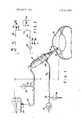
- FIG. 1 of the drawingsis a diagram of the fluidic flow control system of the present invention.
- FIG. 2 of the drawingsis an electrical circuit analog of the flow control system of FIG. 1.
- the apparatusincludes a handpiece having an operative tip vibrating at a frequency in the ultrasonic range (preferably about 40.000 cps) with an amplitude controllable up to several thousandths of an inch.
- the operative tipis itself hollow and is in turn surrounded by a tubular sleeve forming an annular passage.
- the inflow fluid for irrigating the anterior chamber of the eyeis introduced into the chamber through the annular passage and the broken up material. small particles and fluid in the eye, is withdrawn at the same time through the hollow tip to aspirate the chamber.
- FIG. 1 of the drawingswherein a simplified diagram of a handpiece 12 is shown with an operative tip 14 having a hollow withdrawal means 16, and an annular passage 18 surrounding the tip 14 for introducing fluid into an anterior chamber 20 of an eye undergoing cataract surgery.
- a simplified diagram of a handpiece 12is shown with an operative tip 14 having a hollow withdrawal means 16, and an annular passage 18 surrounding the tip 14 for introducing fluid into an anterior chamber 20 of an eye undergoing cataract surgery.
- Irrigation fluidis introduced into the handpiece 12 via an inflow hose 22 which is connected at one end to the handpiece and at the other end to an administration set 23. that is a hose connected to an irrigation fluid supply bottle 24 suspended by an appropriate bracket (not shown) a fixed height I: over the level of the hand piece and eye.
- the fixed height h at which the fluid supply bottle is suspendedacts to apply a fixed fluid pressure to fluid entering the hose 22 from the bottle to the eye.
- the selected heightis such as to apply a pressure of from about l0 mm Hg to about I00 mm Hg to fluid entering the administration set and thereby furnish a fluid source having a constant preselected pressure level in relation to the handpiece.
- the height at which the supply bottle is suspendedis such as to apply a pressure head of from 30 mm Hg to 60 mm Hg. According to the present invention, this is the sole means for supplying the pressure head which forces the flow of fluid from the bottle through the administration set 23, the inflow hose 22 and the annular passage of the handpiece into the anterior chamber of the eye.
- the pressure which is internally applied to the eyeis of prime importance.
- pressure of the anterior chamber of the eyeit is very important that pressure of the anterior chamber of the eye be maintained within a certain range of values to prevent damage thereto.
- a collapse of the anterior chamber due to reduced pressurecould result in either the iris. the endothelium layer of the cornea. or the posterior capsule as well as other soft tissue. coming in contact with the operating tip of the handpiece.
- This problem of maintaining the proper pressureis a particularly difficult and sensitive one in the case of an operative site such as the anterior chamber, which is considerably smaller in volume than the volume of fluid necessary for continuous irrigation and aspirationv
- the anterior chamber of the eyeis. of course, in the same pressure related system as the apparatus of this invention.
- the present inventionprovides an irrigation system which limits the fluid pressure to which the anterior chamber of the eye is subject by limiting the height at which the irrigation fluid supply is maintained in reference to the eye, and by further limiting the flow rate into the eye utilizing specified inflow means having a specified resistivity to flow. as well as relating the irrigation system to the fluid withdrawal or aspiration system. That portion of the fluidic system comprising the fluid withdrawal means, the constant flow pump and the differential pressure relief valve act in combination to limit fluid flow from the eye, and more importantly prevent sudden pressure changes or pressure transients from occuring by increasing the time period over which the pressure changes occur and by limiting the maximum pressure drop to which theeye would be exposed. This is accomplished by controlling the constant flow rate of the pump; by setting a predetermined limit to the pressure differential, the relief valve will open to atmosphere; and by controlling the flow resistivity of the fluid piping as herein described.
- the operative tip 14 of the handpieceis hollow and has an internal fluid withdrawal passage 30 constituting part of the fluid withdrawal system of the present invention utilized in aspirating the operative site of the eye.
- a fluid withdrawal pipe 32is connected to the handpiece at one end and is in fluid communication with the fluid withdrawal passage.
- the other end of the fluid withdrawal pipeis connected to a constant flow pump 34 preferably a constant displacement, variable speed, peristaltic pump.
- the peristaltic featureacts to avoid any contact of the operating parts with the withdrawn fluid suspension.
- a relief valve 36is connected by a T joint 38 to the fluid withdrawal pipe and is set to open to atmosphere should the pressure differential in the fluid withdrawal pipe exceed a predetermined pressure, which pressure may be from 30 mm Hg to 50 mm Hg.
- a pressure differential at which the relief valve opensis a pressure of about 40 mm Hg.
- Constant flow capacity of the pumpis preferably a flow of from about ml per min to ml per minute.
- Flow resistivity of the fluid withdrawal means at these preferred conditionsis from about l.33 mm Hg to about 3.0 mm Hg.
- Flow resistivity in the fluid inflow systemis on the order of from about 0.5 to about 2.5 mm Hg per ml per min.
- FIG. 2 of the drawingshows the electrical analog circuit which led to the fluidic control system of this invention.
- each part of our inventionfunctions in relation to a moderately uncontrollable set of conditions imposed by the needs of the operative site, i.e., anterior chamber of human eye and the size of the operative incision.
- the conditions in the anterior chamber of the eyeare analogized by two electrical elements which are a resistive element 44 to account for flow resistivity through the incision, and a capacitor 45 to correspond to elasticity of the eye chamber, both elements being in parallel and connected to ground at one end and at the other end to the inflow irrigation system and the fluid withdrawal system.
- the fluid inflow systemis analogized by a constant voltage source 46 corresponding to the fluid supply bottle set at a specified height to provide a constant pressure head; administration set resistance 47 corresponding to the flow resistivity thereof; an inflow resistance 48 corresponding to flow resistivity of the inflow hosing, and a resistance 50 corresponding to the flow resistivity of the fluid inflow manifold of the handpiece.
- a pipe resistance 52corresponds to the resistivity imposed in the fluid withdrawal piping, and of the handpiece by outflow manifold resistance 54.
- the relief valveis analogized by a diode 56 and a zener diode 58 back to back in series at one end to the fluid withdrawal pipe and at the other end to ground (or atmosphere).
- the constant flow pumpis analogized by inserting a hypothetical electrical current element 60 acting as a constant current source.
- resistance (R)is equivalent to flow resistance in pressure terms
- voltage (V)is equivalent to a pressure source in mm Hg
- current amperes (I)is equivalent to flow in ml per min.
- the systemis able to accomplish the irrigationaspiration of the anterior chamber of the eye, while at the same time reducing transients introduced by occlusions of the fluid withdrawal or aspirating system. It can by seen be by our invention, we have provided a simplified though quite effective fluidic control system for use in conjunction with the operative system described herein and in the aforesaid U.S. Pat. No. 3,589,363 and which provides the safeguards, effectiveness, ease of use, and operative usefullness desired by the system shown in U.S. Pat. No. 3,693,613.
- the irrigation portion of our systemmay be employed without the aspiration system.
- flow of fluid into the eyeis as previously described while flow of fluid out of the anterior chamber of the eye is through the opening or incision made therein for the insertion of the handpiece tip.
- a modification of the irrigation systemis shown in the drawings in solid line, where a pressure means for relief of undue pressure head is employed.
- the pressure meanscomprises a pressure relief valve 39 connected to the inflow hose 22 by a tube 40.
- the pressure relief valve 39is selected to prevent undue pressure from being applied through the irrigation system to the eye chamber.
- a fluidic flow systemfor use in irrigationaspiration of a small elastic pressure responsive chamber, said system compising a fluid source at a pressure of from about 10 to mm Hg, fluid inflow means connected to said fluid source and in fluid communication with said chamber for (introducing) conducting from said source into said chamber, thereby providing irrigation, said fluid inflow means having a flow resistivity of from about 0.42 to 18.5 mm. Hg. per ml per min, fluid withdrawal means in fluid communication with said chamber for aspirating fluid from said chamber, said fluid withdrawal means having a flow resistivity of from about 0.35 to 21.5 mm Hg.
- constant flow pump meansconnected to said fluid withdrawal means at a point remote from said chamber, said pump means having a flow rate of from about to 50 ml per min. and acting to draw fluid from said chamber into said fluid withdrawal means, and
- pressure responsive valve meansconnected to said fluid withdrawal means intermediate said chamber and said pump means, said pressure responsive valve means opening said fluid withdrawal means to atmosphere at a predetermined pressure differential of between about and 100 min Hg. to thereby limit vacuum buildup in said fluid withdrawal means, said flow resistivities, flow rates and pressure differential act in combination to prevent excessive pressure and pressure transients in said chamber.
- a hollow tipmounted on the distal portion of said handpiece, said hollow tip being in fluid communication with said fluid withdrawal means, and capable of being inserted into the chamber of the eye,
- a fluid passagemounted adjacent said tip on said handpiece, said fluid passage being in fluid communication with said handpiece inflow manifold, said passage having an opening which is in fluid communication with the anterior chamber of the eye when the tip is inserted in the eye.
- a method of providing irrigationaspiration to a small elastic pressure responsive chambercomprising,
- step of pumping fluid from the chambercomprises applying a flow resistivity in the flow withdrawal means of from about 1.33 to 3.0 mm Hgs per ml per min. at a constant pumping rate of from about 20 to 30 ml per min. while simultaneously limiting 45 the pressure differential between about 30 and 50 mm Hg. 11.
- the method of claim 9including the step of supplying fluid to the anterior chamber of the eye.
- a method of providing irrigation-aspiration to the 50 anterior chamber of the eyecomprising, supplying fluid to said chamber at a pressure of about 45 mm Hg. and a flow resistivity to said chamber of 1 mm Hg. per ml per min. pumping fluid from the chamber at a limited rate through a flow withdrawal means at a flow rate of about 25 ml per min.
Landscapes
- Health & Medical Sciences (AREA)
- Heart & Thoracic Surgery (AREA)
- General Health & Medical Sciences (AREA)
- Public Health (AREA)
- Anesthesiology (AREA)
- Hematology (AREA)
- Life Sciences & Earth Sciences (AREA)
- Animal Behavior & Ethology (AREA)
- Engineering & Computer Science (AREA)
- Biomedical Technology (AREA)
- Veterinary Medicine (AREA)
- Vascular Medicine (AREA)
- Physics & Mathematics (AREA)
- Fluid Mechanics (AREA)
- Pulmonology (AREA)
- External Artificial Organs (AREA)
Abstract
Description
Claims (12)
Priority Applications (4)
| Application Number | Priority Date | Filing Date | Title |
|---|---|---|---|
| US437165AUS3902495A (en) | 1974-01-28 | 1974-01-28 | Flow control system |
| CA218,129ACA1068572A (en) | 1974-01-28 | 1975-01-17 | Flow control system |
| US05/589,484US4041947A (en) | 1974-01-28 | 1975-06-23 | Flow control system |
| CA327,727ACA1068574A (en) | 1974-01-28 | 1979-05-16 | Flow control system |
Applications Claiming Priority (1)
| Application Number | Priority Date | Filing Date | Title |
|---|---|---|---|
| US437165AUS3902495A (en) | 1974-01-28 | 1974-01-28 | Flow control system |
Related Child Applications (1)
| Application Number | Title | Priority Date | Filing Date |
|---|---|---|---|
| US05/589,484DivisionUS4041947A (en) | 1974-01-28 | 1975-06-23 | Flow control system |
Publications (1)
| Publication Number | Publication Date |
|---|---|
| US3902495Atrue US3902495A (en) | 1975-09-02 |
Family
ID=23735349
Family Applications (1)
| Application Number | Title | Priority Date | Filing Date |
|---|---|---|---|
| US437165AExpired - LifetimeUS3902495A (en) | 1974-01-28 | 1974-01-28 | Flow control system |
Country Status (2)
| Country | Link |
|---|---|
| US (1) | US3902495A (en) |
| CA (1) | CA1068572A (en) |
Cited By (108)
| Publication number | Priority date | Publication date | Assignee | Title |
|---|---|---|---|---|
| US4011870A (en)* | 1976-03-05 | 1977-03-15 | Michael Goldstein | Needle instrument |
| US4014333A (en)* | 1975-09-22 | 1977-03-29 | Mcintyre David J | Instrument for aspirating and irrigating during ophthalmic surgery |
| US4033349A (en)* | 1976-04-13 | 1977-07-05 | The United States Of America As Represented By The Administrator Of The National Aeronautics And Space Administration | Corneal seal device |
| US4041947A (en)* | 1974-01-28 | 1977-08-16 | Cavitron Corporation | Flow control system |
| US4056855A (en)* | 1976-04-07 | 1977-11-08 | Charles Kelman | Intraocular lens and method of implanting same |
| US4136700A (en)* | 1975-03-05 | 1979-01-30 | Cavitron Corporation | Neurosonic aspirator |
| FR2401656A1 (en)* | 1977-08-31 | 1979-03-30 | Nasa | OPHTHALMIC PROCESS FOR TREATING AN EYE WITH GLAUCOMA |
| FR2474857A1 (en)* | 1980-02-06 | 1981-08-07 | Boutmy Ets | Multipurpose surgical probe - has fluid inlet pipes and pipes for withdrawal of waste fluid from operating site |
| US4314560A (en)* | 1979-11-28 | 1982-02-09 | Helfgott Maxwell A | Powered handpiece for endophthalmic surgery |
| US4363326A (en)* | 1980-12-22 | 1982-12-14 | Advanced Diagnostic Research Corporation | Ultrasonic apparatus for needle insertion |
| US4493694A (en)* | 1980-10-17 | 1985-01-15 | Cooper Lasersonics, Inc. | Surgical pre-aspirator |
| US4504264A (en)* | 1982-09-24 | 1985-03-12 | Kelman Charles D | Apparatus for and method of removal of material using ultrasonic vibraton |
| US4516398A (en)* | 1980-10-08 | 1985-05-14 | Cooper Lasersonics, Inc. | Method of use of an ultrasonic surgical pre-aspirator having a orifice by-pass |
| US4650461A (en)* | 1985-06-10 | 1987-03-17 | Woods Randall L | Extracapasular cortex irrigation and extraction |
| US4670006A (en)* | 1984-10-16 | 1987-06-02 | Sinnett Kevin B | Fluid and air infusion device |
| US4689040A (en)* | 1985-04-29 | 1987-08-25 | Thompson Robert J | Tip for a phacoemulsification needle |
| US4750902A (en)* | 1985-08-28 | 1988-06-14 | Sonomed Technology, Inc. | Endoscopic ultrasonic aspirators |
| US4750488A (en)* | 1986-05-19 | 1988-06-14 | Sonomed Technology, Inc. | Vibration apparatus preferably for endoscopic ultrasonic aspirator |
| US4832685A (en)* | 1985-06-05 | 1989-05-23 | Coopervision, Inc. | Fluid flow control system and connecting fitting therefor |
| US4921477A (en)* | 1987-10-14 | 1990-05-01 | The Cooper Companies, Inc. | Surgical irrigation and aspiration system with dampening device |
| US4921476A (en)* | 1980-10-08 | 1990-05-01 | Cavitron, Inc. | Method for preventing clogging of a surgical aspirator |
| US4922902A (en)* | 1986-05-19 | 1990-05-08 | Valleylab, Inc. | Method for removing cellular material with endoscopic ultrasonic aspirator |
| US4924851A (en)* | 1988-01-05 | 1990-05-15 | Societe Dite Sinergy S.A. | Surgical apparatus |
| US4935005A (en)* | 1985-06-05 | 1990-06-19 | Nestle, S.A. | Opthalmic fluid flow control system |
| US5084012A (en)* | 1991-03-22 | 1992-01-28 | Kelman Charles D | Apparatus and method for irrigation and aspiration of interior regions of the human eye |
| US5160317A (en)* | 1991-01-03 | 1992-11-03 | Costin John A | Computer controlled smart phacoemulsification method and apparatus |
| US5185002A (en)* | 1991-06-28 | 1993-02-09 | Alcon Surgical, Inc. | Transducer apparatus having water hammer dampening means |
| US5197947A (en)* | 1991-10-24 | 1993-03-30 | University Of New Mexico | Powered clysis and clyser |
| US5279547A (en)* | 1991-01-03 | 1994-01-18 | Alcon Surgical Inc. | Computer controlled smart phacoemulsification method and apparatus |
| US5318570A (en)* | 1989-01-31 | 1994-06-07 | Advanced Osseous Technologies, Inc. | Ultrasonic tool |
| US5324297A (en)* | 1989-01-31 | 1994-06-28 | Advanced Osseous Technologies, Inc. | Ultrasonic tool connector |
| US5328456A (en)* | 1990-11-13 | 1994-07-12 | Nidek Co., Ltd. | Irrigation and aspiration apparatus |
| US5370602A (en)* | 1992-09-04 | 1994-12-06 | American Cyanamid Company | Phacoemulsification probe circuit with pulse width Modulating drive |
| US5382251A (en)* | 1989-01-31 | 1995-01-17 | Biomet, Inc. | Plug pulling method |
| US5417654A (en)* | 1994-02-02 | 1995-05-23 | Alcon Laboratories, Inc. | Elongated curved cavitation-generating tip for disintegrating tissue |
| US5476448A (en)* | 1994-10-19 | 1995-12-19 | Urich; Alex | Apparatus for suppressing a vacuum surge in eye surgery |
| US5562612A (en)* | 1995-02-02 | 1996-10-08 | Charles D. Kelman | Apparatus and method for reverse flow irrigation and aspiration of interior regions of the human eye |
| US5685841A (en)* | 1995-08-14 | 1997-11-11 | Mackool; Richard J. | Support for fluid infusion tube for use during eye surgery |
| US5722945A (en)* | 1990-07-17 | 1998-03-03 | Aziz Yehia Anis | Removal of tissue |
| US5827292A (en)* | 1990-07-17 | 1998-10-27 | Anis; Aziz Yehia | Removal of tissue |
| US5921999A (en)* | 1997-06-03 | 1999-07-13 | Dileo; Frank | System and method employing a pie-zoelectric crystal and transverse oscillation to perform a capsulotomy |
| US5941887A (en)* | 1996-09-03 | 1999-08-24 | Bausch & Lomb Surgical, Inc. | Sleeve for a surgical instrument |
| US5984904A (en)* | 1996-08-22 | 1999-11-16 | Bausch & Lomb Surgical, Inc. | Sleeve for a surgical instrument |
| US6013048A (en)* | 1997-11-07 | 2000-01-11 | Mentor Corporation | Ultrasonic assisted liposuction system |
| US6203516B1 (en) | 1996-08-29 | 2001-03-20 | Bausch & Lomb Surgical, Inc. | Phacoemulsification device and method for using dual loop frequency and power control |
| US6283937B1 (en)* | 1998-06-30 | 2001-09-04 | Nidek Co. Ltd. | Irrigation/aspiration apparatus |
| WO2001070152A1 (en)* | 2000-03-23 | 2001-09-27 | Graham David Barrett | An aspiration flow modulation device |
| US6352519B1 (en) | 1990-07-17 | 2002-03-05 | Aziz Yehia Anis | Removal of tissue |
| US6599271B1 (en) | 1999-04-13 | 2003-07-29 | Syntec, Inc. | Ophthalmic flow converter |
| US20040000187A1 (en)* | 2002-06-28 | 2004-01-01 | Mitsuyuki Kobayashi | Evaporative emission leak detection system with brushless motor |
| US6702761B1 (en) | 2000-03-06 | 2004-03-09 | Fonar Corporation | Vibration assisted needle device |
| US20050209561A1 (en)* | 2004-03-22 | 2005-09-22 | Raphael Gordon | Method of detecting surgical events |
| US20050209560A1 (en)* | 2004-03-22 | 2005-09-22 | Alcon, Inc. | Method of controlling a surgical system based on a rate of change of an operating parameter |
| US20050228425A1 (en)* | 2004-03-22 | 2005-10-13 | Alcon, Inc. | Method of controlling a surgical system based on a load on the cutting tip of a handpiece |
| US20050267504A1 (en)* | 2004-03-22 | 2005-12-01 | Alcon, Inc. | Method of controlling a surgical system based on irrigation flow |
| US20050277869A1 (en)* | 2004-03-22 | 2005-12-15 | Alcon, Inc. | Method of operating an ultrasound handpiece |
| US20060036180A1 (en)* | 2004-08-12 | 2006-02-16 | Mikhail Boukhny | Ultrasonic handpiece |
| US20060041220A1 (en)* | 2004-08-12 | 2006-02-23 | Alcon, Inc. | Ultrasound handpiece |
| US20060058811A1 (en)* | 2002-06-21 | 2006-03-16 | Makoto Kishimoto | Decompression-compensating instrument for ocular surgery, instrument for ocular surgery provided with same and method of ocular surgery |
| US20060078448A1 (en)* | 2004-10-11 | 2006-04-13 | Holden Hugo R | Phacoemulsification machine with post-occlusion surge control system and related method |
| US20060224163A1 (en)* | 2005-03-30 | 2006-10-05 | Sutton Thomas B | Phaco aspiration flow restrictor with bypass tube |
| US20080172076A1 (en)* | 2006-11-01 | 2008-07-17 | Alcon, Inc. | Ultrasound apparatus and method of use |
| US20080281253A1 (en)* | 2007-05-10 | 2008-11-13 | Injev Valentine P | Method of Operating an Ultrasound Handpiece |
| US20080319374A1 (en)* | 2007-06-19 | 2008-12-25 | Jaime Zacharias | Post-occlusion chamber collapse canceling system for a surgical apparatus and method of use |
| US20090163852A1 (en)* | 2007-12-20 | 2009-06-25 | Cull Laurence J | Surgical System Having Means for Isolating Vacuum Pump |
| US20090163863A1 (en)* | 2007-12-20 | 2009-06-25 | Mark Ian Lutwyche | Surgical System Having Means for Stopping Vacuum Pump |
| US20100036256A1 (en)* | 2008-08-08 | 2010-02-11 | Mikhail Boukhny | Offset ultrasonic hand piece |
| US20100094321A1 (en)* | 2008-10-10 | 2010-04-15 | Takayuki Akahoshi | Ultrasound Handpiece |
| US20100324581A1 (en)* | 2006-12-08 | 2010-12-23 | Alcon, Inc. | Torsional Ultrasound Hand Piece That Eliminates Chatter |
| US20110071415A1 (en)* | 2009-03-13 | 2011-03-24 | Atrium Medical Corporation | Pleural drainage system and method of use |
| US20110137232A1 (en)* | 2009-12-09 | 2011-06-09 | Alcon Research, Ltd. | Thermal Management Algorithm For Phacoemulsification System |
| WO2011112291A1 (en)* | 2010-03-12 | 2011-09-15 | Atrium Medical Corporation | Chest drainage systems and methods |
| US8246579B2 (en) | 2007-12-20 | 2012-08-21 | Bausch & Lomb Incorporated | Surgical system having means for pressurizing venting valve |
| US8277830B2 (en) | 2009-01-29 | 2012-10-02 | Forsight Vision4, Inc. | Posterior segment drug delivery |
| US8414605B2 (en) | 2011-07-08 | 2013-04-09 | Alcon Research, Ltd. | Vacuum level control of power for phacoemulsification hand piece |
| US8486052B2 (en) | 2001-06-12 | 2013-07-16 | The Johns Hopkins University School Of Medicine | Reservoir device for intraocular drug delivery |
| US8623395B2 (en) | 2010-01-29 | 2014-01-07 | Forsight Vision4, Inc. | Implantable therapeutic device |
| US8623040B2 (en) | 2009-07-01 | 2014-01-07 | Alcon Research, Ltd. | Phacoemulsification hook tip |
| USD698019S1 (en) | 2013-03-05 | 2014-01-21 | Alcon Research, Ltd. | Ophthalmic surgical cassette |
| US8784357B2 (en) | 2010-09-15 | 2014-07-22 | Alcon Research, Ltd. | Phacoemulsification hand piece with two independent transducers |
| US20140221909A1 (en)* | 2013-01-14 | 2014-08-07 | R. Ashley Burrow | Surgical Aspiration and Irrigation |
| US8905963B2 (en) | 2010-08-05 | 2014-12-09 | Forsight Vision4, Inc. | Injector apparatus and method for drug delivery |
| US9474756B2 (en) | 2014-08-08 | 2016-10-25 | Forsight Vision4, Inc. | Stable and soluble formulations of receptor tyrosine kinase inhibitors, and methods of preparation thereof |
| US9492315B2 (en) | 2010-08-05 | 2016-11-15 | Forsight Vision4, Inc. | Implantable therapeutic device |
| US9526654B2 (en) | 2013-03-28 | 2016-12-27 | Forsight Vision4, Inc. | Ophthalmic implant for delivering therapeutic substances |
| US9549850B2 (en) | 2013-04-26 | 2017-01-24 | Novartis Ag | Partial venting system for occlusion surge mitigation |
| US9561321B2 (en) | 2011-12-08 | 2017-02-07 | Alcon Research, Ltd. | Selectively moveable valve elements for aspiration and irrigation circuits |
| EP3251706A1 (en)* | 2006-09-19 | 2017-12-06 | KCI Licensing, Inc. | Reduced pressure treatment system having blockage clearing and dual-zone pressure protection capabilities |
| US9883968B2 (en) | 2011-09-16 | 2018-02-06 | Forsight Vision4, Inc. | Fluid exchange apparatus and methods |
| US9968603B2 (en) | 2013-03-14 | 2018-05-15 | Forsight Vision4, Inc. | Systems for sustained intraocular delivery of low solubility compounds from a port delivery system implant |
| US10010448B2 (en) | 2012-02-03 | 2018-07-03 | Forsight Vision4, Inc. | Insertion and removal methods and apparatus for therapeutic devices |
| US10166142B2 (en) | 2010-01-29 | 2019-01-01 | Forsight Vision4, Inc. | Small molecule delivery with implantable therapeutic device |
| US10258505B2 (en) | 2010-09-17 | 2019-04-16 | Alcon Research, Ltd. | Balanced phacoemulsification tip |
| US10258503B2 (en) | 2014-07-15 | 2019-04-16 | Forsight Vision4, Inc. | Ocular implant delivery device and method |
| CN109789034A (en)* | 2016-09-14 | 2019-05-21 | 德国弗里茨鲁克眼科系统有限公司 | For implementing the system of lens emulsification |
| US10398592B2 (en) | 2011-06-28 | 2019-09-03 | Forsight Vision4, Inc. | Diagnostic methods and apparatus |
| US10500091B2 (en) | 2014-11-10 | 2019-12-10 | Forsight Vision4, Inc. | Expandable drug delivery devices and methods of use |
| US10617557B2 (en) | 2010-08-05 | 2020-04-14 | Forsight Vision4, Inc. | Combined drug delivery methods and apparatus |
| US10765592B2 (en) | 2006-09-19 | 2020-09-08 | Kci Licensing, Inc. | System and method for determining a fill status of a canister of fluid in a reduced pressure treatment system |
| US10874548B2 (en) | 2010-11-19 | 2020-12-29 | Forsight Vision4, Inc. | Therapeutic agent formulations for implanted devices |
| US20210187173A1 (en)* | 2017-11-10 | 2021-06-24 | Crea Ip B.V. | Pressure control unit for an ophthalmic surgical system |
| US11229732B2 (en) | 2006-09-19 | 2022-01-25 | Kci Licensing, Inc. | System and method for locating fluid leaks at a drape of a reduced pressure delivery system |
| US11324878B2 (en)* | 2017-04-10 | 2022-05-10 | Coloplast A/S | Irrigation system with mechanical fluid pressure control |
| US11419759B2 (en) | 2017-11-21 | 2022-08-23 | Forsight Vision4, Inc. | Fluid exchange apparatus for expandable port delivery system and methods of use |
| US11432959B2 (en) | 2015-11-20 | 2022-09-06 | Forsight Vision4, Inc. | Porous structures for extended release drug delivery devices |
| US11617680B2 (en) | 2016-04-05 | 2023-04-04 | Forsight Vision4, Inc. | Implantable ocular drug delivery devices |
| USD1033637S1 (en) | 2022-01-24 | 2024-07-02 | Forsight Vision4, Inc. | Fluid exchange device |
| US12220349B2 (en) | 2019-02-06 | 2025-02-11 | Alcon Inc. | Ultrasonic handpiece with floating horn |
Families Citing this family (6)
| Publication number | Priority date | Publication date | Assignee | Title |
|---|---|---|---|---|
| US5897524A (en) | 1997-03-24 | 1999-04-27 | Wortrich; Theodore S. | Compact cassette for ophthalmic surgery |
| US6561999B1 (en) | 2000-09-29 | 2003-05-13 | Alcon Universal Ltd. | Surgical cassette and consumables for combined ophthalmic surgical procedure |
| US7326183B2 (en) | 2005-09-28 | 2008-02-05 | Alcon, Inc. | Intraocular pressure control |
| US7713237B2 (en) | 2005-09-28 | 2010-05-11 | Alcon, Inc. | Surgical cassette for intraocular pressure control |
| US9119701B2 (en) | 2012-10-22 | 2015-09-01 | Alcon Research, Ltd. | Pressure control in phacoemulsification system |
| US9119699B2 (en) | 2012-10-22 | 2015-09-01 | Alcon Research, Ltd. | Pressure control in phacoemulsification system |
Citations (8)
| Publication number | Priority date | Publication date | Assignee | Title |
|---|---|---|---|---|
| US3693613A (en)* | 1970-12-09 | 1972-09-26 | Cavitron Corp | Surgical handpiece and flow control system for use therewith |
| US3732858A (en)* | 1968-09-16 | 1973-05-15 | Surgical Design Corp | Apparatus for removing blood clots, cataracts and other objects from the eye |
| US3736938A (en)* | 1971-11-15 | 1973-06-05 | Nasa | Ophthalmic method and apparatus |
| US3776238A (en)* | 1971-08-24 | 1973-12-04 | Univ California | Ophthalmic instrument |
| US3809093A (en)* | 1972-04-14 | 1974-05-07 | S Abraham | Surgical tool |
| US3812855A (en)* | 1971-12-15 | 1974-05-28 | Surgical Design Corp | System for controlling fluid and suction pressure |
| US3815604A (en)* | 1972-06-19 | 1974-06-11 | Malley C O | Apparatus for intraocular surgery |
| US3818913A (en)* | 1972-08-30 | 1974-06-25 | M Wallach | Surgical apparatus for removal of tissue |
- 1974
- 1974-01-28USUS437165Apatent/US3902495A/ennot_activeExpired - Lifetime
- 1975
- 1975-01-17CACA218,129Apatent/CA1068572A/ennot_activeExpired
Patent Citations (8)
| Publication number | Priority date | Publication date | Assignee | Title |
|---|---|---|---|---|
| US3732858A (en)* | 1968-09-16 | 1973-05-15 | Surgical Design Corp | Apparatus for removing blood clots, cataracts and other objects from the eye |
| US3693613A (en)* | 1970-12-09 | 1972-09-26 | Cavitron Corp | Surgical handpiece and flow control system for use therewith |
| US3776238A (en)* | 1971-08-24 | 1973-12-04 | Univ California | Ophthalmic instrument |
| US3736938A (en)* | 1971-11-15 | 1973-06-05 | Nasa | Ophthalmic method and apparatus |
| US3812855A (en)* | 1971-12-15 | 1974-05-28 | Surgical Design Corp | System for controlling fluid and suction pressure |
| US3809093A (en)* | 1972-04-14 | 1974-05-07 | S Abraham | Surgical tool |
| US3815604A (en)* | 1972-06-19 | 1974-06-11 | Malley C O | Apparatus for intraocular surgery |
| US3818913A (en)* | 1972-08-30 | 1974-06-25 | M Wallach | Surgical apparatus for removal of tissue |
Cited By (197)
| Publication number | Priority date | Publication date | Assignee | Title |
|---|---|---|---|---|
| US4041947A (en)* | 1974-01-28 | 1977-08-16 | Cavitron Corporation | Flow control system |
| US4136700A (en)* | 1975-03-05 | 1979-01-30 | Cavitron Corporation | Neurosonic aspirator |
| US4014333A (en)* | 1975-09-22 | 1977-03-29 | Mcintyre David J | Instrument for aspirating and irrigating during ophthalmic surgery |
| US4011870A (en)* | 1976-03-05 | 1977-03-15 | Michael Goldstein | Needle instrument |
| US4056855A (en)* | 1976-04-07 | 1977-11-08 | Charles Kelman | Intraocular lens and method of implanting same |
| US4033349A (en)* | 1976-04-13 | 1977-07-05 | The United States Of America As Represented By The Administrator Of The National Aeronautics And Space Administration | Corneal seal device |
| FR2401656A1 (en)* | 1977-08-31 | 1979-03-30 | Nasa | OPHTHALMIC PROCESS FOR TREATING AN EYE WITH GLAUCOMA |
| US4184491A (en)* | 1977-08-31 | 1980-01-22 | The United States Of America As Represented By The Administrator Of The National Aeronautics And Space Administration | Intra-ocular pressure normalization technique and equipment |
| US4314560A (en)* | 1979-11-28 | 1982-02-09 | Helfgott Maxwell A | Powered handpiece for endophthalmic surgery |
| FR2474857A1 (en)* | 1980-02-06 | 1981-08-07 | Boutmy Ets | Multipurpose surgical probe - has fluid inlet pipes and pipes for withdrawal of waste fluid from operating site |
| US4921476A (en)* | 1980-10-08 | 1990-05-01 | Cavitron, Inc. | Method for preventing clogging of a surgical aspirator |
| US4516398A (en)* | 1980-10-08 | 1985-05-14 | Cooper Lasersonics, Inc. | Method of use of an ultrasonic surgical pre-aspirator having a orifice by-pass |
| US4493694A (en)* | 1980-10-17 | 1985-01-15 | Cooper Lasersonics, Inc. | Surgical pre-aspirator |
| US4363326A (en)* | 1980-12-22 | 1982-12-14 | Advanced Diagnostic Research Corporation | Ultrasonic apparatus for needle insertion |
| US4504264A (en)* | 1982-09-24 | 1985-03-12 | Kelman Charles D | Apparatus for and method of removal of material using ultrasonic vibraton |
| US4670006A (en)* | 1984-10-16 | 1987-06-02 | Sinnett Kevin B | Fluid and air infusion device |
| US4689040A (en)* | 1985-04-29 | 1987-08-25 | Thompson Robert J | Tip for a phacoemulsification needle |
| US4832685A (en)* | 1985-06-05 | 1989-05-23 | Coopervision, Inc. | Fluid flow control system and connecting fitting therefor |
| US4935005A (en)* | 1985-06-05 | 1990-06-19 | Nestle, S.A. | Opthalmic fluid flow control system |
| US4650461A (en)* | 1985-06-10 | 1987-03-17 | Woods Randall L | Extracapasular cortex irrigation and extraction |
| US4750902A (en)* | 1985-08-28 | 1988-06-14 | Sonomed Technology, Inc. | Endoscopic ultrasonic aspirators |
| US5334183A (en)* | 1985-08-28 | 1994-08-02 | Valleylab, Inc. | Endoscopic electrosurgical apparatus |
| US4750488A (en)* | 1986-05-19 | 1988-06-14 | Sonomed Technology, Inc. | Vibration apparatus preferably for endoscopic ultrasonic aspirator |
| US4922902A (en)* | 1986-05-19 | 1990-05-08 | Valleylab, Inc. | Method for removing cellular material with endoscopic ultrasonic aspirator |
| US4921477A (en)* | 1987-10-14 | 1990-05-01 | The Cooper Companies, Inc. | Surgical irrigation and aspiration system with dampening device |
| US4924851A (en)* | 1988-01-05 | 1990-05-15 | Societe Dite Sinergy S.A. | Surgical apparatus |
| US5324297A (en)* | 1989-01-31 | 1994-06-28 | Advanced Osseous Technologies, Inc. | Ultrasonic tool connector |
| US5382251A (en)* | 1989-01-31 | 1995-01-17 | Biomet, Inc. | Plug pulling method |
| US5318570A (en)* | 1989-01-31 | 1994-06-07 | Advanced Osseous Technologies, Inc. | Ultrasonic tool |
| US6352519B1 (en) | 1990-07-17 | 2002-03-05 | Aziz Yehia Anis | Removal of tissue |
| US5827292A (en)* | 1990-07-17 | 1998-10-27 | Anis; Aziz Yehia | Removal of tissue |
| US5722945A (en)* | 1990-07-17 | 1998-03-03 | Aziz Yehia Anis | Removal of tissue |
| US5328456A (en)* | 1990-11-13 | 1994-07-12 | Nidek Co., Ltd. | Irrigation and aspiration apparatus |
| US5160317A (en)* | 1991-01-03 | 1992-11-03 | Costin John A | Computer controlled smart phacoemulsification method and apparatus |
| US5279547A (en)* | 1991-01-03 | 1994-01-18 | Alcon Surgical Inc. | Computer controlled smart phacoemulsification method and apparatus |
| US5520633A (en)* | 1991-01-03 | 1996-05-28 | Costin; John A. | Computer controlled smart phacoemulsification method and apparatus |
| US5084012A (en)* | 1991-03-22 | 1992-01-28 | Kelman Charles D | Apparatus and method for irrigation and aspiration of interior regions of the human eye |
| WO1992016246A1 (en)* | 1991-03-22 | 1992-10-01 | Kelman Charles D | Apparatus, method for eye irrigation and aspiration |
| US5185002A (en)* | 1991-06-28 | 1993-02-09 | Alcon Surgical, Inc. | Transducer apparatus having water hammer dampening means |
| US5197947A (en)* | 1991-10-24 | 1993-03-30 | University Of New Mexico | Powered clysis and clyser |
| US5370602A (en)* | 1992-09-04 | 1994-12-06 | American Cyanamid Company | Phacoemulsification probe circuit with pulse width Modulating drive |
| US5417654A (en)* | 1994-02-02 | 1995-05-23 | Alcon Laboratories, Inc. | Elongated curved cavitation-generating tip for disintegrating tissue |
| US5476448A (en)* | 1994-10-19 | 1995-12-19 | Urich; Alex | Apparatus for suppressing a vacuum surge in eye surgery |
| US5562612A (en)* | 1995-02-02 | 1996-10-08 | Charles D. Kelman | Apparatus and method for reverse flow irrigation and aspiration of interior regions of the human eye |
| US5685841A (en)* | 1995-08-14 | 1997-11-11 | Mackool; Richard J. | Support for fluid infusion tube for use during eye surgery |
| US5984904A (en)* | 1996-08-22 | 1999-11-16 | Bausch & Lomb Surgical, Inc. | Sleeve for a surgical instrument |
| US6203516B1 (en) | 1996-08-29 | 2001-03-20 | Bausch & Lomb Surgical, Inc. | Phacoemulsification device and method for using dual loop frequency and power control |
| US5941887A (en)* | 1996-09-03 | 1999-08-24 | Bausch & Lomb Surgical, Inc. | Sleeve for a surgical instrument |
| US5921999A (en)* | 1997-06-03 | 1999-07-13 | Dileo; Frank | System and method employing a pie-zoelectric crystal and transverse oscillation to perform a capsulotomy |
| US6013048A (en)* | 1997-11-07 | 2000-01-11 | Mentor Corporation | Ultrasonic assisted liposuction system |
| US6283937B1 (en)* | 1998-06-30 | 2001-09-04 | Nidek Co. Ltd. | Irrigation/aspiration apparatus |
| US6599271B1 (en) | 1999-04-13 | 2003-07-29 | Syntec, Inc. | Ophthalmic flow converter |
| US6702761B1 (en) | 2000-03-06 | 2004-03-09 | Fonar Corporation | Vibration assisted needle device |
| US7008383B1 (en) | 2000-03-06 | 2006-03-07 | Fonar Corporation | Method of conducting a needle biopsy procedure |
| US20030078591A1 (en)* | 2000-03-23 | 2003-04-24 | Barrett Graham David | Aspiration flow modulation device |
| WO2001070152A1 (en)* | 2000-03-23 | 2001-09-27 | Graham David Barrett | An aspiration flow modulation device |
| US7357779B2 (en) | 2000-03-23 | 2008-04-15 | Graham David Barrett | Aspiration flow modulation device |
| US10470924B2 (en) | 2001-06-12 | 2019-11-12 | The Johns Hopkins University | Reservoir device for intraocular drug delivery |
| US9522082B2 (en) | 2001-06-12 | 2016-12-20 | The Johns Hopkins University | Reservoir device for intraocular drug delivery |
| US9180046B2 (en) | 2001-06-12 | 2015-11-10 | The Johns Hopkins University School Of Medicine | Reservoir device for intraocular drug delivery |
| US8486052B2 (en) | 2001-06-12 | 2013-07-16 | The Johns Hopkins University School Of Medicine | Reservoir device for intraocular drug delivery |
| US7303566B2 (en)* | 2002-06-21 | 2007-12-04 | Makoto Kishimoto | Decompression-compensating instrument for ocular surgery, instrument for ocular surgery provided with the same and method of ocular surgery |
| US20060058811A1 (en)* | 2002-06-21 | 2006-03-16 | Makoto Kishimoto | Decompression-compensating instrument for ocular surgery, instrument for ocular surgery provided with same and method of ocular surgery |
| US20040000187A1 (en)* | 2002-06-28 | 2004-01-01 | Mitsuyuki Kobayashi | Evaporative emission leak detection system with brushless motor |
| US8172786B2 (en) | 2004-03-22 | 2012-05-08 | Alcon Research, Ltd. | Method of operating an ultrasound handpiece |
| US20050209560A1 (en)* | 2004-03-22 | 2005-09-22 | Alcon, Inc. | Method of controlling a surgical system based on a rate of change of an operating parameter |
| US8974412B2 (en) | 2004-03-22 | 2015-03-10 | Novartis Ag | Method of controlling a surgical system based on a load on the cutting tip of a handpiece |
| US20050228425A1 (en)* | 2004-03-22 | 2005-10-13 | Alcon, Inc. | Method of controlling a surgical system based on a load on the cutting tip of a handpiece |
| US9282989B2 (en) | 2004-03-22 | 2016-03-15 | Novartis Ag | Method of controlling a surgical system based on a load on the cutting tip of a handpiece |
| US20050277869A1 (en)* | 2004-03-22 | 2005-12-15 | Alcon, Inc. | Method of operating an ultrasound handpiece |
| US20050267504A1 (en)* | 2004-03-22 | 2005-12-01 | Alcon, Inc. | Method of controlling a surgical system based on irrigation flow |
| US8523812B2 (en) | 2004-03-22 | 2013-09-03 | Alcon Research, Ltd. | Method of controlling a surgical system based on a rate of change of an operating parameter |
| US20050261628A1 (en)* | 2004-03-22 | 2005-11-24 | Alcon, Inc. | Method of controlling a surgical system based on a rate of change of an operating parameter |
| US8430838B2 (en) | 2004-03-22 | 2013-04-30 | Novartis Ag | Method of controlling a surgical system based on irrigation flow |
| US8403851B2 (en) | 2004-03-22 | 2013-03-26 | Novartis Ag | Method of controlling a surgical system based on a load on the cutting tip of a handpiece |
| US20050209561A1 (en)* | 2004-03-22 | 2005-09-22 | Raphael Gordon | Method of detecting surgical events |
| US7572242B2 (en) | 2004-03-22 | 2009-08-11 | Alcon, Inc. | Method of operating an ultrasound handpiece |
| US7625388B2 (en) | 2004-03-22 | 2009-12-01 | Alcon, Inc. | Method of controlling a surgical system based on a load on the cutting tip of a handpiece |
| US20090306583A1 (en)* | 2004-03-22 | 2009-12-10 | Mikhail Boukhny | Method of Operating An Ultrasound Handpiece |
| US8257307B2 (en) | 2004-03-22 | 2012-09-04 | Alcon Research, Ltd. | Method of controlling a surgical system based on a load on the cutting tip of a handpiece |
| US7645255B2 (en) | 2004-03-22 | 2010-01-12 | Alcon, Inc. | Method of controlling a surgical system based on irrigation flow |
| US20050261715A1 (en)* | 2004-03-22 | 2005-11-24 | Alcon, Inc. | Method of controlling a surgical system based on a load on the cutting tip of a handpiece |
| US8048020B2 (en) | 2004-03-22 | 2011-11-01 | Alcon, Inc. | Method of controlling a surgical system based on irrigation flow |
| US20110015563A1 (en)* | 2004-03-22 | 2011-01-20 | Alcon, Inc. | Method Of Controlling A Surgical System Based On A Rate Of Change Of An Operating Parameter |
| US20100036406A1 (en)* | 2004-03-22 | 2010-02-11 | Alcon, Inc. | Method of Controlling a Surgical System Based on a Load on the Cutting Tip of a Handpiece |
| US7811255B2 (en) | 2004-03-22 | 2010-10-12 | Alcon, Inc. | Method of controlling a surgical system based on a rate of change of an operating parameter |
| US7713202B2 (en) | 2004-03-22 | 2010-05-11 | Alcon, Inc. | Method of controlling a surgical system based on a load on the cutting tip of a handpiece |
| US20100130914A1 (en)* | 2004-03-22 | 2010-05-27 | Alcon, Inc. | Method Of Controlling A Surgical System Based On Irrigation Flow |
| US7727193B2 (en) | 2004-03-22 | 2010-06-01 | Alcon, Inc. | Method of controlling a surgical system based on a rate of change of an operating parameter |
| US7758538B2 (en) | 2004-03-22 | 2010-07-20 | Alcon, Inc. | Method of controlling a surgical system based on irrigation flow |
| US20060036180A1 (en)* | 2004-08-12 | 2006-02-16 | Mikhail Boukhny | Ultrasonic handpiece |
| US8771301B2 (en) | 2004-08-12 | 2014-07-08 | Alcon Research, Ltd. | Ultrasonic handpiece |
| US20060041220A1 (en)* | 2004-08-12 | 2006-02-23 | Alcon, Inc. | Ultrasound handpiece |
| US8814894B2 (en) | 2004-08-12 | 2014-08-26 | Novartis Ag | Ultrasound handpiece |
| US7651490B2 (en) | 2004-08-12 | 2010-01-26 | Alcon, Inc. | Ultrasonic handpiece |
| US20100004585A1 (en)* | 2004-08-12 | 2010-01-07 | Mikhail Boukhny | Ultrasonic Handpiece |
| US7645256B2 (en) | 2004-08-12 | 2010-01-12 | Alcon, Inc. | Ultrasound handpiece |
| US20060078448A1 (en)* | 2004-10-11 | 2006-04-13 | Holden Hugo R | Phacoemulsification machine with post-occlusion surge control system and related method |
| US8241242B2 (en) | 2005-03-30 | 2012-08-14 | Abbott Medical Optics Inc. | Phacoaspiration flow restrictor with bypass tube |
| US20060224163A1 (en)* | 2005-03-30 | 2006-10-05 | Sutton Thomas B | Phaco aspiration flow restrictor with bypass tube |
| US9931268B2 (en) | 2006-09-19 | 2018-04-03 | Kci Licensing, Inc. | Reduced pressure treatment system having blockage clearing and dual-zone pressure protection capabilities |
| US10806835B2 (en) | 2006-09-19 | 2020-10-20 | Kci Licensing, Inc. | Reduced pressure treatment system having blockage clearing and dual-zone pressure protection capabilities |
| EP3610898A1 (en)* | 2006-09-19 | 2020-02-19 | KCI Licensing, Inc. | Reduced-pressure treatment system having blockage clearing and dual-zone pressure protection capabilities |
| US11229732B2 (en) | 2006-09-19 | 2022-01-25 | Kci Licensing, Inc. | System and method for locating fluid leaks at a drape of a reduced pressure delivery system |
| US10765592B2 (en) | 2006-09-19 | 2020-09-08 | Kci Licensing, Inc. | System and method for determining a fill status of a canister of fluid in a reduced pressure treatment system |
| EP3251706A1 (en)* | 2006-09-19 | 2017-12-06 | KCI Licensing, Inc. | Reduced pressure treatment system having blockage clearing and dual-zone pressure protection capabilities |
| US20080172076A1 (en)* | 2006-11-01 | 2008-07-17 | Alcon, Inc. | Ultrasound apparatus and method of use |
| US20100324581A1 (en)* | 2006-12-08 | 2010-12-23 | Alcon, Inc. | Torsional Ultrasound Hand Piece That Eliminates Chatter |
| US8579929B2 (en) | 2006-12-08 | 2013-11-12 | Alcon Research, Ltd. | Torsional ultrasound hand piece that eliminates chatter |
| US8303530B2 (en) | 2007-05-10 | 2012-11-06 | Novartis Ag | Method of operating an ultrasound handpiece |
| US20080281253A1 (en)* | 2007-05-10 | 2008-11-13 | Injev Valentine P | Method of Operating an Ultrasound Handpiece |
| US20080319374A1 (en)* | 2007-06-19 | 2008-12-25 | Jaime Zacharias | Post-occlusion chamber collapse canceling system for a surgical apparatus and method of use |
| US8721594B2 (en) | 2007-06-19 | 2014-05-13 | Alcon Research, Ltd. | Post-occlusion chamber collapse canceling system for a surgical apparatus and method of use |
| CN101932348B (en)* | 2007-12-20 | 2013-08-28 | 博士伦公司 | Surgical system having means for pressurizing venting valve |
| US8034018B2 (en) | 2007-12-20 | 2011-10-11 | Bausch & Lomb Incorporated | Surgical system having means for stopping vacuum pump |
| US8579851B2 (en) | 2007-12-20 | 2013-11-12 | Bausch & Lomb Incorporated | Surgical system having means for isolating vacuum pump |
| US8246579B2 (en) | 2007-12-20 | 2012-08-21 | Bausch & Lomb Incorporated | Surgical system having means for pressurizing venting valve |
| US20090163863A1 (en)* | 2007-12-20 | 2009-06-25 | Mark Ian Lutwyche | Surgical System Having Means for Stopping Vacuum Pump |
| US20090163852A1 (en)* | 2007-12-20 | 2009-06-25 | Cull Laurence J | Surgical System Having Means for Isolating Vacuum Pump |
| US20100036256A1 (en)* | 2008-08-08 | 2010-02-11 | Mikhail Boukhny | Offset ultrasonic hand piece |
| US20100094321A1 (en)* | 2008-10-10 | 2010-04-15 | Takayuki Akahoshi | Ultrasound Handpiece |
| US9066779B2 (en) | 2009-01-29 | 2015-06-30 | Forsight Vision4, Inc. | Implantable therapeutic device |
| US9417238B2 (en) | 2009-01-29 | 2016-08-16 | Forsight Vision4, Inc. | Posterior segment drug delivery |
| US8808727B2 (en) | 2009-01-29 | 2014-08-19 | Forsight Vision4, Inc. | Posterior segment drug delivery |
| US8795712B2 (en) | 2009-01-29 | 2014-08-05 | Forsight Vision4, Inc. | Posterior segment drug delivery |
| US9851351B2 (en) | 2009-01-29 | 2017-12-26 | Forsight Vision4, Inc. | Posterior segment drug delivery |
| US8399006B2 (en) | 2009-01-29 | 2013-03-19 | Forsight Vision4, Inc. | Posterior segment drug delivery |
| US8298578B2 (en) | 2009-01-29 | 2012-10-30 | Forsight Vision4, Inc. | Posterior segment drug delivery |
| US10813788B2 (en) | 2009-01-29 | 2020-10-27 | Forsight Vision4, Inc. | Implantable therapeutic device |
| US10656152B2 (en) | 2009-01-29 | 2020-05-19 | Forsight Vision4, Inc. | Posterior segment drug delivery |
| US11642310B2 (en) | 2009-01-29 | 2023-05-09 | Forsight Vision4, Inc. | Posterior segment drug delivery |
| US8277830B2 (en) | 2009-01-29 | 2012-10-02 | Forsight Vision4, Inc. | Posterior segment drug delivery |
| US8992493B2 (en) | 2009-03-13 | 2015-03-31 | Atrium Medical Corporation | Chest drainage systems and methods |
| US20110071415A1 (en)* | 2009-03-13 | 2011-03-24 | Atrium Medical Corporation | Pleural drainage system and method of use |
| US9314599B2 (en) | 2009-03-13 | 2016-04-19 | Atrium Medical Corporation | Pleural drainage system and method of use |
| US8882678B2 (en) | 2009-03-13 | 2014-11-11 | Atrium Medical Corporation | Pleural drainage system and method of use |
| US11896755B2 (en) | 2009-03-13 | 2024-02-13 | Atrium Medical Corporation | Chest drainage systems and methods |
| US10933175B2 (en) | 2009-03-13 | 2021-03-02 | Atrium Medical Corporation | Chest drainage systems and methods |
| US9814807B2 (en) | 2009-03-13 | 2017-11-14 | Atrium Medical Corporation | Chest drainage systems and methods |
| US8623040B2 (en) | 2009-07-01 | 2014-01-07 | Alcon Research, Ltd. | Phacoemulsification hook tip |
| US9233021B2 (en) | 2009-07-01 | 2016-01-12 | Alcon Research, Ltd. | Phacoemulsification hook tip |
| US8070711B2 (en) | 2009-12-09 | 2011-12-06 | Alcon Research, Ltd. | Thermal management algorithm for phacoemulsification system |
| US20110137232A1 (en)* | 2009-12-09 | 2011-06-09 | Alcon Research, Ltd. | Thermal Management Algorithm For Phacoemulsification System |
| US8623395B2 (en) | 2010-01-29 | 2014-01-07 | Forsight Vision4, Inc. | Implantable therapeutic device |
| US10166142B2 (en) | 2010-01-29 | 2019-01-01 | Forsight Vision4, Inc. | Small molecule delivery with implantable therapeutic device |
| WO2011112291A1 (en)* | 2010-03-12 | 2011-09-15 | Atrium Medical Corporation | Chest drainage systems and methods |
| US9861521B2 (en) | 2010-08-05 | 2018-01-09 | Forsight Vision4, Inc. | Injector apparatus and method for drug delivery |
| US9492315B2 (en) | 2010-08-05 | 2016-11-15 | Forsight Vision4, Inc. | Implantable therapeutic device |
| US11679027B2 (en) | 2010-08-05 | 2023-06-20 | Forsight Vision4, Inc. | Combined drug delivery methods and apparatus |
| US8905963B2 (en) | 2010-08-05 | 2014-12-09 | Forsight Vision4, Inc. | Injector apparatus and method for drug delivery |
| US9033911B2 (en) | 2010-08-05 | 2015-05-19 | Forsight Vision4, Inc. | Injector apparatus and method for drug delivery |
| US11786396B2 (en) | 2010-08-05 | 2023-10-17 | Forsight Vision4, Inc. | Injector apparatus and method for drug delivery |
| US10617557B2 (en) | 2010-08-05 | 2020-04-14 | Forsight Vision4, Inc. | Combined drug delivery methods and apparatus |
| US10265215B2 (en) | 2010-08-05 | 2019-04-23 | Forsight Vision4, Inc. | Injector apparatus and method for drug delivery |
| US8784357B2 (en) | 2010-09-15 | 2014-07-22 | Alcon Research, Ltd. | Phacoemulsification hand piece with two independent transducers |
| US10258505B2 (en) | 2010-09-17 | 2019-04-16 | Alcon Research, Ltd. | Balanced phacoemulsification tip |
| US11065151B2 (en) | 2010-11-19 | 2021-07-20 | Forsight Vision4, Inc. | Therapeutic agent formulations for implanted devices |
| US10874548B2 (en) | 2010-11-19 | 2020-12-29 | Forsight Vision4, Inc. | Therapeutic agent formulations for implanted devices |
| US11813196B2 (en) | 2011-06-28 | 2023-11-14 | Forsight Vision4, Inc. | Diagnostic methods and apparatus |
| US10398592B2 (en) | 2011-06-28 | 2019-09-03 | Forsight Vision4, Inc. | Diagnostic methods and apparatus |
| US8414605B2 (en) | 2011-07-08 | 2013-04-09 | Alcon Research, Ltd. | Vacuum level control of power for phacoemulsification hand piece |
| US10653554B2 (en) | 2011-09-16 | 2020-05-19 | Forsight Vision4, Inc. | Fluid exchange apparatus and methods |
| US9883968B2 (en) | 2011-09-16 | 2018-02-06 | Forsight Vision4, Inc. | Fluid exchange apparatus and methods |
| US9561321B2 (en) | 2011-12-08 | 2017-02-07 | Alcon Research, Ltd. | Selectively moveable valve elements for aspiration and irrigation circuits |
| US10603209B2 (en) | 2012-02-03 | 2020-03-31 | Forsight Vision4, Inc. | Insertion and removal methods and apparatus for therapeutic devices |
| US10010448B2 (en) | 2012-02-03 | 2018-07-03 | Forsight Vision4, Inc. | Insertion and removal methods and apparatus for therapeutic devices |
| US9480782B2 (en)* | 2013-01-14 | 2016-11-01 | R. Ashley Burrow | Surgical aspiration and irrigation |
| US20140221909A1 (en)* | 2013-01-14 | 2014-08-07 | R. Ashley Burrow | Surgical Aspiration and Irrigation |
| USD698019S1 (en) | 2013-03-05 | 2014-01-21 | Alcon Research, Ltd. | Ophthalmic surgical cassette |
| US9968603B2 (en) | 2013-03-14 | 2018-05-15 | Forsight Vision4, Inc. | Systems for sustained intraocular delivery of low solubility compounds from a port delivery system implant |
| US10398593B2 (en) | 2013-03-28 | 2019-09-03 | Forsight Vision4, Inc. | Ophthalmic implant for delivering therapeutic substances |
| US12115102B2 (en) | 2013-03-28 | 2024-10-15 | Forsight Vision4, Inc. | Ophthalmic implant for delivering therapeutic substances |
| US9526654B2 (en) | 2013-03-28 | 2016-12-27 | Forsight Vision4, Inc. | Ophthalmic implant for delivering therapeutic substances |
| US11510810B2 (en) | 2013-03-28 | 2022-11-29 | Forsight Vision4, Inc. | Ophthalmic implant for delivering therapeutic substances |
| US9549850B2 (en) | 2013-04-26 | 2017-01-24 | Novartis Ag | Partial venting system for occlusion surge mitigation |
| US10258503B2 (en) | 2014-07-15 | 2019-04-16 | Forsight Vision4, Inc. | Ocular implant delivery device and method |
| US12343283B2 (en) | 2014-07-15 | 2025-07-01 | Forsight Vision4, Inc. | Ocular implant delivery device and method |
| US11337853B2 (en) | 2014-07-15 | 2022-05-24 | Forsight Vision4, Inc. | Ocular implant delivery device and method |
| US10363255B2 (en) | 2014-08-08 | 2019-07-30 | Forsight Vision4, Inc. | Stable and soluble formulations of receptor tyrosine kinase inhibitors, and methods of preparation thereof |
| US9474756B2 (en) | 2014-08-08 | 2016-10-25 | Forsight Vision4, Inc. | Stable and soluble formulations of receptor tyrosine kinase inhibitors, and methods of preparation thereof |
| US10765677B2 (en) | 2014-08-08 | 2020-09-08 | Forsight Vision4, Inc. | Stable and soluble formulations of receptor tyrosine kinase inhibitors, and methods of preparation thereof |
| US9895369B2 (en) | 2014-08-08 | 2018-02-20 | Forsight Vision4, Inc | Stable and soluble formulations of receptor tyrosine kinase inhibitors, and methods of preparation thereof |
| US11110001B2 (en) | 2014-11-10 | 2021-09-07 | Forsight Vision4, Inc. | Expandable drug delivery devices and methods of use |
| US12251336B2 (en) | 2014-11-10 | 2025-03-18 | Forsight Vision4, Inc. | Expandable drug delivery devices and methods of use |
| US10500091B2 (en) | 2014-11-10 | 2019-12-10 | Forsight Vision4, Inc. | Expandable drug delivery devices and methods of use |
| US11432959B2 (en) | 2015-11-20 | 2022-09-06 | Forsight Vision4, Inc. | Porous structures for extended release drug delivery devices |
| US12201556B2 (en) | 2015-11-20 | 2025-01-21 | Forsight Vision4, Inc. | Porous structures for extended release drug delivery devices |
| US11617680B2 (en) | 2016-04-05 | 2023-04-04 | Forsight Vision4, Inc. | Implantable ocular drug delivery devices |
| US12102560B2 (en) | 2016-04-05 | 2024-10-01 | Forsight Vision4, Inc. | Implantable ocular drug delivery devices |
| CN109789034A (en)* | 2016-09-14 | 2019-05-21 | 德国弗里茨鲁克眼科系统有限公司 | For implementing the system of lens emulsification |
| US11324878B2 (en)* | 2017-04-10 | 2022-05-10 | Coloplast A/S | Irrigation system with mechanical fluid pressure control |
| US12383666B2 (en) | 2017-04-10 | 2025-08-12 | Coloplast A/S | Connector adapted to attach an irrigation catheter to tubing of an anal or stomal irrigation system |
| US11738135B2 (en)* | 2017-11-10 | 2023-08-29 | Crea Ip B.V. | Pressure control unit for an ophthalmic surgical system |
| US20210187173A1 (en)* | 2017-11-10 | 2021-06-24 | Crea Ip B.V. | Pressure control unit for an ophthalmic surgical system |
| US11419759B2 (en) | 2017-11-21 | 2022-08-23 | Forsight Vision4, Inc. | Fluid exchange apparatus for expandable port delivery system and methods of use |
| US12220349B2 (en) | 2019-02-06 | 2025-02-11 | Alcon Inc. | Ultrasonic handpiece with floating horn |
| USD1033637S1 (en) | 2022-01-24 | 2024-07-02 | Forsight Vision4, Inc. | Fluid exchange device |
Also Published As
| Publication number | Publication date |
|---|---|
| CA1068572A (en) | 1979-12-25 |
Similar Documents
| Publication | Publication Date | Title |
|---|---|---|
| US3902495A (en) | Flow control system | |
| US4041947A (en) | Flow control system | |
| EP1124517B1 (en) | Apparatus for removing a natural lens | |
| CA2316640C (en) | Liquid venting surgical system and cassette | |
| US5032111A (en) | Method and apparatus for ocular perfusion | |
| EP1832259B1 (en) | Pulse amplitude manipulation for controlling a phacoemulsification surgical system | |
| US6254587B1 (en) | Method for delivering viscoelastic material to an eye | |
| JP2633728B2 (en) | Method and apparatus for ocular perfusion | |
| AU2014257532B2 (en) | Partial venting system for occlusion surge mitigation | |
| EP0335963B1 (en) | Surgical irrigation and aspiration system | |
| US6740074B2 (en) | Liquid venting surgical cassette | |
| US6299591B1 (en) | Phacoemulsification handpiece, sleeve, and tip | |
| US6039715A (en) | Angulated phacoemulsification needle whose outer surface converges and inner channel narrows | |
| US20040253129A1 (en) | Liquid venting surgical cassette | |
| US20040167462A1 (en) | Reduction or elimination of the introduction of air within fluid introduced into a surgical field | |
| EP0494094A2 (en) | Fluid flow control system and connecting fitting therefor | |
| US6258053B1 (en) | Phacoemulsification instrument having a gap between a needle and a sleeve of the instrument that is at least the same size as an inside area of an infusion line | |
| US20230218437A1 (en) | Phacoemulsifier with hermetic protection against distally-propagating pressure pulses | |
| US20070179438A1 (en) | Surge suppression method | |
| CA1068574A (en) | Flow control system | |
| EP1647248A1 (en) | Low resistance irrigation system | |
| WO2005110306A1 (en) | Anti-ocular chamber collapse sleeve | |
| EP1735029B1 (en) | Method of preparing a surgical handpiece prior to a surgical procedure to reduce air introduction via infusion through the surgial handpiece | |
| MXPA00010393A (en) | Angulated phacoemulsification needle whose outer surface converges and inner channel narrows |
Legal Events
| Date | Code | Title | Description |
|---|---|---|---|
| AS | Assignment | Owner name:COOPERVISION, INC. Free format text:ASSIGNMENT OF ASSIGNORS INTEREST.;ASSIGNOR:NORTIVAC, INC.;REEL/FRAME:004269/0756 Effective date:19840313 | |
| STCF | Information on status: patent grant | Free format text:PATENTED FILE - (OLD CASE ADDED FOR FILE TRACKING PURPOSES) | |
| AS | Assignment | Owner name:IRVING TRUST CO., NEW YORK BANKING CORP. Free format text:SECURITY INTEREST;ASSIGNOR:COOPER COMPANIES, INC., THE;REEL/FRAME:004932/0263 Effective date:19880815 Owner name:UNION BANK Free format text:SECURITY INTEREST;ASSIGNOR:COOPER COMPANIES, INC., THE, A DE. CORP.;REEL/FRAME:004932/0295 Effective date:19880815 Owner name:AIG CAPITAL CORP. Free format text:SECURITY INTEREST;ASSIGNOR:COOPER COMPANIES, INC.;REEL/FRAME:004932/0329 Effective date:19881229 Owner name:COOPER COMPANIES, INC., THE Free format text:CHANGE OF NAME;ASSIGNOR:COOPERVISION, INC.;REEL/FRAME:004932/0379 Effective date:19870622 Owner name:COOPER COMPANIES, INC., THE, CALIFORNIA Free format text:CHANGE OF NAME;ASSIGNOR:COOPERVISION, INC.;REEL/FRAME:004932/0379 Effective date:19870622 | |
| AS | Assignment | Owner name:COOPER COMPANIES, INC., THE Free format text:LICENSE;ASSIGNOR:DAIWA BANK, LIMITED, LOS ANGELES AGENCY, THE;REEL/FRAME:005023/0532 Effective date:19890115 Owner name:DAIWA BANK, LIMITED, LOS ANGELES AGENCY, THE, A BA Free format text:SECURITY INTEREST;ASSIGNOR:COOPER COMPANIES, INC., THE;REEL/FRAME:005023/0501 Effective date:19881229 | |
| AS | Assignment | Owner name:UNION BANK, AS COLLATERAL AGENT Free format text:SECURITY INTEREST;ASSIGNOR:COOPER COMPANIES, INC., THE;REEL/FRAME:005001/0436 Effective date:19890115 | |
| AS | Assignment | Owner name:COOPER COMPANIES, INC., THE A CORP. OF DE Free format text:RELEASED BY SECURED PARTY;ASSIGNOR:IRVING TRUST COMPANY;REEL/FRAME:005153/0640 Effective date:19890202 Owner name:COOPER COMPANIES, INC., THE, CALIFORNIA Free format text:SECURITY INTEREST;ASSIGNOR:AIG CAPITAL CORP.;REEL/FRAME:005184/0092 Effective date:19890201 Owner name:UNION BANK Free format text:SECURITY INTEREST;ASSIGNOR:COOPER COMPANIES, INC., THE, A CORP. OF DE;REEL/FRAME:005224/0559 Effective date:19890202 Owner name:COOPER COMPANIES, INC., THE, CALIFORNIA Free format text:RELEASED BY SECURED PARTY;ASSIGNOR:IRVING TRUST COMPANY;REEL/FRAME:005153/0640 Effective date:19890202 |