US3901656A - Apparatus and method for preparing and presenting serum chemistries for analyzation - Google Patents
Apparatus and method for preparing and presenting serum chemistries for analyzationDownload PDFInfo
- Publication number
- US3901656A US3901656AUS452728AUS45272874AUS3901656AUS 3901656 AUS3901656 AUS 3901656AUS 452728 AUS452728 AUS 452728AUS 45272874 AUS45272874 AUS 45272874AUS 3901656 AUS3901656 AUS 3901656A
- Authority
- US
- United States
- Prior art keywords
- container
- specimen
- tube
- chemistry
- serum
- Prior art date
- Legal status (The legal status is an assumption and is not a legal conclusion. Google has not performed a legal analysis and makes no representation as to the accuracy of the status listed.)
- Expired - Lifetime
Links
- 210000002966serumAnatomy0.000titleclaimsabstractdescription125
- 238000000034methodMethods0.000titleclaimsdescription24
- 239000003153chemical reaction reagentSubstances0.000claimsabstractdescription80
- 238000012546transferMethods0.000claimsabstractdescription64
- XLYOFNOQVPJJNP-UHFFFAOYSA-NwaterSubstancesOXLYOFNOQVPJJNP-UHFFFAOYSA-N0.000claimsabstractdescription11
- 238000012360testing methodMethods0.000claimsdescription98
- 239000012530fluidSubstances0.000claimsdescription31
- 238000004891communicationMethods0.000claimsdescription18
- 230000006854communicationEffects0.000claimsdescription18
- 238000000605extractionMethods0.000claimsdescription16
- 238000002156mixingMethods0.000claimsdescription13
- 238000004458analytical methodMethods0.000claimsdescription11
- 239000007788liquidSubstances0.000claimsdescription10
- 238000011534incubationMethods0.000claimsdescription8
- 239000003085diluting agentSubstances0.000claimsdescription5
- 238000007789sealingMethods0.000claims22
- 238000013022ventingMethods0.000claims12
- 230000003252repetitive effectEffects0.000claims5
- 238000010926purgeMethods0.000claims2
- 238000000151depositionMethods0.000claims1
- 230000008021depositionEffects0.000abstractdescription5
- 230000033001locomotionEffects0.000description14
- 230000008878couplingEffects0.000description9
- 238000010168coupling processMethods0.000description9
- 238000005859coupling reactionMethods0.000description9
- 238000006243chemical reactionMethods0.000description7
- 238000003556assayMethods0.000description6
- 238000001514detection methodMethods0.000description6
- 239000007789gasSubstances0.000description6
- 230000003287optical effectEffects0.000description6
- 102000009027AlbuminsHuman genes0.000description5
- 108010088751AlbuminsProteins0.000description5
- 229910001220stainless steelInorganic materials0.000description5
- 239000010935stainless steelSubstances0.000description5
- HVYWMOMLDIMFJA-DPAQBDIFSA-NcholesterolChemical compoundC1C=C2C[C@@H](O)CC[C@]2(C)[C@@H]2[C@@H]1[C@@H]1CC[C@H]([C@H](C)CCCC(C)C)[C@@]1(C)CC2HVYWMOMLDIMFJA-DPAQBDIFSA-N0.000description4
- 239000011521glassSubstances0.000description4
- 239000002699waste materialSubstances0.000description4
- IJGRMHOSHXDMSA-UHFFFAOYSA-NAtomic nitrogenChemical compoundN#NIJGRMHOSHXDMSA-UHFFFAOYSA-N0.000description3
- 230000015556catabolic processEffects0.000description3
- 239000000470constituentSubstances0.000description3
- 238000006731degradation reactionMethods0.000description3
- 230000035939shockEffects0.000description3
- 239000000126substanceSubstances0.000description3
- 230000009471actionEffects0.000description2
- 230000008859changeEffects0.000description2
- 235000012000cholesterolNutrition0.000description2
- 238000001816coolingMethods0.000description2
- 230000007246mechanismEffects0.000description2
- 239000000203mixtureSubstances0.000description2
- 229960005419nitrogenDrugs0.000description2
- 230000002572peristaltic effectEffects0.000description2
- 238000012956testing procedureMethods0.000description2
- 238000002834transmittanceMethods0.000description2
- RYGMFSIKBFXOCR-UHFFFAOYSA-NCopperChemical compound[Cu]RYGMFSIKBFXOCR-UHFFFAOYSA-N0.000description1
- 241001052209CylinderSpecies0.000description1
- 102000004190EnzymesHuman genes0.000description1
- 108090000790EnzymesProteins0.000description1
- 241001465754MetazoaSpecies0.000description1
- 229910000831SteelInorganic materials0.000description1
- 229910052790berylliumInorganic materials0.000description1
- ATBAMAFKBVZNFJ-UHFFFAOYSA-Nberyllium atomChemical group[Be]ATBAMAFKBVZNFJ-UHFFFAOYSA-N0.000description1
- 210000004369bloodAnatomy0.000description1
- 239000008280bloodSubstances0.000description1
- 210000001124body fluidAnatomy0.000description1
- 239000010839body fluidSubstances0.000description1
- 238000007705chemical testMethods0.000description1
- 229910052802copperInorganic materials0.000description1
- 239000010949copperSubstances0.000description1
- 238000012864cross contaminationMethods0.000description1
- 230000001419dependent effectEffects0.000description1
- 230000000994depressogenic effectEffects0.000description1
- 238000003745diagnosisMethods0.000description1
- 238000010790dilutionMethods0.000description1
- 239000012895dilutionSubstances0.000description1
- 229910001873dinitrogenInorganic materials0.000description1
- 230000000694effectsEffects0.000description1
- 230000003028elevating effectEffects0.000description1
- 238000009472formulationMethods0.000description1
- 230000006870functionEffects0.000description1
- 239000008240homogeneous mixtureSubstances0.000description1
- 239000011261inert gasSubstances0.000description1
- 239000000463materialSubstances0.000description1
- 229910052757nitrogenInorganic materials0.000description1
- 230000002093peripheral effectEffects0.000description1
- 230000008569processEffects0.000description1
- 238000005086pumpingMethods0.000description1
- 238000004080punchingMethods0.000description1
- 230000036647reactionEffects0.000description1
- 230000003134recirculating effectEffects0.000description1
- 238000005057refrigerationMethods0.000description1
- 230000000717retained effectEffects0.000description1
- 238000005096rolling processMethods0.000description1
- 239000000243solutionSubstances0.000description1
- 241000894007speciesSpecies0.000description1
- 238000010183spectrum analysisMethods0.000description1
- 239000012086standard solutionSubstances0.000description1
- 239000010959steelSubstances0.000description1
Images


Classifications
- G—PHYSICS
- G01—MEASURING; TESTING
- G01N—INVESTIGATING OR ANALYSING MATERIALS BY DETERMINING THEIR CHEMICAL OR PHYSICAL PROPERTIES
- G01N35/00—Automatic analysis not limited to methods or materials provided for in any single one of groups G01N1/00 - G01N33/00; Handling materials therefor
- G01N35/02—Automatic analysis not limited to methods or materials provided for in any single one of groups G01N1/00 - G01N33/00; Handling materials therefor using a plurality of sample containers moved by a conveyor system past one or more treatment or analysis stations
- G01N35/025—Automatic analysis not limited to methods or materials provided for in any single one of groups G01N1/00 - G01N33/00; Handling materials therefor using a plurality of sample containers moved by a conveyor system past one or more treatment or analysis stations having a carousel or turntable for reaction cells or cuvettes
- G—PHYSICS
- G01—MEASURING; TESTING
- G01N—INVESTIGATING OR ANALYSING MATERIALS BY DETERMINING THEIR CHEMICAL OR PHYSICAL PROPERTIES
- G01N35/00—Automatic analysis not limited to methods or materials provided for in any single one of groups G01N1/00 - G01N33/00; Handling materials therefor
- G01N2035/00346—Heating or cooling arrangements
- G01N2035/00356—Holding samples at elevated temperature (incubation)
- G01N2035/00366—Several different temperatures used
- G—PHYSICS
- G01—MEASURING; TESTING
- G01N—INVESTIGATING OR ANALYSING MATERIALS BY DETERMINING THEIR CHEMICAL OR PHYSICAL PROPERTIES
- G01N35/00—Automatic analysis not limited to methods or materials provided for in any single one of groups G01N1/00 - G01N33/00; Handling materials therefor
- G01N2035/00346—Heating or cooling arrangements
- G01N2035/00435—Refrigerated reagent storage
- G—PHYSICS
- G01—MEASURING; TESTING
- G01N—INVESTIGATING OR ANALYSING MATERIALS BY DETERMINING THEIR CHEMICAL OR PHYSICAL PROPERTIES
- G01N35/00—Automatic analysis not limited to methods or materials provided for in any single one of groups G01N1/00 - G01N33/00; Handling materials therefor
- G01N35/10—Devices for transferring samples or any liquids to, in, or from, the analysis apparatus, e.g. suction devices, injection devices
- G01N35/1079—Devices for transferring samples or any liquids to, in, or from, the analysis apparatus, e.g. suction devices, injection devices with means for piercing stoppers or septums
- Y—GENERAL TAGGING OF NEW TECHNOLOGICAL DEVELOPMENTS; GENERAL TAGGING OF CROSS-SECTIONAL TECHNOLOGIES SPANNING OVER SEVERAL SECTIONS OF THE IPC; TECHNICAL SUBJECTS COVERED BY FORMER USPC CROSS-REFERENCE ART COLLECTIONS [XRACs] AND DIGESTS
- Y10—TECHNICAL SUBJECTS COVERED BY FORMER USPC
- Y10T—TECHNICAL SUBJECTS COVERED BY FORMER US CLASSIFICATION
- Y10T436/00—Chemistry: analytical and immunological testing
- Y10T436/11—Automated chemical analysis
- Y10T436/113332—Automated chemical analysis with conveyance of sample along a test line in a container or rack
Definitions
- Serum specimensare loaded into a Edwin Brinson, Danville; Allen Ke t plurality of specimen cups in a specimen conveyor, Lovell, Indianapolis; all of Ind. and chosen ones of said cups are successively pressurized by a transfer apparatus to a predetermined pres- [73] Asslgnee' g Monitor Corporauon sure level.
- the transfer apparatushas a water-filled lndlandpohs pickup tube having one end received in the specimen [22] Filed: Mar. 20, 1974 in a pressurized serum cup, and the other end couplable by a vent valve to atmospheric pressure for a r [211 App! closely controlled time period to allow the pressure Related U S.
- Each of the reagentsis contained in a reagent bottle which is maintained by pressurizing means at a References Cited substantially constant pressure level.
- a delivery tube UNITED STATES PATENTShas one end received in the reagent and the other end 3 l93,358 7/l965 Baruch 23 253 R couplflble by a delivery valve to a Position above one 3,202,l88 8/1965 Allington 23/253 R UX 0f the chemistry cups of the chemistry conveyor.
- R delivery valveis selectively operable for a 3.508.379 /1 Find] i lu /2 R predetermined time period to allow deposition of a 315741064 4/197l BiYlRiYlES 23/254 R X predetermined amount of reagent into the underlying 3,589,867 6/[971 HCIHZVCI al.
- This inventionrelates to apparatus and a method for preparing and chemically analyzing a serum sample from a specimen of serum, e.g., blood or other body fluid. More specifically. the apparatus comprises means to rapidly and successively present samples of identified serum specimens to individual test tubes; means to automatically and precisely dispense a number of programmed chemical test reagents into these test tubes at programmed intervals; means to incubate the resulting test chemistries for a predetermined period of time at a predetermined temperature; and means to remove, at the proper time. a preselected amount of each of the thereby formulated test chemistries for spectral analysis.
- the chemical analysis of a serume.g., for the presence of sugar or albumin or in other vital assays to measure other medically-significant factors. is a vital step of medical diagnosis.
- Testing for various serum constituentsis generally performed in a manual or automated process by adding specific amounts of various reactive chemicals or reagents to a sample of serum in a specific sequence and under specified conditions of temperature and time.
- the color or light transmittance of the resulting test chemistryis related to the amount of the particular constituent being measured in the serum.
- test chemistryA discrete amount of the test chemistry is removed by a pipette after all the teagents have been added and the incubation periods, if any, have elapsed.
- the light transmittance value of this test chemistrycan then be ascertained using a conventional spectrophotometer. This value can then be used to calculate the optical density of the chemistry and from which the percentage concentration in the serum of the constituent of interest must be derived.
- an automatic machinewhich is generally comprised of a serum specimen holder and conveyor, a serum sample transfer station, a test chemistry holder and conveyor, multiple reagent dispensing stations, and an extraction station for transferring a completed test chemistry comprised of serum and rea-' gents to an analyzing apparatus such as a spectrophotometer or a fluorometer for determining the light transmitted by or emitted from the solution.
- an analyzing apparatussuch as a spectrophotometer or a fluorometer for determining the light transmitted by or emitted from the solution.
- the serum specimens to be assayedare obtained from patients in a conventional manner. These specimens are placed in individual test cups carried in holes in the top of the serum specimen conveyor. An advantageous feature of this equipment is that the amount of the serum placed in these cups is not critical, for the precise amount needed for a test sample will be extracted from these cups automatically. Degradation of the serum specimens is prevented by cooling means in a channel in the serum specimen conveyor into which the specimen cups project.
- the serum specimen cup holesare successively num bered to provide patient identification.
- the buttonswhen displaced to a control position or setting, signify to electronic controlling logic means the particular serum specimens which are to receive the particular serum chemistry test being performed at that time.
- the utilization of patient identification buttonsselectively permit a plurality of assays to be performed on specimens of the same serum specimen.
- the particular test and its associated parameterssuch as the volume and type of each reagent to be disclaimedd. the time and temperature of each incubation. if any, and the volume of serum sample required, are presented to the machine by means of a program card which has been specifically prepared for that type of test.
- the cardonce inserted in the machine, serves as the program memory for the electronic control logic section of the machine. Any parameters may be easily changed by punching a new program card.
- the specimen conveyorindexes to position the first serum specimen cup located adjacent a displaced patient identification button into a transfer position for transferal of a sample or portion of the serum specimen to a test tube in the test chemistry conveyor.
- the pickup portion of the serum transfer apparatusaligns with and descends onto the specimen cup.
- the specimen cupis pressurized and a precise amount of serum for the test sample thereof is extracted using a controlled orifice technique.
- the sample apparatustransfers the extracted serum sample to a waiting test tube which is carried in the test chemistry conveyor. If desired, an amount of diluent, such as water, can be added to the serum in the test tube at this time.
- the tip of the sample extractoris washed and dried as the sample apparatus swings back to pick up the next serum sample.
- the transfer apparatusagain descends to pick up the sample amount ofthe next serum specimen which has been indexed to the transfer position. This procedure continues until samples have been extracted from all the cups in the specimen conveyor identified by a displaced patient identification button.
- the specimen wheelthen returns to a home position which is preferably defined as when the specimen cup in the hole designated as position one on the specimen conveyor is one cup position removed from the sample transfer position.
- the test chemistry conveyorindexes the first test tube under a first chemical reagent dispensing head as it indexes to present another empty test tube for deposition of a serum sample by the sample transfer appara tus.
- This begins the dispensing cycle of the testwhich may be varied in several ways, all of which are at the option of the programmer and under the control of the electronic logic.
- the dispensing operationmakes use of a pressure-time flow regulation technique permitting the use of single valves as its only moving parts. All of the reagents required for the test in progress may be added simultaneously or each reagent may be added on a different pass of the test tubes beneath the dispensing head.
- Some reagentsrequire an incubation period after being added to the serum sample so that a desired reac tion might take place. If required, an incubation period may be utilized after the addition of each reagent.
- the programmeralso has the ability to heat the test chemistries during an incubation period if the particular reaction requires an elevated temperature.
- the partially completed test chcmistriescan be mixed after the uddition of each reagent to assure a homogeneous mixture and a completed reaction that will not give an erroncous result when the chcmistrics are analyzed.
- the reagentscan be kept in individual bottles under pressure desirably supplied by an inert gas, e.g.. nitro gen. Any reagents requiring sub-ambient temperatures can be refrigerated.
- the valves which select the programmed reagentscan be flushed with diluent after each set of test reagents has been used. thereby preventing cross-contamination of reagents, and can be purged with the particular set of test reagents at the beginning of a test to prevent any dilution of reagents used in the test by residual diluent.
- the test chemistry conveyorindexes the first test tube containing a now-completed test chemistry beneath a test extractor head. After the required amount of test chemistry has been taken from each test tube, the test tube and its remnant chemistries are dropped into a waste container for removal. The displaced patientidentification buttons can then be reset.
- This instrumentis capable of performing both end point reaction tests and kinetic tests, as required in various types of assays.
- the temperature of the chemistrymay be specified by the programmer. Physically, the precise temperature may be achieved by immersing the test chemistries in a controlled temperature and recirculating fluid.
- the subsequent analysis of the test chemistriescan be carried out using a spectrophotometer or a fiuorometer.
- the spectrophotometer or fluorometer output signalscan then be electronically processed to obtain more usable data.
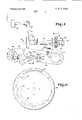
- FIG. Iis a perspective view of a machine embodying the invention.
- FIG. 2is a plan view showing a portion of the specimen and test conveyor and the apparatus located therebetween;
- FIG. 3is a horizontal section of the specimen conveyor
- FIG. 4is a vertical section taken along the line 44 of FIG. 3;
- FIG. 5is a diagrammatic representation showing the specimen conveyor cooling channel
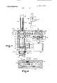
- FIG. 6is a diagrammatic showing of a driving cam for the specimen and test chemistry conveyors
- FIG. 7is a vertical view, in partial section, of a por tion of the sample transfer apparatus
- FIG. 8is a vertical section taken along the line 8-8 of FIG. 7;
- FIG. 9is a vertical section showing the serum pickup valve apparatus used in conjunction with the transfer apparatus of FIG. 7;
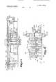
- FIG. 10is a horizontal section of the test conveyor
- FIG. Iis a sectional view taken along line llll of FIG. 10;
- FIG. I2is a vertical section of a combined dispensing and mixing head
- FIG. 13is a plan view of a reagent selector apparatus and associated dispensing valves
- FIG. I4is a vertical section along line l4l4 of FIG. I3;
- FIG. I5is a vertical section along line ]5IS of FIG. [3;
- FIG. 16is a diagrammatic representation of the tem perature control apparatus for the test chemistry conveyor
- FIG. 17is a vertical section partially diagrammatic, of the test chemistry extraction apparatus and spectrophotometer flow cell
- FIG. 18is a vertical section of the spectrophotometer flow cell reciprocating apparatus
- FIG. 19is a vertical view, partially in section, of an alternate embodiment of the sample transfer apparatus.
- FIG. 20is a side view partially in section, of an alternate embodiment of the serum pickup valve apparatus
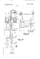
- FIG. 21is an enlarged section of the orifieing tube assembly utilized in the valve apparatus of FIG. 20;
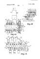
- FIG. 22is a vertical view, in section, of an alternate embodiment of the combined dispensing and mixing head
- FIG. 23is a plan view, partially in section of an alternate embodiment of the reagent selection apparatus and dispensing valves
- FIG. 24is a side view partially in section, of the apparatus valves shown in FIG. 23;
- FIG. 25is a section of one of the valving units shown in FIG. 23, with portions thereof broken away;
- FIG. 26is a vertical section of an alternative embodiment of the test chemistry extraction apparatus.
- the chemical analyzation machine shown in the drawingsis for the serial analyzation of serum specimens which have been obtained from respective patients by conventional means.
- serumis used herein in the sense of representing any animal fluid.
- the electronic logic control which controls the operation of this machineis shown and described in a co-pending application, U.S. Ser. No. l79,l33. now abandoned.
- the machine shown in FIG. Iand which is a preferred embodiment of the invention. comprises an upper housing I0 supported on a lower housing 12 by a post 14.
- a serum specimen conveying wheel 16 and a test chemistry conveying wheel 18are supported in and by the top of the lower housing 12.
- the drive motor for these wheelsis located within the lower housing I2.
- the bottom portion of the lower housing 12encloses an array of pressurized bottles 20, some of which are enclosed in a refrigerated compartment 22.
- These bottles 20contain the various chemical reagents used in the performance ofa serum analysis by the machine. They are desirably pressurized with inert nitrogen gas to prevent degradation of the reagents.
- Dark transparent doors 23 on the front of the lower housing 12permit the bottle compartment to be observed while reducing reagent degradation due to light.
- a serum transfer apparatus 24, a plurality ofdispensing heads 26, 27 and 28, and a test chemistry extraction head 29are, as shown in FIG. 3. located in close proximity to the serum specimen wheel I6 and the test chemistry wheel I8.
- Serum specimens from which samples are taken during the analysis procedure for test samples.are placed in a plurality of specimen cups 30 which are carried in equally-spaced cavities 3] in the top of the specimen conveying wheel I6. Each of the cavities is numbered and has a patient-identification selection switch 108 associated with it.
- test tubes 33are carried in equally-spaced peripheral holes 34 in the test chemistry conveying wheel 18.
- a serum sample in a position I26 to be transferredis appropriately taken from its specimen cup 30 in the specimen wheel 16 and transferred to a test tube 33 waiting in a transfer position 127 in the test wheel 18, by the serum sample transfer apparatus 24.
- the portion of the sample transfer apparatus 24 which transfers the samplecan be washed by jets of air and water as it passes Over a basin-like cavity 296 on its return trip to the sample wheel 16.
- Properly selected reagentsare added by means of the dispensing heads 26, 27 and 28 to each of the serum samples which have been transferred to test tubes 33 as the test wheel 18 is indexed through the dispensing stations.
- the test chemistries thereby formulatedare then serially extracted for subsequent optical analyzation, as in a spectrophotometer or fluorometer, by the test chemistry extraction head 29.
- the spectrophotometer or fluorometermay be housed within the supporting post 14.
- the electronic logic control circuitry for controlling each of the operationsis contained in the upper housing 10. This circuitry may be programmed by a specially prepared card which is inserted in a slot 36 lead ing to a card reader (not shown). also supported in and by the upper housing II). An array of actuation buttons 38 may be located adjacent the card reader slot 36 for manually controlling a part or all of the machine operations. Electronic circuitry, which may also be located in the upper housing I0, can be used to convert the output signals from the spectrophotometer or like device into more usable forms of data such as international enzyme units or milligram percentage concentrations by automatically comparing the spectrophotometer output from the test chemistry with the output from a standard solution whose concentration is known.
- the serum specimen wheel 16is shown in FIGS. 3 through 6 and is comprised of a stationary lower base plate and a rotating top disk 52.
- the specimen vials, or cups 30,are placed in holes 31 located adjacent to the outer edge of the rotating top disk 52 of the specimen wheel I6.
- Each of the cups 30is retained in its receiving cavity 31 by a lip 56 around its upper edge.
- the cups 30extend through the top supporting disk 52 and into a channel 58 formed by a circular channel member 60 which is fastened to the base plate 50 of the speci men wheel 16.
- the serum specimens in the cups 30are advantageously cooled as they travel within the specimen wheel channel 58 by cool air which is forced into the channel 58 from the refrigeration compartment 22.
- cool airis forced through an inlet 62 into an entrance channel 64.
- This channel 64opens into the cup channel 58, so that part of the air goes in a clockwise direction and part of the air goes in a counterclockwise direction.
- the airproceeds for in both directions and leaves the channel 58 by an outlet port 66.
- the cup-carrying top disk 52is rotatably driven by a driving pin plate 68 connected to its lower surface as by pins 70.
- the plate 68is also attached to a central shaft 72 which is mounted in bearing blocks 74 and 76 in a cylindrical supporting member 78 connected to and extending from the base plate 50.
- the lower end of the shaft 72is supported in a hub 80 by a thrust washer 82 and is held in place by a nut 84.
- the driving pin plate 68is driven by a barrel cam 86.
- This cam 86is mounted on a shaft 88 which is supported in a bearing block 90 which is mounted in a supporting bracket 92 that is fastened to the base plate 50 f the specimen wheel 16.
- the cam driving shaft 88is driven through a conventional one-half turn clutch 94 from a drive pulley 96 which turns a pulley gear 102 mounted on the clutch 94.
- the pulley 96is driven from a motor 98 which drives a second pulley gear 100 on which the drive pulley 96 is mounted.
- a solenoid(not shown) is energized to engage the clutch 94 and permit the cam drive shaft 88 to rotate.
- This solenoidmay be de-energized once the clutch has begun to rotate to effect only a 180 rotation of the shaft 88 and cam 86.
- the shaft 88 and cam 86may be rotated indefinitely if the solenoid is held in a continu ously energized state.
- the configuration of the two sets of tracks in the cam 86is shown in P16. 6.
- a 180 rotation of the camcorre sponds to the advancement of one cup position by each of the serum cups 30.
- the cup-carrying disk 52will have a capacity of one hundred serum cups, and thus the advancing of the equally-spaced cups 30 by one cup position means that the wheel 16 has been moved through an angle of 3.6".
- the driving pin plate 68has a driving pin 106 for each of the test cup holes 54.
- the double lead in the barrel cam 86allows two such pins to be in communication with the barrel cam even though only one pin is driven at a time.
- the barrel camis rotatably driving the pin-driving plate 68 during only a fraction of its total revolution due to the configuration of the barrel cam 86. This places the control of the indexing step with the barrel cam 86, rather than making it dependent upon the accuracy of the one-half turn clutch 94. This independence of control avoids any problems with an accumulated positioning error which may be incurred by the clutch 94.
- a serum specimen from each patient to be testedis placed in one of the serum cups 30.
- each of the serum specimenswill not be meant to receive all of the tests which may be performed in a series of tests. For example, perhaps only the specimens in cups and are to receive an albumin test, but possibly all the specimens in the specimen wheel 16 are to receive a subsequent test for cholesterol content.
- the selection of the particular serum specimens which are to receive a particular testis made by the respective patientidentification slide switches 108 which are associated with each of the serum cups 30. In the above example, the switches 108 adjacent cups and 10 would be displaced, moved to a control position, prior to the albumin test to signify that the serum in those cups is to receive a test for albumin content. At the conclusion of the albumin test, the paticntidentification switches 108 associated with all of the serum specimens would be displaced for the cholesterol content test.
- a test start button 109 on the front of the machine(FIG. 1 is pressed to initiate a testing cycle after the program card has been inserted and the proper patientidentification buttons 108 corresponding to the serum samples which are to receive that particular test have been displaced.
- the clutch solenoidis energized to begin the rotation of the driving cam 86.
- the one-half turn clutch 94continues to be engaged until a displaced patient-identification button 108 is detected by a sensing device 110 beneath the rotating disk 52.
- the sensing device 110comprises an L-shaped member 112 which is connected to a spring loaded deflection arm 114. The arm 114 is moved to compress a spring 116 when the L-shaped member 112 is deflectcd by a patient identification button 108 which has been pushed to a displaced, control position.
- the movement of the arm 114also positions an aper ture 118 in an otherwise optically black plate 120 between a light source 122 and a photocell 124.
- the resulting electrical signal from the photocell 124is de tected by the control logic which de-energizes the clutch solenoid (not shown) and thereby halts the rotation of the pin-driving cam 86.
- the patientidentification detection device 110is located so that a depressed button 108 is detected as the corresponding serum cup enters the transfer station 126.
- This station or cup position 126is defined as being one cup position removed from the home position 129 of the number one cup which is adjacent the sample or serum transfer apparatus 24.
- a light source 132 and a photocell 134are positioned such that each time the disk 128 rotates 180 one of the holes 130 or 131 permits a pulse of light to fall on the photocell 134.
- the electrical pulse generated by the photocell 134is stored in the electronic logic section and permits the particular serum cup 30 in the transfer station 126 to be identified at any time.
- the signal from the photocell 124 in the patient-identification button detection device 110is also stored in the electronic logic section as a means of identifying the particular serum specimens which were sampled.
- the stopping of a specimen cup 30 in the transfer position 126initiates the movement and operation of the serum pickup and transfer apparatus 24.
- This apparatus 24one embodiment of which is shown in detail in FIGS. 7 through 9, is supported in, and projects vertically from, the top of the lower machine housing 12.
- the portion of the transfer mechanism 24 which is located above the level of the test wheel 18is comprised, in general, of a horizontal swingable arm which is supported on a shaft 142.
- the shaft 142is enclosed by a tubular support member 144 which is fastened to the underside of the top 147 of the lower housing 12 by a flange 146 on its lower end.
- the enclosed shaft 142is connected to a spline shaft 148 within the tubular support 144.
- the spline shaft 148is connected at its lower end to a coupling block 150 for coupling the piston shaft 152 of an air cylinder 154 to the spline shaft 148.
- This cylinder 154is supplied with a pressurized gas for purposes of pneumatic actuation. This is referred to herein as an air cylinder" even though this embodiment conveniently uses compressed nitrogcn which is available from the supply for the pressurization of the reagent bottles 20. All the remaining air cylinders in the system also utilize this supply.
- the piston shaft 152extends through a spring extension plate 156 and through a bottom supporting bracket 158 before entering the air cylinder 154.
- shaft 152is attached at its lower end. within the cylinder 154. to a rollable membrance or diaphragm 160.
- the diaphragm 160separates the air cylinder 154 into an inlet section 162 and an exhaust section 164 and seals the one from the other.
- Air or other gas as referred to above.is applied, under pressure, to the inlet section 162 through an inlet port 166 to cause the diaphragm 160 to roll downwardly into the solid line position shown in FIG. 7.
- the piston shaft 152is moved downward due to its fixed connection to the diaphragm 160.
- the downward movement of the piston shaft 152is transferred by the coupling block 150 to the spline shaft 148 and to the spring extension plate 156 which the coupling block 150 contacts as it moves downward.
- Two springs 168 and 170are each connected at their lower end to the spring extension plate 156.
- the springs 168 and 170are respectively supported on and encompass a shaft 172 and 174 which passes through the extension plate 156 and is mounted in the bottom supporting bracket 158.
- the upper ends of the springs 168 and 170are connected to end plates 176 and 178 which are mounted on the ends of the shafts 172 and 174.
- the springs 168 and 170are extended by the downward movement of the extension plate 156 and oppose this movement.
- the spline shaft 148may be rotatably driven, concurrently with its up and down movement, from a servo stepping motor 180 by wear resistant pulley bands 194 and 196 which are connected to a spline nut 184 on the shaft 148.
- the spline nut 184is mounted by means of bearings 186 and 188 in a nut housing 190 which is mounted on a side bracket 192.
- Positive rotary driveis supplied to the spline nut 184 by the pulley bands 194 and 196 from a motor-driven pulley 198 around which the bands 194 and 196 pass.
- the shaft 200 for this pulley 198is mounted in a bearing block 202 at is upper end. lts lower end is reduced in diameter and is supported in. and extends through, another bearing block 204 and a bracket 206 which supports the pulley 198.
- This bracket 206is mounted on the lower sidc of the top 147 of the lower machine housing 12.
- the pulley shaft 200is terminated in a shock absorbing coupling 208, and is connected thereby to the servo stepping motor 180.
- An optical position detection disk 210is mounted on the shock coupling 208 concentrically with the pulley shaft 200.
- This disk 210has two holes through it at diametrically opposed locations. The holes are positioned such that one of them is between a light source 212 and a photocell 214 when the horizontal serum transfer arm 140 is above the test chemistry wheel 18 and the other when the arm 140 is above the specimen wheel 16.
- the resulting electrical signal from the photocell 214is used to synchronize the up and down motion of the transfer apparatus with the dispensing and pick up of a serum sample.
- the band drive system for the spline nut 184is shown in somewhat more detail in FIG. 8.
- the pulley bands 194are preferably comprised of a material with extreme longevity. cg. a composition of beryllium and copper.
- One end of each of the bands 194 and 196is attached to the spline nut 184 and passes around the motor pulley 198 before being attached to a springloaded tensioning device 216.
- the spanning length of each of the bands, from the spline nut 184 to the motor pulley 198,can be interrupted by a second tensioning device 218. Where appropriate, the second tensioning device 218 can be omitted.
- the tcnsioning devices 216 and 218comprise a spring 220 which is compressed by retaining shoulders 222 and 224. These shoulders 222 and 224 form part of connecting tabs 225 to which the ends of the bands 194 and 196 are connected.
- the single-ended tensioning device 216has one end fixedly connected to the frame of the apparatus.
- the position for the horizontal transfer arm at the beginning of a serum testing procedure.is above the test chemistry wheel 18. Movement of the arm 140 from this position is initiated by a signal from the patient-identification switch detection photocell 124 beneath the specimen wheel 16 signifying that a serum cup 30 containing a serum specimen to be tested, has arrived at the transfer position 126.
- the elect onic logic controlbegins pulsing the servo stepping motor 180.
- the motor 180turns the motor pulley 198 through the shock absorbing coupling 208, which in turn begins rotating the spline nut 184 by means of the driving bands 194 and 196.
- the tension ing devices 216 and 218 controlling the bands 194 and 196absorb the pulsing characteristic of the stepping motor 180 so that the spline nut 194 is smoothly rotated.
- One of the holes on the optical transfer arm position detection disk 210is positioned, as hereinbefore explained, between a light source 212 and a photocell 214 as the horizontal transfer arm 140 finishes its 180 swing to position itself above the specimen cup 30 in the transfer position 126.
- the resulting electrical pulse from the photocell 214opens a pressurization valve 221 leading from the pressurized air supply to the inlet port 166 of the up and down air cylinder 154.
- the resulting gas pressure in the inlet section 162 of the cylinder 154causes the diaphragm 160 to move downward taking the piston shaft 152 with it.
- the rolling action of the diaphragm 160eliminates the need for any breakaway force, so the motion of the shaft 152 is initially and continually smooth.
- the coupling block associated with the piston shaft 152is thereby forced downward onto the spring extension plate 156 as it simultaneously moves the spline shaft 148 downward.
- the spline shaft 148is able to move downward by means of ball bearings within the spline nut 184.
- the movement of the spline shaft 148causes the horizontal arm 140 to move downward also. This downward travel of the arm 140 continues until a resilient and compressible stopper 222, which protrudes from the lower side of the arm 140, firmly seals itself against the top of a waiting serum cup 30.
- a bracket 226is connected to the spring extension plate 156 on the air cylinder piston shaft 152 and moves up and down with this shaft.
- Two vertical position optical detection arms 228 and 230are connected to this bracket 226 and move up and down therewith. Each of these arms 228 and 230 has a hole through it which provides a light path from a light source to a photocell when the arm is in the appropriate position.
- the upper arm 228has its hole in communication with a photocell 232 and a light source 234 when the horizontal transfer arm 140 is in its uppermost vertical posi tion.
- the hole in the lower arm 230is in communica tion with a light source 236 and a photocell (not shown) when the horizontal transfer arm 140 is in its lower-most vertical position, i.e., when the resilient stopper 222 has sealed a sample cup 30.
- the lower end of the flexible tube 244 which is connected to the shorter stainless steel tube 242 in the stopper 222is connected to the outlet of a pressurization valve (not shown).
- the inlet of this valveis connected to the pressurized air supply, preferably maintained at a pressure of approximately psi.
- the lower end of the other flexible tube 246, coupled to the longer stainless steel tube 240 in the stopper 222,is connected to a valve assembly 250 by inserting the tube into a tubular supporting member 252 which contains a glass capillary tube 254 which projects up into the tube 246.
- a tapered and threaded locking member 256is then tightened about a similarly tapered member 258 causing the latter to tighten about the inserted flexible tube 246 and form an air-tight seal.
- the glass capillary tube 254extends down into the main valve block 260 and terminates in a perpendicular intersection with a second glass tube 262. Each side of this intersecting glass tube 262 is enlarged in diameter a short distance from its intersection with the vertical tube 254. Within each of these enlarged diameter tubes 264 and 266 is a piston-operated valve plunger 268 and 270. Each of these plungers 268 and 270 is terminated at its forward end by a small resilient washer 272 and 274, respectively. which firmly seats itself against the constricted passageway 262 at the respective end to seal that end from the passageway.
- each of these valving members 268 and 270is controlled, respectively, by a piston 273 and 275.
- the pistons 273 and 275 and 274are rapidly moved by respective solenoids 280 and 282.
- Each of the piston arms 276 and 278is supported within the valve block 260 by Orings 284 and 286 which not only prevent leakage from the valve block but help guide the piston arms 276 and 278 and prevent them from being skewed within their passageways.
- Vertical passages 288 and 290intersect and open into each of the valved passages 264 and 266 just behind each of the valve plungcrs 268 and 270. These vertical passages 288 and 290 communicate with the narrow cross passage 262 and thereby with the vertical orificcd capillary tube 254 when the appropriate valving member 268 and 270 is in its retracted position.
- One of these vertical passages 288is connected by a connector 292 in the valve block 260 to a waste receptacle (not shown).
- the other vertical passage 290is connected by a similar connector 294 in the valve block 260 to a pressurized water supply which is prefe rably maintained at a pressure of approximately ll) pounds per square inch.
- both of the solenoid piston arms 276 and 278are in their extended position. thereby closing off the respective passages 288 and 290.
- the transfer armhas been rotated and has descended, seating the resilient stopper 222 on the waiting specimen cup 224.
- the descent and final positioning of the transfer arm 140positions the hole in the lower optical position arm 230 between the light source 236 and the corresponding photocell.
- the resulting electrical pulse from the photocellopens the pressurization valve leading from the pressurized gas or air supply to the short tube 242 in the resilient stopper 222.
- the resulting flow of gaspressurizes the contents of the cup 30.
- the logicShortly after the electronic logic detects the presence of an output from the lower position photocell 236, the logic energizes the sample pickup solenoid 280 which withdraws its connected valving member 268. This withdrawal places the passage 288 leading to the waste receptacle in communication with the long stainless steel tube 240 which has its end submerged in the serum sample in the serum cup 30. The pressure in the cup 30 induces and sustains a flow of serum into this tube 240 as long as the pick-up solenoid 280 is ener gized.
- This pickup solenoid 280is deenergized and re extends its valving member 268 when the programmed amount of serum has been extracted from the specimen cup 30.
- the steel extraction tube 240 and the supply tube 246 to which it is connectedis initially filled with water.
- the signal from the control logic which tile-energizes the pick-up solenoid 280 and terminates the extraction of the serum samplealso de-energizes the pressurization air valve connected to the short tube 242 and allows the built-up pressure to vent into the atmosphere.
- the air valve 221 which has been supplying the air cylinder 154 to hold the transfer arm 140 down and the resilient stopper 222 on the sample cup 30is subse quently de-energized.
- the two extension springs 168 and 170 acting on the extension plate 156are then no longer maintained in their extended position by air pressure, so they cause the plate 156 to move upwards, thereby forcing the coupling block 150 and spline shaft 148 to move upward also.
- the upward movementis buffered to some extent by the air or gas in the inlet chamber 162 of the air cylinder 154 as it is then compressed by the upward moving diaphragm [60 to slowly escape through inlet 166. lt can be seen that this upward movement also moves the hole in the position de tection arm 230 out of communication with its light source 236 and associated photocell so that the photocell no longer conducts.
- the electronic logicnotes the absence of this photocell output and once again begins pulsing the servo stepping motor to rotate the transfer arm 140 through l8(), back to its position above the test chemistry wheel.
Landscapes
- Chemical & Material Sciences (AREA)
- Chemical Kinetics & Catalysis (AREA)
- Physics & Mathematics (AREA)
- Health & Medical Sciences (AREA)
- Life Sciences & Earth Sciences (AREA)
- Analytical Chemistry (AREA)
- Biochemistry (AREA)
- General Health & Medical Sciences (AREA)
- General Physics & Mathematics (AREA)
- Immunology (AREA)
- Pathology (AREA)
- Investigating Or Analysing Biological Materials (AREA)
- Automatic Analysis And Handling Materials Therefor (AREA)
Abstract
Description
Claims (42)
Priority Applications (1)
| Application Number | Priority Date | Filing Date | Title |
|---|---|---|---|
| US452728AUS3901656A (en) | 1972-08-24 | 1974-03-20 | Apparatus and method for preparing and presenting serum chemistries for analyzation |
Applications Claiming Priority (2)
| Application Number | Priority Date | Filing Date | Title |
|---|---|---|---|
| US28341572A | 1972-08-24 | 1972-08-24 | |
| US452728AUS3901656A (en) | 1972-08-24 | 1974-03-20 | Apparatus and method for preparing and presenting serum chemistries for analyzation |
Publications (1)
| Publication Number | Publication Date |
|---|---|
| US3901656Atrue US3901656A (en) | 1975-08-26 |
Family
ID=26962033
Family Applications (1)
| Application Number | Title | Priority Date | Filing Date |
|---|---|---|---|
| US452728AExpired - LifetimeUS3901656A (en) | 1972-08-24 | 1974-03-20 | Apparatus and method for preparing and presenting serum chemistries for analyzation |
Country Status (1)
| Country | Link |
|---|---|
| US (1) | US3901656A (en) |
Cited By (73)
| Publication number | Priority date | Publication date | Assignee | Title |
|---|---|---|---|---|
| US4169125A (en)* | 1977-04-14 | 1979-09-25 | Baxter Travenol Laboratories, Inc. | Modular chemical analysis system |
| FR2474697A1 (en)* | 1980-01-28 | 1981-07-31 | Coulter Electronics | MULTI-POSITION FLUID TRANSFER MECHANISM |
| EP0041378A1 (en)* | 1980-05-30 | 1981-12-09 | Hitachi, Ltd. | Automatic analytical instrument |
| US4554436A (en)* | 1984-03-15 | 1985-11-19 | Bodenseewerk Perkin-Elmer & Co., Gmbh | Electric heater for a rotating sample vessel container in a sampling device for gas chromatography |
| US4615866A (en)* | 1984-07-27 | 1986-10-07 | American Monitor Corporation | Fluid-sampling system and method |
| US4669878A (en)* | 1984-06-29 | 1987-06-02 | American Monitor Corporation | Automatic monochromator-testing system |
| US4818706A (en)* | 1983-04-19 | 1989-04-04 | American Monitor Corporation | Reagent-dispensing system and method |
| US5380486A (en)* | 1991-04-19 | 1995-01-10 | Olympus Optical Co., Ltd. | Apparatus for taking liquid content for use in analysis out of container |
| US5525298A (en)* | 1991-04-19 | 1996-06-11 | Olympus Optical Co., Ltd. | Apparatus for taking liquid content for use in analysis out of container |
| US5580541A (en)* | 1991-05-01 | 1996-12-03 | Mallinkrodt Medical, Inc. | Method of conveying liquid materials and device for the automated elution of a radionuclidic generator |
| US5585068A (en)* | 1990-02-20 | 1996-12-17 | Biochemical Diagnostics, Inc. | Apparatus for automatically separating a compound from a plurality of discrete liquid specimens |
| US5670114A (en)* | 1995-03-08 | 1997-09-23 | Hitachi, Ltd. | Apparatus of handling reagent for suppressing decrease in effect of reagent |
| US5766352A (en)* | 1996-01-11 | 1998-06-16 | Kuntz Mfg. Co., Inc. | Stripe applicator device |
| US20020044894A1 (en)* | 1999-12-13 | 2002-04-18 | Michal Lebl | Oligonucleotide synthesizer |
| US20050232816A1 (en)* | 2004-04-20 | 2005-10-20 | Akribio Corp. | Multiport cofinger microreactor stopper and device |
| US20110076774A1 (en)* | 2009-09-30 | 2011-03-31 | Sysmex Corporation | Sample analyzer and sample analyzing method |
| US20130259745A1 (en)* | 2010-10-27 | 2013-10-03 | Isao Yamazaki | Automatic analyzer |
| US9001319B2 (en) | 2012-05-04 | 2015-04-07 | Ecolab Usa Inc. | Self-cleaning optical sensor |
| US9140648B2 (en) | 2013-03-12 | 2015-09-22 | Ecolab Usa Inc. | Fluorometer with multiple detection channels |
| US9423411B2 (en) | 2014-02-17 | 2016-08-23 | Roche Diagnostics Operations, Inc. | Transport device, sample distribution system and laboratory automation system |
| US9423410B2 (en) | 2014-02-17 | 2016-08-23 | Roche Diagnostics Operations, Inc. | Transport device, sample distribution system, and laboratory automation system |
| US9567167B2 (en) | 2014-06-17 | 2017-02-14 | Roche Diagnostics Operations, Inc. | Laboratory sample distribution system and laboratory automation system |
| US9575086B2 (en) | 2011-11-04 | 2017-02-21 | Roche Diagnostics Operations, Inc. | Laboratory sample distribution system, laboratory system and method of operating |
| US9593970B2 (en) | 2014-09-09 | 2017-03-14 | Roche Diagnostics Operations, Inc. | Laboratory sample distribution system and method for calibrating magnetic sensors |
| US9598243B2 (en) | 2011-11-04 | 2017-03-21 | Roche Diagnostics Operations, Inc. | Laboratory sample distribution system and corresponding method of operation |
| US9604186B1 (en)* | 2012-05-01 | 2017-03-28 | Dow Agrosciences Llc | Automated multichannel media dispenser |
| US9618525B2 (en) | 2014-10-07 | 2017-04-11 | Roche Diagnostics Operations, Inc. | Module for a laboratory sample distribution system, laboratory sample distribution system and laboratory automation system |
| US9658241B2 (en) | 2014-03-31 | 2017-05-23 | Roche Diagnostics Operations, Inc. | Sample distribution system and laboratory automation system |
| US9664703B2 (en) | 2011-11-04 | 2017-05-30 | Roche Diagnostics Operations, Inc. | Laboratory sample distribution system and corresponding method of operation |
| US9772342B2 (en) | 2014-03-31 | 2017-09-26 | Roche Diagnostics Operations, Inc. | Dispatching device, sample distribution system and laboratory automation system |
| US9791468B2 (en) | 2014-03-31 | 2017-10-17 | Roche Diagnostics Operations, Inc. | Transport device, sample distribution system and laboratory automation system |
| US9810706B2 (en) | 2014-03-31 | 2017-11-07 | Roche Diagnostics Operations, Inc. | Vertical conveying device, laboratory sample distribution system and laboratory automation system |
| US9902572B2 (en) | 2015-10-06 | 2018-02-27 | Roche Diagnostics Operations, Inc. | Method of configuring a laboratory automation system, laboratory sample distribution system and laboratory automation system |
| US9939455B2 (en) | 2014-11-03 | 2018-04-10 | Roche Diagnostics Operations, Inc. | Laboratory sample distribution system and laboratory automation system |
| US9952242B2 (en) | 2014-09-12 | 2018-04-24 | Roche Diagnostics Operations, Inc. | Laboratory sample distribution system and laboratory automation system |
| US9969570B2 (en) | 2010-05-07 | 2018-05-15 | Roche Diagnostics Operations, Inc. | System for transporting containers between different stations and a container carrier |
| US9989547B2 (en) | 2014-07-24 | 2018-06-05 | Roche Diagnostics Operations, Inc. | Laboratory sample distribution system and laboratory automation system |
| US10006927B2 (en) | 2015-05-22 | 2018-06-26 | Roche Diagnostics Operations, Inc. | Method of operating a laboratory automation system and a laboratory automation system |
| US10012666B2 (en) | 2014-03-31 | 2018-07-03 | Roche Diagnostics Operations, Inc. | Sample distribution system and laboratory automation system |
| US10094843B2 (en) | 2015-03-23 | 2018-10-09 | Roche Diagnostics Operations, Inc. | Laboratory sample distribution system and laboratory automation system |
| US10119982B2 (en) | 2015-03-16 | 2018-11-06 | Roche Diagnostics Operations, Inc. | Transport carrier, laboratory cargo distribution system, and laboratory automation system |
| US10160609B2 (en) | 2015-10-13 | 2018-12-25 | Roche Diagnostics Operations, Inc. | Laboratory sample distribution system and laboratory automation system |
| US10175259B2 (en) | 2015-09-01 | 2019-01-08 | Roche Diagnostics Operations, Inc. | Laboratory cargo distribution system, laboratory automation system and method of operating a laboratory cargo distribution system |
| US10197555B2 (en) | 2016-06-21 | 2019-02-05 | Roche Diagnostics Operations, Inc. | Method of setting a handover position and laboratory automation system |
| US10197586B2 (en) | 2015-10-06 | 2019-02-05 | Roche Diagnostics Operations, Inc. | Method of determining a handover position and laboratory automation system |
| US10228384B2 (en) | 2015-10-14 | 2019-03-12 | Roche Diagnostics Operations, Inc. | Method of rotating a sample container carrier, laboratory sample distribution system and laboratory automation system |
| US10239708B2 (en) | 2014-09-09 | 2019-03-26 | Roche Diagnostics Operations, Inc. | Laboratory sample distribution system and laboratory automation system |
| US10352953B2 (en) | 2015-05-22 | 2019-07-16 | Roche Diagnostics Operations, Inc. | Method of operating a laboratory sample distribution system, laboratory sample distribution system and a laboratory automation system |
| US10416183B2 (en) | 2016-12-01 | 2019-09-17 | Roche Diagnostics Operations, Inc. | Laboratory sample distribution system and laboratory automation system |
| US10436808B2 (en) | 2016-12-29 | 2019-10-08 | Roche Diagnostics Operations, Inc. | Laboratory sample distribution system and laboratory automation system |
| US10495657B2 (en) | 2017-01-31 | 2019-12-03 | Roche Diagnostics Operations, Inc. | Laboratory sample distribution system and laboratory automation system |
| US10509049B2 (en) | 2014-09-15 | 2019-12-17 | Roche Diagnostics Operations, Inc. | Method of operating a laboratory sample distribution system, laboratory sample distribution system and laboratory automation system |
| US10520520B2 (en) | 2016-02-26 | 2019-12-31 | Roche Diagnostics Operations, Inc. | Transport device with base plate modules |
| US10564170B2 (en) | 2015-07-22 | 2020-02-18 | Roche Diagnostics Operations, Inc. | Sample container carrier, laboratory sample distribution system and laboratory automation system |
| US10578632B2 (en) | 2016-02-26 | 2020-03-03 | Roche Diagnostics Operations, Inc. | Transport device unit for a laboratory sample distribution system |
| US10605819B2 (en) | 2016-02-26 | 2020-03-31 | Roche Diagnostics Operations, Inc. | Transport device having a tiled driving surface |
| US10962557B2 (en) | 2017-07-13 | 2021-03-30 | Roche Diagnostics Operations, Inc. | Method of operating a laboratory sample distribution system, laboratory sample distribution system and laboratory automation system |
| US10989726B2 (en) | 2016-06-09 | 2021-04-27 | Roche Diagnostics Operations, Inc. | Laboratory sample distribution system and method of operating a laboratory sample distribution system |
| US10989725B2 (en) | 2017-06-02 | 2021-04-27 | Roche Diagnostics Operations, Inc. | Method of operating a laboratory sample distribution system, laboratory sample distribution system, and laboratory automation system |
| US10996233B2 (en) | 2016-06-03 | 2021-05-04 | Roche Diagnostics Operations, Inc. | Laboratory sample distribution system and laboratory automation system |
| US11092613B2 (en) | 2015-05-22 | 2021-08-17 | Roche Diagnostics Operations, Inc. | Method of operating a laboratory sample distribution system, laboratory sample distribution system and laboratory automation system |
| US11112421B2 (en) | 2016-08-04 | 2021-09-07 | Roche Diagnostics Operations, Inc. | Laboratory sample distribution system and laboratory automation system |
| US11110464B2 (en) | 2017-09-13 | 2021-09-07 | Roche Diagnostics Operations, Inc. | Sample container carrier, laboratory sample distribution system and laboratory automation system |
| US11110463B2 (en) | 2017-09-13 | 2021-09-07 | Roche Diagnostics Operations, Inc. | Sample container carrier, laboratory sample distribution system and laboratory automation system |
| US11204361B2 (en) | 2017-02-03 | 2021-12-21 | Roche Diagnostics Operations, Inc. | Laboratory automation system |
| US20220011229A1 (en)* | 2020-07-13 | 2022-01-13 | Buckman Laboratories International, Inc. | Fluorometer calibration device and method |
| US11226348B2 (en) | 2015-07-02 | 2022-01-18 | Roche Diagnostics Operations, Inc. | Storage module, method of operating a laboratory automation system and laboratory automation system |
| US11709171B2 (en) | 2018-03-16 | 2023-07-25 | Roche Diagnostics Operations, Inc. | Laboratory system, laboratory sample distribution system and laboratory automation system |
| US11747356B2 (en) | 2020-12-21 | 2023-09-05 | Roche Diagnostics Operations, Inc. | Support element for a modular transport plane, modular transport plane, and laboratory distribution system |
| US11971420B2 (en) | 2018-03-07 | 2024-04-30 | Roche Diagnostics Operations, Inc. | Method of operating a laboratory sample distribution system, laboratory sample distribution system and laboratory automation system |
| US12000851B2 (en) | 2020-07-15 | 2024-06-04 | Roche Diagnostics Operations, Inc. | Laboratory sample distribution system and method for operating the same |
| US12000850B2 (en) | 2020-06-19 | 2024-06-04 | Roche Diagnostics Operations, Inc. | Laboratory sample distribution system and corresponding method of operation |
| US12429491B2 (en) | 2020-11-23 | 2025-09-30 | Roche Diagnostics Operations, Inc. | Laboratory sample distribution system and laboratory automation system |
Citations (9)
| Publication number | Priority date | Publication date | Assignee | Title |
|---|---|---|---|---|
| US3193358A (en)* | 1962-07-02 | 1965-07-06 | Warner Lambert Pharmacentical | Automated analytical apparatus |
| US3202188A (en)* | 1961-10-23 | 1965-08-24 | Instrumentation Specialties Co | Apparatus for making chemical separations |
| US3489521A (en)* | 1965-04-14 | 1970-01-13 | Vickers Ltd | Automatic laboratory |
| US3508879A (en)* | 1966-12-15 | 1970-04-28 | Xerox Corp | Aliquotting device |
| US3574064A (en)* | 1968-05-09 | 1971-04-06 | Aerojet General Co | Automated biological reaction instrument |
| US3589867A (en)* | 1967-06-24 | 1971-06-29 | Bodenseewerk Perkin Elmer Co | Method and apparatus for automatically carrying out chemical analysis |
| US3660638A (en)* | 1969-08-28 | 1972-05-02 | Rudolf Oberli | Automatic analyzing apparatus for liquid specimens |
| US3698870A (en)* | 1971-03-02 | 1972-10-17 | Technicon Instr | Apparatus for pumping with viscosity control |
| US3725010A (en)* | 1971-08-23 | 1973-04-03 | Beckman Instruments Inc | Apparatus for automatically performing chemical processes |
- 1974
- 1974-03-20USUS452728Apatent/US3901656A/ennot_activeExpired - Lifetime
Patent Citations (9)
| Publication number | Priority date | Publication date | Assignee | Title |
|---|---|---|---|---|
| US3202188A (en)* | 1961-10-23 | 1965-08-24 | Instrumentation Specialties Co | Apparatus for making chemical separations |
| US3193358A (en)* | 1962-07-02 | 1965-07-06 | Warner Lambert Pharmacentical | Automated analytical apparatus |
| US3489521A (en)* | 1965-04-14 | 1970-01-13 | Vickers Ltd | Automatic laboratory |
| US3508879A (en)* | 1966-12-15 | 1970-04-28 | Xerox Corp | Aliquotting device |
| US3589867A (en)* | 1967-06-24 | 1971-06-29 | Bodenseewerk Perkin Elmer Co | Method and apparatus for automatically carrying out chemical analysis |
| US3574064A (en)* | 1968-05-09 | 1971-04-06 | Aerojet General Co | Automated biological reaction instrument |
| US3660638A (en)* | 1969-08-28 | 1972-05-02 | Rudolf Oberli | Automatic analyzing apparatus for liquid specimens |
| US3698870A (en)* | 1971-03-02 | 1972-10-17 | Technicon Instr | Apparatus for pumping with viscosity control |
| US3725010A (en)* | 1971-08-23 | 1973-04-03 | Beckman Instruments Inc | Apparatus for automatically performing chemical processes |
Cited By (87)
| Publication number | Priority date | Publication date | Assignee | Title |
|---|---|---|---|---|
| US4169125A (en)* | 1977-04-14 | 1979-09-25 | Baxter Travenol Laboratories, Inc. | Modular chemical analysis system |
| FR2474697A1 (en)* | 1980-01-28 | 1981-07-31 | Coulter Electronics | MULTI-POSITION FLUID TRANSFER MECHANISM |
| EP0041378A1 (en)* | 1980-05-30 | 1981-12-09 | Hitachi, Ltd. | Automatic analytical instrument |
| US4818706A (en)* | 1983-04-19 | 1989-04-04 | American Monitor Corporation | Reagent-dispensing system and method |
| US4554436A (en)* | 1984-03-15 | 1985-11-19 | Bodenseewerk Perkin-Elmer & Co., Gmbh | Electric heater for a rotating sample vessel container in a sampling device for gas chromatography |
| US4669878A (en)* | 1984-06-29 | 1987-06-02 | American Monitor Corporation | Automatic monochromator-testing system |
| US4615866A (en)* | 1984-07-27 | 1986-10-07 | American Monitor Corporation | Fluid-sampling system and method |
| US5585068A (en)* | 1990-02-20 | 1996-12-17 | Biochemical Diagnostics, Inc. | Apparatus for automatically separating a compound from a plurality of discrete liquid specimens |
| US5380486A (en)* | 1991-04-19 | 1995-01-10 | Olympus Optical Co., Ltd. | Apparatus for taking liquid content for use in analysis out of container |
| US5525298A (en)* | 1991-04-19 | 1996-06-11 | Olympus Optical Co., Ltd. | Apparatus for taking liquid content for use in analysis out of container |
| US5580541A (en)* | 1991-05-01 | 1996-12-03 | Mallinkrodt Medical, Inc. | Method of conveying liquid materials and device for the automated elution of a radionuclidic generator |
| US5670114A (en)* | 1995-03-08 | 1997-09-23 | Hitachi, Ltd. | Apparatus of handling reagent for suppressing decrease in effect of reagent |
| US5766352A (en)* | 1996-01-11 | 1998-06-16 | Kuntz Mfg. Co., Inc. | Stripe applicator device |
| US7390459B2 (en)* | 1999-12-13 | 2008-06-24 | Illumina, Inc. | Oligonucleotide synthesizer |
| US20020044894A1 (en)* | 1999-12-13 | 2002-04-18 | Michal Lebl | Oligonucleotide synthesizer |
| US20090023605A1 (en)* | 1999-12-13 | 2009-01-22 | Michal Lebl | Oligonucleotide synthesizer |
| US20110143965A1 (en)* | 1999-12-13 | 2011-06-16 | Michal Lebl | Oligonucleotide synthesizer |
| US8465694B2 (en) | 1999-12-13 | 2013-06-18 | Illumina, Inc. | Oligonucleotide synthesizer |
| WO2005105295A3 (en)* | 2004-04-20 | 2007-01-04 | Akribio Corp | Multiport cofinger microreactor stopper and device |
| US7481979B2 (en)* | 2004-04-20 | 2009-01-27 | Akribio Corp. | Multiport cofinger microreactor stopper and device |
| US20050232816A1 (en)* | 2004-04-20 | 2005-10-20 | Akribio Corp. | Multiport cofinger microreactor stopper and device |
| US20110076774A1 (en)* | 2009-09-30 | 2011-03-31 | Sysmex Corporation | Sample analyzer and sample analyzing method |
| US8951803B2 (en)* | 2009-09-30 | 2015-02-10 | Sysmex Corporation | Sample analyzer and sample analyzing method |
| US9969570B2 (en) | 2010-05-07 | 2018-05-15 | Roche Diagnostics Operations, Inc. | System for transporting containers between different stations and a container carrier |
| US20130259745A1 (en)* | 2010-10-27 | 2013-10-03 | Isao Yamazaki | Automatic analyzer |
| US10031150B2 (en) | 2011-11-04 | 2018-07-24 | Roche Diagnostics Operations, Inc. | Laboratory sample distribution system, laboratory system and method of operating |
| US10450151B2 (en) | 2011-11-04 | 2019-10-22 | Roche Diagnostics Operations, Inc. | Laboratory sample distribution system and corresponding method of operation |
| US10126317B2 (en) | 2011-11-04 | 2018-11-13 | Roche Diagnostics Operations, Inc. | Laboratory sample distribution system, laboratory system and method of operating |
| US9598243B2 (en) | 2011-11-04 | 2017-03-21 | Roche Diagnostics Operations, Inc. | Laboratory sample distribution system and corresponding method of operation |
| US9664703B2 (en) | 2011-11-04 | 2017-05-30 | Roche Diagnostics Operations, Inc. | Laboratory sample distribution system and corresponding method of operation |
| US9575086B2 (en) | 2011-11-04 | 2017-02-21 | Roche Diagnostics Operations, Inc. | Laboratory sample distribution system, laboratory system and method of operating |
| US9604186B1 (en)* | 2012-05-01 | 2017-03-28 | Dow Agrosciences Llc | Automated multichannel media dispenser |
| US9001319B2 (en) | 2012-05-04 | 2015-04-07 | Ecolab Usa Inc. | Self-cleaning optical sensor |
| US9464982B2 (en) | 2012-05-04 | 2016-10-11 | Ecolab Usa Inc. | Self-cleaning optical sensor |
| US9140648B2 (en) | 2013-03-12 | 2015-09-22 | Ecolab Usa Inc. | Fluorometer with multiple detection channels |
| US9857305B2 (en) | 2013-03-12 | 2018-01-02 | Ecolab USA, Inc. | Fluorometer with multiple detection channels |
| US9423410B2 (en) | 2014-02-17 | 2016-08-23 | Roche Diagnostics Operations, Inc. | Transport device, sample distribution system, and laboratory automation system |
| US9423411B2 (en) | 2014-02-17 | 2016-08-23 | Roche Diagnostics Operations, Inc. | Transport device, sample distribution system and laboratory automation system |
| US9658241B2 (en) | 2014-03-31 | 2017-05-23 | Roche Diagnostics Operations, Inc. | Sample distribution system and laboratory automation system |
| US9772342B2 (en) | 2014-03-31 | 2017-09-26 | Roche Diagnostics Operations, Inc. | Dispatching device, sample distribution system and laboratory automation system |
| US9791468B2 (en) | 2014-03-31 | 2017-10-17 | Roche Diagnostics Operations, Inc. | Transport device, sample distribution system and laboratory automation system |
| US9810706B2 (en) | 2014-03-31 | 2017-11-07 | Roche Diagnostics Operations, Inc. | Vertical conveying device, laboratory sample distribution system and laboratory automation system |
| US10012666B2 (en) | 2014-03-31 | 2018-07-03 | Roche Diagnostics Operations, Inc. | Sample distribution system and laboratory automation system |
| US9567167B2 (en) | 2014-06-17 | 2017-02-14 | Roche Diagnostics Operations, Inc. | Laboratory sample distribution system and laboratory automation system |
| US9989547B2 (en) | 2014-07-24 | 2018-06-05 | Roche Diagnostics Operations, Inc. | Laboratory sample distribution system and laboratory automation system |
| US9593970B2 (en) | 2014-09-09 | 2017-03-14 | Roche Diagnostics Operations, Inc. | Laboratory sample distribution system and method for calibrating magnetic sensors |
| US10239708B2 (en) | 2014-09-09 | 2019-03-26 | Roche Diagnostics Operations, Inc. | Laboratory sample distribution system and laboratory automation system |
| US9952242B2 (en) | 2014-09-12 | 2018-04-24 | Roche Diagnostics Operations, Inc. | Laboratory sample distribution system and laboratory automation system |
| US10509049B2 (en) | 2014-09-15 | 2019-12-17 | Roche Diagnostics Operations, Inc. | Method of operating a laboratory sample distribution system, laboratory sample distribution system and laboratory automation system |
| US9618525B2 (en) | 2014-10-07 | 2017-04-11 | Roche Diagnostics Operations, Inc. | Module for a laboratory sample distribution system, laboratory sample distribution system and laboratory automation system |
| US9939455B2 (en) | 2014-11-03 | 2018-04-10 | Roche Diagnostics Operations, Inc. | Laboratory sample distribution system and laboratory automation system |
| US10119982B2 (en) | 2015-03-16 | 2018-11-06 | Roche Diagnostics Operations, Inc. | Transport carrier, laboratory cargo distribution system, and laboratory automation system |
| US10094843B2 (en) | 2015-03-23 | 2018-10-09 | Roche Diagnostics Operations, Inc. | Laboratory sample distribution system and laboratory automation system |
| US10006927B2 (en) | 2015-05-22 | 2018-06-26 | Roche Diagnostics Operations, Inc. | Method of operating a laboratory automation system and a laboratory automation system |
| US11092613B2 (en) | 2015-05-22 | 2021-08-17 | Roche Diagnostics Operations, Inc. | Method of operating a laboratory sample distribution system, laboratory sample distribution system and laboratory automation system |
| US10352953B2 (en) | 2015-05-22 | 2019-07-16 | Roche Diagnostics Operations, Inc. | Method of operating a laboratory sample distribution system, laboratory sample distribution system and a laboratory automation system |
| US11226348B2 (en) | 2015-07-02 | 2022-01-18 | Roche Diagnostics Operations, Inc. | Storage module, method of operating a laboratory automation system and laboratory automation system |
| US10564170B2 (en) | 2015-07-22 | 2020-02-18 | Roche Diagnostics Operations, Inc. | Sample container carrier, laboratory sample distribution system and laboratory automation system |
| US10175259B2 (en) | 2015-09-01 | 2019-01-08 | Roche Diagnostics Operations, Inc. | Laboratory cargo distribution system, laboratory automation system and method of operating a laboratory cargo distribution system |
| US9902572B2 (en) | 2015-10-06 | 2018-02-27 | Roche Diagnostics Operations, Inc. | Method of configuring a laboratory automation system, laboratory sample distribution system and laboratory automation system |
| US10197586B2 (en) | 2015-10-06 | 2019-02-05 | Roche Diagnostics Operations, Inc. | Method of determining a handover position and laboratory automation system |
| US10160609B2 (en) | 2015-10-13 | 2018-12-25 | Roche Diagnostics Operations, Inc. | Laboratory sample distribution system and laboratory automation system |
| US10228384B2 (en) | 2015-10-14 | 2019-03-12 | Roche Diagnostics Operations, Inc. | Method of rotating a sample container carrier, laboratory sample distribution system and laboratory automation system |
| US10520520B2 (en) | 2016-02-26 | 2019-12-31 | Roche Diagnostics Operations, Inc. | Transport device with base plate modules |
| US10948508B2 (en) | 2016-02-26 | 2021-03-16 | Roche Diagnostics Operations, Inc. | Transport device unit for a laboratory sample distribution system |
| US10578632B2 (en) | 2016-02-26 | 2020-03-03 | Roche Diagnostics Operations, Inc. | Transport device unit for a laboratory sample distribution system |
| US10605819B2 (en) | 2016-02-26 | 2020-03-31 | Roche Diagnostics Operations, Inc. | Transport device having a tiled driving surface |
| US10996233B2 (en) | 2016-06-03 | 2021-05-04 | Roche Diagnostics Operations, Inc. | Laboratory sample distribution system and laboratory automation system |
| US10989726B2 (en) | 2016-06-09 | 2021-04-27 | Roche Diagnostics Operations, Inc. | Laboratory sample distribution system and method of operating a laboratory sample distribution system |
| US10197555B2 (en) | 2016-06-21 | 2019-02-05 | Roche Diagnostics Operations, Inc. | Method of setting a handover position and laboratory automation system |
| US11112421B2 (en) | 2016-08-04 | 2021-09-07 | Roche Diagnostics Operations, Inc. | Laboratory sample distribution system and laboratory automation system |
| US10416183B2 (en) | 2016-12-01 | 2019-09-17 | Roche Diagnostics Operations, Inc. | Laboratory sample distribution system and laboratory automation system |
| US10436808B2 (en) | 2016-12-29 | 2019-10-08 | Roche Diagnostics Operations, Inc. | Laboratory sample distribution system and laboratory automation system |
| US10495657B2 (en) | 2017-01-31 | 2019-12-03 | Roche Diagnostics Operations, Inc. | Laboratory sample distribution system and laboratory automation system |
| US11204361B2 (en) | 2017-02-03 | 2021-12-21 | Roche Diagnostics Operations, Inc. | Laboratory automation system |
| US10989725B2 (en) | 2017-06-02 | 2021-04-27 | Roche Diagnostics Operations, Inc. | Method of operating a laboratory sample distribution system, laboratory sample distribution system, and laboratory automation system |
| US10962557B2 (en) | 2017-07-13 | 2021-03-30 | Roche Diagnostics Operations, Inc. | Method of operating a laboratory sample distribution system, laboratory sample distribution system and laboratory automation system |
| US11110463B2 (en) | 2017-09-13 | 2021-09-07 | Roche Diagnostics Operations, Inc. | Sample container carrier, laboratory sample distribution system and laboratory automation system |
| US11110464B2 (en) | 2017-09-13 | 2021-09-07 | Roche Diagnostics Operations, Inc. | Sample container carrier, laboratory sample distribution system and laboratory automation system |
| US11971420B2 (en) | 2018-03-07 | 2024-04-30 | Roche Diagnostics Operations, Inc. | Method of operating a laboratory sample distribution system, laboratory sample distribution system and laboratory automation system |
| US11709171B2 (en) | 2018-03-16 | 2023-07-25 | Roche Diagnostics Operations, Inc. | Laboratory system, laboratory sample distribution system and laboratory automation system |
| US12000850B2 (en) | 2020-06-19 | 2024-06-04 | Roche Diagnostics Operations, Inc. | Laboratory sample distribution system and corresponding method of operation |
| US20220011229A1 (en)* | 2020-07-13 | 2022-01-13 | Buckman Laboratories International, Inc. | Fluorometer calibration device and method |
| US11635380B2 (en)* | 2020-07-13 | 2023-04-25 | Buckman Laboratories International, Inc. | Fluorometer calibration device and method |
| US12000851B2 (en) | 2020-07-15 | 2024-06-04 | Roche Diagnostics Operations, Inc. | Laboratory sample distribution system and method for operating the same |
| US12429491B2 (en) | 2020-11-23 | 2025-09-30 | Roche Diagnostics Operations, Inc. | Laboratory sample distribution system and laboratory automation system |
| US11747356B2 (en) | 2020-12-21 | 2023-09-05 | Roche Diagnostics Operations, Inc. | Support element for a modular transport plane, modular transport plane, and laboratory distribution system |
Similar Documents
| Publication | Publication Date | Title |
|---|---|---|
| US3901656A (en) | Apparatus and method for preparing and presenting serum chemistries for analyzation | |
| US4512952A (en) | Apparatus for storing and dispensing analysis slides | |
| US3574064A (en) | Automated biological reaction instrument | |
| US3489525A (en) | System of automatic analysis | |
| US3912456A (en) | Apparatus and method for automatic chemical analysis | |
| US4456037A (en) | Process of delivering samples and reagents | |
| US4311667A (en) | Delivering apparatus | |
| US4483927A (en) | Method of automatically analyzing chemical substances and an automatic chemical analyzer | |
| US4224032A (en) | Method and apparatus for chemical analysis | |
| US3568735A (en) | Laboratory microtitration dispensing apparatus | |
| US3650437A (en) | Automated biological reaction instrument | |
| US4785677A (en) | Pipetting device having an automatic mechanism for replacing nozzle tips | |
| US4366119A (en) | Discrete type automated chemical analytic apparatus | |
| JP4199831B2 (en) | Automatic chemical analyzer with sample cup stopper piercing assembly | |
| US3900289A (en) | Apparatus and method for filling a compartment | |
| JP2554701B2 (en) | Step-by-step carousel and liquid sampling facility incorporating such a conveyor | |
| JPS5985959A (en) | Automatic analyzing apparatus | |
| JPS6125100B2 (en) | ||
| JPS63259468A (en) | Automatic patient sample analyzer | |
| JPH0158460B2 (en) | ||
| EP0037079B1 (en) | Discrete flow type automated chemical analytic apparatus | |
| GB1592297A (en) | Chemical analyzer | |
| JPS5830204Y2 (en) | How to use the system | |
| US3756783A (en) | Automatic clinical chemistry analyzer | |
| JPH0146030B2 (en) |
Legal Events
| Date | Code | Title | Description |
|---|---|---|---|
| AS | Assignment | Owner name:MERCHANTS NATIONAL BANK & TRUST COMPANY OF INDIANA Free format text:SECURITY INTEREST;ASSIGNOR:AMERICAN MONITOR CORPORATION,;REEL/FRAME:004101/0767 Effective date:19821103 | |
| AS | Assignment | Owner name:MERCHANTS NATIONAL BANK & TRUST COMPANY, INDIANAPO Free format text:RELEASED BY SECURED PARTY;ASSIGNOR:MERCHANTS NATIONAL BANK & TRUST COMPANY OF INDIANAPOLIS;REEL/FRAME:004339/0926 Effective date:19841127 Owner name:MERCHANTS NATIONAL BANK & TRUST COMPANY,INDIANA Free format text:RELEASED BY SECURED PARTY;ASSIGNOR:MERCHANTS NATIONAL BANK & TRUST COMPANY OF INDIANAPOLIS;REEL/FRAME:004339/0926 Effective date:19841127 | |
| AS | Assignment | Owner name:FOOTHILL CAPITAL CORPORATION, A CORP. OF CA, ILLIN Free format text:SECURITY INTEREST;ASSIGNOR:SECURITY PACIFIC BUSINESS CREDIT, INC.;REEL/FRAME:004493/0285 Effective date:19841130 | |
| AS | Assignment | Owner name:NEUBERGER AND BERMAN (LENDER), 522 FIFTH AVENUE, N Free format text:SECURITY INTEREST;ASSIGNOR:AMERICAN MONITOR CORPORATION;REEL/FRAME:004610/0276 Effective date:19860630 | |
| AS | Assignment | Owner name:FOOTHILL CAPITAL CORPORATION, A CA. CORP., CALIFOR Free format text:SECURITY INTEREST;ASSIGNOR:AM DIAGNOSTICS, A CORP. OF IN;REEL/FRAME:005665/0021 Effective date:19910115 Owner name:AMERICAN MONITOR PARTNERS, 522 FIFTH AVE., NEW YOR Free format text:SECURITY INTEREST;ASSIGNOR:AM DIAGNOSTICS, A CORP. OF IN;REEL/FRAME:005665/0015 Effective date:19910114 | |
| STCF | Information on status: patent grant | Free format text:PATENTED FILE - (OLD CASE ADDED FOR FILE TRACKING PURPOSES) |