US3900028A - Injection site for sterile medical liquid container - Google Patents
Injection site for sterile medical liquid containerDownload PDFInfo
- Publication number
- US3900028A US3900028AUS445852AUS44585274AUS3900028AUS 3900028 AUS3900028 AUS 3900028AUS 445852 AUS445852 AUS 445852AUS 44585274 AUS44585274 AUS 44585274AUS 3900028 AUS3900028 AUS 3900028A
- Authority
- US
- United States
- Prior art keywords
- tube
- diaphragm
- retainer
- rigid
- flange
- Prior art date
- Legal status (The legal status is an assumption and is not a legal conclusion. Google has not performed a legal analysis and makes no representation as to the accuracy of the status listed.)
- Expired - Lifetime
Links
Images

Classifications
- A—HUMAN NECESSITIES
- A61—MEDICAL OR VETERINARY SCIENCE; HYGIENE
- A61J—CONTAINERS SPECIALLY ADAPTED FOR MEDICAL OR PHARMACEUTICAL PURPOSES; DEVICES OR METHODS SPECIALLY ADAPTED FOR BRINGING PHARMACEUTICAL PRODUCTS INTO PARTICULAR PHYSICAL OR ADMINISTERING FORMS; DEVICES FOR ADMINISTERING FOOD OR MEDICINES ORALLY; BABY COMFORTERS; DEVICES FOR RECEIVING SPITTLE
- A61J1/00—Containers specially adapted for medical or pharmaceutical purposes
- A61J1/14—Details; Accessories therefor
- A61J1/1406—Septums, pierceable membranes
Definitions
- the closureis formed with an integral upstanding tube that has an internal flange at its outer end.
- a rubber diaphragm and a tubular retainerare telescopically inserted into the upstanding tube from the tubes inner end-before the closure is assembled to the bottle.
- the retainersqueezes the diaphragm against an undersurface of the flange to form a seal and the retainer is locked in this position.
- Sterile parenteral solutionssuch as dextrose, normal saline, etc. are frequently supplied to the hospital in sealed sterilized containers. These containers are partially filled with liquid and have sterile air occupying the remainder of their volume. This is so that additive medication can be added to the air space of the container and mixed with the liquid of the bottle prior to administering to the patient.
- Many of the sterile medical liquid containersinclude what is termed as a injection site" through which these additive medications can be injected.
- the injection siteincludes a rubber diaphragm through which a hypodermic needle of a syringe or a pointed hollow spike of an additive container can be inserted. After withdrawal of the needle or spike the diaphragm reseals.
- the present inventionprovides an improved injection site which requires no separate external clamping devices which might cause cracks. crevices, seams, etc. and where liquid seepage would be hidden from view.
- This inventionprovides an injection site structure that includes a rigid upstanding thermoplastic tube integrally formed with a thermoplastic inner closure of the bottle. This rigid tube has an integral inwardly extending thermoplastic flange at its outer end. Before the inner closure is assembled to the bottle a puncturable rubber diaphragm and a tubular retainer are preassembled.
- This diaphragm and retainerare telescopically inserted into an inner end of the upstanding tube and the retainer squeezingly compresses the rubber diaphragm against an under surface of the tubes integral flange to form a hermetic seal.
- the inner closurepresents a homogenous mass of thermoplastic material of the inner closure. integral upstanding tube. and integral flange that externally supports the rubber diaphragm. There is no seam, cracks or crevices between the flange and upstanding tube. If there were any liquid seepage around the edge of the rubber diaphragm it would be readily visible on a top surface of the diaphragm. While such liquid seepage would be extremely rare, it is a definite advantage to visually see such seepage.
- the tubular retainerconfines substantially all compressive forces against the rubber diaphragm in a direction parallel to the longitudinal axis of the upstanding tube so there is no substantially hoop compression on the edges of the diaphragm. Hoop compression used to seal prior rubber diaphragms to injection sites sometimes cause additional binding on the hypodermic needle puncturing the diaphragm.
- the tubular retainerhas a rigid puncture support collar that supports an underside of the diaphragm surrounding its principle puncturing target to prevent excessive downward deflection of the diaphragm during puncture. This prevents excessive distortion stresses from being transferred to the peripheral sealed area of the diaphragm.
- the puncture support collarfits into a recess on the underside of the diaphragm for aligning the diaphragm and the retainer prior to insertion of this preassembled unit into the rigid tube of the injection site.
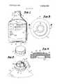
- FIG. 1is a front elevational view of the medical liquid container as it is supplied to the hospitals;
- FIG. 2is an enlarged perspective view of an upper end of the container showing its outer cap removed;
- FIG. 3is a top plan view of a puncturable resealable diaphragm portion of the injection site
- FIG. 4is a sectional view taken along line 4-4 of FIG. 3.
- FIG. 5is an enlarged sectional view showing the method of assembling the injection site
- FIG. 6is an enlarged sectional view of the injection site that has been assembled
- FIG. 7is a further enlarged sectional view of the upper portion of the injection site showing the compressed edge of the diaphragm.
- FIG. 8is a further enlarged sectional view of a lower portion of the injection site showing the means for locking the tube and retainer together.
- bottle 2is shown in FIG. 1 having a neck 4 with an external flange 6. Secured to flange 6 is an outer cap 8 which houses the injection site. The bottle 2 is supported by a series of feet such as 10 and 12 at its lower end. Between feet 10 and I2 is a recess 14 that contains a hinged hanger 16. A front of the bottle has a label 210 located between calibrations 21a and 21b.
- a sterile liquid 18 and a sterile gas 19, such as airare within the bottle. It is into this air space 19 that an additive medication can be injected immediately prior to administering the liquid 18. It is to such an injection site that this invention relates.
- FIG. 2the perspective view shows the outer cap 8 removed from the bottle to expose the inner cap and the injection site.
- This outer capis shown frangibly connected to the bottle by a series of frangible webs.
- This outer capcould be a frangible cap such as disclosed in a copending application entitled, Frangible Closure System for Medical Liquid Container and Method of Making Same," Ser. No. 338,685, invented by Pradip Choksi.
- the inner closure of FIG. 2includes a transverse wall 22 that is joined to an upstanding'collar 24 which is permanently sealed to container neck collar 26.
- an upstanding rigid thermoplastic tube 28Integrally formed with the inner closure transverse wall 22 is an upstanding rigid thermoplastic tube 28 that has an outlet structure for connecting to an administration set through which liquid is dispensed to the patient.
- a rigid upstanding tube 30integrally formed with transverse wall 22 that forms a portion of the injection site structure which is indicated generally at 20.
- a'thermoplastic metal foil 32Hermetically sealing off the outer end of both-rigid tubes 28 and 30 is a'thermoplastic metal foil 32 which is shown in FIG. 2.
- This foil 32is preferably in two portions so that the foil can be peeled back from either tube without interfering with the foils seal to the other tube.
- This foil on rigid tube 30is peeled back immediately before use to expose a puncturable resealable diaphragm 34.
- the puncturable resealable diaphragm 34shown in the enlarged top view of FIG. 3, includes a peripheral sealing portion 36 and a central puncture portion 38. Puncture portion 38 is surrounded by an upstanding target ring 40 that acts as a guide for locating the hypodermic needle or puncturing spike on the diaphragm. As shown in FIG. 4, the central puncturing area 38 is offset upwardly from peripheral sealingportion 36 and thus forms a recess 42 in a bottom side of the diaphragm. The purpose of recess 42 and its relationship to a tubular retainer and puncturing support section will be explained later.
- rigid tube 30is clearly seen as have its lower end integrally formed with transverse wall 22 of the inner closure. There are no seams, cracks, crevices, etc. between rigid tube 30 and transverse wall 22.
- An upper end of the rigid tubehas an integral inwardly extending thermoplastic flange 44. This flange also has no joints, cracks, crevices, etc. between the flange and rigid tube 20.
- the flange 44has a beveled lead-in surface 46, a downardly directing sealing surface 48, and an inner surface 50. This inner surface 50 defines an opening through which the diaphragm can be punctured.
- the diaphragm 34is fitted onto a rigid tubular retainer 52 to form a sub-assembly.
- An upper end 54 of the tubular retainer 52engages peripheral portion 36 of diaphragm 34.
- the tubular retaineralso includes a rigid puncture support collar 56 that is supported by transverse member 58.
- transverse member 58Above transverse member 58 is a recess 60 into which the squeezed peripheral portion 36 of the diaphragm is relieved when compressively sealed against under surface 48 of flange 44.
- FIG.shows how the rigid puncture support collar 56 fits within recess 42 of diaphragm 34 to align the diaphragm with opening 50 of the flange of rigid tube 30.
- the sub-assembly of diaphragm 34 and tubular retainer 52is telescopically inserted into an inner end of the rigid tube until the peripheral section 36 of the diaphragm is tightly gripped between an upper end-54 of the retainer and an under surface 48 of flange 44.
- the diaphragm 34takes on the configuration as shown in FIG. 6.
- peripheral area 36is tightly squeezed to form a hermetic seal and a portion of the squeezed diaphragm forms an annular bulge 62 that is relieved into annular recess of the re.- tainer.
- the diaphragmis sufficiently squeezed when the lower ends of the retainer and tube are in substantial alignment.
- At a lower end 64 of retainer 52is an external recess 66.
- a portion 68 of the lower end of rigid tube 20is deformed by heat and pressure to create an annular rib or flange that extends into recess 66.
- the operation of the rigid support collar 56is shown during a needle puncture.
- the rigid support collar 56supports an area of the diaphragm immediately outward of the target ring 40.
- support collar 56will prevent excessive strain and deflection of the diaphragm from being transmitted to the critical hermetic seal area 36.
- the compressive forces on area 36 of diaphragm 34are substantially all in a direction parallel to a longitudinal axis 72 through the injection site.
- the diaphragm 34 in this constructionis relieved of inwardly directed hoop forces tending to laterally compress the diaphragm 34 against cannular 70.
- FIG. 7has a more detailed view that shows the compressed area 36 of diaphragm 34 that is tightly squeezed between surface 48 and surface 54 of the flange and'retainer respectively.
- FIG. 8the enlarged sectional view at the bottom end of the injection site shows in more detail how rib 68 is deformed into the annular recess to lock tubular retainer to the tube 30.
- the method of assembling the unique injection site of this inventionincludes placing the diaphragm 34 on retainer 52 and aligning it with the rigid puncture support collar 56. Next the sub-assembly is telescopically inserted into a lower end opening of rigid tube 20 as shown in FIG. 5 and moved into tube 20 until peripheral section 36 of the diaphragm 34 is tightly compressed in a hermetic seal. Next the lower end of rigid tube 20 is deformed by heat and pressure to form a rib 68 that occupies at least a portion of groove 66 to lock retainer 52 to rigid sleeve 20. The inner closure, diaphragm 34 and retainer 52 forms a unit that is next connected to thermoplastic metal foil 32.
- the inner closureis fitted to the neck of a liquid containing bottle 2. Then the collar 24 and the inner closure 26 of the container are heat fused together. Finally the outer cap 8 is fitted over the inner closure and secured to the bottle flange by fusing a flange 9 of the closureto bottle flange 6.
- the above described inventionworks very well when the bottle, inner closure with integral tubes 28 and 30, and tubular retainer are all made of a propylene-ethylene thermoplastic.
- the puncturable resealable diaphragm 34is of natural or synthetic rubber.
- a container with a preformed opening thereina closure with a rigid transverse wall spanning the container opening, with a periphery of the closure joined to the container at a hermetic seal; said transverse wall having an opening that is substantially smaller than the container opening and spaced from said hermetic seal; a rigid tube integrally formed with the transverse wall without any seam or joint therebetween, said tube having a passage communicating with the transverse wall opening; an inwardly extending flange integrally formed with the tube without any seam or joint therebetween; and a tubular retainer within said tube and spaced from said heremetic seal; said retainer, rigid tube, and flange combining to confine the diaphragm, and said retainer and flange engaging the diaphragm to form a hermetic seal whereby all external joints between the container and closure are remote from the diaphragm.
- closure's transverse wall, outwardly extending rigid tube, and internal flangeare formed of a homogeneous mass of thermoplastic material.
- the rigid puncture support memberincludes an annular collar engaging an inner surface of the diaphragm and the diaphragm has a peripheral area extending outwardly from the annular puncture support collar, and this peripheral area is hermetically sealed between the tubes flange and the retainer.
- the retainerhas an annular recess between the rigid puncture support and an end portion of the retainer that compressingly squeezes the diaphragm against the flange, whereby the diaphragm can at least partially deform into said recess when its peripheral area is under compression.
- An injection site structure connected to a sterile medical liquid containercomprising: a rigid thermoplastic inner closure having a transverse wall hermetically sealed to an opening of the container; a rigid upstanding thermoplastic tube integrally formed with the transverse wall and extending upwardly from said transverse wall; an inwardly extending thermoplastic flange integrally formed with an upper end portion of the upstanding tube, said flange having a beveled leadin surface and an under surface; a rubber puncturable resealable diaphragm having an upwardly offset center portion and a peripheral sealing portion fitting within said tube and having an upper annular peripheral surface in abutting engagement with the under surface of said flange; a rigid thermoplastic tubular retainer fitting within said rigid upstanding tube and compressingly squeezing an annular peripheral portion of the rubber diaphragm into hermetic sealing engagement with the under surface of said flange; a rigid thermoplastic tubular retainer fitting within said rigid upstanding tube and compressingly squeezing an annular peripheral portion of
Landscapes
- Health & Medical Sciences (AREA)
- Pharmacology & Pharmacy (AREA)
- Life Sciences & Earth Sciences (AREA)
- Animal Behavior & Ethology (AREA)
- General Health & Medical Sciences (AREA)
- Public Health (AREA)
- Veterinary Medicine (AREA)
- Medical Preparation Storing Or Oral Administration Devices (AREA)
- Closures For Containers (AREA)
Abstract
Description
Claims (19)
Priority Applications (7)
| Application Number | Priority Date | Filing Date | Title |
|---|---|---|---|
| US445852AUS3900028A (en) | 1974-02-26 | 1974-02-26 | Injection site for sterile medical liquid container |
| AU77044/74AAU481400B2 (en) | 1974-02-26 | 1974-12-31 | Injection site for sterile medical liquid container |
| CA217,183ACA1017707A (en) | 1974-02-26 | 1974-12-31 | Injection site for sterile medical liquid container and method of assembling same |
| DE19752501428DE2501428A1 (en) | 1974-02-26 | 1975-01-15 | CONTAINER FOR MEDICAL LIQUIDS |
| IT47776/75AIT1026410B (en) | 1974-02-26 | 1975-01-21 | IMPROVEMENT IN CONTAINERS FOR STERILE SOLUTIONS |
| JP50021434AJPS5813418B2 (en) | 1974-02-26 | 1975-02-20 | container |
| GB739475AGB1465041A (en) | 1974-02-26 | 1975-02-21 | Closure provided with an injection site for sealing the outlet of a medical liquid container |
Applications Claiming Priority (1)
| Application Number | Priority Date | Filing Date | Title |
|---|---|---|---|
| US445852AUS3900028A (en) | 1974-02-26 | 1974-02-26 | Injection site for sterile medical liquid container |
Publications (1)
| Publication Number | Publication Date |
|---|---|
| US3900028Atrue US3900028A (en) | 1975-08-19 |
Family
ID=23770453
Family Applications (1)
| Application Number | Title | Priority Date | Filing Date |
|---|---|---|---|
| US445852AExpired - LifetimeUS3900028A (en) | 1974-02-26 | 1974-02-26 | Injection site for sterile medical liquid container |
Country Status (6)
| Country | Link |
|---|---|
| US (1) | US3900028A (en) |
| JP (1) | JPS5813418B2 (en) |
| CA (1) | CA1017707A (en) |
| DE (1) | DE2501428A1 (en) |
| GB (1) | GB1465041A (en) |
| IT (1) | IT1026410B (en) |
Cited By (48)
| Publication number | Priority date | Publication date | Assignee | Title |
|---|---|---|---|---|
| US4013064A (en)* | 1975-06-26 | 1977-03-22 | The Kendall Company | Port means for a liquid transport system |
| US4219912A (en)* | 1978-10-10 | 1980-09-02 | Baxter Travenol Laboratories, Inc. | Injection site having thermoplastically sealed injection port |
| US4294249A (en)* | 1979-10-18 | 1981-10-13 | Cutter Laboratories, Inc. | Swage-molded injection site |
| US4307766A (en)* | 1979-05-18 | 1981-12-29 | Terumo Corporation | Plastic container for medical liquid |
| US4361253A (en)* | 1980-08-04 | 1982-11-30 | Instrumentation Laboratory Inc. | Liquid transfer device |
| US4416661A (en)* | 1981-12-24 | 1983-11-22 | Cutter Laboratories, Inc. | Injection site for fluids |
| WO1985004097A1 (en)* | 1984-03-13 | 1985-09-26 | Christensen John F | An appliance for the preparation of injectable medicaments |
| US4601703A (en)* | 1984-01-27 | 1986-07-22 | Intermedicat Gmbh | Injector for an infusion or transfusion system |
| US4665959A (en)* | 1984-10-15 | 1987-05-19 | Terumo Kabushiki Kaisha | Plug assembly |
| FR2618682A1 (en)* | 1987-07-30 | 1989-02-03 | Aguettant Lab | Device for closing and connecting containers for infusion liquids |
| WO1989002399A1 (en)* | 1987-09-10 | 1989-03-23 | Joseph Parsons Nominees Pty. Ltd. | Cap |
| US4892222A (en)* | 1988-11-25 | 1990-01-09 | Baxter International Inc. | Port assembly for a container |
| US4941517A (en)* | 1988-10-20 | 1990-07-17 | Galloway Trust | Aseptic fluid transfer apparatus and methods |
| WO1991010459A1 (en)* | 1990-01-10 | 1991-07-25 | Angeion Corporation | Hemostasis valve introducer |
| US5086783A (en)* | 1990-10-31 | 1992-02-11 | Sherwood Medical Company | Blood sampling device |
| US5086813A (en)* | 1988-10-20 | 1992-02-11 | Galloway Edwin J | Aseptic fluid transfer methods |
| US5088995A (en)* | 1990-06-22 | 1992-02-18 | Baxter International Inc. | Port and closure assembly including a resealing injection site for a container |
| US5188620A (en)* | 1988-01-25 | 1993-02-23 | Baxter International Inc. | Pre-slit injection site and associated cannula |
| US5199473A (en)* | 1988-10-20 | 1993-04-06 | Galloway Trust | Aseptic fluid transfer apparatus and methods |
| US5199948A (en)* | 1991-05-02 | 1993-04-06 | Mcgaw, Inc. | Needleless valve |
| US5211638A (en)* | 1988-01-25 | 1993-05-18 | Baxter International Inc. | Pre-slit injection site |
| US5246434A (en)* | 1991-04-26 | 1993-09-21 | Nissho Corporation | Blood collecting tube |
| US5269350A (en)* | 1988-10-20 | 1993-12-14 | Galloway Company | Aseptic fluid transfer apparatus and methods |
| US5343900A (en)* | 1988-10-20 | 1994-09-06 | Galloway Company | Needle bundle driver and methods |
| EP0721897A1 (en)* | 1995-01-10 | 1996-07-17 | Pohl GmbH & Co. KG | Device for infusion bottles or the like |
| US5658260A (en)* | 1988-01-25 | 1997-08-19 | Baxter International Inc. | Bayonet lock cannula for pre-slit y-site |
| US5776125A (en)* | 1991-07-30 | 1998-07-07 | Baxter International Inc. | Needleless vial access device |
| US5797897A (en)* | 1988-01-25 | 1998-08-25 | Baxter International Inc. | Pre-slit injection site and tapered cannula |
| US6193697B1 (en) | 1987-03-17 | 2001-02-27 | Baxter International Inc. | Pre-slit injection site and tapered cannula |
| US6213996B1 (en) | 1988-01-25 | 2001-04-10 | Baxter International Inc. | Pre-slit injection site and tapered cannula |
| US6261270B1 (en)* | 1998-09-23 | 2001-07-17 | Abbott Laboratories | Sleeve stopper |
| WO2003099191A1 (en)* | 2002-05-27 | 2003-12-04 | Fresenius Kabi Deutschland Gmbh | Connector for packaging containing medical fluids and packaging for medical fluids |
| US6663599B2 (en) | 1992-05-06 | 2003-12-16 | Cook Incorporated | Hemostasis cannula |
| US20030233083A1 (en)* | 2002-06-12 | 2003-12-18 | Vincent Houwaert | Port, a container and a method for accessing a port |
| US20050192537A1 (en)* | 1992-05-06 | 2005-09-01 | Osborne Thomas A. | Hemostasis cannula |
| US20080011707A1 (en)* | 2006-04-25 | 2008-01-17 | Naigai Kasei Co., Ltd. | Medical cap and a producing method thereof |
| US20090054865A1 (en)* | 2004-10-20 | 2009-02-26 | Torsten Brandenburger | Closing cap for containers filled with medical liquids |
| US20090065465A1 (en)* | 2007-09-12 | 2009-03-12 | Weimin Qian | Reaction Bottle with Pressure Release |
| US20100030182A1 (en)* | 2006-09-29 | 2010-02-04 | Magri Paolo | Packaging system for pharmaceutical compositions and kit for intravenous administration |
| US20100206834A1 (en)* | 2007-09-12 | 2010-08-19 | Q Labtech Llc | Chemical reactor with pressure release |
| US20130102989A1 (en)* | 2011-10-25 | 2013-04-25 | Target Brands, Inc. | Dispensing insert for a medicine containment and dispensing system and associated method |
| WO2013176587A1 (en)* | 2012-05-21 | 2013-11-28 | Carmel Pharma Ab | Protective cap |
| US20150157836A1 (en)* | 2008-01-28 | 2015-06-11 | Peter Mats Forsell | Implantable drainage device |
| US9493281B2 (en) | 2009-05-04 | 2016-11-15 | Carmel Pharma Ab | Sealing barrier arrangement |
| USD840240S1 (en) | 2011-10-25 | 2019-02-12 | Cvs Pharmacy, Inc. | Bottle |
| US20190344939A1 (en)* | 2016-09-28 | 2019-11-14 | Fresenius Kabi Deutschland Gmbh | Sealing cap for a container for holding a medical liquid |
| US20210251428A1 (en)* | 2016-12-16 | 2021-08-19 | Steven Pippin | Apparatus and method for introducing a liquid into a sealed food package |
| CN114191300A (en)* | 2020-09-02 | 2022-03-18 | 单用支持有限公司 | container |
Families Citing this family (8)
| Publication number | Priority date | Publication date | Assignee | Title |
|---|---|---|---|---|
| US4153173A (en)* | 1978-03-13 | 1979-05-08 | Baxter Travenol Laboratories, Inc. | Cap closure and method of producing same |
| DE3042229C2 (en)* | 1980-11-08 | 1983-10-27 | B. Braun Melsungen Ag, 3508 Melsungen | Insertion device for inserting elongated objects into blood vessels |
| DE3310265A1 (en)* | 1983-03-22 | 1984-09-27 | Gerhard 7166 Sulzbach-Laufen Hansen | ZIPPER FOR A CONTAINER |
| JPH0321242Y2 (en)* | 1985-07-26 | 1991-05-09 | ||
| US5649637A (en)* | 1994-06-02 | 1997-07-22 | Automatic Liquid Packaging, Inc. | Torque-resistant closure for a hermetically sealed container |
| US5595314A (en)* | 1994-06-02 | 1997-01-21 | Automatic Liquid Packaging, Inc. | Torque-resistant closure for a hermetically sealed container |
| US7632250B2 (en) | 2002-05-10 | 2009-12-15 | Tyco Healthcare Group Lp | Introducer seal assembly |
| CA2852090C (en)* | 2011-10-20 | 2016-05-24 | Becton, Dickinson And Company | Mixing element for container assemblies |
Citations (5)
| Publication number | Priority date | Publication date | Assignee | Title |
|---|---|---|---|---|
| US2364126A (en)* | 1941-12-09 | 1944-12-05 | Cantor Abraham | Receptacle closure |
| US2847007A (en)* | 1954-07-19 | 1958-08-12 | Fox Dorothy Brown | Fluid handling unit and apparatus |
| US3030955A (en)* | 1956-10-08 | 1962-04-24 | Baxter Don Inc | Plastic container |
| US3368560A (en)* | 1965-10-07 | 1968-02-13 | Theodore H. Gewecke | Outlet fitting for plastic parenteral solution container |
| US3519158A (en)* | 1968-09-27 | 1970-07-07 | Dave Chapman Goldsmith & Yamas | Aseptic connector and closure |
- 1974
- 1974-02-26USUS445852Apatent/US3900028A/ennot_activeExpired - Lifetime
- 1974-12-31CACA217,183Apatent/CA1017707A/ennot_activeExpired
- 1975
- 1975-01-15DEDE19752501428patent/DE2501428A1/ennot_activeWithdrawn
- 1975-01-21ITIT47776/75Apatent/IT1026410B/enactive
- 1975-02-20JPJP50021434Apatent/JPS5813418B2/ennot_activeExpired
- 1975-02-21GBGB739475Apatent/GB1465041A/ennot_activeExpired
Patent Citations (5)
| Publication number | Priority date | Publication date | Assignee | Title |
|---|---|---|---|---|
| US2364126A (en)* | 1941-12-09 | 1944-12-05 | Cantor Abraham | Receptacle closure |
| US2847007A (en)* | 1954-07-19 | 1958-08-12 | Fox Dorothy Brown | Fluid handling unit and apparatus |
| US3030955A (en)* | 1956-10-08 | 1962-04-24 | Baxter Don Inc | Plastic container |
| US3368560A (en)* | 1965-10-07 | 1968-02-13 | Theodore H. Gewecke | Outlet fitting for plastic parenteral solution container |
| US3519158A (en)* | 1968-09-27 | 1970-07-07 | Dave Chapman Goldsmith & Yamas | Aseptic connector and closure |
Cited By (78)
| Publication number | Priority date | Publication date | Assignee | Title |
|---|---|---|---|---|
| US4013064A (en)* | 1975-06-26 | 1977-03-22 | The Kendall Company | Port means for a liquid transport system |
| US4219912A (en)* | 1978-10-10 | 1980-09-02 | Baxter Travenol Laboratories, Inc. | Injection site having thermoplastically sealed injection port |
| US4307766A (en)* | 1979-05-18 | 1981-12-29 | Terumo Corporation | Plastic container for medical liquid |
| US4294249A (en)* | 1979-10-18 | 1981-10-13 | Cutter Laboratories, Inc. | Swage-molded injection site |
| US4361253A (en)* | 1980-08-04 | 1982-11-30 | Instrumentation Laboratory Inc. | Liquid transfer device |
| US4416661A (en)* | 1981-12-24 | 1983-11-22 | Cutter Laboratories, Inc. | Injection site for fluids |
| US4601703A (en)* | 1984-01-27 | 1986-07-22 | Intermedicat Gmbh | Injector for an infusion or transfusion system |
| WO1985004097A1 (en)* | 1984-03-13 | 1985-09-26 | Christensen John F | An appliance for the preparation of injectable medicaments |
| US4665959A (en)* | 1984-10-15 | 1987-05-19 | Terumo Kabushiki Kaisha | Plug assembly |
| US6193697B1 (en) | 1987-03-17 | 2001-02-27 | Baxter International Inc. | Pre-slit injection site and tapered cannula |
| FR2618682A1 (en)* | 1987-07-30 | 1989-02-03 | Aguettant Lab | Device for closing and connecting containers for infusion liquids |
| WO1989002399A1 (en)* | 1987-09-10 | 1989-03-23 | Joseph Parsons Nominees Pty. Ltd. | Cap |
| US6569125B2 (en) | 1988-01-25 | 2003-05-27 | Baxter International Inc | Pre-slit injection site and tapered cannula |
| US6447498B1 (en) | 1988-01-25 | 2002-09-10 | Baxter International Inc. | Pre-slit injection site and tapered cannula |
| US6261266B1 (en) | 1988-01-25 | 2001-07-17 | Baxter International Inc. | Pre-slit injection site and tapered cannula |
| US6217568B1 (en) | 1988-01-25 | 2001-04-17 | Edwards Lifesciences Corporation | Preslit injection site and tapered cannula for blood sampling |
| US6213996B1 (en) | 1988-01-25 | 2001-04-10 | Baxter International Inc. | Pre-slit injection site and tapered cannula |
| US6605076B1 (en) | 1988-01-25 | 2003-08-12 | Baxter International Inc. | Pre-slit injection site and tapered cannula |
| US5188620A (en)* | 1988-01-25 | 1993-02-23 | Baxter International Inc. | Pre-slit injection site and associated cannula |
| US5658260A (en)* | 1988-01-25 | 1997-08-19 | Baxter International Inc. | Bayonet lock cannula for pre-slit y-site |
| US5871500A (en)* | 1988-01-25 | 1999-02-16 | Baxter International Inc. | Pre-slit injection site and tapered cannula |
| US5211638A (en)* | 1988-01-25 | 1993-05-18 | Baxter International Inc. | Pre-slit injection site |
| US5797897A (en)* | 1988-01-25 | 1998-08-25 | Baxter International Inc. | Pre-slit injection site and tapered cannula |
| US5199473A (en)* | 1988-10-20 | 1993-04-06 | Galloway Trust | Aseptic fluid transfer apparatus and methods |
| US5086813A (en)* | 1988-10-20 | 1992-02-11 | Galloway Edwin J | Aseptic fluid transfer methods |
| US5343900A (en)* | 1988-10-20 | 1994-09-06 | Galloway Company | Needle bundle driver and methods |
| US5269350A (en)* | 1988-10-20 | 1993-12-14 | Galloway Company | Aseptic fluid transfer apparatus and methods |
| US4941517A (en)* | 1988-10-20 | 1990-07-17 | Galloway Trust | Aseptic fluid transfer apparatus and methods |
| US4892222A (en)* | 1988-11-25 | 1990-01-09 | Baxter International Inc. | Port assembly for a container |
| WO1991010459A1 (en)* | 1990-01-10 | 1991-07-25 | Angeion Corporation | Hemostasis valve introducer |
| EP0487712A4 (en)* | 1990-06-22 | 1992-12-02 | Baxter International Inc. | Port and closure assembly including a resealing injection site for a container |
| US5088995A (en)* | 1990-06-22 | 1992-02-18 | Baxter International Inc. | Port and closure assembly including a resealing injection site for a container |
| JP3215918B2 (en) | 1990-06-22 | 2001-10-09 | バクスター、インターナショナル、インコーポレイテッド | Port and stopper assembly including resealable injection site for container |
| US5086783A (en)* | 1990-10-31 | 1992-02-11 | Sherwood Medical Company | Blood sampling device |
| US5246434A (en)* | 1991-04-26 | 1993-09-21 | Nissho Corporation | Blood collecting tube |
| US5199948A (en)* | 1991-05-02 | 1993-04-06 | Mcgaw, Inc. | Needleless valve |
| US5776125A (en)* | 1991-07-30 | 1998-07-07 | Baxter International Inc. | Needleless vial access device |
| US7445611B2 (en) | 1992-05-06 | 2008-11-04 | Cook Incorporated | Hemostasis cannula |
| US8753317B2 (en) | 1992-05-06 | 2014-06-17 | Cook Medical Technologies Llc | Hemostasis cannula |
| US6663599B2 (en) | 1992-05-06 | 2003-12-16 | Cook Incorporated | Hemostasis cannula |
| US20040153021A1 (en)* | 1992-05-06 | 2004-08-05 | Osborne Thomas A. | Hemostasis cannula |
| US20050192537A1 (en)* | 1992-05-06 | 2005-09-01 | Osborne Thomas A. | Hemostasis cannula |
| US5678713A (en)* | 1995-01-10 | 1997-10-21 | Pohl Gmbh & Co. Kg | Arrangement on infusion bottles or the like |
| EP0721897A1 (en)* | 1995-01-10 | 1996-07-17 | Pohl GmbH & Co. KG | Device for infusion bottles or the like |
| US6261270B1 (en)* | 1998-09-23 | 2001-07-17 | Abbott Laboratories | Sleeve stopper |
| US8118802B2 (en) | 2002-05-27 | 2012-02-21 | Fresenius Kabi Deutschland Gmbh | Connector for packaging containing medical fluids and packaging for medical fluids |
| CN100398084C (en)* | 2002-05-27 | 2008-07-02 | 费森尤斯卡比德国有限公司 | Connecting piece for medical liquid containing package and package for medical liquid |
| US20110022024A1 (en)* | 2002-05-27 | 2011-01-27 | Fresenius Kabi Deutschland Gmbh | Connector for packaging containing medical fluids and packaging for medical fluids |
| WO2003099191A1 (en)* | 2002-05-27 | 2003-12-04 | Fresenius Kabi Deutschland Gmbh | Connector for packaging containing medical fluids and packaging for medical fluids |
| US7828787B2 (en) | 2002-05-27 | 2010-11-09 | Fresenius Kabi Deutschland Gmbh | Connector for packaging containing medical fluids and packaging for medical fluids |
| US6994699B2 (en)* | 2002-06-12 | 2006-02-07 | Baxter International Inc. | Port, a container and a method for accessing a port |
| US20030233083A1 (en)* | 2002-06-12 | 2003-12-18 | Vincent Houwaert | Port, a container and a method for accessing a port |
| US8211081B2 (en) | 2004-10-20 | 2012-07-03 | Fresenius Kabi Deutschland Gmbh | Closing cap for containers filled with medical liquids |
| US20090054865A1 (en)* | 2004-10-20 | 2009-02-26 | Torsten Brandenburger | Closing cap for containers filled with medical liquids |
| US20080011707A1 (en)* | 2006-04-25 | 2008-01-17 | Naigai Kasei Co., Ltd. | Medical cap and a producing method thereof |
| US9731878B2 (en)* | 2006-04-25 | 2017-08-15 | Naigai Kasei Co., Ltd. | Medical cap and a producing method thereof |
| US20100030182A1 (en)* | 2006-09-29 | 2010-02-04 | Magri Paolo | Packaging system for pharmaceutical compositions and kit for intravenous administration |
| US8721616B2 (en)* | 2006-09-29 | 2014-05-13 | Infa S.A. | Packaging system for pharmaceutical compositions and kit for intravenous administration |
| US20090065465A1 (en)* | 2007-09-12 | 2009-03-12 | Weimin Qian | Reaction Bottle with Pressure Release |
| US20100206834A1 (en)* | 2007-09-12 | 2010-08-19 | Q Labtech Llc | Chemical reactor with pressure release |
| US8142736B2 (en) | 2007-09-12 | 2012-03-27 | Weimin Qian | Reaction bottle with pressure release |
| US9694165B2 (en)* | 2008-01-28 | 2017-07-04 | Peter Mats Forsell | Implantable drainage device |
| US20150157836A1 (en)* | 2008-01-28 | 2015-06-11 | Peter Mats Forsell | Implantable drainage device |
| US9493281B2 (en) | 2009-05-04 | 2016-11-15 | Carmel Pharma Ab | Sealing barrier arrangement |
| US9775777B2 (en) | 2009-05-04 | 2017-10-03 | Carmel Pharma Ab | Sealing barrier arrangement |
| US8758322B2 (en)* | 2011-10-25 | 2014-06-24 | Target Brands, Inc. | Dispensing insert for a medicine containment and dispensing system and associated method |
| US20130102989A1 (en)* | 2011-10-25 | 2013-04-25 | Target Brands, Inc. | Dispensing insert for a medicine containment and dispensing system and associated method |
| USD840240S1 (en) | 2011-10-25 | 2019-02-12 | Cvs Pharmacy, Inc. | Bottle |
| USD840239S1 (en) | 2011-10-25 | 2019-02-12 | Cvs Pharmacy, Inc. | Bottle |
| CN104470487A (en)* | 2012-05-21 | 2015-03-25 | 卡麦尔药物股份公司 | Protective cap |
| WO2013176587A1 (en)* | 2012-05-21 | 2013-11-28 | Carmel Pharma Ab | Protective cap |
| US9956138B2 (en) | 2012-05-21 | 2018-05-01 | Carmel Pharma Ab | Protective cap |
| US20190344939A1 (en)* | 2016-09-28 | 2019-11-14 | Fresenius Kabi Deutschland Gmbh | Sealing cap for a container for holding a medical liquid |
| US11034491B2 (en)* | 2016-09-28 | 2021-06-15 | Fresenius Kabi Deutschland Gmbh | Sealing cap for a container for holding a medical liquid |
| US12116188B2 (en) | 2016-09-28 | 2024-10-15 | Fresenius Kabi Deutschland Gmbh | Sealing cap for a container for holding a medical liquid |
| US20210251428A1 (en)* | 2016-12-16 | 2021-08-19 | Steven Pippin | Apparatus and method for introducing a liquid into a sealed food package |
| US11653682B2 (en)* | 2016-12-16 | 2023-05-23 | Steven Pippin | Apparatus and method for introducing a liquid into a sealed food package |
| CN114191300A (en)* | 2020-09-02 | 2022-03-18 | 单用支持有限公司 | container |
Also Published As
| Publication number | Publication date |
|---|---|
| DE2501428A1 (en) | 1975-08-28 |
| CA1017707A (en) | 1977-09-20 |
| AU7704474A (en) | 1976-07-01 |
| IT1026410B (en) | 1978-09-20 |
| JPS5813418B2 (en) | 1983-03-14 |
| JPS50149475A (en) | 1975-11-29 |
| GB1465041A (en) | 1977-02-16 |
Similar Documents
| Publication | Publication Date | Title |
|---|---|---|
| US3900028A (en) | Injection site for sterile medical liquid container | |
| US4892222A (en) | Port assembly for a container | |
| US5100394A (en) | Pre-slit injection site | |
| US5380315A (en) | Mixing apparatus | |
| US5211638A (en) | Pre-slit injection site | |
| AU743521B2 (en) | A container closure with a frangible seal and a connector for a fluid transfer device | |
| US6599273B1 (en) | Fluid transfer device and method of use | |
| US5368586A (en) | Closure for a drug-vial | |
| JP4729022B2 (en) | Sliding reconstitution for diluent containers | |
| US6874522B2 (en) | Luer-actuated solution path connector with membrane and container using the connector and a method for establishing fluid communication with the container | |
| US4219912A (en) | Injection site having thermoplastically sealed injection port | |
| AU2004224795A1 (en) | Connector for packings containing medical liquids, and corresponding packing for medical liquids | |
| CA2261428A1 (en) | Medicament container stopper with integral spike access means | |
| US6179821B1 (en) | Membrane port for a container | |
| US4227954A (en) | Method for sealing container cap parts | |
| US3938519A (en) | Medical liquid container with a toggle film leak tester and method of leak testing with same | |
| JP3070044B2 (en) | Infusion container with communication means | |
| JP2578425B2 (en) | Plastic container with rubber stopper | |
| JPH1033635A (en) | Medical needle and drug dissolution kit | |
| JP2607232Y2 (en) | Infusion container | |
| JPH08224315A (en) | Connecting device | |
| JPH03267063A (en) | Plastic blow bag for liquid medicine | |
| JPS60163902U (en) | blood sampling equipment | |
| IE903852A1 (en) | Pre-slit injection site |
Legal Events
| Date | Code | Title | Description |
|---|---|---|---|
| AS | Assignment | Owner name:KENDALL MCGAW LABORATORIES, INC., 2525 MCGAW AVENU Free format text:ASSIGNMENT OF ASSIGNORS INTEREST. EFFECTIVE NOVEMBER 26, 1985.;ASSIGNOR:AMERICAN HOSPITAL SUPPLY CORPORATION, A CORP OF IL;REEL/FRAME:004600/0460 Effective date:19851126 Owner name:KENDALL MCGAW LABORATORIES, INC., A CORP OF OH,CAL Free format text:ASSIGNMENT OF ASSIGNORS INTEREST;ASSIGNOR:AMERICAN HOSPITAL SUPPLY CORPORATION, A CORP OF IL;REEL/FRAME:004600/0460 Effective date:19851126 | |
| AS | Assignment | Owner name:WELLS FARGO BANK, N.A. Free format text:SECURITY INTEREST;ASSIGNOR:MCGAW, INC., A CORP. OF OH;REEL/FRAME:005477/0809 Effective date:19901022 | |
| AS | Assignment | Owner name:KENDALL MCGAW LABORATORIES, INC. AN OH CORPORAT Free format text:RELEASED BY SECURED PARTY;ASSIGNOR:MANUFACTURERS HANOVER TRUST COMPANY;REEL/FRAME:005709/0001 Effective date:19901015 | |
| AS | Assignment | Owner name:KENDALL MCGAW LABORATORIES, INC., AN OH CORP. Free format text:RELEASED BY SECURED PARTY;ASSIGNOR:MANUFACTURERS HANOVER TRUST COMPANY;REEL/FRAME:005515/0206 Effective date:19901015 | |
| AS | Assignment | Owner name:MCGAW, INC., MORAINE, MONTGOMERY COUNTY, A CORP. O Free format text:MERGER;ASSIGNOR:MG ACQUISITION CORP. A CORP. OF DE (MERGED TO) KENDALL MCGAW LABORATORIES, INC., A CORP. OF OHIO;REEL/FRAME:005640/0520 Effective date:19910205 | |
| STCF | Information on status: patent grant | Free format text:PATENTED FILE - (OLD CASE ADDED FOR FILE TRACKING PURPOSES) | |
| AS | Assignment | Owner name:GENERAL ELECTRIC CAPITAL CORPORATION, A NEW YORK C Free format text:ASSIGNMENT OF ASSIGNORS INTEREST.;ASSIGNOR:MCGAW, INC., A DELAWARE CORP.;REEL/FRAME:006073/0600 Effective date:19920401 | |
| AS | Assignment | Owner name:MCGAW, INC. A CORP. OF DELAWARE Free format text:SECURITY INTEREST;ASSIGNOR:WELLS FARGO BANK, N.A.;REEL/FRAME:006139/0057 Effective date:19920401 |