US3886938A - Power operated fluid infusion device - Google Patents
Power operated fluid infusion deviceDownload PDFInfo
- Publication number
- US3886938A US3886938AUS408264AUS40826473AUS3886938AUS 3886938 AUS3886938 AUS 3886938AUS 408264 AUS408264 AUS 408264AUS 40826473 AUS40826473 AUS 40826473AUS 3886938 AUS3886938 AUS 3886938A
- Authority
- US
- United States
- Prior art keywords
- piston
- rack
- housing
- longitudinal movement
- fluid
- Prior art date
- Legal status (The legal status is an assumption and is not a legal conclusion. Google has not performed a legal analysis and makes no representation as to the accuracy of the status listed.)
- Expired - Lifetime
Links
- 239000012530fluidSubstances0.000titleclaimsabstractdescription52
- 238000001802infusionMethods0.000titleclaimsabstractdescription26
- 230000007246mechanismEffects0.000claimsabstractdescription49
- 238000004804windingMethods0.000claimsdescription10
- 230000000452restraining effectEffects0.000claimsdescription4
- 239000003814drugSubstances0.000abstractdescription8
- 229940079593drugDrugs0.000abstractdescription7
- 230000008878couplingEffects0.000description11
- 238000010168coupling processMethods0.000description11
- 238000005859coupling reactionMethods0.000description11
- 238000002347injectionMethods0.000description8
- 239000007924injectionSubstances0.000description8
- 241001465754MetazoaSpecies0.000description3
- 230000000694effectsEffects0.000description3
- 241000539152EmbolaSpecies0.000description2
- 230000005611electricityEffects0.000description2
- 239000000463materialSubstances0.000description2
- 230000000737periodic effectEffects0.000description2
- 230000002685pulmonary effectEffects0.000description2
- 239000000243solutionSubstances0.000description2
- 210000003462veinAnatomy0.000description2
- HTTJABKRGRZYRN-UHFFFAOYSA-NHeparinChemical compoundOC1C(NC(=O)C)C(O)OC(COS(O)(=O)=O)C1OC1C(OS(O)(=O)=O)C(O)C(OC2C(C(OS(O)(=O)=O)C(OC3C(C(O)C(O)C(O3)C(O)=O)OS(O)(=O)=O)C(CO)O2)NS(O)(=O)=O)C(C(O)=O)O1HTTJABKRGRZYRN-UHFFFAOYSA-N0.000description1
- 230000009471actionEffects0.000description1
- XAGFODPZIPBFFR-UHFFFAOYSA-NaluminiumChemical compound[Al]XAGFODPZIPBFFR-UHFFFAOYSA-N0.000description1
- 229910052782aluminiumInorganic materials0.000description1
- 238000004873anchoringMethods0.000description1
- 210000001367arteryAnatomy0.000description1
- 230000023555blood coagulationEffects0.000description1
- 206010061592cardiac fibrillationDiseases0.000description1
- 239000003795chemical substances by applicationSubstances0.000description1
- 238000004891communicationMethods0.000description1
- 238000010276constructionMethods0.000description1
- 239000000599controlled substanceSubstances0.000description1
- 230000002950deficientEffects0.000description1
- 230000002600fibrillogenic effectEffects0.000description1
- 239000011521glassSubstances0.000description1
- 230000005484gravityEffects0.000description1
- 229960002897heparinDrugs0.000description1
- 229920000669heparinPolymers0.000description1
- 239000003562lightweight materialSubstances0.000description1
- 238000012986modificationMethods0.000description1
- 230000004048modificationEffects0.000description1
- 229920000642polymerPolymers0.000description1
- 229940071643prefilled syringeDrugs0.000description1
- 230000009467reductionEffects0.000description1
- 238000007789sealingMethods0.000description1
- 229910001220stainless steelInorganic materials0.000description1
- 239000010935stainless steelSubstances0.000description1
- 229940126585therapeutic drugDrugs0.000description1
- 230000001225therapeutic effectEffects0.000description1
Images

Classifications
- A—HUMAN NECESSITIES
- A61—MEDICAL OR VETERINARY SCIENCE; HYGIENE
- A61M—DEVICES FOR INTRODUCING MEDIA INTO, OR ONTO, THE BODY; DEVICES FOR TRANSDUCING BODY MEDIA OR FOR TAKING MEDIA FROM THE BODY; DEVICES FOR PRODUCING OR ENDING SLEEP OR STUPOR
- A61M5/00—Devices for bringing media into the body in a subcutaneous, intra-vascular or intramuscular way; Accessories therefor, e.g. filling or cleaning devices, arm-rests
- A61M5/14—Infusion devices, e.g. infusing by gravity; Blood infusion; Accessories therefor
- A61M5/142—Pressure infusion, e.g. using pumps
- A61M5/145—Pressure infusion, e.g. using pumps using pressurised reservoirs, e.g. pressurised by means of pistons
- A61M5/1452—Pressure infusion, e.g. using pumps using pressurised reservoirs, e.g. pressurised by means of pistons pressurised by means of pistons
- A61M5/1454—Pressure infusion, e.g. using pumps using pressurised reservoirs, e.g. pressurised by means of pistons pressurised by means of pistons spring-actuated, e.g. by a clockwork
- A—HUMAN NECESSITIES
- A61—MEDICAL OR VETERINARY SCIENCE; HYGIENE
- A61M—DEVICES FOR INTRODUCING MEDIA INTO, OR ONTO, THE BODY; DEVICES FOR TRANSDUCING BODY MEDIA OR FOR TAKING MEDIA FROM THE BODY; DEVICES FOR PRODUCING OR ENDING SLEEP OR STUPOR
- A61M5/00—Devices for bringing media into the body in a subcutaneous, intra-vascular or intramuscular way; Accessories therefor, e.g. filling or cleaning devices, arm-rests
- A61M5/14—Infusion devices, e.g. infusing by gravity; Blood infusion; Accessories therefor
- A61M5/142—Pressure infusion, e.g. using pumps
- A61M5/145—Pressure infusion, e.g. using pumps using pressurised reservoirs, e.g. pressurised by means of pistons
- A61M2005/14506—Pressure infusion, e.g. using pumps using pressurised reservoirs, e.g. pressurised by means of pistons mechanically driven, e.g. spring or clockwork
- A—HUMAN NECESSITIES
- A61—MEDICAL OR VETERINARY SCIENCE; HYGIENE
- A61M—DEVICES FOR INTRODUCING MEDIA INTO, OR ONTO, THE BODY; DEVICES FOR TRANSDUCING BODY MEDIA OR FOR TAKING MEDIA FROM THE BODY; DEVICES FOR PRODUCING OR ENDING SLEEP OR STUPOR
- A61M5/00—Devices for bringing media into the body in a subcutaneous, intra-vascular or intramuscular way; Accessories therefor, e.g. filling or cleaning devices, arm-rests
- A61M5/14—Infusion devices, e.g. infusing by gravity; Blood infusion; Accessories therefor
- A61M5/142—Pressure infusion, e.g. using pumps
- A61M5/145—Pressure infusion, e.g. using pumps using pressurised reservoirs, e.g. pressurised by means of pistons
- A61M5/1452—Pressure infusion, e.g. using pumps using pressurised reservoirs, e.g. pressurised by means of pistons pressurised by means of pistons
- A61M5/14566—Pressure infusion, e.g. using pumps using pressurised reservoirs, e.g. pressurised by means of pistons pressurised by means of pistons with a replaceable reservoir for receiving a piston rod of the pump
Definitions
- ABSTRACTA portable, power operated fluid infusion device for automatically, intraveneously administering a drug to a patient.
- the devicecomprises a housing which contains a mechanically operated timing mechanism, a rack in engagement with a pinion rotated by the timing mechanism, and spiral springs for longitudinally urging the rack in a forward direction.
- a syringeAttached to the forward end of the housing in axial alignment therewith and with the rack is a syringe which has an internal axially movable piston that is coupled to and longitudinally moved by the rack.
- the springsassist the slowly rotating pinion to positively move the rack, and hence the piston, in a longitudinal direction thereby permitting a controlled amount of the drug to be automatically expelled from the syringe over an extended period of time.
- the systemcomprises a bottle containing the fluid suspended above the patient, a needle inserted into a vein or artery of the patient, and tubing connecting the bottle to the needle.
- An obvious disadvantage of the bottle systemis that it unnecessarily confines an other wise ambulatory patient to a bed.
- Other disadvantages of the bottle systemare non-adaptibility for administering fluids to animals and non-capability of use with viscuous fluids.
- the present inventionprovides a highly reliable, portable fluid infusion device that automatically discharges a predetermined amount of fluid continuously over an extended time period. Furthermore, the present invention is completely portable, light weight, attachable to an ambulatory patient or animal, and can be inexpensively made so that after its use it can be permanently discarded.
- a housinga syringe mounted on the housing, the syringe comprising an elongated container having an orifice in one end thereof and a piston mounted for longitudinal movement within the container for forcing a fluid stored in the container through the orifice. and a mechanical timing mechanism mounted on the housing.
- the timing mechanismincludes a main spring, an escapement mechanism, a gearing mechanism rotated by the main spring at a rate controlled by the escapement mechanism, a rotatable main shaft extending outwardly from the gearing mechanism and rotated thereby, the main shaft having a pinion mounted on the outwardly extending end thereof, and a member for winding the main spring of the timing mechanism.
- a rackengages the pinion of the timing mechanism and is integral with a longitudinally movable member which is coupled to the piston of the syringe, thereby longitudinally moving the piston at a predetermined rate and consequently forcing fluid at a predetermined rate through the orifice.
- the rackis urged in a longitudinal direction and into engagement with the piston for the longitudinal movement of the latter by a spring, the pinion of the timing mechanism restraining the longitudinal movement of the rack to a predetermined rate which is determined by the rotational speed of the pinion.
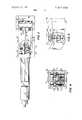
- FIG. 1is a perspective view of a presently preferred embodiment of the invention
- FIG. 2is a front elevation view of the invention wherein one side of the housing has been removed for illustrating the internal parts thereof;
- FIG. 3is a longitudinal cross sectional view of the invention taken along line 3-3 of FIG. 2;
- FIG. 4is a transverse cross sectional view taken along line 4-4 of FIG. 2, and
- FIG. 5is a perspective view with part of the housing broken away of a section of a second embodiment of the invention.
- Apparatus I0is comprised of a longitudinally extending, rectangular housing 12 and a syringe l4 removably mounted at one end of housing 12 in axial alignment therewith with means such as mounting plate 16 and screws 18.
- a strap 20is fixedly mounted on housing 12 and provides a means by which apparatus 10 can be attached to a body portion ofa patient.
- Syringe 14is comprised of an elongated cylindrical container 22 having an end 24 distal from housing 12. In distal end 24 is an orifice 26 for permitting communication between the interior of container 22 and a hypodermic needle (not shown) which can be reniovably attached at distal end 24.
- An elongated piston 28is mounted for longitudinal movement inside container 22. Piston 28 is comprised of a head section 32 integral with an elongated shaft 30 which extends into the inside of housing 12. Head section 32 is divided into a forward section 34 and a rearward section 36. Forward section 34 and rearward section 36 form an annular forward and rearward seal, respectively, with the internal wall of container 22. Consequently.
- piston 28divides the internal volume of container 22 into a forward chamber 38 for containing a fluid which is to be injected into the patient, and a rearward section 39 which is kept free from the fluid thrbugh the sealing action of forward section 34 and rearward section 36 of the piston head section 32.
- Container 22is preferably made of a transparent, nonporous material, such as glass or a plastic. It is common practice to have graduations, such as graduations 40 in FIG. 2, etched or otherwise marked on the surface of container 22 so that the amount of fluid remaining in the chamber 38, and the position of piston 28 inside container 22 can be determined. Graduations 40 can be marked off either in fluid volume or in time intervals of, for example, every two hours.
- Housing 12 of fluid infusion apparatuscan conveniently be manufactured in relatively small dimensions such as, for example, I by 1 inch square in transverse cross section by two and a half inches long.
- the housingcan have different transverse cross sectional shapes, suchas rectangular or elliptical, and can have dimensions of, for example, three-quarter by 1 inch.
- Many, easily available, strong, and light weight materialscan be used for the construction of housing 12 and include, for example, aluminum, stainless steel, and certain polymer plastic materials.
- Housing 12is comprised of a forward end 42, a rear end 44, a front panel 46, a back panel 47, and lateral sides 48 which are removably mounted on ends 42 and 44 and front and back panels 46 and 47 with means such as screws 49.
- a coupling member 50attached at a forward end to and in longitudinal axial alignment with shaft of piston 28.
- Member 50extends through a seal 52 located in forward end 42 of housing 12 and into the interior of housing 12.
- Base 54Rigidly mounted near the rearward end of coupling member 50 is a base 54 which extends transversely to and slidably engages with sides 48 of housing 12. Base 54 centers and maintains the axial alignment of coupling member 50 with piston 28 in a first, transverse plane during the longitudinal movement of these components.
- coupling member 50terminates at its rearward end in a collar 56 which has an axial bore that extends in the first transverse plane.
- a shaft 58Rigidly mounted within the bore of collar 56 and extending on either side thereof is a shaft 58.
- Two threaded guide members 60are mounted at re' spective ends of shaft 58 in a perpendicular direction thereto and are secured to shaft 58 with fastening means such as nuts 62.
- Guide members 60slidably engage front panel 46 and back panel 47 of housing 12 for maintaining axial alignment between coupling member 50 and piston 28 in a second transverse plane, which is perpendicular to the aforementioned first transverse plane, during the longitudinal movement of coupling member 50 and piston 28.
- Coupling member 50, and consequently piston 28,is urged in a forward longitudinal direction, indicated by an arrow 63, by two elongated helical springs 64 and 66.
- the forward ends of both spring 64 and spring 66engage an anchoring member such as, for example, eye bolts 68.
- Bolts 68are, in turn, fixedly mounted on forward end 42 of housing 12.
- the rearward end of springs 64 and 66are rigidly secured to base 54 with means such as couplings 70.
- Coupling member 50includes along its midportion a rack 72 integral therewith, Engaging rack 72 is a pinion 73 mounted on and integral with the end of main shaft 74 which extends outwardly from a mechanical timing mechanism 75.
- Timing mechanism 75is a conven' tional, manually wound time piece which includes a main spring 76 that conventionally operates or rotates a gearing mechanism 78 at a rate controlled by an escapement mechanism, generally shown at 80 in a manner that is well known in the art.
- Main spring 76 of timing mechanism 75is manually wound by the rotation of winding screw 82, shown in FIG. 1.
- winding screw 82is accessible from the exterior of housing 12 and is conveniently recessed in front panel 46.
- screw 82(not shown in the figure) is recessed in back panel 47.
- fluid infusion apparatus 10can be used to inject heparin, a drug which prevents blood clotting and is intraveneously administered over an extended period of time to patients who have had, for example, a pulmonary embolas. If fluid infusion apparatus 10 is of the reusable type. a prefilled syringe is mounted onto the housing 12 subsequent to the positioning of cou' pling member 50 in its most rearward position, as shown in FIG. 2. This is accomplished by rotating winding screw 82, and consequently pinion 73, which in turn, longitudinally positions rack 72 and coupling member 50.
- hypodermic needle of syringe 14is then inserted into the vein of the patient at an appropriate location, such as in the arm, and fluid infusion apparatus 10 is mounted on the arm by means of strap 20.
- Mechanical timing mechanism 75is selected such that pinion 33 will permit the full longitudinal travel of coupling member 50 in the time period desired to administer the drug.
- Fluid infusion deviceincludes a mechanical timing mechanism 91 which is similar to mechanical timing mechanism 75 shown in FIGS. 2, 3 and 4 and also described hereinabove, However, mechanical timing mechanism 91 includes a main shaft 92 which extends completely through the housing 93 of fluid infusion device 90, and a pinion 94 mounted on main shaft 92 at the middle portion thereof.
- a winding screw 96Located at one end of main shaft 92 is a winding screw 96, shown in phantom, for winding mechanical timing mechanism 90, and located at the other end of main shaft 92 is an indicator gauge 98 that is mounted on the exterior of housing 93.
- Gauge 98has a pointer 100 which is connected by reduction gears 102 to main shaft 92 and rotated thereby.
- indicia on the face of gauge 98indicates elapsed time in two hour increments at an outer ring 104 and expended solution in cubic centimeters at an inner ring 106.
- me chanical timing mechanism 91can be wound by winding screw 96 to any desired time indicated by gauge 98.
- the amount of the fluid which has been injected and the elapsed time since the injection has started, or the time remaining to complete the injectioncan be readily and easily determined by reading gauge 98.
- the fluid infusion apparatus of this inventionsupplies a constant feeding of a therapeutic fluid in a controllable amount of flow over an extended period oftime.
- Other embodiments of the inventioncan provide for an automatic, periodic, intermittent, infusion of a fluid contained within the syringe, or for a manually controllable inter mittent infusion of the fluid.
- still another embodiment of the inventioncan provide for a variable flow rate of the fluid.
- Portable, automatic fluid infusion apparatusfor administering a predetermined amount of fluid at a predetermined rate over an extended time period, the device comprising an elongate housing attachable to a user;
- a syringemounted at one end of said housing in axial alignment therewith said syringe comprising an elongated container having an orifice through one end thereof and a piston mounted for longitudinal movement within said container for forcing fluid through the said orifice;
- a mechanical power meanscoupled to and in axial alignment with said piston for longitudinally mov-- ing said piston, said power means including rack means;
- a mechanical timing mechanismmounted on said housing and coupled to said power means fo per mitting only a predetermined rate of longitudinal movement of said piston by said power means
- said mechanical timing mechanismincluding a main spring, an escapement mechanism, gearing mechanism connected to and rotated by said main spring, said escapement mechanism permitting a controlled rate of rotation of said gearing mechanism, a rotatable main shaft extending outwardly from said gearing mechanism and rotated thereby, said main shaft having a pinion mounted at the outwardly extending end thereof and in engagement with said rack means, and means for winding said main spring;
- a first centering meanstransversely rigidly mounted on said rack means for bearing against opposite sides of said housing during the longitudinal movement of said rack means for maintaining the axial alignment of said rack means and said piston in a first, transverse plane;
- a second centering meanstransversely, rigidly mounted bn said rack means perpendicular to said first centering means for bearing against at least one further side of said housing, other than said opposite sides, during the longitudinal movement of said rack means for maintaining the axial alignment of said rack means and said piston in a second, transverse plane, said second transverse plane being perpendicular to said first transverse plane;
- a helical springattached at a first end to the end of said housing at which said syringe is mounted and attached at the other end to said first centering means for longitudinally urging said rack means into engagement with said piston for the longitudinal movement thereof, said pinion of said mechani cai timing mechanism restraining the longitudinal movement of said rack means to a predetermined rate determined by the rotational speed of said pinion. and thereby permitting a predetermined amount of fluid to be forced by said piston through said orifice during a predetermined time.
- Fluid infusion apparatusas claimed in claim 1 wherein said syringe is removably mounted at one end of said housing in axial alignment therewith, and said power means is mounted within and totally enclosed by said housing in axial alignment with said piston of said
Landscapes
- Health & Medical Sciences (AREA)
- Vascular Medicine (AREA)
- Engineering & Computer Science (AREA)
- Anesthesiology (AREA)
- Biomedical Technology (AREA)
- Heart & Thoracic Surgery (AREA)
- Hematology (AREA)
- Life Sciences & Earth Sciences (AREA)
- Animal Behavior & Ethology (AREA)
- General Health & Medical Sciences (AREA)
- Public Health (AREA)
- Veterinary Medicine (AREA)
- Infusion, Injection, And Reservoir Apparatuses (AREA)
Abstract
Description
United StatesPatent 1 Szabo et a1.
3,886,938 June 3, 1975 1 1 POWER OPERATED FLUID INFUSION DEVICE [75] Inventors: Anthony W. Szabo, Livingston, N..l.;
Louis R. M. Del Guercio, Larchmont, NY.
[73] Assignee: Anthony Scala, Livingston, NJ. a
part interest [22] Filed: Oct. 23, 1973 [21] Appl. No; 408,264
[52] US. Cl 128/218 A; 128/214 F; 128/218 F [51] Int. Cl A6lm 5/20 [58] Field of Search 128/218 A, 218 F, 215, 128/234, 214 F, 218 R, DIG. l, DIG. 12, 214 R; 222/386 [56] References Cited UNITED STATES PATENTS 2,498,672 2/1950 123/218 A 2,531,267 11/1950 Harnisch 128/218 F 2,605,765 8/1952 Kollsman 128/218 F 2,671,448 3/1954 Harnisch 128/218 F 3,384,080 5/1968 Muller..................... 128/214 F 3,701,345 10/1972 Hellman et a1. 128/218 A 458,275 7/1950 Italy 128/218 A Primary Examiner-Richard A. Gaudet Assistant Examiner.l. C. McGowan Attorney, Agent, or Firm-Larson, Taylor and Hinds [57] ABSTRACT A portable, power operated fluid infusion device is disclosed for automatically, intraveneously administering a drug to a patient. The device comprises a housing which contains a mechanically operated timing mechanism, a rack in engagement with a pinion rotated by the timing mechanism, and spiral springs for longitudinally urging the rack in a forward direction. Attached to the forward end of the housing in axial alignment therewith and with the rack is a syringe which has an internal axially movable piston that is coupled to and longitudinally moved by the rack. The springs assist the slowly rotating pinion to positively move the rack, and hence the piston, in a longitudinal direction thereby permitting a controlled amount of the drug to be automatically expelled from the syringe over an extended period of time.
2 Claims, 5 Drawing Figures PATENTEDJUH 3 I975 SHEEY h Uh 1 POWER OPERATED FLUID INFUSION DEVICE BACKGROUND OF THEINVENTION 1. Field of the Invention This invention relates to portable, automatic fluid infusion devices and more particularly to a low pressure. highly reliable, completely mechanically driven infusion syringe device which permits automatically controlled drug infusion over an extended time period.
2. Description of the Prior Art In a modern hospital complex, medical personnel are increasingly being called upon to perform numerous, time consuming activities. Consequently, as constantly increasing demands are made for the time of limited number of medical personnel, it has been found that the frequency of late performance or omitted performance of the more routine activities, such as the administering of injections, has increased. Certain illnesses, such as pulmonary embolas require treatment by administering daily numerous, periodic injections of the same drug. By easing of the burden of repeatedly administering these injections by hospital personnel would provide more time for other activities. Furthermore, the omission of the delay in administering the injections can in some cases result in serious consequences. Not only is the frequent administering of the injections time consuming, it is also an additional expense for the patient.
One solution to the problem of having to frequently administer injections has been to confine the patient to a bed and to administer the medicine as a fluid with a gravity bed bottle system. The system comprises a bottle containing the fluid suspended above the patient, a needle inserted into a vein or artery of the patient, and tubing connecting the bottle to the needle. An obvious disadvantage of the bottle system is that it unnecessarily confines an other wise ambulatory patient to a bed. Other disadvantages of the bottle system are non-adaptibility for administering fluids to animals and non-capability of use with viscuous fluids.
There is prior art which attempts to remedy the aforementioned problems by utilizing syringes that are operated by electrical motors. Initially, it was believed that devices that use small electric motors to operate linkage which depresses the plunger of a standard syringe, would overcome all the aforementioned problems. However, these devices have proven unsatisfactory for a number of reasons. Most importantly, it was discovered that any introduction of electricity into the body, even on the order of microamperes and irrespective of whether the electricity is AC or DC, can cause heart fibrillations. In addition, besides being very expensive, these devices are not reliable since a loss of power, either due to a defective unit or a deenergized battery, would result in an undetectable inoperative device.
Thus, there is a need for a completely safe, nonelectrical, positiveacting, power operated syringe which is inexpensive and can be easily worn on the arm or leg of an ambulatory patient or can be strapped to the body of an animal. None of the known prior art devices have positive acting gearing mechanism for driving a memher to force a viscuous therapeutic drug fluid out of an infusion device.
SUMMARY OF THE INVENTION The present invention provides a highly reliable, portable fluid infusion device that automatically discharges a predetermined amount of fluid continuously over an extended time period. Furthermore, the present invention is completely portable, light weight, attachable to an ambulatory patient or animal, and can be inexpensively made so that after its use it can be permanently discarded.
Included in the present invention is a housing, a syringe mounted on the housing, the syringe comprising an elongated container having an orifice in one end thereof and a piston mounted for longitudinal movement within the container for forcing a fluid stored in the container through the orifice. and a mechanical timing mechanism mounted on the housing. The timing mechanism includes a main spring, an escapement mechanism, a gearing mechanism rotated by the main spring at a rate controlled by the escapement mechanism, a rotatable main shaft extending outwardly from the gearing mechanism and rotated thereby, the main shaft having a pinion mounted on the outwardly extending end thereof, and a member for winding the main spring of the timing mechanism. A rack engages the pinion of the timing mechanism and is integral with a longitudinally movable member which is coupled to the piston of the syringe, thereby longitudinally moving the piston at a predetermined rate and consequently forcing fluid at a predetermined rate through the orifice. The rack is urged in a longitudinal direction and into engagement with the piston for the longitudinal movement of the latter by a spring, the pinion of the timing mechanism restraining the longitudinal movement of the rack to a predetermined rate which is determined by the rotational speed of the pinion.
Other features and advantages of the invention will be set forth in, or apparent from, the detailed description of the presently preferred embodiments thereof found hereinbelow.
BRIEF DESCRIPTION OF THE DRAWINGS In the drawings in which like reference numerals denote like elements:
FIG. 1 is a perspective view of a presently preferred embodiment of the invention;
FIG. 2 is a front elevation view of the invention wherein one side of the housing has been removed for illustrating the internal parts thereof;
FIG. 3 is a longitudinal cross sectional view of the invention taken along line 3-3 of FIG. 2;
FIG. 4 is a transverse cross sectional view taken along line 4-4 of FIG. 2, and
FIG. 5 is a perspective view with part of the housing broken away of a section of a second embodiment of the invention.
DETAILED DESCRIPTION OF A PREFERRED EMBODIMENT With reference to FIG. 1, a presently preferred embodiment of afluid infusion apparatus 10 is shown according to the invention. Apparatus I0 is comprised of a longitudinally extending,rectangular housing 12 and a syringe l4 removably mounted at one end ofhousing 12 in axial alignment therewith with means such asmounting plate 16 andscrews 18. Astrap 20 is fixedly mounted onhousing 12 and provides a means by whichapparatus 10 can be attached to a body portion ofa patient.
Syringe 14 is comprised of an elongatedcylindrical container 22 having anend 24 distal fromhousing 12. Indistal end 24 is anorifice 26 for permitting communication between the interior ofcontainer 22 and a hypodermic needle (not shown) which can be reniovably attached atdistal end 24. Anelongated piston 28 is mounted for longitudinal movement insidecontainer 22. Piston 28 is comprised of ahead section 32 integral with anelongated shaft 30 which extends into the inside ofhousing 12.Head section 32 is divided into aforward section 34 and arearward section 36.Forward section 34 and rearwardsection 36 form an annular forward and rearward seal, respectively, with the internal wall ofcontainer 22. Consequently.piston 28 divides the internal volume ofcontainer 22 into aforward chamber 38 for containing a fluid which is to be injected into the patient, and arearward section 39 which is kept free from the fluid thrbugh the sealing action offorward section 34 and rearwardsection 36 of thepiston head section 32.Container 22 is preferably made of a transparent, nonporous material, such as glass or a plastic. It is common practice to have graduations, such asgraduations 40 in FIG. 2, etched or otherwise marked on the surface ofcontainer 22 so that the amount of fluid remaining in thechamber 38, and the position ofpiston 28 insidecontainer 22 can be determined.Graduations 40 can be marked off either in fluid volume or in time intervals of, for example, every two hours.
With reference to FIG. 2, there is shown acoupling member 50 attached at a forward end to and in longitudinal axial alignment with shaft ofpiston 28.Member 50 extends through aseal 52 located inforward end 42 ofhousing 12 and into the interior ofhousing 12. Rigidly mounted near the rearward end of couplingmember 50 is a base 54 which extends transversely to and slidably engages withsides 48 ofhousing 12.Base 54 centers and maintains the axial alignment ofcoupling member 50 withpiston 28 in a first, transverse plane during the longitudinal movement of these components. As best shown in FIGS. 3 and 4,coupling member 50 terminates at its rearward end in acollar 56 which has an axial bore that extends in the first transverse plane. Rigidly mounted within the bore ofcollar 56 and extending on either side thereof is ashaft 58. Two threadedguide members 60 are mounted at re' spective ends ofshaft 58 in a perpendicular direction thereto and are secured toshaft 58 with fastening means such as nuts 62.Guide members 60 slidably engagefront panel 46 and backpanel 47 ofhousing 12 for maintaining axial alignment betweencoupling member 50 andpiston 28 in a second transverse plane, which is perpendicular to the aforementioned first transverse plane, during the longitudinal movement ofcoupling member 50 andpiston 28.
Couplingmember 50, and consequentlypiston 28, is urged in a forward longitudinal direction, indicated by anarrow 63, by two elongatedhelical springs spring 64 andspring 66 engage an anchoring member such as, for example,eye bolts 68.Bolts 68 are, in turn, fixedly mounted onforward end 42 ofhousing 12. The rearward end ofsprings base 54 with means such ascouplings 70. Thus, assprings piston 28 is urged intocontainer 22 to force fluid out through the hypodermic needle.
Couplingmember 50 includes along its midportion arack 72 integral therewith, Engagingrack 72 is apinion 73 mounted on and integral with the end ofmain shaft 74 which extends outwardly from amechanical timing mechanism 75.Timing mechanism 75 is a conven' tional, manually wound time piece which includes a main spring 76 that conventionally operates or rotates agearing mechanism 78 at a rate controlled by an escapement mechanism, generally shown at 80 in a manner that is well known in the art. Main spring 76 oftiming mechanism 75 is manually wound by the rotation of windingscrew 82, shown in FIG. 1. As is shown in FIG. 1, windingscrew 82 is accessible from the exterior ofhousing 12 and is conveniently recessed infront panel 46. In another embodiment as shown in FIG. 2, screw 82 (not shown in the figure) is recessed inback panel 47.
In operation,fluid infusion apparatus 10 can be used to inject heparin, a drug which prevents blood clotting and is intraveneously administered over an extended period of time to patients who have had, for example, a pulmonary embolas. Iffluid infusion apparatus 10 is of the reusable type. a prefilled syringe is mounted onto thehousing 12 subsequent to the positioning of cou'pling member 50 in its most rearward position, as shown in FIG. 2. This is accomplished by rotating windingscrew 82, and consequentlypinion 73, which in turn, longitudinally positions rack 72 andcoupling member 50. The hypodermic needle ofsyringe 14 is then inserted into the vein of the patient at an appropriate location, such as in the arm, andfluid infusion apparatus 10 is mounted on the arm by means ofstrap 20.Mechanical timing mechanism 75 is selected such that pinion 33 will permit the full longitudinal travel ofcoupling member 50 in the time period desired to administer the drug.
A second embodiment of a fluid infusion device according to the invention, denoted 90, is shown in FIG. 5 and is similar tofluid infusion device 10 described hereinabove, except that it further includes an elapsed time and expended fluid indicator. Fluid infusion device includes amechanical timing mechanism 91 which is similar tomechanical timing mechanism 75 shown in FIGS. 2, 3 and 4 and also described hereinabove, However,mechanical timing mechanism 91 includes amain shaft 92 which extends completely through the housing 93 offluid infusion device 90, and apinion 94 mounted onmain shaft 92 at the middle portion thereof. Located at one end ofmain shaft 92 is a windingscrew 96, shown in phantom, for windingmechanical timing mechanism 90, and located at the other end ofmain shaft 92 is an indicator gauge 98 that is mounted on the exterior of housing 93. Gauge 98 has apointer 100 which is connected byreduction gears 102 tomain shaft 92 and rotated thereby. indicia on the face of gauge 98 indicates elapsed time in two hour increments at anouter ring 104 and expended solution in cubic centimeters at aninner ring 106. Thus, mechanical timing mechanism 91 can be wound by windingscrew 96 to any desired time indicated by gauge 98. Furthermore, the amount of the fluid which has been injected and the elapsed time since the injection has started, or the time remaining to complete the injection, can be readily and easily determined by reading gauge 98.
It is apparent from the foregoing that the fluid infusion apparatus of this invention supplies a constant feeding of a therapeutic fluid in a controllable amount of flow over an extended period oftime. Other embodiments of the invention can provide for an automatic, periodic, intermittent, infusion of a fluid contained within the syringe, or for a manually controllable inter mittent infusion of the fluid. Furthermore, still another embodiment of the invention can provide for a variable flow rate of the fluid.
Although the invention has been described in detail with respect to an exemplary embodiment thereof, it will be understood by those of ordinary skill in the art that variations and modifications may be effected within the scope and spirit of the invention.
I claim:
1. Portable, automatic fluid infusion apparatus for administering a predetermined amount of fluid at a predetermined rate over an extended time period, the device comprising an elongate housing attachable to a user;
a syringe mounted at one end of said housing in axial alignment therewith said syringe comprising an elongated container having an orifice through one end thereof and a piston mounted for longitudinal movement within said container for forcing fluid through the said orifice;
a mechanical power means coupled to and in axial alignment with said piston for longitudinally mov-- ing said piston, said power means including rack means;
a mechanical timing mechanism mounted on said housing and coupled to said power means fo per mitting only a predetermined rate of longitudinal movement of said piston by said power means,
thereby providing a predetermined flow of said fluid from said syringe, said mechanical timing mechanism including a main spring, an escapement mechanism, gearing mechanism connected to and rotated by said main spring, said escapement mechanism permitting a controlled rate of rotation of said gearing mechanism, a rotatable main shaft extending outwardly from said gearing mechanism and rotated thereby, said main shaft having a pinion mounted at the outwardly extending end thereof and in engagement with said rack means, and means for winding said main spring;
a first centering means transversely rigidly mounted on said rack means for bearing against opposite sides of said housing during the longitudinal movement of said rack means for maintaining the axial alignment of said rack means and said piston in a first, transverse plane;
a second centering means transversely, rigidly mounted bn said rack means perpendicular to said first centering means for bearing against at least one further side of said housing, other than said opposite sides, during the longitudinal movement of said rack means for maintaining the axial alignment of said rack means and said piston in a second, transverse plane, said second transverse plane being perpendicular to said first transverse plane; and
a helical spring attached at a first end to the end of said housing at which said syringe is mounted and attached at the other end to said first centering means for longitudinally urging said rack means into engagement with said piston for the longitudinal movement thereof, said pinion of said mechani cai timing mechanism restraining the longitudinal movement of said rack means to a predetermined rate determined by the rotational speed of said pinion. and thereby permitting a predetermined amount of fluid to be forced by said piston through said orifice during a predetermined time.
2. Fluid infusion apparatus as claimed inclaim 1 wherein said syringe is removably mounted at one end of said housing in axial alignment therewith, and said power means is mounted within and totally enclosed by said housing in axial alignment with said piston of said
Claims (2)
1. Portable, automatic fluid infusion apparatus for administering a predetermined amount of fluid at a predetermined rate over an extended time period, the device comprising an elongate housing attachable to a user; a syringe mounted at one end of said housing in axial alignment therewith said syringe comprising an elongated container having an orifice through one end thereof and a piston mounted for longitudinal movement within said container for forcing fluid through the said orifice; a mechanical power means coupled to and in axial alignment with said piston for longitudinally moving said piston, said power means including rack means; a mechanical timing mechanism mounted on said housing and coupled to said power means for permitting only a predetermined rate of longitudinal movement of said piston by said power means, thereby providing a predetermined flow of said fluid from said syringe, said mechanical timing mechanism including a main spring, an escapement mechanism, gearing mechanism connected to and rotated by said main spring, said escapement mechanism permitting a controlled rate of rotation of said gearing mechanism, a rotatable main shaft extending outwardly from said gearing mechanism and rotated thereby, said main shaft having a pinion mounted at the outwardly extending end thereof and in engagement with said rack means, and means for winding said main spring; a first centering means transversely rigidly mounted on said rack means for bearing against opposite sides of said housing during the longitudinal movement of said rack means for maintaining the axial alignment of said rack means and said piston in a first, transverse plane; a second centering means transversely, rigidly mounted on said rack means perpendicular to said first centering means for bearing against at least one further side of said housing, other than said opposite sides, during the longitudinal movement of said rack means for maintaining the axial alignment of said rack means and said piston in a second, transverse plane, said second transverse plane being perpendicular to said first transverse plane; and a helical spring attached at a first end to the end of said housing at which said syringe is mounted and attached at the other end to said first centering means for longitudinally urging said rack means into engagement with said piston for the longitudinal movement thereof, said pinion of said mechanical timing mechanism restraining the longitudinal movement of said rack means to a predetermined rate determined by the rotational speed of said pinion, and thereby permitting a predetermined amount of fluid to be forced by said piston through said orifice during a predetermined time.
1. Portable, automatic fluid infusion apparatus for administering a predetermined amount of fluid at a predetermined rate over an extended time period, the device comprising an elongate housing attachable to a user; a syringe mounted at one end of said housing in axial alignment therewith said syringe comprising an elongated container having an orifice through one end thereof and a piston mounted for longitudinal movement within said container for forcing fluid through the said orifice; a mechanical power means coupled to and in axial alignment with said piston for longitudinally moving said piston, said power means including rack means; a mechanical timing mechanism mounted on said housing and coupled to said power means for permitting only a predetermined rate of longitudinal movement of said piston by said power means, thereby providing a predetermined flow of said fluid from said syringe, said mechanical timing mechanism including a main spring, an escapement mechanism, gearing mechanism connected to and rotated by said main spring, said escapement mechanism permitting a controlled rate of rotation of said gearing mechanism, a rotatable main shaft extending outwardly from said gearing mechanism and rotated thereby, said main shaft having a pinion mounted at the outwardly extending end thereof and in engagement with said rack means, and means for winding said main spring; a first centering means transversely rigidly mounted on said rack means for bearing against opposite sides of said housing during the longitudinal movement of said rack means for maintaining the axial alignment of said rack means and said piston in a first, transverse plane; a second centering means transversely, rigidly mounted on said rack means perpendicular to said first centering means for bearing against at least one further side of said housing, other than said opposite sides, during the longitudinal movement of said rack means for maintaining the axial alignment of said rack means and said piston in a second, transverse plane, said second transverse plane being perpendicular to said first transverse plane; and a helical spring attached at a first end to the end of said housing at which said syringe is mounted and attached at the other end to said first centering means for longitudinally urging said rack means into engagement with said piston for the longitudinal movement thereof, said pinion of said mechanical timing mechanism restraining the longitudinal movement of said rack means to a predetermined rate determined by the rotational speed of said pinion, and thereby permitting a predetermined amount of fluid to be forced by said piston through said orifice during a predetermined time.
Priority Applications (1)
| Application Number | Priority Date | Filing Date | Title |
|---|---|---|---|
| US408264AUS3886938A (en) | 1973-10-23 | 1973-10-23 | Power operated fluid infusion device |
Applications Claiming Priority (1)
| Application Number | Priority Date | Filing Date | Title |
|---|---|---|---|
| US408264AUS3886938A (en) | 1973-10-23 | 1973-10-23 | Power operated fluid infusion device |
Publications (1)
| Publication Number | Publication Date |
|---|---|
| US3886938Atrue US3886938A (en) | 1975-06-03 |
Family
ID=23615555
Family Applications (1)
| Application Number | Title | Priority Date | Filing Date |
|---|---|---|---|
| US408264AExpired - LifetimeUS3886938A (en) | 1973-10-23 | 1973-10-23 | Power operated fluid infusion device |
Country Status (1)
| Country | Link |
|---|---|
| US (1) | US3886938A (en) |
Cited By (99)
| Publication number | Priority date | Publication date | Assignee | Title |
|---|---|---|---|---|
| US3964139A (en)* | 1975-06-16 | 1976-06-22 | Harvard Apparatus Company, Inc. | Syringe holder |
| US4044764A (en)* | 1975-10-30 | 1977-08-30 | Szabo Anthony W | Fluid infusion apparatus |
| US4059110A (en)* | 1976-10-07 | 1977-11-22 | Timex Corporation | Clockwork driven hypodermic syringe |
| FR2437216A1 (en)* | 1978-09-26 | 1980-04-25 | Arion Henri | Clockwork operated syringe for gradual medication injection - has piston pulled by cable reeling onto winder shaft of alarm clock |
| US4202333A (en)* | 1978-11-08 | 1980-05-13 | Minnesota Mining And Manufacturing Company | Fluid dispensing device |
| EP0016343A1 (en)* | 1979-02-22 | 1980-10-01 | Intermedicat GmbH | Continuous-infusion device |
| US4298000A (en)* | 1978-11-08 | 1981-11-03 | Minnesota Mining And Manufacturing Company | Fluid dispensing device |
| US4381006A (en)* | 1980-11-10 | 1983-04-26 | Abbott Laboratories | Continuous low flow rate fluid dispenser |
| US4382753A (en)* | 1979-03-09 | 1983-05-10 | Avi, Inc. | Nonpulsating IV pump and disposable pump chamber |
| US4391600A (en)* | 1979-03-09 | 1983-07-05 | Avi, Inc. | Nonpulsating IV pump and disposable pump chamber |
| US4410322A (en)* | 1979-03-09 | 1983-10-18 | Avi, Inc. | Nonpulsating TV pump and disposable pump chamber |
| US4430079A (en) | 1978-11-08 | 1984-02-07 | Minnesota Mining And Manufacturing Company | Fluid dispensing device |
| EP0092712A3 (en)* | 1982-04-28 | 1984-05-30 | Intermedicat Gmbh | Pressure infusion apparatus for medical applications |
| EP0143895A1 (en)* | 1983-09-07 | 1985-06-12 | Disetronic Ag | Portable infusion apparatus |
| FR2572288A1 (en)* | 1984-10-26 | 1986-05-02 | Infors Gmbh | INFUSION PUMP |
| US4601707A (en)* | 1980-06-03 | 1986-07-22 | Albisser Anthony M | Insulin infusion device |
| US4627835A (en)* | 1985-03-11 | 1986-12-09 | Strato Medical Corporation | Tubing assembly for infusion device |
| EP0167318A3 (en)* | 1984-06-15 | 1987-01-21 | Daltex Medical Sciences, Inc. | Fail-safe mechanical drive for syringe |
| US4648872A (en)* | 1983-11-15 | 1987-03-10 | Kamen Dean L | Volumetric pump with replaceable reservoir assembly |
| US4652260A (en)* | 1985-03-11 | 1987-03-24 | Strato Medical Corporation | Infusion device |
| US4681566A (en)* | 1984-11-30 | 1987-07-21 | Strato Medical Corporation | Infusion device |
| EP0246158A1 (en)* | 1986-05-14 | 1987-11-19 | Buffet, Jacques | External device for medical injection |
| FR2608929A1 (en)* | 1986-12-29 | 1988-07-01 | Godefroy Alain | Very-long-life time infusion apparatus |
| WO1988010129A1 (en)* | 1987-06-25 | 1988-12-29 | Nova Medical Pty. Limited | Slow delivery injection device |
| US4857048A (en)* | 1987-05-29 | 1989-08-15 | Hewlett-Packard Company | IV pump and disposable flow chamber with flow control |
| US5101679A (en)* | 1990-01-08 | 1992-04-07 | Ivac Corporation | Screw drive engagement/disengagement and decoupling mechanism |
| US5106375A (en)* | 1991-05-23 | 1992-04-21 | Ivac Corporation | Dynamic lead screw engagement and indicator |
| USD327123S (en) | 1989-12-04 | 1992-06-16 | Ivac Corporation | Syringe pump |
| US5236416A (en)* | 1991-05-23 | 1993-08-17 | Ivac Corporation | Syringe plunger position detection and alarm generation |
| US5320503A (en)* | 1988-05-17 | 1994-06-14 | Patient Solutions Inc. | Infusion device with disposable elements |
| US5545140A (en)* | 1991-05-23 | 1996-08-13 | Ivac Corporation | Syringe plunger driver |
| US5584667A (en)* | 1988-05-17 | 1996-12-17 | Davis; David L. | Method of providing uniform flow from an infusion device |
| US5803712A (en)* | 1988-05-17 | 1998-09-08 | Patient Solutions, Inc. | Method of measuring an occlusion in an infusion device with disposable elements |
| US6270479B1 (en) | 1998-10-26 | 2001-08-07 | Pharmacia Ab | Autoinjector |
| US20010041869A1 (en)* | 2000-03-23 | 2001-11-15 | Causey James D. | Control tabs for infusion devices and methods of using the same |
| US6428509B1 (en) | 1999-07-29 | 2002-08-06 | Alaris Medical Systems, Inc. | Syringe plunger driver system and method |
| US6482186B1 (en) | 1999-09-29 | 2002-11-19 | Sterling Medivations, Inc. | Reusable medication delivery device |
| US6544229B1 (en) | 2000-05-01 | 2003-04-08 | Baxter International Inc | Linearly motile infusion pump |
| US6752787B1 (en)* | 1999-06-08 | 2004-06-22 | Medtronic Minimed, Inc., | Cost-sensitive application infusion device |
| US20050157017A1 (en)* | 2004-01-21 | 2005-07-21 | Silverbrook Research Pty Ltd. | Ink refill unit having a linearly actuated plunger assembly |
| US20050160858A1 (en)* | 2002-07-24 | 2005-07-28 | M 2 Medical A/S | Shape memory alloy actuator |
| US20050192561A1 (en)* | 2002-07-24 | 2005-09-01 | M 2 Medical A/S | Infusion pump system, an infusion pump unit and an infusion pump |
| US20050251097A1 (en)* | 2002-12-23 | 2005-11-10 | M 2 Medical A/S | Flexible piston rod |
| US20060116647A1 (en)* | 2000-09-19 | 2006-06-01 | Simone Geiser | Device for administering a injectable product in doses |
| US20070179444A1 (en)* | 2005-09-26 | 2007-08-02 | M2 Medical A/S | Dispensing Fluid from an Infusion Pump System |
| US20070185449A1 (en)* | 2005-04-06 | 2007-08-09 | Morten Mernoe | Actuator with string drive #1 |
| US20070276329A1 (en)* | 2004-01-29 | 2007-11-29 | Morten Mernoe | Disposable Medicine Dispensing Device |
| US20090067989A1 (en)* | 2007-09-06 | 2009-03-12 | M2 Medical Group Holdings, Inc. | Occlusion Sensing System for Infusion Pumps |
| US20090069745A1 (en)* | 2007-09-06 | 2009-03-12 | M2 Medical Group Holdings, Inc. | Operating an Infusion Pump System |
| US7534226B2 (en) | 2005-09-26 | 2009-05-19 | M2 Group Holdings, Inc. | Dispensing fluid from an infusion pump system |
| US20090157005A1 (en)* | 2003-04-23 | 2009-06-18 | Gonnelli Robert R | Hydraulically actuated pump for long duration medicament administration |
| US20090240232A1 (en)* | 2006-03-30 | 2009-09-24 | Vakerutas,Llc | Multi-cartridge fluid delivery device |
| US20090259183A1 (en)* | 2008-04-11 | 2009-10-15 | Medtronic Minimed, Inc. | Reservoir barrier layer systems and methods |
| WO2009126596A3 (en)* | 2008-04-11 | 2009-12-10 | Medtronic Minimed, Inc. | Reservoir plunger head systems and methods |
| US20100016791A1 (en)* | 2008-04-11 | 2010-01-21 | Medtronic Minimed, Inc. | Reservoir barrier layer systems and methods |
| US7708717B2 (en) | 2005-09-26 | 2010-05-04 | M2 Group Holdings, Inc. | Operating an infusion pump system |
| US7785288B2 (en) | 2002-12-23 | 2010-08-31 | Asante Solutions, Inc. | Disposable, wearable insulin dispensing device, a combination of such a device and a programming controller and a method of controlling the operation of such a device |
| US7794426B2 (en) | 2007-05-21 | 2010-09-14 | Asante Solutions, Inc. | Infusion pump system with contamination-resistant features |
| US7833196B2 (en) | 2007-05-21 | 2010-11-16 | Asante Solutions, Inc. | Illumination instrument for an infusion pump |
| US7879026B2 (en) | 2007-09-07 | 2011-02-01 | Asante Solutions, Inc. | Controlled adjustment of medicine dispensation from an infusion pump device |
| US7887511B2 (en) | 2002-11-05 | 2011-02-15 | Asante Solutions, Inc. | Disposable wearable insulin dispensing device, a combination of such a device and a programming controller and a method of controlling the operation of such a device |
| US7892199B2 (en) | 2007-05-21 | 2011-02-22 | Asante Solutions, Inc. | Occlusion sensing for an infusion pump |
| US20110097229A1 (en)* | 2009-10-09 | 2011-04-28 | Cauley Iii Thomas Henry | Feedback Controlled Syringe Pump |
| US7935076B2 (en) | 2007-09-07 | 2011-05-03 | Asante Solutions, Inc. | Activity sensing techniques for an infusion pump system |
| US7935105B2 (en) | 2007-09-07 | 2011-05-03 | Asante Solutions, Inc. | Data storage for an infusion pump system |
| US7981102B2 (en) | 2007-05-21 | 2011-07-19 | Asante Solutions, Inc. | Removable controller for an infusion pump |
| US8079683B2 (en) | 2004-01-21 | 2011-12-20 | Silverbrook Research Pty Ltd | Inkjet printer cradle with shaped recess for receiving a printer cartridge |
| US8105279B2 (en) | 2005-09-26 | 2012-01-31 | M2 Group Holdings, Inc. | Dispensing fluid from an infusion pump system |
| US8192394B2 (en) | 2005-11-08 | 2012-06-05 | Asante Solutions, Inc. | Method and system for manual and autonomous control of an infusion pump |
| US8287514B2 (en) | 2007-09-07 | 2012-10-16 | Asante Solutions, Inc. | Power management techniques for an infusion pump system |
| US8372039B2 (en) | 2005-11-08 | 2013-02-12 | Asante Solutions, Inc. | Infusion pump system |
| US8409142B2 (en) | 2005-09-26 | 2013-04-02 | Asante Solutions, Inc. | Operating an infusion pump system |
| US8454581B2 (en) | 2011-03-16 | 2013-06-04 | Asante Solutions, Inc. | Infusion pump systems and methods |
| US8551046B2 (en) | 2006-09-18 | 2013-10-08 | Asante Solutions, Inc. | Dispensing fluid from an infusion pump system |
| USD691258S1 (en) | 2010-05-27 | 2013-10-08 | Asante Solutions, Inc. | Infusion pump |
| US8585657B2 (en) | 2011-06-21 | 2013-11-19 | Asante Solutions, Inc. | Dispensing fluid from an infusion pump system |
| CN103463695A (en)* | 2012-07-26 | 2013-12-25 | 东莞市立中新材料科技有限公司 | A micro-dosage liquid quantitative supply mechanism |
| US8852152B2 (en) | 2011-02-09 | 2014-10-07 | Asante Solutions, Inc. | Infusion pump systems and methods |
| CN104162196A (en)* | 2014-08-27 | 2014-11-26 | 苏州承乐电子科技有限公司 | Emergency needle-tube-type infusion apparatus |
| US20150057615A1 (en)* | 2005-11-08 | 2015-02-26 | Asante Solutions | Infusion Pump System |
| US20150196452A1 (en)* | 2014-01-10 | 2015-07-16 | Sebacia, Inc. | Particle containers and delivery applicators |
| US9089636B2 (en) | 2004-07-02 | 2015-07-28 | Valeritas, Inc. | Methods and devices for delivering GLP-1 and uses thereof |
| USD809134S1 (en) | 2016-03-10 | 2018-01-30 | Bigfoot Biomedical, Inc. | Infusion pump assembly |
| US20180243502A1 (en)* | 2012-08-29 | 2018-08-30 | Unl Holdings Llc | Controlled Delivery Drive Mechanisms For Drug Delivery Pumps |
| USD836769S1 (en) | 2016-12-12 | 2018-12-25 | Bigfoot Biomedical, Inc. | Insulin delivery controller |
| USD839294S1 (en) | 2017-06-16 | 2019-01-29 | Bigfoot Biomedical, Inc. | Display screen with graphical user interface for closed-loop medication delivery |
| WO2019022951A1 (en)* | 2017-07-25 | 2019-01-31 | Amgen Inc. | Drug delivery device with gear module and related method of assembly |
| US10426896B2 (en) | 2016-09-27 | 2019-10-01 | Bigfoot Biomedical, Inc. | Medicine injection and disease management systems, devices, and methods |
| US10449294B1 (en) | 2016-01-05 | 2019-10-22 | Bigfoot Biomedical, Inc. | Operating an infusion pump system |
| US20200338266A1 (en)* | 2008-10-15 | 2020-10-29 | Bigfoot Biomedical, Inc. | Infusion pump system and methods |
| US10987468B2 (en) | 2016-01-05 | 2021-04-27 | Bigfoot Biomedical, Inc. | Operating multi-modal medicine delivery systems |
| US11096624B2 (en) | 2016-12-12 | 2021-08-24 | Bigfoot Biomedical, Inc. | Alarms and alerts for medication delivery devices and systems |
| US11147914B2 (en) | 2013-07-19 | 2021-10-19 | Bigfoot Biomedical, Inc. | Infusion pump system and method |
| US11389088B2 (en) | 2017-07-13 | 2022-07-19 | Bigfoot Biomedical, Inc. | Multi-scale display of blood glucose information |
| US11464906B2 (en) | 2013-12-02 | 2022-10-11 | Bigfoot Biomedical, Inc. | Infusion pump system and method |
| US11471598B2 (en) | 2015-04-29 | 2022-10-18 | Bigfoot Biomedical, Inc. | Operating an infusion pump system |
| WO2023086247A1 (en)* | 2021-11-11 | 2023-05-19 | Carefusion 303, Inc. | Syringe with biasing member |
| US11865299B2 (en) | 2008-08-20 | 2024-01-09 | Insulet Corporation | Infusion pump systems and methods |
| US12106837B2 (en) | 2016-01-14 | 2024-10-01 | Insulet Corporation | Occlusion resolution in medication delivery devices, systems, and methods |
Citations (6)
| Publication number | Priority date | Publication date | Assignee | Title |
|---|---|---|---|---|
| US2498672A (en)* | 1947-05-26 | 1950-02-28 | Antonina S Glass | Motor drive for medical syringes |
| US2531267A (en)* | 1947-10-16 | 1950-11-21 | Harnisch Fritz | Hypodermic syringe operating device |
| US2605765A (en)* | 1947-06-05 | 1952-08-05 | Kollsman Paul | Automatic syringe |
| US2671448A (en)* | 1951-02-19 | 1954-03-09 | Georgiana W Harnisch | Automatic hypodermic syringe |
| US3384080A (en)* | 1964-10-16 | 1968-05-21 | Us Catheter & Instr Corp | Portable spring powered infusion device having escapement means controlling speed ofinfusion |
| US3701345A (en)* | 1970-09-29 | 1972-10-31 | Medrad Inc | Angiographic injector equipment |
- 1973
- 1973-10-23USUS408264Apatent/US3886938A/ennot_activeExpired - Lifetime
Patent Citations (6)
| Publication number | Priority date | Publication date | Assignee | Title |
|---|---|---|---|---|
| US2498672A (en)* | 1947-05-26 | 1950-02-28 | Antonina S Glass | Motor drive for medical syringes |
| US2605765A (en)* | 1947-06-05 | 1952-08-05 | Kollsman Paul | Automatic syringe |
| US2531267A (en)* | 1947-10-16 | 1950-11-21 | Harnisch Fritz | Hypodermic syringe operating device |
| US2671448A (en)* | 1951-02-19 | 1954-03-09 | Georgiana W Harnisch | Automatic hypodermic syringe |
| US3384080A (en)* | 1964-10-16 | 1968-05-21 | Us Catheter & Instr Corp | Portable spring powered infusion device having escapement means controlling speed ofinfusion |
| US3701345A (en)* | 1970-09-29 | 1972-10-31 | Medrad Inc | Angiographic injector equipment |
Cited By (256)
| Publication number | Priority date | Publication date | Assignee | Title |
|---|---|---|---|---|
| US3964139A (en)* | 1975-06-16 | 1976-06-22 | Harvard Apparatus Company, Inc. | Syringe holder |
| US4044764A (en)* | 1975-10-30 | 1977-08-30 | Szabo Anthony W | Fluid infusion apparatus |
| US4059110A (en)* | 1976-10-07 | 1977-11-22 | Timex Corporation | Clockwork driven hypodermic syringe |
| FR2437216A1 (en)* | 1978-09-26 | 1980-04-25 | Arion Henri | Clockwork operated syringe for gradual medication injection - has piston pulled by cable reeling onto winder shaft of alarm clock |
| US4202333A (en)* | 1978-11-08 | 1980-05-13 | Minnesota Mining And Manufacturing Company | Fluid dispensing device |
| US4298000A (en)* | 1978-11-08 | 1981-11-03 | Minnesota Mining And Manufacturing Company | Fluid dispensing device |
| US4430079A (en) | 1978-11-08 | 1984-02-07 | Minnesota Mining And Manufacturing Company | Fluid dispensing device |
| US4597754A (en)* | 1978-11-08 | 1986-07-01 | Minnesota Mining And Manufacturing Company | Long capillary tube hose assembly for fluid dispensing device |
| US4300554A (en)* | 1979-02-22 | 1981-11-17 | Intermedicat Gmbh | Portable infusion apparatus |
| EP0016343A1 (en)* | 1979-02-22 | 1980-10-01 | Intermedicat GmbH | Continuous-infusion device |
| US4382753A (en)* | 1979-03-09 | 1983-05-10 | Avi, Inc. | Nonpulsating IV pump and disposable pump chamber |
| US4391600A (en)* | 1979-03-09 | 1983-07-05 | Avi, Inc. | Nonpulsating IV pump and disposable pump chamber |
| US4410322A (en)* | 1979-03-09 | 1983-10-18 | Avi, Inc. | Nonpulsating TV pump and disposable pump chamber |
| US4601707A (en)* | 1980-06-03 | 1986-07-22 | Albisser Anthony M | Insulin infusion device |
| US4381006A (en)* | 1980-11-10 | 1983-04-26 | Abbott Laboratories | Continuous low flow rate fluid dispenser |
| EP0092712A3 (en)* | 1982-04-28 | 1984-05-30 | Intermedicat Gmbh | Pressure infusion apparatus for medical applications |
| EP0143895A1 (en)* | 1983-09-07 | 1985-06-12 | Disetronic Ag | Portable infusion apparatus |
| US4648872A (en)* | 1983-11-15 | 1987-03-10 | Kamen Dean L | Volumetric pump with replaceable reservoir assembly |
| EP0167318A3 (en)* | 1984-06-15 | 1987-01-21 | Daltex Medical Sciences, Inc. | Fail-safe mechanical drive for syringe |
| DE3439322A1 (en)* | 1984-10-26 | 1986-05-07 | Infors GmbH, 8000 München | INFUSION PUMP |
| FR2572288A1 (en)* | 1984-10-26 | 1986-05-02 | Infors Gmbh | INFUSION PUMP |
| US4681566A (en)* | 1984-11-30 | 1987-07-21 | Strato Medical Corporation | Infusion device |
| US4627835A (en)* | 1985-03-11 | 1986-12-09 | Strato Medical Corporation | Tubing assembly for infusion device |
| US4652260A (en)* | 1985-03-11 | 1987-03-24 | Strato Medical Corporation | Infusion device |
| EP0246158A1 (en)* | 1986-05-14 | 1987-11-19 | Buffet, Jacques | External device for medical injection |
| FR2608929A1 (en)* | 1986-12-29 | 1988-07-01 | Godefroy Alain | Very-long-life time infusion apparatus |
| US4857048A (en)* | 1987-05-29 | 1989-08-15 | Hewlett-Packard Company | IV pump and disposable flow chamber with flow control |
| WO1988010129A1 (en)* | 1987-06-25 | 1988-12-29 | Nova Medical Pty. Limited | Slow delivery injection device |
| US5803712A (en)* | 1988-05-17 | 1998-09-08 | Patient Solutions, Inc. | Method of measuring an occlusion in an infusion device with disposable elements |
| US6312227B1 (en) | 1988-05-17 | 2001-11-06 | I-Flow Corp. | Infusion device with disposable elements |
| US6742992B2 (en) | 1988-05-17 | 2004-06-01 | I-Flow Corporation | Infusion device with disposable elements |
| US5320503A (en)* | 1988-05-17 | 1994-06-14 | Patient Solutions Inc. | Infusion device with disposable elements |
| US20080015506A1 (en)* | 1988-05-17 | 2008-01-17 | Davis David L | Infusion device with disposable elements |
| US5584667A (en)* | 1988-05-17 | 1996-12-17 | Davis; David L. | Method of providing uniform flow from an infusion device |
| US20050013698A1 (en)* | 1988-05-17 | 2005-01-20 | Davis David Lyle | Infusion device with disposable elements |
| US6146109A (en)* | 1988-05-17 | 2000-11-14 | Alaris Medical Systems, Inc. | Infusion device with disposable elements |
| USD327123S (en) | 1989-12-04 | 1992-06-16 | Ivac Corporation | Syringe pump |
| US5101679A (en)* | 1990-01-08 | 1992-04-07 | Ivac Corporation | Screw drive engagement/disengagement and decoupling mechanism |
| US5545140A (en)* | 1991-05-23 | 1996-08-13 | Ivac Corporation | Syringe plunger driver |
| US5106375A (en)* | 1991-05-23 | 1992-04-21 | Ivac Corporation | Dynamic lead screw engagement and indicator |
| US5236416A (en)* | 1991-05-23 | 1993-08-17 | Ivac Corporation | Syringe plunger position detection and alarm generation |
| US6270479B1 (en) | 1998-10-26 | 2001-08-07 | Pharmacia Ab | Autoinjector |
| US6371939B2 (en) | 1998-10-26 | 2002-04-16 | Pharmacia Ab | Autoinjector |
| US6752787B1 (en)* | 1999-06-08 | 2004-06-22 | Medtronic Minimed, Inc., | Cost-sensitive application infusion device |
| US6428509B1 (en) | 1999-07-29 | 2002-08-06 | Alaris Medical Systems, Inc. | Syringe plunger driver system and method |
| US6482186B1 (en) | 1999-09-29 | 2002-11-19 | Sterling Medivations, Inc. | Reusable medication delivery device |
| US20100160861A1 (en)* | 2000-03-23 | 2010-06-24 | Medtronic Minimed, Inc. | Control Tabs for Infusion Devices and Methods of Using the Same |
| US20070100283A1 (en)* | 2000-03-23 | 2007-05-03 | Minimed Inc. | Control tabs for infusion devices and methods of using the same |
| US20010041869A1 (en)* | 2000-03-23 | 2001-11-15 | Causey James D. | Control tabs for infusion devices and methods of using the same |
| US8613726B2 (en) | 2000-03-23 | 2013-12-24 | Medtronic Minimed, Inc. | Control tabs for infusion devices and methods of using the same |
| US6544229B1 (en) | 2000-05-01 | 2003-04-08 | Baxter International Inc | Linearly motile infusion pump |
| US7731698B2 (en)* | 2000-09-19 | 2010-06-08 | Tecpharma Licensing Ag | Device for administering an injectable product in doses |
| US20060116647A1 (en)* | 2000-09-19 | 2006-06-01 | Simone Geiser | Device for administering a injectable product in doses |
| US20050160858A1 (en)* | 2002-07-24 | 2005-07-28 | M 2 Medical A/S | Shape memory alloy actuator |
| US20050192561A1 (en)* | 2002-07-24 | 2005-09-01 | M 2 Medical A/S | Infusion pump system, an infusion pump unit and an infusion pump |
| US7232423B2 (en) | 2002-07-24 | 2007-06-19 | M2 Medical A/S | Infusion pump system, an infusion pump unit and an infusion pump |
| US9463272B2 (en) | 2002-07-24 | 2016-10-11 | Bigfoot Biomedical, Inc. | Infusion pump system, an infusion pump unit and an infusion pump |
| US8597244B2 (en) | 2002-07-24 | 2013-12-03 | Asante Solutions, Inc. | Infusion pump system, an infusion pump unit and an infusion pump |
| US20070201992A1 (en)* | 2002-07-24 | 2007-08-30 | M2 Medical A/S | Infusion Pump System, an Infusion Pump Unit and an Infusion Pump |
| US8961462B2 (en) | 2002-07-24 | 2015-02-24 | Asante Solutions, Inc. | Infusion pump system, an infusion pump unit and an infusion pump |
| US7887511B2 (en) | 2002-11-05 | 2011-02-15 | Asante Solutions, Inc. | Disposable wearable insulin dispensing device, a combination of such a device and a programming controller and a method of controlling the operation of such a device |
| US8795233B2 (en) | 2002-11-05 | 2014-08-05 | Asante Solutions, Inc. | Disposable wearable insulin dispensing device, a combination of such a device and a programming controller and a method of controlling the operation of such a device |
| US8801655B2 (en) | 2002-11-05 | 2014-08-12 | Asante Solutions, Inc. | Wearable insulin dispensing device, and a combination of such a device and a programming controller |
| US9757512B2 (en) | 2002-11-05 | 2017-09-12 | Bigfoot Biomedical, Inc. | Wearable insulin dispensing device, and a combination of such a device and a programming controller |
| US9295777B2 (en) | 2002-11-05 | 2016-03-29 | Bigfoot Biomedical, Inc. | Disposable wearable insulin dispensing device, a combination of such a device and a programming controller and a method of controlling the operation of such a device |
| US9308319B2 (en) | 2002-11-05 | 2016-04-12 | Bigfoot Biomedical, Inc. | Wearable insulin dispensing device, and a combination of such a device and a programming controller |
| US8469920B2 (en) | 2002-12-23 | 2013-06-25 | Asante Solutions, Inc. | Wearable insulin dispensing device, and a combination of such a device and a programming controller |
| US7785288B2 (en) | 2002-12-23 | 2010-08-31 | Asante Solutions, Inc. | Disposable, wearable insulin dispensing device, a combination of such a device and a programming controller and a method of controlling the operation of such a device |
| US20070203459A1 (en)* | 2002-12-23 | 2007-08-30 | M2 Medical A/S | Flexible Piston Rod |
| US7220248B2 (en) | 2002-12-23 | 2007-05-22 | M2 Medical A/S | Flexible piston rod |
| US20050251097A1 (en)* | 2002-12-23 | 2005-11-10 | M 2 Medical A/S | Flexible piston rod |
| US11642456B2 (en) | 2003-04-23 | 2023-05-09 | Mannkind Corporation | Hydraulically actuated pump for fluid administration |
| US9125983B2 (en) | 2003-04-23 | 2015-09-08 | Valeritas, Inc. | Hydraulically actuated pump for fluid administration |
| US8070726B2 (en) | 2003-04-23 | 2011-12-06 | Valeritas, Inc. | Hydraulically actuated pump for long duration medicament administration |
| US20100217191A1 (en)* | 2003-04-23 | 2010-08-26 | Valeritas, Inc. | Hydraulically actuated pump for fluid administration |
| US10525194B2 (en) | 2003-04-23 | 2020-01-07 | Valeritas, Inc. | Hydraulically actuated pump for fluid administration |
| US20090157005A1 (en)* | 2003-04-23 | 2009-06-18 | Gonnelli Robert R | Hydraulically actuated pump for long duration medicament administration |
| US20090198185A1 (en)* | 2003-04-23 | 2009-08-06 | Gonnelli Robert R | Hydraulically actuated pump for long duration medicament administration |
| US9511187B2 (en) | 2003-04-23 | 2016-12-06 | Valeritas, Inc. | Hydraulically actuated pump for fluid administration |
| US9072828B2 (en) | 2003-04-23 | 2015-07-07 | Valeritas, Inc. | Hydraulically actuated pump for long duration medicament administration |
| US20100165059A1 (en)* | 2004-01-21 | 2010-07-01 | Silverbrook Research Pty Ltd | Dispenser unit for refilling printing unit |
| US8439497B2 (en) | 2004-01-21 | 2013-05-14 | Zamtec Ltd | Image processing apparatus with nested printer and scanner |
| US20080303882A1 (en)* | 2004-01-21 | 2008-12-11 | Silverbrook Research Pty Ltd. | Ink refill unit with incremental ink ejection accuated by print cartridge cradle |
| US7695121B2 (en)* | 2004-01-21 | 2010-04-13 | Silverbrook Research Pty Ltd | Method of refilling a printing unit |
| US7699447B2 (en)* | 2004-01-21 | 2010-04-20 | Silverbrook Research Pty Ltd | Ink refill unit with controlled incremental ink ejection for print cartridge |
| US7699448B2 (en)* | 2004-01-21 | 2010-04-20 | Silverbrook Research Pty Ltd | Ink refill unit with threaded incremental ink ejection for print cartridge |
| US7699446B2 (en)* | 2004-01-21 | 2010-04-20 | Silverbrook Research Pty Ltd | Ink refill unit with incremental millilitre ink ejection for print cartridge |
| US8007083B2 (en) | 2004-01-21 | 2011-08-30 | Silverbrook Research Pty Ltd | Refill unit for incrementally filling fluid container |
| US8042922B2 (en) | 2004-01-21 | 2011-10-25 | Silverbrook Research Pty Ltd | Dispenser unit for refilling printing unit |
| US7467861B2 (en) | 2004-01-21 | 2008-12-23 | Silverbrook Research Pty Ltd | Ink refill unit with incremental ink ejection for a print cartridge |
| US20080278553A1 (en)* | 2004-01-21 | 2008-11-13 | Silverbrook Research Pty Ltd | Ink refill unit with controlled incremental ink ejection for print cartridge |
| US20080278554A1 (en)* | 2004-01-21 | 2008-11-13 | Silverbrook Research Pty Ltd | Ink refill unit with threaded incremental ink ejection for print cartridge |
| US8047639B2 (en) | 2004-01-21 | 2011-11-01 | Silverbrook Research Pty Ltd | Refill unit for incremental millilitre fluid refill |
| US20090091607A1 (en)* | 2004-01-21 | 2009-04-09 | Silverbrook Research Pty Ltd | Method Of Refilling A Printing Unit |
| US20080246787A1 (en)* | 2004-01-21 | 2008-10-09 | Silverbrook Research Pty Ltd | Ink Refill Unit For A Print Engine Having A Compression Arrangement With Actuation Means Operable By A Controller Of The Print Engine |
| US20090096847A1 (en)* | 2004-01-21 | 2009-04-16 | Silverbrook Research Pty Ltd | Ink refill unit with incremental ink ejection mechanism |
| US7399072B2 (en)* | 2004-01-21 | 2008-07-15 | Silverbrook Research Pty Ltd | Ink refill unit having a linearly actuated plunger assembly |
| US8079683B2 (en) | 2004-01-21 | 2011-12-20 | Silverbrook Research Pty Ltd | Inkjet printer cradle with shaped recess for receiving a printer cartridge |
| US20080068427A1 (en)* | 2004-01-21 | 2008-03-20 | Silverbrook Research Pty Ltd | Ink refill unit with incremental ink ejection for a print cartridge |
| US7303268B2 (en)* | 2004-01-21 | 2007-12-04 | Silverbrook Research Pty Ltd | Ink refill unit for refilling a high speed print engine |
| US8002394B2 (en) | 2004-01-21 | 2011-08-23 | Silverbrook Research Pty Ltd | Refill unit for fluid container |
| US7802879B2 (en) | 2004-01-21 | 2010-09-28 | Silverbrook Research Pty Ltd | Ink refill unit for a print engine having a compression arrangement with actuation means operable by a controller of the print engine |
| US20050157017A1 (en)* | 2004-01-21 | 2005-07-21 | Silverbrook Research Pty Ltd. | Ink refill unit having a linearly actuated plunger assembly |
| US20050157027A1 (en)* | 2004-01-21 | 2005-07-21 | Silverbrook Research Pty Ltd | Ink refill unit for refilling a high speed print engine |
| US7857436B2 (en)* | 2004-01-21 | 2010-12-28 | Silverbrook Research Pty Ltd | Ink refill unit with incremental ink ejection mechanism |
| US20080278557A1 (en)* | 2004-01-21 | 2008-11-13 | Silverbrook Research Pty Ltd | Ink refill unit with incremental millilitre ink ejection for print cartridge |
| US7887169B2 (en) | 2004-01-21 | 2011-02-15 | Silverbrook Research Pty Ltd | Ink refill unit with incremental ink ejection accuated by print cartridge cradle |
| US20070276329A1 (en)* | 2004-01-29 | 2007-11-29 | Morten Mernoe | Disposable Medicine Dispensing Device |
| US7753879B2 (en) | 2004-01-29 | 2010-07-13 | M2 Group Holdings, Inc. | Disposable medicine dispensing device |
| US9089636B2 (en) | 2004-07-02 | 2015-07-28 | Valeritas, Inc. | Methods and devices for delivering GLP-1 and uses thereof |
| US8226608B2 (en) | 2005-04-06 | 2012-07-24 | Asante Solutions, Inc. | Medicine dispensing device |
| US20070185449A1 (en)* | 2005-04-06 | 2007-08-09 | Morten Mernoe | Actuator with string drive #1 |
| US8905995B2 (en) | 2005-04-06 | 2014-12-09 | Asante Solutions, Inc. | Medicine dispensing device |
| US10105483B2 (en) | 2005-04-06 | 2018-10-23 | Bigfoot Biomedical, Inc. | Medicine dispensing device |
| US7713238B2 (en) | 2005-04-06 | 2010-05-11 | M2 Group Holdings, Inc. | Medicine dispensing device |
| US8105279B2 (en) | 2005-09-26 | 2012-01-31 | M2 Group Holdings, Inc. | Dispensing fluid from an infusion pump system |
| US7534226B2 (en) | 2005-09-26 | 2009-05-19 | M2 Group Holdings, Inc. | Dispensing fluid from an infusion pump system |
| US7776030B2 (en) | 2005-09-26 | 2010-08-17 | Asante Solutions, Inc. | Operating an infusion pump system |
| US7981084B2 (en) | 2005-09-26 | 2011-07-19 | Asante Solutions, Inc. | Operating an infusion pump system |
| US9539388B2 (en) | 2005-09-26 | 2017-01-10 | Bigfoot Biomedical, Inc. | Operating an infusion pump system |
| US7938803B2 (en) | 2005-09-26 | 2011-05-10 | Asante Solutions, Inc. | Dispensing fluid from an infusion pump system |
| US9517301B2 (en) | 2005-09-26 | 2016-12-13 | Bigfoot Biomedical, Inc. | Operating an infusion pump system |
| US7708717B2 (en) | 2005-09-26 | 2010-05-04 | M2 Group Holdings, Inc. | Operating an infusion pump system |
| US10307536B2 (en) | 2005-09-26 | 2019-06-04 | Bigfoot Biomedical, Inc. | Operating an infusion pump system |
| US7794428B2 (en) | 2005-09-26 | 2010-09-14 | Asante Solutions, Inc. | Operating an infusion pump system |
| US8057436B2 (en) | 2005-09-26 | 2011-11-15 | Asante Solutions, Inc. | Dispensing fluid from an infusion pump system |
| US7922708B2 (en) | 2005-09-26 | 2011-04-12 | Asante Solutions, Inc. | Operating an infusion pump system |
| US8747368B2 (en) | 2005-09-26 | 2014-06-10 | Asante Solutions, Inc. | Dispensing fluid from an infusion pump system |
| US8747369B2 (en) | 2005-09-26 | 2014-06-10 | Asante Solutions, Inc. | Dispensing fluid from an infusion pump system |
| US8696633B2 (en) | 2005-09-26 | 2014-04-15 | Asante Solutions, Inc. | Operating an infusion pump system |
| US8622966B2 (en) | 2005-09-26 | 2014-01-07 | Asante Solutions, Inc. | Operating an infusion pump system |
| US10603431B2 (en) | 2005-09-26 | 2020-03-31 | Bigfoot Biomedical, Inc. | Dispensing fluid from an infusion pump system |
| US20070179444A1 (en)* | 2005-09-26 | 2007-08-02 | M2 Medical A/S | Dispensing Fluid from an Infusion Pump System |
| US7794427B2 (en) | 2005-09-26 | 2010-09-14 | Asante Solutions, Inc. | Operating an infusion pump system |
| US10064993B2 (en) | 2005-09-26 | 2018-09-04 | Bigfoot Biomedical, Inc. | Dispensing fluid from an infusion pump system |
| US7887512B2 (en) | 2005-09-26 | 2011-02-15 | Asante Solutions, Inc. | Operating an infusion pump system |
| US8282601B2 (en) | 2005-09-26 | 2012-10-09 | Asante Solutions, Inc. | Dispensing fluid from an infusion pump system |
| US9872957B2 (en) | 2005-09-26 | 2018-01-23 | Bigfoot Biomedical, Inc. | Operating an infusion pump system |
| US9314569B2 (en) | 2005-09-26 | 2016-04-19 | Bigfoot Biomedical, Inc. | Dispensing fluid from an infusion pump system |
| US8480623B2 (en) | 2005-09-26 | 2013-07-09 | Asante Solutions, Inc. | Method for dispensing fluid from an infusion pump system |
| US7789859B2 (en) | 2005-09-26 | 2010-09-07 | Asante Solutions, Inc. | Operating an infusion pump system |
| US8409142B2 (en) | 2005-09-26 | 2013-04-02 | Asante Solutions, Inc. | Operating an infusion pump system |
| US9814830B2 (en) | 2005-09-26 | 2017-11-14 | Bigfoot Biomedical, Inc. | Dispensing fluid from an infusion pump system |
| US8475408B2 (en) | 2005-11-08 | 2013-07-02 | Asante Solutions, Inc. | Infusion pump system |
| US8679060B2 (en) | 2005-11-08 | 2014-03-25 | Asante Solutions, Inc. | Infusion pump system |
| US8430847B2 (en) | 2005-11-08 | 2013-04-30 | Asante Solutions, Inc. | Infusion pump system |
| US20150057615A1 (en)* | 2005-11-08 | 2015-02-26 | Asante Solutions | Infusion Pump System |
| US8372039B2 (en) | 2005-11-08 | 2013-02-12 | Asante Solutions, Inc. | Infusion pump system |
| US9114209B2 (en) | 2005-11-08 | 2015-08-25 | Bigfoot Biomedical, Inc. | Method and system for manual and autonomous control of an infusion pump |
| US8192394B2 (en) | 2005-11-08 | 2012-06-05 | Asante Solutions, Inc. | Method and system for manual and autonomous control of an infusion pump |
| US9205192B2 (en) | 2005-11-08 | 2015-12-08 | Bigfoot Biomedical, Inc. | Method and system for manual and autonomous control of an infusion pump |
| US9687599B2 (en) | 2006-03-30 | 2017-06-27 | Valeritas, Inc. | Multi-cartridge fluid delivery device |
| US8361053B2 (en) | 2006-03-30 | 2013-01-29 | Valeritas, Inc. | Multi-cartridge fluid delivery device |
| US20090240232A1 (en)* | 2006-03-30 | 2009-09-24 | Vakerutas,Llc | Multi-cartridge fluid delivery device |
| US10493199B2 (en) | 2006-03-30 | 2019-12-03 | Valeritas, Inc. | Multi-cartridge fluid delivery device |
| US8821443B2 (en) | 2006-03-30 | 2014-09-02 | Valeritas, Inc. | Multi-cartridge fluid delivery device |
| US12246159B2 (en) | 2006-03-30 | 2025-03-11 | Mannkind Corporation | Multi-cartridge fluid delivery device |
| US20110137287A1 (en)* | 2006-03-30 | 2011-06-09 | Valeritas, Inc. | Multi-cartridge fluid delivery device |
| US7914499B2 (en) | 2006-03-30 | 2011-03-29 | Valeritas, Inc. | Multi-cartridge fluid delivery device |
| US8551046B2 (en) | 2006-09-18 | 2013-10-08 | Asante Solutions, Inc. | Dispensing fluid from an infusion pump system |
| US9480793B2 (en) | 2007-05-21 | 2016-11-01 | Bigfoot Biomedical, Inc. | Occlusion sensing for an infusion pump |
| US7794426B2 (en) | 2007-05-21 | 2010-09-14 | Asante Solutions, Inc. | Infusion pump system with contamination-resistant features |
| US9474854B2 (en) | 2007-05-21 | 2016-10-25 | Bigfoot Biomedical, Inc. | Occlusion sensing for an infusion pump |
| US8647302B2 (en) | 2007-05-21 | 2014-02-11 | Asante Solutions, Inc. | Infusion pump system with contamination-resistant features |
| US8641673B2 (en) | 2007-05-21 | 2014-02-04 | Asante Solutions, Inc. | Removable controller for an infusion pump |
| US9962482B2 (en) | 2007-05-21 | 2018-05-08 | Bigfoot Biomedical, Inc. | Removable controller for an infusion pump |
| US8152765B2 (en) | 2007-05-21 | 2012-04-10 | Asante Solutions, Inc. | Infusion pump system with contamination-resistant features |
| US8454575B2 (en) | 2007-05-21 | 2013-06-04 | Asante Solutions, Inc. | Illumination instrument for an infusion pump |
| US9440021B2 (en) | 2007-05-21 | 2016-09-13 | Bigfoot Biomedical, Inc. | Removable controller for an infusion pump |
| US8834420B2 (en) | 2007-05-21 | 2014-09-16 | Asante Solutions, Inc. | Illumination instrument for an infusion pump |
| US8852141B2 (en) | 2007-05-21 | 2014-10-07 | Asante Solutions, Inc. | Occlusion sensing for an infusion pump |
| US9717849B2 (en) | 2007-05-21 | 2017-08-01 | Bigfoot Biomedical, Inc. | Occlusion sensing for an infusion pump |
| US7892199B2 (en) | 2007-05-21 | 2011-02-22 | Asante Solutions, Inc. | Occlusion sensing for an infusion pump |
| US8211062B2 (en) | 2007-05-21 | 2012-07-03 | Asante Solutions, Inc. | Illumination instrument for an infusion pump |
| US7833196B2 (en) | 2007-05-21 | 2010-11-16 | Asante Solutions, Inc. | Illumination instrument for an infusion pump |
| US7981102B2 (en) | 2007-05-21 | 2011-07-19 | Asante Solutions, Inc. | Removable controller for an infusion pump |
| US20090069745A1 (en)* | 2007-09-06 | 2009-03-12 | M2 Medical Group Holdings, Inc. | Operating an Infusion Pump System |
| US11000645B2 (en) | 2007-09-06 | 2021-05-11 | Bigfoot Biomedical, Inc. | Operating a portable medical device |
| US12403245B2 (en) | 2007-09-06 | 2025-09-02 | Insulet Corporation | Operating a portable medical device |
| US7717903B2 (en) | 2007-09-06 | 2010-05-18 | M2 Group Holdings, Inc. | Operating an infusion pump system |
| US8109921B2 (en) | 2007-09-06 | 2012-02-07 | Asante Solutions, Inc. | Operating a portable medical device |
| US10226572B2 (en) | 2007-09-06 | 2019-03-12 | Bigfoot Biomedical, Inc. | Operating a portable medical device |
| US8870853B2 (en) | 2007-09-06 | 2014-10-28 | Asante Solutions, Inc. | Operating a portable medical device |
| US20090067989A1 (en)* | 2007-09-06 | 2009-03-12 | M2 Medical Group Holdings, Inc. | Occlusion Sensing System for Infusion Pumps |
| US7828528B2 (en) | 2007-09-06 | 2010-11-09 | Asante Solutions, Inc. | Occlusion sensing system for infusion pumps |
| US8622990B2 (en) | 2007-09-07 | 2014-01-07 | Asante Solutions, Inc. | Activity sensing techniques for an infusion pump system |
| US8685002B2 (en) | 2007-09-07 | 2014-04-01 | Asante Solutions, Inc. | Data storage for an infusion pump system |
| US10632257B2 (en) | 2007-09-07 | 2020-04-28 | Bigfoot Biomedical, Inc. | Activity sensing techniques for an infusion pump system |
| US9254362B2 (en) | 2007-09-07 | 2016-02-09 | Bigfoot Biomedical, Inc. | Activity sensing techniques for an infusion pump system |
| US10117993B2 (en) | 2007-09-07 | 2018-11-06 | Bigfoot Biomedical, Inc. | Activity sensing techniques for an infusion pump system |
| US8551070B2 (en) | 2007-09-07 | 2013-10-08 | Asante Solutions, Inc. | User profile backup system for an infusion pump device |
| US11241534B2 (en) | 2007-09-07 | 2022-02-08 | Bigfoot Biomedical, Inc. | Power management techniques for an infusion pump system |
| US7879026B2 (en) | 2007-09-07 | 2011-02-01 | Asante Solutions, Inc. | Controlled adjustment of medicine dispensation from an infusion pump device |
| US8328754B2 (en) | 2007-09-07 | 2012-12-11 | Asante Solutions, Inc. | Activity sensing techniques for an infusion pump system |
| US9381302B2 (en) | 2007-09-07 | 2016-07-05 | Bigfoot Biomedical, Inc. | User profile backup system for an infusion pump device |
| US9415158B2 (en) | 2007-09-07 | 2016-08-16 | Bigfoot Biomedical, Inc. | Power management techniques for an infusion pump system |
| US8287514B2 (en) | 2007-09-07 | 2012-10-16 | Asante Solutions, Inc. | Power management techniques for an infusion pump system |
| US8211093B2 (en) | 2007-09-07 | 2012-07-03 | Asante Solutions, Inc. | Data storage for an infusion pump system |
| US10226575B2 (en) | 2007-09-07 | 2019-03-12 | Bigfoot Biomedical, Inc. | Power management techniques for an infusion pump system |
| US7935076B2 (en) | 2007-09-07 | 2011-05-03 | Asante Solutions, Inc. | Activity sensing techniques for an infusion pump system |
| US8032226B2 (en) | 2007-09-07 | 2011-10-04 | Asante Solutions, Inc. | User profile backup system for an infusion pump device |
| US7935105B2 (en) | 2007-09-07 | 2011-05-03 | Asante Solutions, Inc. | Data storage for an infusion pump system |
| US9522232B2 (en) | 2007-09-07 | 2016-12-20 | Bigfoot Biomedical, Inc. | Data storage for an infusion pump system |
| US8894628B2 (en) | 2007-09-07 | 2014-11-25 | Asante Solutions, Inc. | Activity sensing techniques for an infusion pump system |
| US20100016791A1 (en)* | 2008-04-11 | 2010-01-21 | Medtronic Minimed, Inc. | Reservoir barrier layer systems and methods |
| US8206353B2 (en) | 2008-04-11 | 2012-06-26 | Medtronic Minimed, Inc. | Reservoir barrier layer systems and methods |
| WO2009126596A3 (en)* | 2008-04-11 | 2009-12-10 | Medtronic Minimed, Inc. | Reservoir plunger head systems and methods |
| US8702655B2 (en) | 2008-04-11 | 2014-04-22 | Medtronic Minimed, Inc. | Reservoir barrier layer systems and methods |
| US9295776B2 (en) | 2008-04-11 | 2016-03-29 | Medtronic Minimed, Inc. | Reservoir plunger head systems and methods |
| US20090326458A1 (en)* | 2008-04-11 | 2009-12-31 | Chong Colin A | Reservoir plunger head systems and methods |
| US20110192478A1 (en)* | 2008-04-11 | 2011-08-11 | Medtronic Minimed, Inc. | Reservoir barrier layer systems and methods |
| US20090259183A1 (en)* | 2008-04-11 | 2009-10-15 | Medtronic Minimed, Inc. | Reservoir barrier layer systems and methods |
| US9089637B2 (en) | 2008-04-11 | 2015-07-28 | Medtronic Minimed, Inc. | Reservoir plunger head systems and methods |
| US8858501B2 (en) | 2008-04-11 | 2014-10-14 | Medtronic Minimed, Inc. | Reservoir barrier layer systems and methods |
| US11865299B2 (en) | 2008-08-20 | 2024-01-09 | Insulet Corporation | Infusion pump systems and methods |
| US12296139B2 (en) | 2008-08-20 | 2025-05-13 | Insulet Corporation | Infusion pump systems and methods |
| US11957874B2 (en)* | 2008-10-15 | 2024-04-16 | Insulet Corporation | Infusion pump system and methods |
| US20200338266A1 (en)* | 2008-10-15 | 2020-10-29 | Bigfoot Biomedical, Inc. | Infusion pump system and methods |
| US20110097229A1 (en)* | 2009-10-09 | 2011-04-28 | Cauley Iii Thomas Henry | Feedback Controlled Syringe Pump |
| USD691258S1 (en) | 2010-05-27 | 2013-10-08 | Asante Solutions, Inc. | Infusion pump |
| US9259529B2 (en) | 2011-02-09 | 2016-02-16 | Bigfoot Biomedical, Inc. | Infusion pump systems and methods |
| US8852152B2 (en) | 2011-02-09 | 2014-10-07 | Asante Solutions, Inc. | Infusion pump systems and methods |
| US9132234B2 (en) | 2011-03-16 | 2015-09-15 | Bigfoot Biomedical, Inc. | Infusion pump systems and methods |
| US8454581B2 (en) | 2011-03-16 | 2013-06-04 | Asante Solutions, Inc. | Infusion pump systems and methods |
| US9801997B2 (en) | 2011-03-16 | 2017-10-31 | Bigfoot Biomedical, Inc. | Infusion pump systems and methods |
| US10576204B2 (en) | 2011-03-16 | 2020-03-03 | Bigfoot Biomedical, Inc. | Infusion pump systems and methods |
| US8585657B2 (en) | 2011-06-21 | 2013-11-19 | Asante Solutions, Inc. | Dispensing fluid from an infusion pump system |
| CN103463695B (en)* | 2012-07-26 | 2015-07-29 | 东莞市立中新材料科技有限公司 | A kind of micro-medicinal liquid weight feed mechanism |
| CN103463695A (en)* | 2012-07-26 | 2013-12-25 | 东莞市立中新材料科技有限公司 | A micro-dosage liquid quantitative supply mechanism |
| US20180243502A1 (en)* | 2012-08-29 | 2018-08-30 | Unl Holdings Llc | Controlled Delivery Drive Mechanisms For Drug Delivery Pumps |
| US11135356B2 (en)* | 2012-08-29 | 2021-10-05 | Unl Holdings Llc | Controlled delivery drive mechanisms for drug delivery pumps |
| US12064591B2 (en) | 2013-07-19 | 2024-08-20 | Insulet Corporation | Infusion pump system and method |
| US11147914B2 (en) | 2013-07-19 | 2021-10-19 | Bigfoot Biomedical, Inc. | Infusion pump system and method |
| US11464906B2 (en) | 2013-12-02 | 2022-10-11 | Bigfoot Biomedical, Inc. | Infusion pump system and method |
| US20150196452A1 (en)* | 2014-01-10 | 2015-07-16 | Sebacia, Inc. | Particle containers and delivery applicators |
| CN104162196A (en)* | 2014-08-27 | 2014-11-26 | 苏州承乐电子科技有限公司 | Emergency needle-tube-type infusion apparatus |
| US11471598B2 (en) | 2015-04-29 | 2022-10-18 | Bigfoot Biomedical, Inc. | Operating an infusion pump system |
| US10987468B2 (en) | 2016-01-05 | 2021-04-27 | Bigfoot Biomedical, Inc. | Operating multi-modal medicine delivery systems |
| US10449294B1 (en) | 2016-01-05 | 2019-10-22 | Bigfoot Biomedical, Inc. | Operating an infusion pump system |
| US12106837B2 (en) | 2016-01-14 | 2024-10-01 | Insulet Corporation | Occlusion resolution in medication delivery devices, systems, and methods |
| USD809134S1 (en) | 2016-03-10 | 2018-01-30 | Bigfoot Biomedical, Inc. | Infusion pump assembly |
| US11957888B2 (en) | 2016-09-27 | 2024-04-16 | Bigfoot Biomedical, Inc. | Personalizing preset meal sizes in insulin delivery system |
| US12350479B2 (en) | 2016-09-27 | 2025-07-08 | Bigfoot Biomedical, Inc. | Medicine injection and disease management systems, devices, and methods |
| US11229751B2 (en) | 2016-09-27 | 2022-01-25 | Bigfoot Biomedical, Inc. | Personalizing preset meal sizes in insulin delivery system |
| US11806514B2 (en) | 2016-09-27 | 2023-11-07 | Bigfoot Biomedical, Inc. | Medicine injection and disease management systems, devices, and methods |
| US10426896B2 (en) | 2016-09-27 | 2019-10-01 | Bigfoot Biomedical, Inc. | Medicine injection and disease management systems, devices, and methods |
| US12076160B2 (en) | 2016-12-12 | 2024-09-03 | Insulet Corporation | Alarms and alerts for medication delivery devices and systems |
| USD836769S1 (en) | 2016-12-12 | 2018-12-25 | Bigfoot Biomedical, Inc. | Insulin delivery controller |
| US11096624B2 (en) | 2016-12-12 | 2021-08-24 | Bigfoot Biomedical, Inc. | Alarms and alerts for medication delivery devices and systems |
| USD852837S1 (en) | 2017-06-16 | 2019-07-02 | Bigfoot Biomedical, Inc. | Display screen with graphical user interface for closed-loop medication delivery |
| USD839294S1 (en) | 2017-06-16 | 2019-01-29 | Bigfoot Biomedical, Inc. | Display screen with graphical user interface for closed-loop medication delivery |
| US11389088B2 (en) | 2017-07-13 | 2022-07-19 | Bigfoot Biomedical, Inc. | Multi-scale display of blood glucose information |
| WO2019022951A1 (en)* | 2017-07-25 | 2019-01-31 | Amgen Inc. | Drug delivery device with gear module and related method of assembly |
| US11617837B2 (en) | 2017-07-25 | 2023-04-04 | Amgen Inc. | Drug delivery device with gear module and related method of assembly |
| US12370317B2 (en) | 2017-07-25 | 2025-07-29 | Amgen Inc. | Drug delivery device with gear module and related method of assembly |
| WO2023086247A1 (en)* | 2021-11-11 | 2023-05-19 | Carefusion 303, Inc. | Syringe with biasing member |
Similar Documents
| Publication | Publication Date | Title |
|---|---|---|
| US3886938A (en) | Power operated fluid infusion device | |
| CA1236740A (en) | Battery operated miniature syringe infusion pump | |
| US4378014A (en) | Apparatus for and method of administering intravenous fluid | |
| US4648872A (en) | Volumetric pump with replaceable reservoir assembly | |
| US20050051580A1 (en) | Drive system for an infusion pump | |
| CA1169324A (en) | Insulin infusion device | |
| US4525164A (en) | Wearable medication infusion system with arcuated reservoir | |
| US4252118A (en) | Non-reusable drug prefilled syringe assembly and method of use | |
| US4078562A (en) | Infusion pump with feedback control | |
| US4749109A (en) | Volumetric pump with replaceable reservoir assembly | |
| CN201044845Y (en) | Automatic syringe | |
| EP0398394A2 (en) | Reservoir assembly for removable engagement with a motor drive | |
| DE69331517D1 (en) | FRICTION-FREE INFUSION PUMP | |
| JPH0411228B2 (en) | ||
| ES2123516T3 (en) | SET OF SAFETY SYRINGES FOR PRE-FILLED MEDICINE CARTRIDGES. | |
| RU2673983C1 (en) | Syringe dispenser of medicines | |
| CN215653120U (en) | A regulated liquid medicine continuous quantitative syringe | |
| CN214550531U (en) | Dual-lumen injection device | |
| CN222368141U (en) | Dosage-controllable anesthetic syringe | |
| CN112295063A (en) | Unmanned intravenous injection device | |
| CN110101936B (en) | Accurate device of dosing of oncology | |
| CN223170094U (en) | Infusion alarm device | |
| CN216535453U (en) | Auxiliary drug delivery device for intrathecal injection treatment of neurology department | |
| Poznanski | A simple device for administering barium to infants | |
| Chambers et al. | A new generation of pulsatile infusion devices |
Legal Events
| Date | Code | Title | Description |
|---|---|---|---|
| AS | Assignment | Owner name:DALTEX INDUSTRIES, INC., P.O. BOX 262, LIVINGSTON, Free format text:LICENSE;ASSIGNORS:SZABO, ANTHONY W.;DEL GUERCIO, LOUIS, R.M. (M.D.);REEL/FRAME:004055/0638 Effective date:19820901 |