US3871381A - Cold compress device - Google Patents
Cold compress deviceDownload PDFInfo
- Publication number
- US3871381A US3871381AUS358899AUS35889973AUS3871381AUS 3871381 AUS3871381 AUS 3871381AUS 358899 AUS358899 AUS 358899AUS 35889973 AUS35889973 AUS 35889973AUS 3871381 AUS3871381 AUS 3871381A
- Authority
- US
- United States
- Prior art keywords
- compress
- recited
- refrigerant
- inflatable
- wall
- Prior art date
- Legal status (The legal status is an assumption and is not a legal conclusion. Google has not performed a legal analysis and makes no representation as to the accuracy of the status listed.)
- Expired - Lifetime
Links
- 239000003507refrigerantSubstances0.000claimsabstractdescription107
- 241000124008MammaliaSpecies0.000claimsabstractdescription13
- 230000001276controlling effectEffects0.000claimsabstractdescription7
- 230000001105regulatory effectEffects0.000claimsabstractdescription6
- 238000001816coolingMethods0.000claimsdescription22
- 239000000463materialSubstances0.000claimsdescription12
- 239000012530fluidSubstances0.000claimsdescription9
- 150000008282halocarbonsChemical class0.000claimsdescription9
- CURLTUGMZLYLDI-UHFFFAOYSA-NCarbon dioxideChemical compoundO=C=OCURLTUGMZLYLDI-UHFFFAOYSA-N0.000claimsdescription6
- 239000012815thermoplastic materialSubstances0.000claimsdescription6
- 210000001520combAnatomy0.000claimsdescription5
- DDMOUSALMHHKOS-UHFFFAOYSA-N1,2-dichloro-1,1,2,2-tetrafluoroethaneChemical groupFC(F)(Cl)C(F)(F)ClDDMOUSALMHHKOS-UHFFFAOYSA-N0.000claimsdescription3
- VOPWNXZWBYDODV-UHFFFAOYSA-NChlorodifluoromethaneChemical groupFC(F)ClVOPWNXZWBYDODV-UHFFFAOYSA-N0.000claimsdescription3
- 239000004338DichlorodifluoromethaneSubstances0.000claimsdescription3
- 229910002092carbon dioxideInorganic materials0.000claimsdescription3
- 239000001569carbon dioxideSubstances0.000claimsdescription3
- PXBRQCKWGAHEHS-UHFFFAOYSA-NdichlorodifluoromethaneChemical groupFC(F)(Cl)ClPXBRQCKWGAHEHS-UHFFFAOYSA-N0.000claimsdescription3
- 235000019404dichlorodifluoromethaneNutrition0.000claimsdescription3
- 229940087091dichlorotetrafluoroethaneDrugs0.000claimsdescription3
- 230000006378damageEffects0.000abstractdescription9
- 230000000694effectsEffects0.000description14
- 208000027418Wounds and injuryDiseases0.000description8
- 208000014674injuryDiseases0.000description8
- 241000283086EquidaeSpecies0.000description6
- 239000000126substanceSubstances0.000description6
- 238000010276constructionMethods0.000description5
- 238000004891communicationMethods0.000description4
- 210000002683footAnatomy0.000description4
- 230000002459sustained effectEffects0.000description4
- 241000777300CongiopodidaeSpecies0.000description3
- 239000012141concentrateSubstances0.000description3
- 239000007788liquidSubstances0.000description3
- 238000000034methodMethods0.000description3
- 238000005057refrigerationMethods0.000description3
- 210000000707wristAnatomy0.000description3
- 208000034656ContusionsDiseases0.000description2
- 208000018982Leg injuryDiseases0.000description2
- 206010050031Muscle strainDiseases0.000description2
- ATUOYWHBWRKTHZ-UHFFFAOYSA-NPropaneChemical compoundCCCATUOYWHBWRKTHZ-UHFFFAOYSA-N0.000description2
- RAHZWNYVWXNFOC-UHFFFAOYSA-NSulphur dioxideChemical compoundO=S=ORAHZWNYVWXNFOC-UHFFFAOYSA-N0.000description2
- 210000003423ankleAnatomy0.000description2
- 239000004744fabricSubstances0.000description2
- 210000000245forearmAnatomy0.000description2
- 238000012986modificationMethods0.000description2
- 230000004048modificationEffects0.000description2
- 210000001364upper extremityAnatomy0.000description2
- 239000004215Carbon black (E152)Substances0.000description1
- 241000282412HomoSpecies0.000description1
- 241001465754MetazoaSpecies0.000description1
- 208000036366Sensation of pressureDiseases0.000description1
- 208000010040Sprains and StrainsDiseases0.000description1
- 210000001124body fluidAnatomy0.000description1
- 239000010839body fluidSubstances0.000description1
- 230000036760body temperatureEffects0.000description1
- 238000006243chemical reactionMethods0.000description1
- 239000003795chemical substances by applicationSubstances0.000description1
- 150000001875compoundsChemical class0.000description1
- 238000007796conventional methodMethods0.000description1
- 238000012937correctionMethods0.000description1
- 230000003247decreasing effectEffects0.000description1
- 230000001419dependent effectEffects0.000description1
- 229930195733hydrocarbonNatural products0.000description1
- 150000002430hydrocarbonsChemical class0.000description1
- 231100000252nontoxicToxicity0.000description1
- 230000003000nontoxic effectEffects0.000description1
- 238000012856packingMethods0.000description1
- 239000004033plasticSubstances0.000description1
- 229920003023plasticPolymers0.000description1
- 239000001294propaneSubstances0.000description1
- 210000001519tissueAnatomy0.000description1
- 231100000331toxicToxicity0.000description1
- 230000002588toxic effectEffects0.000description1
- 238000012549trainingMethods0.000description1
- 229920002554vinyl polymerPolymers0.000description1
- XLYOFNOQVPJJNP-UHFFFAOYSA-NwaterSubstancesOXLYOFNOQVPJJNP-UHFFFAOYSA-N0.000description1
Images


Classifications
- A—HUMAN NECESSITIES
- A61—MEDICAL OR VETERINARY SCIENCE; HYGIENE
- A61F—FILTERS IMPLANTABLE INTO BLOOD VESSELS; PROSTHESES; DEVICES PROVIDING PATENCY TO, OR PREVENTING COLLAPSING OF, TUBULAR STRUCTURES OF THE BODY, e.g. STENTS; ORTHOPAEDIC, NURSING OR CONTRACEPTIVE DEVICES; FOMENTATION; TREATMENT OR PROTECTION OF EYES OR EARS; BANDAGES, DRESSINGS OR ABSORBENT PADS; FIRST-AID KITS
- A61F7/00—Heating or cooling appliances for medical or therapeutic treatment of the human body
- A61F7/10—Cooling bags, e.g. ice-bags
- A—HUMAN NECESSITIES
- A61—MEDICAL OR VETERINARY SCIENCE; HYGIENE
- A61D—VETERINARY INSTRUMENTS, IMPLEMENTS, TOOLS, OR METHODS
- A61D9/00—Bandages, poultices, compresses specially adapted to veterinary purposes
- A—HUMAN NECESSITIES
- A61—MEDICAL OR VETERINARY SCIENCE; HYGIENE
- A61F—FILTERS IMPLANTABLE INTO BLOOD VESSELS; PROSTHESES; DEVICES PROVIDING PATENCY TO, OR PREVENTING COLLAPSING OF, TUBULAR STRUCTURES OF THE BODY, e.g. STENTS; ORTHOPAEDIC, NURSING OR CONTRACEPTIVE DEVICES; FOMENTATION; TREATMENT OR PROTECTION OF EYES OR EARS; BANDAGES, DRESSINGS OR ABSORBENT PADS; FIRST-AID KITS
- A61F7/00—Heating or cooling appliances for medical or therapeutic treatment of the human body
- A61F2007/0001—Body part
- A—HUMAN NECESSITIES
- A61—MEDICAL OR VETERINARY SCIENCE; HYGIENE
- A61F—FILTERS IMPLANTABLE INTO BLOOD VESSELS; PROSTHESES; DEVICES PROVIDING PATENCY TO, OR PREVENTING COLLAPSING OF, TUBULAR STRUCTURES OF THE BODY, e.g. STENTS; ORTHOPAEDIC, NURSING OR CONTRACEPTIVE DEVICES; FOMENTATION; TREATMENT OR PROTECTION OF EYES OR EARS; BANDAGES, DRESSINGS OR ABSORBENT PADS; FIRST-AID KITS
- A61F7/00—Heating or cooling appliances for medical or therapeutic treatment of the human body
- A61F2007/0054—Heating or cooling appliances for medical or therapeutic treatment of the human body with a closed fluid circuit, e.g. hot water
- A61F2007/0056—Heating or cooling appliances for medical or therapeutic treatment of the human body with a closed fluid circuit, e.g. hot water for cooling
- A—HUMAN NECESSITIES
- A61—MEDICAL OR VETERINARY SCIENCE; HYGIENE
- A61F—FILTERS IMPLANTABLE INTO BLOOD VESSELS; PROSTHESES; DEVICES PROVIDING PATENCY TO, OR PREVENTING COLLAPSING OF, TUBULAR STRUCTURES OF THE BODY, e.g. STENTS; ORTHOPAEDIC, NURSING OR CONTRACEPTIVE DEVICES; FOMENTATION; TREATMENT OR PROTECTION OF EYES OR EARS; BANDAGES, DRESSINGS OR ABSORBENT PADS; FIRST-AID KITS
- A61F7/00—Heating or cooling appliances for medical or therapeutic treatment of the human body
- A61F2007/0091—Heating or cooling appliances for medical or therapeutic treatment of the human body inflatable
Definitions
- ABSTRACTA cold compress device for treating injuries in mammals, including a flexible inflatable compress adapted to be placed adjacent an area to be treated and a source of compressed refrigerant connected to the compress.
- a channelis formed in a portion of the compress wall which must be traversed by incoming refrigerant before it enters the interior of the inflatable compress.
- the devicealso includes means interposed between the source of refrigerant and the compress for controlling the rate of flow of refrigerant from the source into the compress, and pressure relief means connected to the compress for regulating the maximum pressure therein.
- the compressed refrigerantexpands in the compress to thus simultaneously cool and inflate the compress, with the temperature of the refrigerant within the compress being controlled by the flow rate control means.
- Cold packingis a well known treatment for injuries such as bruises, muscle strain, and sprains.
- the conventional methods of applying such treatmentinclude the application of ice bags, cold wet cloths, etc. Such methods are incapable of providing a sustained treatment over a relatively long period of time.
- the use of cold wet clothsalso is objectionable in that it is difficult to prevent the patient and his surroundings becoming soaked with water from the cloths.
- continuous treatment with cold wet clothsrequires the constant attention of an attendant to continually change and rewet the cloths. To a somewhat lesser, but still objectionable, extent, continuous treatment with ice bags suffers from the same disadvantage.
- Chemical ice-packscontain amounts of separately stored chemical substances which are mixed to initiate a strongly endothermic chemical reaction when it is desired'to use the chemical ice-pack. Chemical ice-packs also are effective only for a limited'period of time and it is not possible to adjust the temperature of the cold pack.
- deviceshave been proposed for passing a cooled fluid through an inflated bandage in order to treat variousdisorders.
- An example of such a deviceis disclosed in Gardner U.S. Pat. No. 3,186,404. While such devices are operable to provide a constant and uniform pressure against the injured area, in order to provide the desired cooling, they require the use of bulky and expensive external refrigeration equipment, thereby reducing the convenience and availability of the devices.
- the Berndt devicecomprises an inflatable bandage with a scalable opening therein to facilitate introduction of a volatile refrigerant into a pouch in the interior of the bandage. It has the disadvantage that the means used to seal the bandage may fail when flexed or placed under pressure. More importantly the Berndt device does not provide adequate control of the temperature of the bandage inasmuch as the total amount of refrigerant is introduced into the bandage at one time and no means is provided for regulating the rate at which the refrigerant volatizes. Because accurate control of the temperature is often particularly crucial, this latter disadvantage is most serious.
- a device for treating injuries in mammalscomprising a flexible, inflatable compress adapted to be placed adjacent an area to be treated, a conducting channel formed in one wall of the compress opening into the interior of the compress, an external source of compressed refrigerant connected to the channel,-
- the compressed refrigerantexpands as it flows from the source thereof through the compress, and thereby simultaneously cools and inflates the compress.
- the general temperature of the compressdepends on the rate at which heat is absorbed by the refrigerant which in turn depends on the rate of expansion and/or volitization of the refrigerant.
- the inventionprovides for means to control the rate of flow of refrigerant from i the source through the channel into the compress thereby controlling the rates of expansion and volitization and enabling accurate regulation of the general temperature of the compress.
- such meansmay comprise a manually adjustible valve interposed between the refrigerant source and the hose leading to the inflatable compress.
- the compresspreferably is made from an inelastic flexible material or is surrounded by an inelastic flexible restraint so that the volume of the compress, when inflated, will be substantially constant to thereby provide a substantially constant refrigerant temperature for a particular refrigerant flow rate.
- the pressure of the refrigerant within the compressis controlled by the pressure relief means, which conveniently comprises a conventional pressure relief valve connected to the compress and communicating between the interior thereof and ambient atmosphere.
- the channelserves to conduct the incoming compressed refrigerant to a desired portion of the inflatable compress.
- the major expansion of the compressed refrigerant and, if the refrigerant is liquifled, most of the volitization of the liquidwill take place in the channel. Expansion and/or volitization of the refrigerant are the processes by which heat is absorbed and cooling is effected.
- by'extending the channel over the entire portion of the wall of the compress which contacts the area being treatedit is possible to distribute the cooling effect generally uniformly over the entire area.
- the channelon a particular portion of the compress wall it is possible to concentrate and localize to a certain extent the cooling effect of the device.
- FIG. 1is a perspective view of a device according to the invention in the form of an inflatable sleeve used for treating the foreleg of a horse.
- FIG. 2is a perspective view of another embodiment of the invention in the form of a mitten used for treating the hand, wrist and forearm of a human.
- FIG. 3is a perspective view of a third embodiment of the invention in the form of a boot for treating the foot and ankle of a human.
- FIG. 4is a perspective view of another embodiment of the invention in the form of a wrap-around bandage.
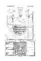
- FIG. 5is a plan view, partially in section, of the cold compress mitten of FIG. 2.
- FIG. 6is a vertical section view taken along the line 66 of FIG. 5.
- FIG. 7is a plan view, partially in section, of the wraparound cold compress device of FIG. 4.
- FIG. 8is a plan view, partially in section, of a modified form of the wrap-around cold compress device of FIG. 4 showing an alternate arrangement for the conducting channel.
- the deviceshown in FIG. 1, is adapted to provide such prompt and effective treatment, and includes an inflatable compress in the form of an inflatable sleeve 1.
- Sleeve 1may be made from any suitable gasimpervions, flexible material, such as rubber; and preferably is made from an inelastic, gas-impervious, flexible material, such as rubberized fabric or polyvinyl plastic material.
- sleeve 1may be surrounded by a restraint made from an inelastic flexible material, such as a fabric material.
- Sleeve 1is slipped over the foreleg of a horse 10 to be treated prior to inflation thereof, and is held in place by the pressure of the inflated device against the horses leg.
- the device of the inventionalso includes a source of compressed refrigerant, such as a tank 2 of liquified refrigerant.
- a source of compressed refrigerantsuch as a tank 2 of liquified refrigerant.
- refrigerantssuch as carbon dioxide, propane, monochlorodifluoromethane, dichlorodifluoromethane, or dichlorotetrafluoroethane may be used in the device of the invention.
- the foregoing refrigerantsare mentioned merely by way of example, and it is understood that the invention embraces the use of any suitable hydrocarbon, halocarbon, or inert compound refrigerant.
- the refrigerant chosenis comparatively non-toxic in accordance with the Underwriters Laboratories classification of refrigerants. Materials such as sulfur dioxide, which is highly toxic, generally are not preferred.
- tank 2is connected to sleeve 1 by a flexible pressure hose 3.
- Hose 3is insulated to limit the absorbtion of heat by the refrigerant prior to entering the channel in the compress wall.
- a manually operable valve 4Interposed between tank 2 and hose 3, and affixed to tank 2, is a manually operable valve 4 which controls the rate of flow of refrigerant from tank 2 into sleeve 1.
- More complex arrangementssuch as an adjustable flow-responsive solenoid valve or even a valve controlled by a computer in response to a multiplicity of parameters affecting the treatment, may be substituted for manual valve 4.
- valve 4controls the temperature of the refrigerant within the compress.
- An optional harness 5may be used to support tank 2 on the patient, thereby providing for portable operation. If portable operation is not necessary or desired, tank 2 or other source of refrigerant may be supported next to the patient in any suitable manner, such as by means of a'wall or floor rack or the like.
- a pressure relief meanssuch as a conventional pres sure relief valve 6 is connected to the wall of sleeve 1 and communicates between the interior thereof and ambient atmosphere.
- Valve 6opens and allows refrigerant vapors to escape from within sleeve 1 when the pressure of the vapors within the compress exceeds a predetermined level. When the pressure of the refrigerant within the sleeve has decreased to the desired level, valve 6 will again close.
- the valvemay be detachably connected by threads or the like so that a given valve readily may be exchanged for another valve responsive to a different pressure level. Also, it is within the scope of the invention to use an adjustable valve. Since the pressure applied to the area being treated is equal to the pressure of the refrigerant within sleeve 1, valve 6 ensures that a substantially constant pressure is applied to the injured area.
- a check valve 7optionally may be interposed in line 3 between valve 4 and compress l to prevent back-flow of refrigerant from the compress should the flow of refrigerant from the source be interrupted.
- valve means 4is provided to allow the operator to control the flow of refrigerant.
- the provision of valve means 4 and check valve 7makes it possible to switch from an exhausted refrigerant tank to a fresh tank without disturbing treatment in progress. This also makes it possible to shut off the flow of refrigerant and allow gradual warm up of the compress to ambient temperature before the compress is removed if it is desired to avoid sudden changes in the temperature applied to the area being treated.
- Check valve 7also serves as a safety feature to prevent deflation and loss of compress 1 should hose 3 be severed or pulled loose as sometimes may happen if an animal is being treated.
- the basic construction of check valve 7may be substantially similar to the structure of the pressure relief valve 6.
- the compressalso may be provided with a quick release valve 8 which communicates between the interior of the compress and the ambient atmosphere. During treatment the valve is maintained in closed position. Opening release valve 8 facilitates rapid deflation of the compress so that it may be quickly and easily removed when the treatment is ended.
- the structure of such valvesis well known to those skilled in the art and accordingly, will not be described in detail here.
- FIG. 1a central portion of the outer wall of sleeve compress I is shown cut away to reveal the underlying conducting channel 9 formed in the inner wall of the compress adjacent the horses leg.
- Channel 9commences at the point where hose 3 enters compress l and winds its way back and forth across substantially the entire inner wall of the sleeve before it ends at the opposite end of the compress near the horses foot where it opens into the interior of the compress.
- the refrigerant which is passed directly into channel 9 from hose 3is thus constrained to traverse substantially the entire area to be treated before passing into the interior of the compress. Accordingly, the cooling effect is distributed substantially uniformly across the entire area being treated.
- valve 4is then opened allowing compressed refrigerant to flow from tank 2 through hose 3 and through channel 9 in the sleeve wall into the interior of sleeve 1, thereby inflating the compress.
- the pressure of the refrigerant within sleeve 1is maintained substantially constant by valve 6.
- the expansion of the refrigerant as it flows from the tank, through the channel and the interior chamber of the compress into ambient atmospherecools the compress.
- the amount of coolingis dependent on the particular refrigerant used and the rate of flow of refrigerant from tank 2 into compress l.
- the refrigerant flow rateis controlled by valve 4, thereby facilitating control of the temperature of the bandage.
- sleeve 1is made from an inelastic material, or is surrounded by an inelastic restraint. Therefore, the compress, when inflated, will have a substantially constant volume. With this arrangement, and since the pressure of the refrigerant within the compress is maintained at a substantially constant level by valve 6, for a particular flow rate of refrigerant, the rate of volitization and expansion and consequently the temperature of the refrigerant within the bandage also will remain substantially constant. The pressure and temperature applied to the area to be treated can thus be accurately controlled by the appropriate selection of valve 6 and regulation of valve 4.
- FIG. 2is a perspective view of an embodiment of the invention in the form of an inflatable mitten for treating the hand, wrist and forearm of a human.
- Mitten compress 21takes the general form of a triple-walled envelope which is open at one end 22 through which the hand and arm of the patient can be extended.
- An inlet fitting 23is provided in communication with a channel formed between the second and third wall layers.
- An outlet fitting 24communicates between the ambient atmosphere and an interior cavity formed in the space between the first and second wall layers.
- a pressure relief valve 26is mounted in outlet fitting 24. Fittings 23 and 24 are secured in position through the respective layers by means of gripping collars 25.
- a quick release valve 28communicating between the ambient atmosphere and the interior cavity between the first and second wall layers. Valve 28 may be opened to facilitate rapid deflation of the compress when desired. Further details of the wall construction of mitten 21 will be explained hereinafter in conjunction with FIGS. 5 and 6.
- FIG. 3is a perspective view of a third embodiment of the instant invention in theform of an inflatable boot adapted to be used to treat the foot and ankle of a human. Except for its L-shape, boot 31 essentially is the same in construction as mitten 21. The foot and leg of the patient are inserted through opening 32 at the top of the boot. Inlet fitting 33, outlet fitting 34, pressure release valve 36 and quick release valve 38 correspond to the fittings and valves 22-28 previously discussed in conjunction with FIG. 2.
- FIG. 4is a perspective view of yet another preferred embodiment of the instant invention which takes the form of an inflatable wrap-around bandage.
- Inflatable bandage 41takes the form of a tri-layer pad with an inlet fitting 43 provided in communication with a channel formed between the second and third layers and a quick release valve 48 and an outlet fitting 44 with a pressure relief valve 46 therein both communicating between the ambient atmosphere and the interior cavity formed in the space between the first and second layers.
- Locking strips 45 on the outside of the bandagemate with corresponding strips (not shown) on the back of the bandage when the bandage is wrapped around a portion of the body of a patient being treated to secure the bandage in position. Suitable locking strips are distributed by the 3M Company, Minneapolis, Minnesota, under the trademark VELCRO.
- the bandageis inflated, the internal pressure which forces the bandage against the body of the patient firmly holds the bandage in place. Further details of the construction of the bandage shown in FIG. 4 will be discussed hereinafter in conjuction with FIGS. 7 and 8.
- FIG. 5is a plan view of the inflatable mitten shown in FIG. 2, and FIG. 6 is a vertical section of the same mitten taken along line 6-6 of FIG. 5.
- each of the walls of mitten 21comprises three layers of flexible thermoplastic material designated respectively from the outside to the inside by reference numerals S0, 51 and 52. Layers 50 and 51 are shown partially cut away in FIG. 5 to reveal the underlying structure. The outer margins of all three of the layers are joined together by means such as heat seal 53 forming a closed interior chamber 54 between layer 50 and layers 51 and 52.
- Layer 51 and layer 52are further joined to each other by a pattern of heat seals 55 which may be visualized as a pair of interlocking combs extending generally over the entire surface of the two layers, whereby a continuous channel 56 extending back and forth between the teeth" of the comb-like seals 55 is formed between layer 51 and layer 52.
- One end of channel 56communicates with inlet fitting 23.
- a hole 57is provided in layer 51 through which channel 56 opens into the interior cavity 54 between layer 50 and layers 51 and 52.
- Refrigerant entering the compress through inlet fitting 23is thus constrained to pass through channel 56 over substantially the entire surface of layer 52 immediately adjacent the hand, wrist and arm of the patient being treated before the refrigerant enters the interior cavity 54 thereby inflating the bandage.
- the cooling effect of the refrigerantis substantially uniformly distributed over the entire surface of the inflatable mitten, and uneven warm and cool spots are largely prevented. Since almost all of the volitization and most of the expansion of the refrigerant will take place in the channel, the channel arrangement also assures that the principal cooling effect will be concentrated immediately adjacent the portion of the patients body being treated thus reducing the absorbtion of heat from the ambient atmosphere and thereby conserving on the amount of refrigerant necessary to maintain the cold compress mitten at a given temperature. Refrigerant vapors in excess of the amount needed to maintain the desired pressure in the inflated compress are gradually released from interior chamber 54 through outlet fitting 24 and pressure relief valve 26.
- FIG. 7is a plan view, partially in section, of the embodiment of the invention shown in FIG. 4 in the form of an inflatable wrap-around bandage.
- Bandage 41comprises three layers of flexible thermoplastic material designated respectively from top to bottom by reference numerals 60, 61 and 62. The outer margins of layer 60 and layer 62 are joined to each other by a heat seal 63 forming an enclosed interior chamber therebetween.
- Layer 61is smaller in size than either of layers 60 and 62 and is positioned in the interior space formed between layers 60 and 62.
- the outer margins of layer 61 and elongated strips extending alternately from the sides into the center region of layer 61are joined to layer 62 by heat seals 65, thereby forming a channel 66 which winds its way back and forth between layers 61 and 62 over substantially the entire surface of layer 61.
- One end of channel 66is in communication with inlet fitting 43.
- the opposite end of channel 66opens through a hole 67 in layer 61 into the interior chamber formed in the space between layers 60 and 62.
- Outlet fitting 44 with pressure relief valve 46 attached thereto and quick release valve 48both communicate through layer 60 between the interior chamber of the inflatable bandage and the ambient atmosphere.
- Locking strips 45are disposed at each end of the wrap-around bandage on opposite sides thereof so that when the bandage is wrapped around a portion of the body of a patient being treated, they will mate and secure the inflatable bandage in position.
- FIG. 8illustrates a modification of the wrap-around cold compress shown in FIGS. 4 and 7 which is designed to concentrate the cooling effect of the refrigerant adjacent a particular area instead of dispersing the cooling effect over substantially the entire face of the bandage.
- the top layer 70 and bottom layer 72 of the inflatable compressare joined to each other around the margins by a heat seal 73 whereby an interior chamber is formed therebetween.
- An interior layer 71corresponding in size to the general dimensions of the area over which it is desired to concentrate the cooling effect of the refrigerant, is disposed in the interior chamber between layers 70 and 72.
- the margins and a portion of the center region of layer 71are joined to inner layer 72 by a heat seal 75 which is arranged in a spiral pattern whereby a spiral channel is formed between layers 71 and 72.
- a refrigerant inlet fitting 47is attached to the inflatable wrap-around bandage in communication with the centrally disposed end of spiral channel 76.
- Layer 7]is cut away at corner 77 to form an outlet for the outer end of channel 76 into the interior chamber between layer and layer 72.
- the general operation ofinflatable bandage 81is essentially the same as the operation of the previously described embodiments except for the fact that the cooling effect of the refrigerant which enters through inlet fitting 47 is more concentrated in the region of the bandage corresponding to the area traversed by spiral channel 76. The remainder of the bandage will exert a somewhat lesser cooling effect on the adjacent portions of the body of the patient being treated.
- the refrigerant conducting channelin a portion of the wall of the compress which is adapted to be disposed remote from the body of the patient being treated so that the patient is not directly subjected to the full cooling effect of the refrigerant.
- the devices of the present inventionare capable of operating throughout a wide range of temperatures and pressures.
- the pressure of the compressshould be slightly higher than the internal pressure of the body fluids of the patient.
- the temperature of the compressshould be somewhere between the body temperature of the patient and the temperature at which the body tissue of the patient will freeze. The precise pressure and temperature applied will of course depend on the injury being treated and on the nature of the patient, whether a human, a horse or another mammal.
- the present inventionprovides a means for promptly and effectively treating injuries in mammals by cooling with pressure which is capable of sustained operation for a substantial period of time.
- the devicedoes not require constant attention, is not messy or inconvenient to use, and is inexpensive in comparison to systems which require external refrigeration equipment.
- the deviceis compact and selfcontained so as to be particularly adapted for portable operation.
- a device for treating mammalscomprising:
- a flexible, inflatable compressadapted to be placed adjacent a body area to be treated
- said compresscomprising a surrounding wall and an inflatable interior cavity formed by said wall;
- said compressfurther comprising an enclosed chan- I nel formed in a portion of the compress wall adapted to conduct a fluid refrigerant over said compress wall portion;
- said channelopening into the inflatable interior cavity of said compress and being connected to an external source of compressed refrigerant whereby refrigerant from said source is constrained to pass over said compress wall portion by traversing said channel before entering the inflatable interior cavity of said compress;
- pressure relief meansconnected to said compress and communicating between the inflatable interior cavity of the compress and the ambient atmosphere for regulating the maximum pressure in the compress whereby the pressure applied to the body area being treated can be controlled.
- halocarbon refrigerantis dichlorodifluoromethane.
- a device as recited in claim 1, wherein said compressis an inflatable, wrap-around bandage.
- a device as recited in claim 1, wherein the compressis an inflatable boot.
- halocarbon refrigerantis dichlorotetrafluoroethane.
- a flexible, inflatable compressadapted to be placed adjacent a body area of a mammal to be treated
- said compresscomprising a surrounding wall and an inflatable interior cavity formed by said wall;
- a portion of said wallcomprising two layers of flexible thermoplastic material joined to each other by a pattern of heat seals;
- said pattern of heat sealsforming an elongated fluid conducting channel extending over said wall portion between said layers;
- one end of said channelopening into the inflatable interior cavity of said compress, and the other end of said channel being adapted to be connected to an external source of compressed refrigerant.
- a flexible, inflatable compressadapted to be placed adjacent a body area to be treated
- said compresscomprising a surrounding wall and an inflatable interior cavity formed by said wall;
- a portion of said wallcomprising two layers of flexible, fluid-impervious material
- one end of said channelopening into the inflatable interior cavity of said compress, and the other end of said channel being adapted to be connected to an external source of compressed refrigerant.
- a compress as recited in claim 27further comprising a pressure relief valve communicating between the inflatable interior cavity of the compress and the external atmosphere.
Landscapes
- Health & Medical Sciences (AREA)
- Life Sciences & Earth Sciences (AREA)
- Veterinary Medicine (AREA)
- General Health & Medical Sciences (AREA)
- Engineering & Computer Science (AREA)
- Animal Behavior & Ethology (AREA)
- Public Health (AREA)
- Biomedical Technology (AREA)
- Heart & Thoracic Surgery (AREA)
- Vascular Medicine (AREA)
- Physics & Mathematics (AREA)
- Thermal Sciences (AREA)
- Wood Science & Technology (AREA)
- Zoology (AREA)
- Thermotherapy And Cooling Therapy Devices (AREA)
Abstract
Description
Claims (28)
Priority Applications (8)
| Application Number | Priority Date | Filing Date | Title |
|---|---|---|---|
| US358899AUS3871381A (en) | 1971-12-30 | 1973-05-10 | Cold compress device |
| GB1982574AGB1467729A (en) | 1973-05-10 | 1974-05-06 | Cold compress device |
| BR371674ABR7403716D0 (en) | 1973-05-10 | 1974-05-07 | DEVICE FOR COLD COMPRESS APPLICATION |
| CA199,350ACA1035229A (en) | 1973-05-10 | 1974-05-07 | Cold compress device |
| AU68725/74AAU475910B2 (en) | 1973-05-10 | 1974-05-08 | Cold compress device |
| FR7416093AFR2228466B1 (en) | 1973-05-10 | 1974-05-09 | |
| JP5168974AJPS5051878A (en) | 1973-05-10 | 1974-05-09 | |
| DE19742422431DE2422431B2 (en) | 1973-05-10 | 1974-05-09 | DEVICE FOR TREATMENT OF SUCKLES |
Applications Claiming Priority (2)
| Application Number | Priority Date | Filing Date | Title |
|---|---|---|---|
| US21397871A | 1971-12-30 | 1971-12-30 | |
| US358899AUS3871381A (en) | 1971-12-30 | 1973-05-10 | Cold compress device |
Publications (1)
| Publication Number | Publication Date |
|---|---|
| US3871381Atrue US3871381A (en) | 1975-03-18 |
Family
ID=26908564
Family Applications (1)
| Application Number | Title | Priority Date | Filing Date |
|---|---|---|---|
| US358899AExpired - LifetimeUS3871381A (en) | 1971-12-30 | 1973-05-10 | Cold compress device |
Country Status (1)
| Country | Link |
|---|---|
| US (1) | US3871381A (en) |
Cited By (82)
| Publication number | Priority date | Publication date | Assignee | Title |
|---|---|---|---|---|
| US4149541A (en)* | 1977-10-06 | 1979-04-17 | Moore-Perk Corporation | Fluid circulating pad |
| US4170998A (en)* | 1975-09-26 | 1979-10-16 | Chattanooga Pharmacal Company | Portable cooling apparatus |
| US4184537A (en)* | 1975-09-26 | 1980-01-22 | Chattanooga Pharmacal Company | Selective heating and cooling apparatus |
| DE3122617A1 (en)* | 1980-06-16 | 1982-04-08 | The Kendall Co., Walpole, Mass. | DEVICE FOR THERAPEUTIC COLD TREATMENT OF A PATIENT |
| US4335726A (en)* | 1980-07-11 | 1982-06-22 | The Kendall Company | Therapeutic device with temperature and pressure control |
| WO1983002562A1 (en)* | 1982-02-01 | 1983-08-04 | Elkins, William | Personal temperature control system |
| US4414969A (en)* | 1981-03-25 | 1983-11-15 | Heyman Arnold M | Wrist restraint |
| US4442834A (en)* | 1981-10-02 | 1984-04-17 | Jobst Institute, Inc. | Pneumatic splint |
| US4466439A (en)* | 1982-02-08 | 1984-08-21 | Moore John H | Device and method for inducing bradycardia |
| US4745922A (en)* | 1986-07-11 | 1988-05-24 | Taylor Kenneth G | Cervical heat transfer and immobilization device |
| US4844072A (en)* | 1985-12-27 | 1989-07-04 | Seabrook Medical Systems, Inc. | Liquid-circulating thermal therapy system |
| US5167227A (en)* | 1991-08-15 | 1992-12-01 | Meserlian Sarkis B | Apparatus for massaging and/or controllably supporting the legs of a horse |
| US5170783A (en)* | 1988-03-24 | 1992-12-15 | Kirby Smith | Cryotherapeutic procedure |
| US5172689A (en)* | 1990-03-01 | 1992-12-22 | Wright Christopher A | Cryogenic sleeve for providing therapeutic compression |
| US5230335A (en)* | 1991-01-23 | 1993-07-27 | Aircast, Inc. | Thermal compress system |
| US5314455A (en)* | 1991-01-23 | 1994-05-24 | Aircast, Inc. | Thermal compress system |
| US5324318A (en)* | 1988-03-24 | 1994-06-28 | Kirby Smith | Cold compress system |
| US5372608A (en)* | 1993-08-12 | 1994-12-13 | Johnson; Bertrand L. | Circulating chilled-fluid therapeutic device |
| US5411541A (en)* | 1993-08-05 | 1995-05-02 | Oansh Designs Ltd. | Portable fluid therapy device |
| US5449379A (en)* | 1993-07-21 | 1995-09-12 | Alternative Compression Technologies, Inc. | Apparatus for applying a desired temperature and pressure to an injured area |
| US5466250A (en)* | 1991-01-23 | 1995-11-14 | Aircast, Inc. | Automatic fluid compress and circulating system |
| US5865841A (en)* | 1995-03-01 | 1999-02-02 | Kolen; Paul T. | Cold therapy apparatus |
| US5913885A (en)* | 1991-05-22 | 1999-06-22 | Life Science Holdings, Inc. | Brain cooling device and method for cooling |
| US5980561A (en)* | 1995-03-01 | 1999-11-09 | Kolen; Paul T. | Applying thermal therapy to living tissue |
| US6030412A (en)* | 1991-05-22 | 2000-02-29 | Life Science Holdings, Inc. | Apparatus and method for cooling the brain, brain stem and associated neurologic tissues |
| US6086609A (en)* | 1997-12-08 | 2000-07-11 | Jay R. Buckley | Controlled cold therapy apparatus |
| US6117164A (en)* | 1997-06-06 | 2000-09-12 | Dj Orthopedics, Llc | Flexible multijoint therapeutic pads |
| US6126683A (en)* | 1999-01-04 | 2000-10-03 | Momtaheni; David M. | Device for therapeutic treatment of the temporomandibular and maxillomandibular region and method for using same |
| US6230501B1 (en)* | 1994-04-14 | 2001-05-15 | Promxd Technology, Inc. | Ergonomic systems and methods providing intelligent adaptive surfaces and temperature control |
| USD445223S1 (en) | 2000-10-12 | 2001-07-17 | Tina Butler | Horse ice pack |
| US6277143B1 (en)* | 1991-05-22 | 2001-08-21 | Life Science Holdings, Inc. | Brain cooling apparatus and method for cooling the brain |
| EP1038510A3 (en)* | 1999-03-26 | 2002-04-17 | Karbix Establishment | Cooling bandage |
| US6695872B2 (en) | 2000-01-28 | 2004-02-24 | Coolsystems, Inc. | Therapy component of an animate body heat exchanger and method of manufacturing such component |
| US20040064170A1 (en)* | 2002-09-30 | 2004-04-01 | Radons Stephen W. | Rapid induction of mild hypothermia |
| US20040064169A1 (en)* | 2002-09-30 | 2004-04-01 | Briscoe Kathleen E. | User interface for medical device |
| US20040064342A1 (en)* | 2002-09-30 | 2004-04-01 | Browne David W. | Health care protocols |
| US20040064171A1 (en)* | 2002-09-30 | 2004-04-01 | Briscoe Kathleen E. | Feedback system for rapid induction of mild hypothermia |
| US20040152954A1 (en)* | 2003-01-31 | 2004-08-05 | Christopher Pearce | Menu-driven medical device configuration |
| US20040200481A1 (en)* | 2003-04-01 | 2004-10-14 | Aaron Chapman | Harnesses |
| US20040214148A1 (en)* | 2003-04-22 | 2004-10-28 | Salvino Robert J. | Updating health care protocols |
| US20050075592A1 (en)* | 2003-10-01 | 2005-04-07 | Mark Garon | Bandage cooling apparatus and method of using same |
| US20050101911A1 (en)* | 2002-12-23 | 2005-05-12 | Chester Steven M. | Coolant control for rapid induction of mild hypothermia |
| US20050256556A1 (en)* | 2004-05-17 | 2005-11-17 | Coolsystems, Inc. | Modular apparatus for therapy of an animate body |
| US20050284417A1 (en)* | 2004-06-25 | 2005-12-29 | Animal Capture Equipment, Inc. | Device for cooling and moistening sea mammal |
| US20060137699A1 (en)* | 2004-12-23 | 2006-06-29 | Moore Mark P | Providing data destination information to a medical device |
| US20060155350A1 (en)* | 2005-01-10 | 2006-07-13 | Lu Nan C | Pressure adjustable structure for ice compress |
| US7211104B2 (en) | 2002-10-08 | 2007-05-01 | Vital Wear, Inc. | Contrast therapy system and method |
| US7219449B1 (en) | 1999-05-03 | 2007-05-22 | Promdx Technology, Inc. | Adaptively controlled footwear |
| WO2007067129A1 (en)* | 2005-12-06 | 2007-06-14 | Dignitana Ab | Method and device for controlling the temperature of local regions of a patient's body |
| US20090066079A1 (en)* | 2007-09-12 | 2009-03-12 | Coolsystems, Inc. | Make-brake connector assembly with opposing latches |
| US20100030306A1 (en)* | 2002-10-08 | 2010-02-04 | Howard Edelman | Therapeutic Cranial Wrap for a Contrast Therapy System |
| US7658205B1 (en) | 2002-12-19 | 2010-02-09 | Vitalwear, Inc. | Systems for a fluid circuit coupler |
| US7694693B1 (en) | 2002-10-08 | 2010-04-13 | Vitalwear, Inc. | Mixing valve for a contrast therapy system |
| GB2422769B (en)* | 2005-01-14 | 2010-05-19 | Npb Medical Ltd | Heat therapy garment |
| US20100145421A1 (en)* | 2008-12-05 | 2010-06-10 | Coolsystems, Inc. | Therapeutic Cooling and/or Heating System Including A Thermo-Conductive Material |
| US20100139294A1 (en)* | 2008-12-05 | 2010-06-10 | Coolsystems, Inc. | Cooling System Having A Bypass Valve To Regulate Fluid Flow |
| US7837638B2 (en) | 2007-02-13 | 2010-11-23 | Coolsystems, Inc. | Flexible joint wrap |
| US20110098792A1 (en)* | 2009-10-22 | 2011-04-28 | Lowe Mark H | Therapeutic wrap |
| US20110106023A1 (en)* | 2009-11-04 | 2011-05-05 | Lowe Mark H | System for providing treatment to a mammal |
| US8052628B1 (en) | 2002-10-08 | 2011-11-08 | Vitalwear, Inc. | Spinal column brace for a contrast therapy system |
| US20120117997A1 (en)* | 2010-11-15 | 2012-05-17 | Coleman Stephen M | Body Core Thermo-regulation Cooling Sleeve |
| US20120232447A1 (en)* | 2011-03-07 | 2012-09-13 | Charles Gordon | Systems and methods for deep vein thrombosis prophylaxis |
| US20130038457A1 (en)* | 2005-07-14 | 2013-02-14 | Zoll Circulation, Inc. | System and method for leak detection in external cooling pad |
| US8425579B1 (en) | 2002-10-08 | 2013-04-23 | Vitalwear, Inc. | Therapeutic knee brace for a contrast therapy system |
| US20130123886A1 (en)* | 2011-11-15 | 2013-05-16 | Gary Chiu | Wearable horse cooling device |
| US20130131763A1 (en)* | 2011-11-18 | 2013-05-23 | Gary Chiu | Method for mounting a wearable horse cooling device |
| US8465444B1 (en)* | 2010-04-09 | 2013-06-18 | Medergo Associates, Llc | Laminitis treatment system and method |
| US20130245729A1 (en)* | 2012-03-13 | 2013-09-19 | Medical Technology Inc. | Cold therapy systems and methods |
| US8597217B2 (en) | 2010-12-30 | 2013-12-03 | Coolsystems, Inc. | Reinforced therapeutic wrap and method |
| US20150335469A1 (en)* | 2012-06-22 | 2015-11-26 | Physiolab Technologies Limited | Thermoregulation interface pack and assembly |
| GB2536637A (en)* | 2015-03-23 | 2016-09-28 | Talar-Made Ltd | An apparatus and method for supporting at least a part of a person and a method of manufacturing an apparatus |
| US9615967B2 (en) | 2010-12-30 | 2017-04-11 | Coolsystems, Inc. | Reinforced therapeutic wrap and method |
| EP2999441B1 (en)* | 2013-05-23 | 2017-09-20 | Physiolab Technologies Limited | Compression and thermoregulation device |
| US9872812B2 (en) | 2012-09-28 | 2018-01-23 | Kpr U.S., Llc | Residual pressure control in a compression device |
| US10456320B2 (en) | 2013-10-01 | 2019-10-29 | Coolsystems, Inc. | Hand and foot wraps |
| US10463565B2 (en) | 2011-06-17 | 2019-11-05 | Coolsystems, Inc. | Adjustable patient therapy device |
| WO2020102530A3 (en)* | 2018-11-14 | 2020-08-13 | Joseph Jones | Portable limb, head, chest cooling system |
| US10859295B2 (en) | 2016-04-13 | 2020-12-08 | ZeoThermal Technologies, LLC | Cooling and heating platform |
| CN112972104A (en)* | 2021-02-05 | 2021-06-18 | 南方医科大学南方医院 | Low-temperature noninvasive protection device for limb trauma |
| US11638675B2 (en) | 2018-11-07 | 2023-05-02 | Zenith Technical Innovations, Llc | System and method for heat or cold therapy and compression therapy |
| US11672693B2 (en) | 2014-08-05 | 2023-06-13 | Avent, Inc. | Integrated multisectional heat exchanger |
| CN117045426A (en)* | 2023-07-19 | 2023-11-14 | 重庆市九龙坡职业教育中心 | Portable intelligent air bag ice compress device |
Citations (5)
| Publication number | Priority date | Publication date | Assignee | Title |
|---|---|---|---|---|
| US127875A (en)* | 1872-06-11 | Geoege j | ||
| US3000190A (en)* | 1959-07-15 | 1961-09-19 | Stark Virgil | Apparatus and wearing apparel for body refrigeration |
| US3017888A (en)* | 1959-02-05 | 1962-01-23 | Louis I Weiner | System for cooling a hot weather face mask |
| US3186404A (en)* | 1961-06-21 | 1965-06-01 | William J Gardner | Pressure device and system for treating body members |
| US3628537A (en)* | 1970-04-06 | 1971-12-21 | Wilbur C Berndt | Self-retaining cold wrap |
- 1973
- 1973-05-10USUS358899Apatent/US3871381A/ennot_activeExpired - Lifetime
Patent Citations (5)
| Publication number | Priority date | Publication date | Assignee | Title |
|---|---|---|---|---|
| US127875A (en)* | 1872-06-11 | Geoege j | ||
| US3017888A (en)* | 1959-02-05 | 1962-01-23 | Louis I Weiner | System for cooling a hot weather face mask |
| US3000190A (en)* | 1959-07-15 | 1961-09-19 | Stark Virgil | Apparatus and wearing apparel for body refrigeration |
| US3186404A (en)* | 1961-06-21 | 1965-06-01 | William J Gardner | Pressure device and system for treating body members |
| US3628537A (en)* | 1970-04-06 | 1971-12-21 | Wilbur C Berndt | Self-retaining cold wrap |
Cited By (107)
| Publication number | Priority date | Publication date | Assignee | Title |
|---|---|---|---|---|
| US4170998A (en)* | 1975-09-26 | 1979-10-16 | Chattanooga Pharmacal Company | Portable cooling apparatus |
| US4184537A (en)* | 1975-09-26 | 1980-01-22 | Chattanooga Pharmacal Company | Selective heating and cooling apparatus |
| US4149541A (en)* | 1977-10-06 | 1979-04-17 | Moore-Perk Corporation | Fluid circulating pad |
| DE3122617A1 (en)* | 1980-06-16 | 1982-04-08 | The Kendall Co., Walpole, Mass. | DEVICE FOR THERAPEUTIC COLD TREATMENT OF A PATIENT |
| US4338944A (en)* | 1980-06-16 | 1982-07-13 | The Kendall Company | Therapeutic device |
| US4335726A (en)* | 1980-07-11 | 1982-06-22 | The Kendall Company | Therapeutic device with temperature and pressure control |
| US4414969A (en)* | 1981-03-25 | 1983-11-15 | Heyman Arnold M | Wrist restraint |
| US4442834A (en)* | 1981-10-02 | 1984-04-17 | Jobst Institute, Inc. | Pneumatic splint |
| WO1983002562A1 (en)* | 1982-02-01 | 1983-08-04 | Elkins, William | Personal temperature control system |
| US4466439A (en)* | 1982-02-08 | 1984-08-21 | Moore John H | Device and method for inducing bradycardia |
| US4844072A (en)* | 1985-12-27 | 1989-07-04 | Seabrook Medical Systems, Inc. | Liquid-circulating thermal therapy system |
| US4745922A (en)* | 1986-07-11 | 1988-05-24 | Taylor Kenneth G | Cervical heat transfer and immobilization device |
| US5170783A (en)* | 1988-03-24 | 1992-12-15 | Kirby Smith | Cryotherapeutic procedure |
| US5324318A (en)* | 1988-03-24 | 1994-06-28 | Kirby Smith | Cold compress system |
| US5172689A (en)* | 1990-03-01 | 1992-12-22 | Wright Christopher A | Cryogenic sleeve for providing therapeutic compression |
| US5466250A (en)* | 1991-01-23 | 1995-11-14 | Aircast, Inc. | Automatic fluid compress and circulating system |
| US5230335A (en)* | 1991-01-23 | 1993-07-27 | Aircast, Inc. | Thermal compress system |
| US5314455A (en)* | 1991-01-23 | 1994-05-24 | Aircast, Inc. | Thermal compress system |
| US6030412A (en)* | 1991-05-22 | 2000-02-29 | Life Science Holdings, Inc. | Apparatus and method for cooling the brain, brain stem and associated neurologic tissues |
| US6277143B1 (en)* | 1991-05-22 | 2001-08-21 | Life Science Holdings, Inc. | Brain cooling apparatus and method for cooling the brain |
| US5913885A (en)* | 1991-05-22 | 1999-06-22 | Life Science Holdings, Inc. | Brain cooling device and method for cooling |
| US5167227A (en)* | 1991-08-15 | 1992-12-01 | Meserlian Sarkis B | Apparatus for massaging and/or controllably supporting the legs of a horse |
| US5449379A (en)* | 1993-07-21 | 1995-09-12 | Alternative Compression Technologies, Inc. | Apparatus for applying a desired temperature and pressure to an injured area |
| US5411541A (en)* | 1993-08-05 | 1995-05-02 | Oansh Designs Ltd. | Portable fluid therapy device |
| US5372608A (en)* | 1993-08-12 | 1994-12-13 | Johnson; Bertrand L. | Circulating chilled-fluid therapeutic device |
| US6230501B1 (en)* | 1994-04-14 | 2001-05-15 | Promxd Technology, Inc. | Ergonomic systems and methods providing intelligent adaptive surfaces and temperature control |
| US5980561A (en)* | 1995-03-01 | 1999-11-09 | Kolen; Paul T. | Applying thermal therapy to living tissue |
| US5865841A (en)* | 1995-03-01 | 1999-02-02 | Kolen; Paul T. | Cold therapy apparatus |
| US6117164A (en)* | 1997-06-06 | 2000-09-12 | Dj Orthopedics, Llc | Flexible multijoint therapeutic pads |
| US6352550B1 (en) | 1997-06-06 | 2002-03-05 | Dj Orthopedics, Llc | Flexible multijoint therapeutic pads |
| US6086609A (en)* | 1997-12-08 | 2000-07-11 | Jay R. Buckley | Controlled cold therapy apparatus |
| US6126683A (en)* | 1999-01-04 | 2000-10-03 | Momtaheni; David M. | Device for therapeutic treatment of the temporomandibular and maxillomandibular region and method for using same |
| EP1038510A3 (en)* | 1999-03-26 | 2002-04-17 | Karbix Establishment | Cooling bandage |
| US7219449B1 (en) | 1999-05-03 | 2007-05-22 | Promdx Technology, Inc. | Adaptively controlled footwear |
| US6695872B2 (en) | 2000-01-28 | 2004-02-24 | Coolsystems, Inc. | Therapy component of an animate body heat exchanger and method of manufacturing such component |
| USD445223S1 (en) | 2000-10-12 | 2001-07-17 | Tina Butler | Horse ice pack |
| US7179279B2 (en) | 2002-09-30 | 2007-02-20 | Medtronic Physio Control Corp. | Rapid induction of mild hypothermia |
| US20040064342A1 (en)* | 2002-09-30 | 2004-04-01 | Browne David W. | Health care protocols |
| US20040064171A1 (en)* | 2002-09-30 | 2004-04-01 | Briscoe Kathleen E. | Feedback system for rapid induction of mild hypothermia |
| US20040064169A1 (en)* | 2002-09-30 | 2004-04-01 | Briscoe Kathleen E. | User interface for medical device |
| US7087075B2 (en) | 2002-09-30 | 2006-08-08 | Medtronic Emergency Response Systems, Inc. | Feedback system for rapid induction of mild hypothermia |
| WO2004030586A3 (en)* | 2002-09-30 | 2004-10-28 | Medtronic Physio Control Corp | Rapid induction of mild hypothermia |
| US20040064170A1 (en)* | 2002-09-30 | 2004-04-01 | Radons Stephen W. | Rapid induction of mild hypothermia |
| US8226698B2 (en) | 2002-10-08 | 2012-07-24 | Vitalwear, Inc. | Therapeutic cranial wrap for a contrast therapy system |
| US7694693B1 (en) | 2002-10-08 | 2010-04-13 | Vitalwear, Inc. | Mixing valve for a contrast therapy system |
| US20100030306A1 (en)* | 2002-10-08 | 2010-02-04 | Howard Edelman | Therapeutic Cranial Wrap for a Contrast Therapy System |
| US8052628B1 (en) | 2002-10-08 | 2011-11-08 | Vitalwear, Inc. | Spinal column brace for a contrast therapy system |
| US7211104B2 (en) | 2002-10-08 | 2007-05-01 | Vital Wear, Inc. | Contrast therapy system and method |
| US8425579B1 (en) | 2002-10-08 | 2013-04-23 | Vitalwear, Inc. | Therapeutic knee brace for a contrast therapy system |
| US7658205B1 (en) | 2002-12-19 | 2010-02-09 | Vitalwear, Inc. | Systems for a fluid circuit coupler |
| US7056282B2 (en) | 2002-12-23 | 2006-06-06 | Medtronic Emergency Response Systems, Inc. | Coolant control for rapid induction of mild hypothermia |
| US20050101911A1 (en)* | 2002-12-23 | 2005-05-12 | Chester Steven M. | Coolant control for rapid induction of mild hypothermia |
| US20040152954A1 (en)* | 2003-01-31 | 2004-08-05 | Christopher Pearce | Menu-driven medical device configuration |
| US20040200481A1 (en)* | 2003-04-01 | 2004-10-14 | Aaron Chapman | Harnesses |
| US7726312B2 (en)* | 2003-04-01 | 2010-06-01 | Draeger Safety Uk Limited | Harnesses |
| US20100200624A1 (en)* | 2003-04-01 | 2010-08-12 | Draeger Safety Uk Limited | Harnesses |
| US8474457B2 (en) | 2003-04-01 | 2013-07-02 | Draeger Safety Uk Limited | Harnesses |
| US20040214148A1 (en)* | 2003-04-22 | 2004-10-28 | Salvino Robert J. | Updating health care protocols |
| US6923777B2 (en)* | 2003-10-01 | 2005-08-02 | Multivet International Inc. | Bandage cooling apparatus and method of using same |
| US20050075592A1 (en)* | 2003-10-01 | 2005-04-07 | Mark Garon | Bandage cooling apparatus and method of using same |
| US20090005841A1 (en)* | 2004-05-17 | 2009-01-01 | Tamara Lynn Schirrmacher | Modular apparatus for therapy of an animate body |
| US20050256556A1 (en)* | 2004-05-17 | 2005-11-17 | Coolsystems, Inc. | Modular apparatus for therapy of an animate body |
| US7896910B2 (en) | 2004-05-17 | 2011-03-01 | Coolsystems, Inc. | Modular apparatus for therapy of an animate body |
| US20110152983A1 (en)* | 2004-05-17 | 2011-06-23 | Tamara Lynn Schirrmacher | Modular apparatus for therapy of an animate body |
| US11013635B2 (en) | 2004-05-17 | 2021-05-25 | Coolsystems, Inc. | Modular apparatus for therapy of an animate body |
| US20050284417A1 (en)* | 2004-06-25 | 2005-12-29 | Animal Capture Equipment, Inc. | Device for cooling and moistening sea mammal |
| US20060137699A1 (en)* | 2004-12-23 | 2006-06-29 | Moore Mark P | Providing data destination information to a medical device |
| US20060155350A1 (en)* | 2005-01-10 | 2006-07-13 | Lu Nan C | Pressure adjustable structure for ice compress |
| GB2422769B (en)* | 2005-01-14 | 2010-05-19 | Npb Medical Ltd | Heat therapy garment |
| US9615966B2 (en)* | 2005-07-14 | 2017-04-11 | Zoll Circulation, Inc. | System and method for leak detection in external cooling pad |
| US20130038457A1 (en)* | 2005-07-14 | 2013-02-14 | Zoll Circulation, Inc. | System and method for leak detection in external cooling pad |
| US8696723B2 (en) | 2005-07-14 | 2014-04-15 | Zoll Circulation, Inc. | System and method for leak detection in external cooling pad |
| US20090254159A1 (en)* | 2005-12-06 | 2009-10-08 | Procella Ab | Method and Device for Controlling the Temperature of Local Regions of a Patient's Body |
| WO2007067129A1 (en)* | 2005-12-06 | 2007-06-14 | Dignitana Ab | Method and device for controlling the temperature of local regions of a patient's body |
| US20110028873A1 (en)* | 2007-02-13 | 2011-02-03 | Miros Robert H J | Flexible joint wrap |
| US7837638B2 (en) | 2007-02-13 | 2010-11-23 | Coolsystems, Inc. | Flexible joint wrap |
| US9980844B2 (en) | 2007-02-13 | 2018-05-29 | Coolsystems, Inc. | Flexible joint wrap |
| US7731244B2 (en) | 2007-09-12 | 2010-06-08 | Coolsystems, Inc. | Make-brake connector assembly with opposing latches |
| US20090066079A1 (en)* | 2007-09-12 | 2009-03-12 | Coolsystems, Inc. | Make-brake connector assembly with opposing latches |
| US20100139294A1 (en)* | 2008-12-05 | 2010-06-10 | Coolsystems, Inc. | Cooling System Having A Bypass Valve To Regulate Fluid Flow |
| US20100145421A1 (en)* | 2008-12-05 | 2010-06-10 | Coolsystems, Inc. | Therapeutic Cooling and/or Heating System Including A Thermo-Conductive Material |
| US20110098792A1 (en)* | 2009-10-22 | 2011-04-28 | Lowe Mark H | Therapeutic wrap |
| US9943437B2 (en) | 2009-10-22 | 2018-04-17 | Coolsystems, Inc. | Temperature and flow control methods in a thermal therapy device |
| US8715330B2 (en) | 2009-10-22 | 2014-05-06 | Coolsystems, Inc. | Temperature and flow control methods in a thermal therapy device |
| US20110106023A1 (en)* | 2009-11-04 | 2011-05-05 | Lowe Mark H | System for providing treatment to a mammal |
| US8465444B1 (en)* | 2010-04-09 | 2013-06-18 | Medergo Associates, Llc | Laminitis treatment system and method |
| US20120117997A1 (en)* | 2010-11-15 | 2012-05-17 | Coleman Stephen M | Body Core Thermo-regulation Cooling Sleeve |
| US9615967B2 (en) | 2010-12-30 | 2017-04-11 | Coolsystems, Inc. | Reinforced therapeutic wrap and method |
| US8597217B2 (en) | 2010-12-30 | 2013-12-03 | Coolsystems, Inc. | Reinforced therapeutic wrap and method |
| US11547625B2 (en) | 2010-12-30 | 2023-01-10 | Avent, Inc. | Reinforced therapeutic wrap and method |
| US20120232447A1 (en)* | 2011-03-07 | 2012-09-13 | Charles Gordon | Systems and methods for deep vein thrombosis prophylaxis |
| US10463565B2 (en) | 2011-06-17 | 2019-11-05 | Coolsystems, Inc. | Adjustable patient therapy device |
| US20130123886A1 (en)* | 2011-11-15 | 2013-05-16 | Gary Chiu | Wearable horse cooling device |
| US20130131763A1 (en)* | 2011-11-18 | 2013-05-23 | Gary Chiu | Method for mounting a wearable horse cooling device |
| US9566187B2 (en)* | 2012-03-13 | 2017-02-14 | Breg, Inc. | Cold therapy systems and methods |
| US20130245729A1 (en)* | 2012-03-13 | 2013-09-19 | Medical Technology Inc. | Cold therapy systems and methods |
| US20150335469A1 (en)* | 2012-06-22 | 2015-11-26 | Physiolab Technologies Limited | Thermoregulation interface pack and assembly |
| US9872812B2 (en) | 2012-09-28 | 2018-01-23 | Kpr U.S., Llc | Residual pressure control in a compression device |
| EP2999441B1 (en)* | 2013-05-23 | 2017-09-20 | Physiolab Technologies Limited | Compression and thermoregulation device |
| US10456320B2 (en) | 2013-10-01 | 2019-10-29 | Coolsystems, Inc. | Hand and foot wraps |
| US11672693B2 (en) | 2014-08-05 | 2023-06-13 | Avent, Inc. | Integrated multisectional heat exchanger |
| GB2536637A (en)* | 2015-03-23 | 2016-09-28 | Talar-Made Ltd | An apparatus and method for supporting at least a part of a person and a method of manufacturing an apparatus |
| US10859295B2 (en) | 2016-04-13 | 2020-12-08 | ZeoThermal Technologies, LLC | Cooling and heating platform |
| US11638675B2 (en) | 2018-11-07 | 2023-05-02 | Zenith Technical Innovations, Llc | System and method for heat or cold therapy and compression therapy |
| WO2020102530A3 (en)* | 2018-11-14 | 2020-08-13 | Joseph Jones | Portable limb, head, chest cooling system |
| CN112972104A (en)* | 2021-02-05 | 2021-06-18 | 南方医科大学南方医院 | Low-temperature noninvasive protection device for limb trauma |
| CN117045426A (en)* | 2023-07-19 | 2023-11-14 | 重庆市九龙坡职业教育中心 | Portable intelligent air bag ice compress device |
Similar Documents
| Publication | Publication Date | Title |
|---|---|---|
| US3871381A (en) | Cold compress device | |
| US5449379A (en) | Apparatus for applying a desired temperature and pressure to an injured area | |
| US4335726A (en) | Therapeutic device with temperature and pressure control | |
| US4338944A (en) | Therapeutic device | |
| US5080089A (en) | Therapeutic apparatus applying compression and a nonambient temperature fluid | |
| US5407421A (en) | Compressive brace | |
| US7666213B2 (en) | Apparatus for altering the body temperature of a patient | |
| US4231355A (en) | Device for air-massage | |
| US7303579B2 (en) | Apparatus for altering the body temperature of a patient | |
| US5913886A (en) | Body temperature control system and method of temperature control | |
| US3717145A (en) | Cold pressure bandage | |
| US20180153736A1 (en) | Apparatus for providing a heating or cooling effect | |
| EP0979060B1 (en) | Improved apparatus for the core body warming of mammals experiencing hypothermia | |
| US3916911A (en) | Portable cooling apparatus | |
| CA2970064C (en) | Portable therapeutic system using hot or cold temperature | |
| WO1999030607A3 (en) | Method and apparatus to medically treat soft tissue damage, lymphedema and edema | |
| JPH1099387A (en) | Surface pad system for surgical table | |
| JP2014516743A (en) | Compression device | |
| JP2000516518A (en) | Application of thermal treatment | |
| CN107874973B (en) | Massage physiotherapy equipment | |
| EP0026799A1 (en) | Pressure bag essembly for air-massage | |
| DE2422431A1 (en) | DEVICE FOR TREATMENT OF SUCKLES | |
| CN111053638A (en) | Sprain disposal bag | |
| JP4610162B2 (en) | Cooling / heating system | |
| WO2024180380A1 (en) | Cryogenic bed |
Legal Events
| Date | Code | Title | Description |
|---|---|---|---|
| AS | Assignment | Owner name:CRYO-MED DEVICES, INC., NEW JERSEY Free format text:SECURITY INTEREST;ASSIGNOR:DE VRIES, ROBERT J.;REEL/FRAME:003824/0137 Effective date:19801231 | |
| AS | Assignment | Owner name:NEVADA NATIONAL CO., A CORP. OF IA. Free format text:ASSIGNMENT OF ASSIGNORS INTEREST.;ASSIGNOR:NEVADA NATIONAL BANK;REEL/FRAME:003828/0736 Effective date:19810204 | |
| STCF | Information on status: patent grant | Free format text:PATENTED FILE - (OLD CASE ADDED FOR FILE TRACKING PURPOSES) | |
| AS | Assignment | Owner name:CRYOMED CORPORATION, 33 EGLANTINE AVENUE, PENNINGT Free format text:ASSIGNMENT OF ASSIGNORS INTEREST.;ASSIGNOR:CRYO-MED DEVICES, INC.;REEL/FRAME:004569/0488 Effective date:19830926 | |
| AS | Assignment | Owner name:TDH II LIMITED, A PA LIMITED PARTNERSHIP Free format text:ASSIGNMENT OF ASSIGNORS INTEREST.;ASSIGNOR:CRYOMED CORPORATION, A CORP. OF DE;REEL/FRAME:005253/0176 Effective date:19890401 |