US3863181A - Mode suppressor for strip transmission lines - Google Patents
Mode suppressor for strip transmission linesDownload PDFInfo
- Publication number
- US3863181A US3863181AUS421392AUS42139273AUS3863181AUS 3863181 AUS3863181 AUS 3863181AUS 421392 AUS421392 AUS 421392AUS 42139273 AUS42139273 AUS 42139273AUS 3863181 AUS3863181 AUS 3863181A
- Authority
- US
- United States
- Prior art keywords
- groove
- shield
- dielectric
- dielectric substrate
- ground plane
- Prior art date
- Legal status (The legal status is an assumption and is not a legal conclusion. Google has not performed a legal analysis and makes no representation as to the accuracy of the status listed.)
- Expired - Lifetime
Links
- 230000005540biological transmissionEffects0.000titleclaimsabstractdescription38
- 239000000758substrateSubstances0.000claimsabstractdescription37
- 239000010409thin filmSubstances0.000claimsabstractdescription16
- 239000004020conductorSubstances0.000claimsdescription35
- 230000001629suppressionEffects0.000abstractdescription12
- 238000013461designMethods0.000abstractdescription3
- 230000008878couplingEffects0.000description3
- 238000010168coupling processMethods0.000description3
- 238000005859coupling reactionMethods0.000description3
- 239000003989dielectric materialSubstances0.000description3
- 230000005672electromagnetic fieldEffects0.000description3
- 239000010408filmSubstances0.000description2
- 239000004615ingredientSubstances0.000description2
- 239000002184metalSubstances0.000description2
- 229910052751metalInorganic materials0.000description2
- 238000000034methodMethods0.000description2
- ZOXJGFHDIHLPTG-UHFFFAOYSA-NBoronChemical compound[B]ZOXJGFHDIHLPTG-UHFFFAOYSA-N0.000description1
- 239000000956alloySubstances0.000description1
- 229910045601alloyInorganic materials0.000description1
- 238000010420art techniqueMethods0.000description1
- 229910052796boronInorganic materials0.000description1
- 239000003795chemical substances by applicationSubstances0.000description1
- 238000004891communicationMethods0.000description1
- 238000007796conventional methodMethods0.000description1
- 238000005260corrosionMethods0.000description1
- 230000007797corrosionEffects0.000description1
- 238000009792diffusion processMethods0.000description1
- 230000008020evaporationEffects0.000description1
- 238000001704evaporationMethods0.000description1
- 239000011810insulating materialSubstances0.000description1
- 238000005468ion implantationMethods0.000description1
- 238000004519manufacturing processMethods0.000description1
- 239000000463materialSubstances0.000description1
- 239000007769metal materialSubstances0.000description1
- 229910052758niobiumInorganic materials0.000description1
- 239000010955niobiumSubstances0.000description1
- GUCVJGMIXFAOAE-UHFFFAOYSA-Nniobium atomChemical compound[Nb]GUCVJGMIXFAOAE-UHFFFAOYSA-N0.000description1
- 230000035515penetrationEffects0.000description1
- 238000012545processingMethods0.000description1
- 230000000644propagated effectEffects0.000description1
- 230000005855radiationEffects0.000description1
- 239000007787solidSubstances0.000description1
- 238000004544sputter depositionMethods0.000description1
- 239000010902strawSubstances0.000description1
Images

Classifications
- H—ELECTRICITY
- H01—ELECTRIC ELEMENTS
- H01P—WAVEGUIDES; RESONATORS, LINES, OR OTHER DEVICES OF THE WAVEGUIDE TYPE
- H01P1/00—Auxiliary devices
- H01P1/16—Auxiliary devices for mode selection, e.g. mode suppression or mode promotion; for mode conversion
- H01P1/162—Auxiliary devices for mode selection, e.g. mode suppression or mode promotion; for mode conversion absorbing spurious or unwanted modes of propagation
Definitions
- a waveguide mode suppressing structurewhich selectively suppresses the waveguide modes over a certain frequency range and also physically provides support for a dielectric sub- [52] US. Cl. 333/96, 333/98 M t t Th tru ture has at least one groove, having an [5 I] Int. CI.
- At least one resistive thin filmmay be deposited on the FOREIGN PATENTS OR APPLICATIONS dielectric substrate in the vicinity of the groove to in- 590302 7/1947 Great Britain 333/98 M crease Suppression capability 1,931,228 1/1970 Germany 333/96 7 Claims, 4 Drawing Figures DIELECTRIC 207 ⁇ 203 /2l3 /V///// ////W 2 o I r 2
- FIG. 2(PRIOR ART) FIG. 2
- strip transmission linesincluding stripline and microstrip lines and more specifically to mode suppression techniques for such lines. These lines are used for building passive networks and for interconnecting active devices in hybrid integrated circuits.
- strip transmission linesare planar structures containing two parallel conductors; one conductor is called a ground plane and the other is called a conductor strip. A number of conductor strips may be used with a single ground plane to produce a plurality of circuits.
- a striplineis a'strip transmission line in which the ground plane and dielectric substrate which supports the conductor strip are separated from each other by a material whose dielectric constant is less than that of the substrate.
- a microstrip lineis a strip transmission line in which the ground plane and strip conductor are separated from each other only by the solid dielectric material upon which the strip conductor is mounted.
- Strip transmission linesare often shielded by a conducting channel which suppresses radiation' from the transmission lines and reduces coupling between circuits.
- the surrounding channel and the ground planeform a waveguide-like structure and undesired waveguide modes may be excited above a certain cutoff frequency.
- These spurious waveguide modescan be suppressed in accordance with prior art techniques by dimensioning the channel width and height to be less than one-half of the electrical wavelength at the operating frequency of the strip transmission lines.
- this limitation on channel sizeimposes restrictions on the number of strip conductors which may be deposited on a given substrate.
- undesired waveguide modesexcite spurious resonances which may also limit the performance of nonlinear devices associated with the strip transmission line. It is therefore desirable in order to minimize circuit losses to use large cross-section channels and to provide suitable mode suppression without restricting the channel dimensions.
- the inventionis directed in part to modifying the shielding structure which encloses the transmission lines by placing at least one groove of approximate electrical depth one-quarter A, where A is the wavelength at the operating frequency of the transmission line, in the side wall of the channel. This groove runs along the entire length of the channel. It may also support the dielectric substrate to which the conductor strip is affixed.
- the waveguide mode suppression technique disclosedis suitable for building compact, economical, solid-state sources and frequency converters in the microwave and millimeter-wave frequency range.
- the selective suppression of undesired waveguide modespermits substantial increase of channel dimensions thereby allowing great freedom in microstrip circuit design.
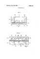
- FIG. 1is a cross-section view of a shielded stripline structure found in the prior art
- FIG. 2is a cross-section view of a stripline structure illustrating side wall grooves and resistive thin films in accordance with the invention
- FIG. 3is a cross-section view of a microstrip structure in accordance with the invention.
- FIG. 4is a cross-section view of a stripline structure with vertically oriented grooves in accordance with the invention.
- FIG. 1shows a cross-section view of shielded stripline structure known in the prior art.
- a rectangular conducting shieldencloses a dielectric substrate 101, a conductor strip 102 which is affixed to the substrate 101 and a ground plane 105.
- the substrate 101is held in place by supports 103 and 104 in opposite side walls of shield 100. These supports perform no electromagnetic function and only provide physical support for the dielectric substrate.
- waveguide mode suppressionis accomplished by restricting both the height h and width w of shield 100 to less than half an electrical wavelength at the operating frequency of the stripline.
- the shielding structure which encloses the transmission linesis modified by placing at least one groove of approximate electrical depth one-quarter 7t, where A is the wavelength at the operating frequency of the transmission line in the side wall of the channel.
- This grooveruns along the length of the channel and may support the dielectric substrate to which the conductor strip is affixed.
- a corresponding plurality of grooves or tapered grooves of appropriate depthsmay be used.
- the operating frequencyis a single fixed frequency.
- the approximate center of the bandis taken as the operating frequency of the circuit.
- the groovestores electromagnetic energy. Electromagnetic fields are excited inside the groove and at a certain frequency, couple in accordance with Maxwells equations, with fields outside the groove, causing the groove to present a high impedance to surface currents in the shield side walls. These currents and their undesired waveguide modes are thereby suppressed.
- the fundamental modeis the lowest order mode which propagates in the channel in the absence of a dielectric other than air between the conductor strip and the ground plane. If a dielectric other than air is present, the lowest order mode propagated is called the longitudinal section magnetic (LSM) mode.
- LSMlongitudinal section magnetic
- the grooveacts as a resonator or impedance transformer and a thin film resistance can be used in conjunction with the resonator to increase the bandwidth of the device by increasing losses for undesired modes.
- the width of the stop bandcan also be increased by varying the depth of the groove along the channel length or by using a plurality of grooves each of a different uniform depth located at various places in the shield side walls.
- a conducting shield 200comprises two side members 210 and 211, having grooves 201 and 202, a ground plane member 212 and a top member 213 parallel to the ground plane.
- the shield 200encloses a dielectric substrate 203, the ground plane 212 and conductor strips 204 and 205 affixed to the dielectric substrate.
- the shieldconfines most of the electromagnetic energy to channel space 206 located between the dielectric and ground plane to prevent energy loss and to reduce interference and coupling with other circuits.
- Some electromagnetic energyis confined by the shield in channel space 207 located between the dielectric and top member 213.
- the shieldprotects enclosed circuits from external atmospheric influences such as humidity which causes corrosion and gives mechanical protection to circuit elements.
- the shieldis composed of insulating material coated with metal or is formed from an alloy which has a low expansion coefficient, dimensional stability is provided and this will make the enclosed circuits operate independently of the external ambient temperature.
- the metal coatprovides the energy shielding property described above.
- the shieldmust be at least thicker than three skin depths (several micrometers) where one skin depth is the approximate depth of penetration of electromagnetic energy. Otherwise, the shield thickness is determined to give mechanical and structural strength to the shield structure.
- the shield 200is conveniently manufactured in two separate pieces which may be bolted together at seams such as 215 and 216.
- the substratedielectrically loads the grooves thereby producing an electrical depth of A /4 x/eT' where E is the relative dielectric constant and k is the free space wavelength.
- the dielectricconfines and holds electromagnetic energy to a region within the channel spaces 206 which is normally between the ground plane and the conductor strip pattern.
- Resistive structureswhich may be thin films or lossy dielectric material are used to enhance suppression capability.
- Resistive thin films 208 and 209may be deposited on the substrate 203 and positioned in the vicinity of the groove 201 and 202. A portion of the thin film lies between the substrate and an edge of the groove. The thin film must extend from the groove beyond the shield side member into the channel space 206 but precise placement of the film is not critical.
- the resistive thin films 208 or 209may be made of metal material; they may be deposited by conventional techniques such as evaporation, sputtering or thick film processing.
- the resistive structuremay be formed by doping a portion of the dielectric 203 with an ingredient such as boron or niobium which makes the dielectric lossy. If this dielectric is lossy in the vicinity of the opening of the groove into the channel space, it will function similarly to resistor 208 or 209 which it replaces.
- the lossy ingredientcan be incorporated into the dielectric by diffusion or ion implantation.
- FIG. 3shows another embodiment of invention in which the grooves in the side members are placed adjacent the ground plane.
- the embodiment of FIG. 3is otherwise similar to that of FIG. 2, and like functioning elements are identified by numbers having identical last two digits.
- FIG. 4shows a strip transmission line structure which operates similar to the structure of FIG. 2 and electrically like functioning elements are identified by numbers having identical last two digits.
- the structurehas a shield 400 which consists of conducting structures 420 and 421 separated by dielectric 403.
- Grooves 401 and 402extend vertically from dielectric 403 into the side walls of conductor 420. Their depths are chosen so that they behave as an impedance transformer with respect to undesired vertical currents in the channel walls and appear to these currents as an open circuit.
- the electrical depth of the vertical grooves 401 or 402is one-quarter It and the grooves are located in the center of their respective side walls, which each extend an electrical distance A from the channel to the exterior boundary.
- the resulting distance of one-half A between the exterior boundary of the side wall and the center of the vertical grooveestablishes a short circuit.
- the electrical depth of the vertical grooveis onehalf A and the electrical distance from either side wall to the center of its associated vertical groove is onequarter A
- the dielectric 403insulates the two parts of the shield from one another. This physical arrangement makes fabrication and assembly of the entire shielded strip line structure easy and inexpensive.
- Conductor strips 404 and 405are supported by the dielectric material. Two strips are shown for illustration only and it is understood that in FIG. 4, as in FIGS. 2 and 3, any plurality of conductors may be used. This is in contrast to the prior art where the limitation of the shielding channel dimension restricted the number of conductor strips which could be deposited. Resistive thin films 408 and 409 which are positioned between dielectric 403 and one of the shield conducting structures 420 and extend into channel 407, act to enhance suppression. It is understood that alternatively the dielectric may be made lossy to perform the same enhancement function in this or any other embodiment of the invention.
- a transmission devicecomprising:
- a shieldhaving two parallel side members, a top member and the ground plane member parallel to the top member, the shield being positioned to enclose the dielectric and the conductor pattern within a channel space;
- said means for suppressing modes associated with vertical currentssaid means including a groove in at least one side member of the shield, said groove being dimensioned and positioned to appear as an open circuit to the vertical currents;
- a resistive thin filmbeing positioned between the dielectric substrate and shield and extending partially into the groove and partially into the channel.
- a transmission devicecomprising:
- a shieldhaving two parallel side members, a top member and the ground plane member parallel to the top member, the shield being positioned to enclose the dielectric and the conductor pattern within a channel space;
- said means for suppressing modes associated with vertical currentssaid means including a groove in at least one side member of the shield, said groove being dimensioned and positioned to appear as an open circuit to the vertical currents;
- the shape of the groovebeing rectangular and the electrical depth of the groove being approximately one-quarter A where A is the operating frequency of the transmission device.
- a transmission devicecomprising:
- a shieldhaving two parallel side members, a top member and the ground plane member parallel to the top member, the shield being positioned to enclose the dielectric and the conductor pattern within a channel space;
- said means for suppressing modes associated with vertical currentssaid means including a groove in at least one side member of the shield, said groove being dimensioned and positioned to appear as an open circuit to the vertical currents;
- the groove of approximate electrical depth onequarter Abeing positioned vertically in the side member and said groove opening onto the dielectric substrate, said center of the opening of the groove being an electrical distance one-half A, where )t is the operating frequency of the transmission device, from the edge of the side member bounding the channel space and an electrical distance one-half A from the exterior edge of the side member.
- a transmission devicecomprising:
- a shieldhaving two parallel side members, a top member and the ground plane member parallel to the top member, the shield being positioned to enclose the dielectric and the conductor pattern within a channel space;
- said means for suppressing modes associated with vertical currentssaid means including a groove in at least one side member of the shield, said groove being dimensioned and positioned to appear as an open circuit to the vertical currents;
- the groove of approximate electrical depth one-half Abeing positioned vertically in the side member and said groove opening onto the dielectric substrate, the center of said opening of the groove being an electrical distance one-quarter A, where A is the operating frequency of the transmission device, from the edge of the side member bounding the channel space and an electrical distance onequarter A from the exterior edge of the side member.
Landscapes
- Shielding Devices Or Components To Electric Or Magnetic Fields (AREA)
Abstract
Description
United States Patent [1 1 Glance et al.
[ 1 Jan. 28, 1975 MODE SUPPRESSOR FOR STRIP TRANSMISSION LINES [73] Assignee: Bell Telephone Laboratories,
Incorporated, Murray Hill, NJ.
[22] Filed: Dec. 3, 1973 [21] Appl. No.: 421,392
Primary Examiner-Alfred E. Smith Assistant Examiner-Wm. H. Punter Attorney, Agent, or Firm--David L. Hurewitz [57] ABSTRACT If strip transmission lines are enclosed in a conducting shield, the shield acts as a waveguide and spurious waveguide modes, which interfere with stripline transmission. are excited. A waveguide mode suppressing structure is disclosed which selectively suppresses the waveguide modes over a certain frequency range and also physically provides support for a dielectric sub- [52] US. Cl. 333/96, 333/98 M t t Th tru ture has at least one groove, having an [5 I] Int. CI. approximate electrical depth ne-quarter of the wave- Field of Search 333/98 34 96 length of the stripline operating frequency, positioned in the shield side wall. This structure provides suppres- References Cited sion without restricting cross sectional dimensions of UNITED STATES PATENTS the channel, thereby allowing more circuits on a sub- 3,329,898 7/l969 Tuck et al. 333/84 M straw and greater freedom in Strip transmission 3,768,048 10/1973 Jones Jr. et al.... 333/98 M Circuit design than in the Prior Additionally, at least one resistive thin film may be deposited on the FOREIGN PATENTS OR APPLICATIONS dielectric substrate in the vicinity of the groove to in- 590302 7/1947 Great Britain 333/98 M crease Suppression capability 1,931,228 1/1970 Germany 333/96 7 Claims, 4 Drawing Figures DIELECTRIC 207\ 203 /2l3 /V///// ////W 2 o I r 2|I 202 20l 2 5 I A 2 6 208 205 204ziz 209 Patented Jan. 28, 1975 3,863,181
2 Sheets-Sheet 1 FIG.
(PRIOR ART) FIG. 2
DIELECTRIC 207 203 2 3 2-21 2|0 7 l A/ 2|| /-202 1 \\\\\\\\\\\\\\\\\\\v1,-
MODE SUPPRESSOR FOR STRIP TRANSMISSION LINES BACKGROUND OF THE INVENTION This invention relates to strip transmission lines including stripline and microstrip lines and more specifically to mode suppression techniques for such lines. These lines are used for building passive networks and for interconnecting active devices in hybrid integrated circuits. As used herein, strip transmission lines are planar structures containing two parallel conductors; one conductor is called a ground plane and the other is called a conductor strip. A number of conductor strips may be used with a single ground plane to produce a plurality of circuits. A stripline is a'strip transmission line in which the ground plane and dielectric substrate which supports the conductor strip are separated from each other by a material whose dielectric constant is less than that of the substrate. A microstrip line is a strip transmission line in which the ground plane and strip conductor are separated from each other only by the solid dielectric material upon which the strip conductor is mounted. Strip transmission lines are often shielded by a conducting channel which suppresses radiation' from the transmission lines and reduces coupling between circuits. However, the surrounding channel and the ground plane form a waveguide-like structure and undesired waveguide modes may be excited above a certain cutoff frequency. These spurious waveguide modes can be suppressed in accordance with prior art techniques by dimensioning the channel width and height to be less than one-half of the electrical wavelength at the operating frequency of the strip transmission lines. However, this limitation on channel size imposes restrictions on the number of strip conductors which may be deposited on a given substrate. In addition, undesired waveguide modes excite spurious resonances which may also limit the performance of nonlinear devices associated with the strip transmission line. It is therefore desirable in order to minimize circuit losses to use large cross-section channels and to provide suitable mode suppression without restricting the channel dimensions.
SUMMARY OF THE INVENTION The invention is directed in part to modifying the shielding structure which encloses the transmission lines by placing at least one groove of approximate electrical depth one-quarter A, where A is the wavelength at the operating frequency of the transmission line, in the side wall of the channel. This groove runs along the entire length of the channel. It may also support the dielectric substrate to which the conductor strip is affixed.
The waveguide mode suppression technique disclosed is suitable for building compact, economical, solid-state sources and frequency converters in the microwave and millimeter-wave frequency range. The selective suppression of undesired waveguide modes permits substantial increase of channel dimensions thereby allowing great freedom in microstrip circuit design.
BRIEF DESCRIPTION OF THE DRAWINGS FIG. 1 is a cross-section view of a shielded stripline structure found in the prior art;
FIG. 2 is a cross-section view of a stripline structure illustrating side wall grooves and resistive thin films in accordance with the invention;
FIG. 3 is a cross-section view of a microstrip structure in accordance with the invention; and
FIG. 4 is a cross-section view of a stripline structure with vertically oriented grooves in accordance with the invention.
DETAILED DESCRIPTION FIG. 1 shows a cross-section view of shielded stripline structure known in the prior art. A rectangular conducting shield encloses adielectric substrate 101, aconductor strip 102 which is affixed to thesubstrate 101 and aground plane 105. Thesubstrate 101 is held in place bysupports shield 100. These supports perform no electromagnetic function and only provide physical support for the dielectric substrate. In the prior art, waveguide mode suppression is accomplished by restricting both the height h and width w ofshield 100 to less than half an electrical wavelength at the operating frequency of the stripline.
In accordance with the invention, the shielding structure which encloses the transmission lines is modified by placing at least one groove of approximate electrical depth one-quarter 7t, where A is the wavelength at the operating frequency of the transmission line in the side wall of the channel. This groove runs along the length of the channel and may support the dielectric substrate to which the conductor strip is affixed.
When a plurality of circuits are enclosed, each having different operating frequencies, a corresponding plurality of grooves or tapered grooves of appropriate depths may be used. For devices such as transmitter pump oscillators, fixed frequency oscillators, reciever local oscillators, path length modulators, the operating frequency is a single fixed frequency. For devices such as stable amplifiers or injection-locked amplifiers, where the circuit operates over a wide band of frequencies, the approximate center of the band is taken as the operating frequency of the circuit.
The groove stores electromagnetic energy. Electromagnetic fields are excited inside the groove and at a certain frequency, couple in accordance with Maxwells equations, with fields outside the groove, causing the groove to present a high impedance to surface currents in the shield side walls. These currents and their undesired waveguide modes are thereby suppressed.
Suppression is directed primarily to the fundamental mode or the longitudinal section magnetic (LSM) mode. The fundamental mode is the lowest order mode which propagates in the channel in the absence of a dielectric other than air between the conductor strip and the ground plane. If a dielectric other than air is present, the lowest order mode propagated is called the longitudinal section magnetic (LSM) mode. The higher the operating frequency, the greater the number of possible waveguide modes which will be above their cutoff frequencies and which therefore may propagate, but for the range of frequencies in which communication systems work, it is usually necessary only to suppress either the fundamental or the LSM mode. Where the fundamental waveguide mode or the LSM mode is suppressed over a limited stop band, spurious resonances due to coupling of either of these modes to external circuits are also suppressed.
The groove acts as a resonator or impedance transformer and a thin film resistance can be used in conjunction with the resonator to increase the bandwidth of the device by increasing losses for undesired modes. The width of the stop band can also be increased by varying the depth of the groove along the channel length or by using a plurality of grooves each of a different uniform depth located at various places in the shield side walls.
Selective suppression of vertical currents occurs because the thin film affects the LSM or fundamental mode but does not affect strip transmission line modes since electromagnetic fields associated with these latter modes are between the conductor strip and ground plane and current associated with these modes is always perpendicular to the corresponding electromagnetic field. Accordingly, these latter modes have only longitudinal currents. The resistive thin film is therefore not lossy for the strip transmission line mode since this mode has a field pattern which is different than that of waveguide modes.
In FIG. 2 a conductingshield 200 comprises twoside members grooves ground plane member 212 and atop member 213 parallel to the ground plane. Theshield 200 encloses adielectric substrate 203, theground plane 212 andconductor strips channel space 206 located between the dielectric and ground plane to prevent energy loss and to reduce interference and coupling with other circuits. Some electromagnetic energy is confined by the shield inchannel space 207 located between the dielectric andtop member 213. In addition, the shield protects enclosed circuits from external atmospheric influences such as humidity which causes corrosion and gives mechanical protection to circuit elements. If the shield is composed of insulating material coated with metal or is formed from an alloy which has a low expansion coefficient, dimensional stability is provided and this will make the enclosed circuits operate independently of the external ambient temperature. The metal coat provides the energy shielding property described above. To avoid leakage, the shield must be at least thicker than three skin depths (several micrometers) where one skin depth is the approximate depth of penetration of electromagnetic energy. Otherwise, the shield thickness is determined to give mechanical and structural strength to the shield structure. Theshield 200 is conveniently manufactured in two separate pieces which may be bolted together at seams such as 215 and 216.
If the dielectric substrate extends into thegrooves channel spaces 206 which is normally between the ground plane and the conductor strip pattern.
Resistive structures which may be thin films or lossy dielectric material are used to enhance suppression capability. Resistivethin films substrate 203 and positioned in the vicinity of thegroove channel space 206 but precise placement of the film is not critical. Typically the resistivethin films resistor
FIG. 3 shows another embodiment of invention in which the grooves in the side members are placed adjacent the ground plane. The embodiment of FIG. 3 is otherwise similar to that of FIG. 2, and like functioning elements are identified by numbers having identical last two digits.
FIG. 4 shows a strip transmission line structure which operates similar to the structure of FIG. 2 and electrically like functioning elements are identified by numbers having identical last two digits. The structure has ashield 400 which consists of conductingstructures dielectric 403.Grooves conductor 420. Their depths are chosen so that they behave as an impedance transformer with respect to undesired vertical currents in the channel walls and appear to these currents as an open circuit. In FIG. 4, the electrical depth of thevertical grooves
Conductor strips 404 and 405 are supported by the dielectric material. Two strips are shown for illustration only and it is understood that in FIG. 4, as in FIGS. 2 and 3, any plurality of conductors may be used. This is in contrast to the prior art where the limitation of the shielding channel dimension restricted the number of conductor strips which could be deposited. Resistivethin films dielectric 403 and one of theshield conducting structures 420 and extend intochannel 407, act to enhance suppression. It is understood that alternatively the dielectric may be made lossy to perform the same enhancement function in this or any other embodiment of the invention.
In all cases it is to be understood that the above described arrangements are merely illustrative of a small number of the many possible applications of the principles of the invention. Numerous and varied other arrangements in accordance with these principles may readily be devised by those skilled in the art without departing from the spirit and scope of the invention.
What is claimed is:
l. A transmission device comprising:
a ground plane member;
a dielectric substrate;
a conductor pattern supported by the dielectric;
a shield having two parallel side members, a top member and the ground plane member parallel to the top member, the shield being positioned to enclose the dielectric and the conductor pattern within a channel space;
means for suppressing modes associated with vertical currents, said means including a groove in at least one side member of the shield, said groove being dimensioned and positioned to appear as an open circuit to the vertical currents;
a resistive thin film being positioned between the dielectric substrate and shield and extending partially into the groove and partially into the channel.
2. A device as described in claim 1 wherein the electrical depth of the groove varies along the length of the side member.
3. A transmission device comprising:
a ground plane member;
a dielectric substrate;
a conductor pattern supported by the dielectric;
a shield having two parallel side members, a top member and the ground plane member parallel to the top member, the shield being positioned to enclose the dielectric and the conductor pattern within a channel space;
means for suppressing modes associated with vertical currents, said means including a groove in at least one side member of the shield, said groove being dimensioned and positioned to appear as an open circuit to the vertical currents;
the shape of the groove being rectangular and the electrical depth of the groove being approximately one-quarter A where A is the operating frequency of the transmission device.
4. A device as described in claim 3 wherein the portion of the dielectric substrate adjacent to the channel is lossy.
5. A device as described in claim 3 wherein a resistive thin film is positioned between the dielectric substrate and shield and extends partially into the groove and partially into the channel.
6. A transmission device comprising:
a ground plane member;
a dielectric substrate;
a conductor pattern supported by the dielectric;
a shield having two parallel side members, a top member and the ground plane member parallel to the top member, the shield being positioned to enclose the dielectric and the conductor pattern within a channel space;
means for suppressing modes associated with vertical currents, said means including a groove in at least one side member of the shield, said groove being dimensioned and positioned to appear as an open circuit to the vertical currents;
the groove of approximate electrical depth onequarter A being positioned vertically in the side member and said groove opening onto the dielectric substrate, said center of the opening of the groove being an electrical distance one-half A, where )t is the operating frequency of the transmission device, from the edge of the side member bounding the channel space and an electrical distance one-half A from the exterior edge of the side member.
7. A transmission device comprising:
a ground plane member;
a dielectric substrate;
a conductor pattern supported by the dielectric;
a shield having two parallel side members, a top member and the ground plane member parallel to the top member, the shield being positioned to enclose the dielectric and the conductor pattern within a channel space;
means for suppressing modes associated with vertical currents, said means including a groove in at least one side member of the shield, said groove being dimensioned and positioned to appear as an open circuit to the vertical currents;
the groove of approximate electrical depth one-half A being positioned vertically in the side member and said groove opening onto the dielectric substrate, the center of said opening of the groove being an electrical distance one-quarter A, where A is the operating frequency of the transmission device, from the edge of the side member bounding the channel space and an electrical distance onequarter A from the exterior edge of the side member.
Claims (7)
1. A transmission device comprising: a ground plane member; a dielectric substrate; a conductor pattern supported by the dielectric; a shield having two parallel side members, a top member and the ground plane member parallel to the top member, the shield being positioned to enclose the dielectric and the conductor pattern within a channel space; means for suppressing modes associated with vertical currents, said means including a groove in at least one side member of the shield, said groove being dimensioned and positioned to appear as an open circuit to the vertical currents; a resistive thin film being positioned between the dielectric substrate and shield and extending partially into the groove and partially into the channel.
2. A device as described in claim 1 wherein the electrical depth of the groove varies along the length of the siDe member.
3. A transmission device comprising: a ground plane member; a dielectric substrate; a conductor pattern supported by the dielectric; a shield having two parallel side members, a top member and the ground plane member parallel to the top member, the shield being positioned to enclose the dielectric and the conductor pattern within a channel space; means for suppressing modes associated with vertical currents, said means including a groove in at least one side member of the shield, said groove being dimensioned and positioned to appear as an open circuit to the vertical currents; the shape of the groove being rectangular and the electrical depth of the groove being approximately one-quarter lambda where lambda is the operating frequency of the transmission device.
4. A device as described in claim 3 wherein the portion of the dielectric substrate adjacent to the channel is lossy.
5. A device as described in claim 3 wherein a resistive thin film is positioned between the dielectric substrate and shield and extends partially into the groove and partially into the channel.
6. A transmission device comprising: a ground plane member; a dielectric substrate; a conductor pattern supported by the dielectric; a shield having two parallel side members, a top member and the ground plane member parallel to the top member, the shield being positioned to enclose the dielectric and the conductor pattern within a channel space; means for suppressing modes associated with vertical currents, said means including a groove in at least one side member of the shield, said groove being dimensioned and positioned to appear as an open circuit to the vertical currents; the groove of approximate electrical depth one-quarter lambda being positioned vertically in the side member and said groove opening onto the dielectric substrate, said center of the opening of the groove being an electrical distance one-half lambda , where lambda is the operating frequency of the transmission device, from the edge of the side member bounding the channel space and an electrical distance one-half lambda from the exterior edge of the side member.
7. A transmission device comprising: a ground plane member; a dielectric substrate; a conductor pattern supported by the dielectric; a shield having two parallel side members, a top member and the ground plane member parallel to the top member, the shield being positioned to enclose the dielectric and the conductor pattern within a channel space; means for suppressing modes associated with vertical currents, said means including a groove in at least one side member of the shield, said groove being dimensioned and positioned to appear as an open circuit to the vertical currents; the groove of approximate electrical depth one-half lambda being positioned vertically in the side member and said groove opening onto the dielectric substrate, the center of said opening of the groove being an electrical distance one-quarter lambda , where lambda is the operating frequency of the transmission device, from the edge of the side member bounding the channel space and an electrical distance one-quarter lambda from the exterior edge of the side member.
Priority Applications (1)
| Application Number | Priority Date | Filing Date | Title |
|---|---|---|---|
| US421392AUS3863181A (en) | 1973-12-03 | 1973-12-03 | Mode suppressor for strip transmission lines |
Applications Claiming Priority (1)
| Application Number | Priority Date | Filing Date | Title |
|---|---|---|---|
| US421392AUS3863181A (en) | 1973-12-03 | 1973-12-03 | Mode suppressor for strip transmission lines |
Publications (1)
| Publication Number | Publication Date |
|---|---|
| US3863181Atrue US3863181A (en) | 1975-01-28 |
Family
ID=23670323
Family Applications (1)
| Application Number | Title | Priority Date | Filing Date |
|---|---|---|---|
| US421392AExpired - LifetimeUS3863181A (en) | 1973-12-03 | 1973-12-03 | Mode suppressor for strip transmission lines |
Country Status (1)
| Country | Link |
|---|---|
| US (1) | US3863181A (en) |
Cited By (115)
| Publication number | Priority date | Publication date | Assignee | Title |
|---|---|---|---|---|
| JPS5487041U (en)* | 1977-11-30 | 1979-06-20 | ||
| JPS54108635U (en)* | 1978-01-13 | 1979-07-31 | ||
| US4270106A (en)* | 1979-11-07 | 1981-05-26 | The United States Of America As Represented By The Secretary Of The Air Force | Broadband mode suppressor for microwave integrated circuits |
| US4521755A (en)* | 1982-06-14 | 1985-06-04 | At&T Bell Laboratories | Symmetrical low-loss suspended substrate stripline |
| US4614922A (en)* | 1984-10-05 | 1986-09-30 | Sanders Associates, Inc. | Compact delay line |
| US4670724A (en)* | 1985-07-22 | 1987-06-02 | Microwave Development Laboratories, Inc. | Stub-supported transmission line device |
| US4686496A (en)* | 1985-04-08 | 1987-08-11 | Northern Telecom Limited | Microwave bandpass filters including dielectric resonators mounted on a suspended substrate board |
| US4801905A (en)* | 1987-04-23 | 1989-01-31 | Hewlett-Packard Company | Microstrip shielding system |
| US4849722A (en)* | 1986-09-25 | 1989-07-18 | Alcatel Thomson Faisceaux Hertziens | Adjustable band suspended substrate filter |
| US5030935A (en)* | 1989-05-11 | 1991-07-09 | Ball Corporation | Method and apparatus for dampening resonant modes in packaged microwave circuits |
| US5075647A (en)* | 1990-05-16 | 1991-12-24 | Universities Research Association, Inc. | Planar slot coupled microwave hybrid |
| US5170140A (en)* | 1988-08-11 | 1992-12-08 | Hughes Aircraft Company | Diode patch phase shifter insertable into a waveguide |
| US5225796A (en)* | 1992-01-27 | 1993-07-06 | Tektronix, Inc. | Coplanar transmission structure having spurious mode suppression |
| US5319329A (en)* | 1992-08-21 | 1994-06-07 | Trw Inc. | Miniature, high performance MMIC compatible filter |
| WO1999056338A1 (en)* | 1998-04-24 | 1999-11-04 | Endwave Corporation | Coplanar microwave circuit having suppression of undesired modes |
| US6023209A (en)* | 1996-07-05 | 2000-02-08 | Endgate Corporation | Coplanar microwave circuit having suppression of undesired modes |
| US20040048420A1 (en)* | 2002-06-25 | 2004-03-11 | Miller Ronald Brooks | Method for embedding an air dielectric transmission line in a printed wiring board(PCB) |
| WO2004045018A1 (en)* | 2002-11-07 | 2004-05-27 | Sophia Wireless, Inc. | Coupled resonator filters formed by micromachining |
| US20040150416A1 (en)* | 1999-06-30 | 2004-08-05 | Cowan Clarence E. | Probe station thermal chuck with shielding for capacitive current |
| US20040222807A1 (en)* | 2003-05-06 | 2004-11-11 | John Dunklee | Switched suspended conductor and connection |
| US20040232935A1 (en)* | 2003-05-23 | 2004-11-25 | Craig Stewart | Chuck for holding a device under test |
| US20050007581A1 (en)* | 2001-08-31 | 2005-01-13 | Harris Daniel L. | Optical testing device |
| US20050088191A1 (en)* | 2003-10-22 | 2005-04-28 | Lesher Timothy E. | Probe testing structure |
| US20050099192A1 (en)* | 2002-11-25 | 2005-05-12 | John Dunklee | Probe station with low inductance path |
| US20050140384A1 (en)* | 2003-12-24 | 2005-06-30 | Peter Andrews | Chuck with integrated wafer support |
| US20050184744A1 (en)* | 1992-06-11 | 2005-08-25 | Cascademicrotech, Inc. | Wafer probe station having a skirting component |
| US20050287685A1 (en)* | 2004-06-14 | 2005-12-29 | Mcfadden Bruce | Localizing a temperature of a device for testing |
| US20060028200A1 (en)* | 2000-09-05 | 2006-02-09 | Cascade Microtech, Inc. | Chuck for holding a device under test |
| US20060092505A1 (en)* | 2004-11-02 | 2006-05-04 | Umech Technologies, Co. | Optically enhanced digital imaging system |
| US20060103403A1 (en)* | 1995-04-14 | 2006-05-18 | Cascade Microtech, Inc. | System for evaluating probing networks |
| US20060132157A1 (en)* | 1992-06-11 | 2006-06-22 | Cascade Microtech, Inc. | Wafer probe station having environment control enclosure |
| US20060169897A1 (en)* | 2005-01-31 | 2006-08-03 | Cascade Microtech, Inc. | Microscope system for testing semiconductors |
| US20060170441A1 (en)* | 2005-01-31 | 2006-08-03 | Cascade Microtech, Inc. | Interface for testing semiconductors |
| US7106151B1 (en)* | 1998-07-24 | 2006-09-12 | Lucent Technologies Inc. | RF/microwave stripline structures and method for fabricating same |
| US7138810B2 (en) | 2002-11-08 | 2006-11-21 | Cascade Microtech, Inc. | Probe station with low noise characteristics |
| US7176705B2 (en) | 2004-06-07 | 2007-02-13 | Cascade Microtech, Inc. | Thermal optical chuck |
| US7190181B2 (en) | 1997-06-06 | 2007-03-13 | Cascade Microtech, Inc. | Probe station having multiple enclosures |
| US7221146B2 (en) | 2002-12-13 | 2007-05-22 | Cascade Microtech, Inc. | Guarded tub enclosure |
| US20070190858A1 (en)* | 2004-06-30 | 2007-08-16 | Endwave Corporation | Electromagnetic shield assembly |
| US20080042669A1 (en)* | 2000-09-05 | 2008-02-21 | Cascade Microtech, Inc. | Probe station |
| US20080042675A1 (en)* | 2002-01-25 | 2008-02-21 | Cascade Microtech, Inc. | Probe station |
| US20090243763A1 (en)* | 2008-03-19 | 2009-10-01 | Bjorn Lindmark | Transmission line and a method for production of a transmission line |
| US20090302977A1 (en)* | 2006-09-22 | 2009-12-10 | Lindmark Bjoern | Method of manufacturing a transverse electric magnetic (tem) mode transmission line and such transmission line |
| US7656172B2 (en) | 2005-01-31 | 2010-02-02 | Cascade Microtech, Inc. | System for testing semiconductors |
| US20100097163A1 (en)* | 2008-10-21 | 2010-04-22 | Agency For Defense Development | Resonator having a three dimensional defected ground structure in transmission line |
| US20100201465A1 (en)* | 2007-08-14 | 2010-08-12 | Mckinzie Iii William E | Apparatus and method for electromagnetic mode suppression in microwave and millimeterwave packages |
| US20110115576A1 (en)* | 2009-11-13 | 2011-05-19 | Hon Hai Precision Industry Co., Ltd. | Cavity filter with a slider |
| US20110230095A1 (en)* | 2005-06-30 | 2011-09-22 | Amphenol Corporation | High frequency electrical connector |
| US20110287663A1 (en)* | 2010-05-21 | 2011-11-24 | Gailus Mark W | Electrical connector incorporating circuit elements |
| US20120080224A1 (en)* | 2010-10-05 | 2012-04-05 | Samsung Electro-Mechanics Co., Ltd. | Circuit board for signal transmission and method of manufacturing the same |
| US20120094536A1 (en)* | 2010-05-21 | 2012-04-19 | Khilchenko Leon | Electrical connector having thick film layers |
| US8319503B2 (en) | 2008-11-24 | 2012-11-27 | Cascade Microtech, Inc. | Test apparatus for measuring a characteristic of a device under test |
| CN102027590B (en)* | 2008-05-12 | 2013-09-25 | 三菱电机株式会社 | High frequency storing case and high frequency module |
| US8657627B2 (en) | 2011-02-02 | 2014-02-25 | Amphenol Corporation | Mezzanine connector |
| CN103650236A (en)* | 2011-05-31 | 2014-03-19 | 住友大阪水泥股份有限公司 | High-frequency electrical signal transmission line |
| US8771016B2 (en) | 2010-02-24 | 2014-07-08 | Amphenol Corporation | High bandwidth connector |
| US8926377B2 (en) | 2009-11-13 | 2015-01-06 | Amphenol Corporation | High performance, small form factor connector with common mode impedance control |
| US9000869B2 (en) | 2007-08-14 | 2015-04-07 | Wemtec, Inc. | Apparatus and method for broadband electromagnetic mode suppression in microwave and millimeterwave packages |
| US9004942B2 (en) | 2011-10-17 | 2015-04-14 | Amphenol Corporation | Electrical connector with hybrid shield |
| US9225085B2 (en) | 2012-06-29 | 2015-12-29 | Amphenol Corporation | High performance connector contact structure |
| KR20160104125A (en)* | 2015-02-25 | 2016-09-05 | 블루웨이브텔(주) | High-efficient rf transmission line structure and its application components |
| US9450344B2 (en) | 2014-01-22 | 2016-09-20 | Amphenol Corporation | High speed, high density electrical connector with shielded signal paths |
| US9484674B2 (en) | 2013-03-14 | 2016-11-01 | Amphenol Corporation | Differential electrical connector with improved skew control |
| US9520689B2 (en) | 2013-03-13 | 2016-12-13 | Amphenol Corporation | Housing for a high speed electrical connector |
| US9831588B2 (en) | 2012-08-22 | 2017-11-28 | Amphenol Corporation | High-frequency electrical connector |
| WO2018057061A1 (en)* | 2016-09-20 | 2018-03-29 | Raytheon Company | Bond channel reliefs for bonded assemblies and related techniques |
| US9971970B1 (en)* | 2015-04-27 | 2018-05-15 | Rigetti & Co, Inc. | Microwave integrated quantum circuits with VIAS and methods for making the same |
| US10122129B2 (en) | 2010-05-07 | 2018-11-06 | Amphenol Corporation | High performance cable connector |
| US10205286B2 (en) | 2016-10-19 | 2019-02-12 | Amphenol Corporation | Compliant shield for very high speed, high density electrical interconnection |
| US10243304B2 (en) | 2016-08-23 | 2019-03-26 | Amphenol Corporation | Connector configurable for high performance |
| US10541482B2 (en) | 2015-07-07 | 2020-01-21 | Amphenol Fci Asia Pte. Ltd. | Electrical connector with cavity between terminals |
| US10601181B2 (en) | 2017-12-01 | 2020-03-24 | Amphenol East Asia Ltd. | Compact electrical connector |
| US10651603B2 (en) | 2016-06-01 | 2020-05-12 | Amphenol Fci Connectors Singapore Pte. Ltd. | High speed electrical connector |
| US10777921B2 (en) | 2017-12-06 | 2020-09-15 | Amphenol East Asia Ltd. | High speed card edge connector |
| US10840649B2 (en) | 2014-11-12 | 2020-11-17 | Amphenol Corporation | Organizer for a very high speed, high density electrical interconnection system |
| US10879643B2 (en) | 2015-07-23 | 2020-12-29 | Amphenol Corporation | Extender module for modular connector |
| US10931062B2 (en) | 2018-11-21 | 2021-02-23 | Amphenol Corporation | High-frequency electrical connector |
| US10944189B2 (en) | 2018-09-26 | 2021-03-09 | Amphenol East Asia Electronic Technology (Shenzhen) Co., Ltd. | High speed electrical connector and printed circuit board thereof |
| US10965064B2 (en) | 2019-04-22 | 2021-03-30 | Amphenol East Asia Ltd. | SMT receptacle connector with side latching |
| US11070006B2 (en) | 2017-08-03 | 2021-07-20 | Amphenol Corporation | Connector for low loss interconnection system |
| US11101611B2 (en) | 2019-01-25 | 2021-08-24 | Fci Usa Llc | I/O connector configured for cabled connection to the midboard |
| US11121301B1 (en) | 2017-06-19 | 2021-09-14 | Rigetti & Co, Inc. | Microwave integrated quantum circuits with cap wafers and their methods of manufacture |
| US11189943B2 (en) | 2019-01-25 | 2021-11-30 | Fci Usa Llc | I/O connector configured for cable connection to a midboard |
| US11189971B2 (en) | 2019-02-14 | 2021-11-30 | Amphenol East Asia Ltd. | Robust, high-frequency electrical connector |
| US11205877B2 (en) | 2018-04-02 | 2021-12-21 | Ardent Concepts, Inc. | Controlled-impedance compliant cable termination |
| US11217942B2 (en) | 2018-11-15 | 2022-01-04 | Amphenol East Asia Ltd. | Connector having metal shell with anti-displacement structure |
| US11276727B1 (en) | 2017-06-19 | 2022-03-15 | Rigetti & Co, Llc | Superconducting vias for routing electrical signals through substrates and their methods of manufacture |
| US11381015B2 (en) | 2018-12-21 | 2022-07-05 | Amphenol East Asia Ltd. | Robust, miniaturized card edge connector |
| US11437762B2 (en) | 2019-02-22 | 2022-09-06 | Amphenol Corporation | High performance cable connector assembly |
| US11444398B2 (en) | 2018-03-22 | 2022-09-13 | Amphenol Corporation | High density electrical connector |
| US11469554B2 (en) | 2020-01-27 | 2022-10-11 | Fci Usa Llc | High speed, high density direct mate orthogonal connector |
| US11527807B2 (en)* | 2018-03-07 | 2022-12-13 | At&S Austria Technologie & Systemtechnik Aktiengesellschaft | Electronic device having first and second component carrier parts with cut-outs therein and adhesively joined to form a cavity that supports an electronic component therein |
| US11569613B2 (en) | 2021-04-19 | 2023-01-31 | Amphenol East Asia Ltd. | Electrical connector having symmetrical docking holes |
| US11588277B2 (en) | 2019-11-06 | 2023-02-21 | Amphenol East Asia Ltd. | High-frequency electrical connector with lossy member |
| US11637391B2 (en) | 2020-03-13 | 2023-04-25 | Amphenol Commercial Products (Chengdu) Co., Ltd. | Card edge connector with strength member, and circuit board assembly |
| US11652307B2 (en) | 2020-08-20 | 2023-05-16 | Amphenol East Asia Electronic Technology (Shenzhen) Co., Ltd. | High speed connector |
| US11670879B2 (en) | 2020-01-28 | 2023-06-06 | Fci Usa Llc | High frequency midboard connector |
| US11710917B2 (en) | 2017-10-30 | 2023-07-25 | Amphenol Fci Asia Pte. Ltd. | Low crosstalk card edge connector |
| US11728585B2 (en) | 2020-06-17 | 2023-08-15 | Amphenol East Asia Ltd. | Compact electrical connector with shell bounding spaces for receiving mating protrusions |
| US11735852B2 (en) | 2019-09-19 | 2023-08-22 | Amphenol Corporation | High speed electronic system with midboard cable connector |
| US11742601B2 (en) | 2019-05-20 | 2023-08-29 | Amphenol Corporation | High density, high speed electrical connector |
| US11799246B2 (en) | 2020-01-27 | 2023-10-24 | Fci Usa Llc | High speed connector |
| USD1002553S1 (en) | 2021-11-03 | 2023-10-24 | Amphenol Corporation | Gasket for connector |
| US11799230B2 (en) | 2019-11-06 | 2023-10-24 | Amphenol East Asia Ltd. | High-frequency electrical connector with in interlocking segments |
| US11817639B2 (en) | 2020-08-31 | 2023-11-14 | Amphenol Commercial Products (Chengdu) Co., Ltd. | Miniaturized electrical connector for compact electronic system |
| US11817655B2 (en) | 2020-09-25 | 2023-11-14 | Amphenol Commercial Products (Chengdu) Co., Ltd. | Compact, high speed electrical connector |
| US11831106B2 (en) | 2016-05-31 | 2023-11-28 | Amphenol Corporation | High performance cable termination |
| US11831092B2 (en) | 2020-07-28 | 2023-11-28 | Amphenol East Asia Ltd. | Compact electrical connector |
| US11870171B2 (en) | 2018-10-09 | 2024-01-09 | Amphenol Commercial Products (Chengdu) Co., Ltd. | High-density edge connector |
| US11942716B2 (en) | 2020-09-22 | 2024-03-26 | Amphenol Commercial Products (Chengdu) Co., Ltd. | High speed electrical connector |
| US12176650B2 (en) | 2021-05-05 | 2024-12-24 | Amphenol East Asia Limited (Hong Kong) | Electrical connector with guiding structure and mating groove and method of connecting electrical connector |
| USD1067191S1 (en) | 2021-12-14 | 2025-03-18 | Amphenol Corporation | Electrical connector |
| USD1068685S1 (en) | 2021-12-14 | 2025-04-01 | Amphenol Corporation | Electrical connector |
| US12300936B2 (en) | 2019-02-19 | 2025-05-13 | Amphenol Corporation | High speed connector |
| US12300920B2 (en) | 2021-08-13 | 2025-05-13 | Amphenol Commercial Products (Chengdu) Co., Ltd. | High performance card edge connector for high bandwidth transmission |
Citations (2)
| Publication number | Priority date | Publication date | Assignee | Title |
|---|---|---|---|---|
| US3329898A (en)* | 1964-10-30 | 1967-07-04 | Itt | Cabinet having wall containing strip line for microwave communication system |
| US3768048A (en)* | 1971-12-21 | 1973-10-23 | Us Army | Super lightweight microwave circuits |
- 1973
- 1973-12-03USUS421392Apatent/US3863181A/ennot_activeExpired - Lifetime
Patent Citations (2)
| Publication number | Priority date | Publication date | Assignee | Title |
|---|---|---|---|---|
| US3329898A (en)* | 1964-10-30 | 1967-07-04 | Itt | Cabinet having wall containing strip line for microwave communication system |
| US3768048A (en)* | 1971-12-21 | 1973-10-23 | Us Army | Super lightweight microwave circuits |
Cited By (242)
| Publication number | Priority date | Publication date | Assignee | Title |
|---|---|---|---|---|
| JPS5487041U (en)* | 1977-11-30 | 1979-06-20 | ||
| JPS54108635U (en)* | 1978-01-13 | 1979-07-31 | ||
| US4270106A (en)* | 1979-11-07 | 1981-05-26 | The United States Of America As Represented By The Secretary Of The Air Force | Broadband mode suppressor for microwave integrated circuits |
| US4521755A (en)* | 1982-06-14 | 1985-06-04 | At&T Bell Laboratories | Symmetrical low-loss suspended substrate stripline |
| US4614922A (en)* | 1984-10-05 | 1986-09-30 | Sanders Associates, Inc. | Compact delay line |
| US4686496A (en)* | 1985-04-08 | 1987-08-11 | Northern Telecom Limited | Microwave bandpass filters including dielectric resonators mounted on a suspended substrate board |
| US4670724A (en)* | 1985-07-22 | 1987-06-02 | Microwave Development Laboratories, Inc. | Stub-supported transmission line device |
| US4849722A (en)* | 1986-09-25 | 1989-07-18 | Alcatel Thomson Faisceaux Hertziens | Adjustable band suspended substrate filter |
| US4801905A (en)* | 1987-04-23 | 1989-01-31 | Hewlett-Packard Company | Microstrip shielding system |
| US5170140A (en)* | 1988-08-11 | 1992-12-08 | Hughes Aircraft Company | Diode patch phase shifter insertable into a waveguide |
| US5030935A (en)* | 1989-05-11 | 1991-07-09 | Ball Corporation | Method and apparatus for dampening resonant modes in packaged microwave circuits |
| US5075647A (en)* | 1990-05-16 | 1991-12-24 | Universities Research Association, Inc. | Planar slot coupled microwave hybrid |
| US5225796A (en)* | 1992-01-27 | 1993-07-06 | Tektronix, Inc. | Coplanar transmission structure having spurious mode suppression |
| EP0553969A1 (en)* | 1992-01-27 | 1993-08-04 | Tektronix, Inc. | Coplanar transmission structure having spurious mode suppression |
| US20050184744A1 (en)* | 1992-06-11 | 2005-08-25 | Cascademicrotech, Inc. | Wafer probe station having a skirting component |
| US7595632B2 (en) | 1992-06-11 | 2009-09-29 | Cascade Microtech, Inc. | Wafer probe station having environment control enclosure |
| US7330023B2 (en) | 1992-06-11 | 2008-02-12 | Cascade Microtech, Inc. | Wafer probe station having a skirting component |
| US7348787B2 (en) | 1992-06-11 | 2008-03-25 | Cascade Microtech, Inc. | Wafer probe station having environment control enclosure |
| US20080106290A1 (en)* | 1992-06-11 | 2008-05-08 | Cascade Microtech, Inc. | Wafer probe station having environment control enclosure |
| US7589518B2 (en) | 1992-06-11 | 2009-09-15 | Cascade Microtech, Inc. | Wafer probe station having a skirting component |
| US7492147B2 (en) | 1992-06-11 | 2009-02-17 | Cascade Microtech, Inc. | Wafer probe station having a skirting component |
| US20060132157A1 (en)* | 1992-06-11 | 2006-06-22 | Cascade Microtech, Inc. | Wafer probe station having environment control enclosure |
| US5319329A (en)* | 1992-08-21 | 1994-06-07 | Trw Inc. | Miniature, high performance MMIC compatible filter |
| US20060103403A1 (en)* | 1995-04-14 | 2006-05-18 | Cascade Microtech, Inc. | System for evaluating probing networks |
| US7321233B2 (en) | 1995-04-14 | 2008-01-22 | Cascade Microtech, Inc. | System for evaluating probing networks |
| US7164279B2 (en) | 1995-04-14 | 2007-01-16 | Cascade Microtech, Inc. | System for evaluating probing networks |
| US6023209A (en)* | 1996-07-05 | 2000-02-08 | Endgate Corporation | Coplanar microwave circuit having suppression of undesired modes |
| US7190181B2 (en) | 1997-06-06 | 2007-03-13 | Cascade Microtech, Inc. | Probe station having multiple enclosures |
| US20080048693A1 (en)* | 1997-06-06 | 2008-02-28 | Cascade Microtech, Inc. | Probe station having multiple enclosures |
| US7626379B2 (en) | 1997-06-06 | 2009-12-01 | Cascade Microtech, Inc. | Probe station having multiple enclosures |
| US7436170B2 (en) | 1997-06-06 | 2008-10-14 | Cascade Microtech, Inc. | Probe station having multiple enclosures |
| WO1999056338A1 (en)* | 1998-04-24 | 1999-11-04 | Endwave Corporation | Coplanar microwave circuit having suppression of undesired modes |
| US7106151B1 (en)* | 1998-07-24 | 2006-09-12 | Lucent Technologies Inc. | RF/microwave stripline structures and method for fabricating same |
| US20040150416A1 (en)* | 1999-06-30 | 2004-08-05 | Cowan Clarence E. | Probe station thermal chuck with shielding for capacitive current |
| US7292057B2 (en) | 1999-06-30 | 2007-11-06 | Cascade Microtech, Inc. | Probe station thermal chuck with shielding for capacitive current |
| US7616017B2 (en) | 1999-06-30 | 2009-11-10 | Cascade Microtech, Inc. | Probe station thermal chuck with shielding for capacitive current |
| US20070030021A1 (en)* | 1999-06-30 | 2007-02-08 | Cascade Microtech Inc. | Probe station thermal chuck with shielding for capacitive current |
| US7138813B2 (en) | 1999-06-30 | 2006-11-21 | Cascade Microtech, Inc. | Probe station thermal chuck with shielding for capacitive current |
| US7688062B2 (en) | 2000-09-05 | 2010-03-30 | Cascade Microtech, Inc. | Probe station |
| US20100109695A1 (en)* | 2000-09-05 | 2010-05-06 | Cascade Microtech, Inc. | Chuck for holding a device under test |
| US20060028200A1 (en)* | 2000-09-05 | 2006-02-09 | Cascade Microtech, Inc. | Chuck for holding a device under test |
| US20080042642A1 (en)* | 2000-09-05 | 2008-02-21 | Cascade Microtech, Inc. | Chuck for holding a device under test |
| US20080042670A1 (en)* | 2000-09-05 | 2008-02-21 | Cascade Microtech, Inc. | Probe station |
| US7514915B2 (en) | 2000-09-05 | 2009-04-07 | Cascade Microtech, Inc. | Chuck for holding a device under test |
| US20080042669A1 (en)* | 2000-09-05 | 2008-02-21 | Cascade Microtech, Inc. | Probe station |
| US20080042376A1 (en)* | 2000-09-05 | 2008-02-21 | Cascade Microtech, Inc. | Probe station |
| US20080042674A1 (en)* | 2000-09-05 | 2008-02-21 | John Dunklee | Chuck for holding a device under test |
| US7501810B2 (en) | 2000-09-05 | 2009-03-10 | Cascade Microtech, Inc. | Chuck for holding a device under test |
| US7423419B2 (en) | 2000-09-05 | 2008-09-09 | Cascade Microtech, Inc. | Chuck for holding a device under test |
| US20080054884A1 (en)* | 2000-09-05 | 2008-03-06 | Cascade Microtech, Inc. | Chuck for holding a device under test |
| US7518358B2 (en) | 2000-09-05 | 2009-04-14 | Cascade Microtech, Inc. | Chuck for holding a device under test |
| US7554322B2 (en) | 2000-09-05 | 2009-06-30 | Cascade Microtech, Inc. | Probe station |
| US7969173B2 (en) | 2000-09-05 | 2011-06-28 | Cascade Microtech, Inc. | Chuck for holding a device under test |
| US7352168B2 (en) | 2000-09-05 | 2008-04-01 | Cascade Microtech, Inc. | Chuck for holding a device under test |
| US7268533B2 (en) | 2001-08-31 | 2007-09-11 | Cascade Microtech, Inc. | Optical testing device |
| US20050007581A1 (en)* | 2001-08-31 | 2005-01-13 | Harris Daniel L. | Optical testing device |
| US7368925B2 (en) | 2002-01-25 | 2008-05-06 | Cascade Microtech, Inc. | Probe station with two platens |
| US20080042675A1 (en)* | 2002-01-25 | 2008-02-21 | Cascade Microtech, Inc. | Probe station |
| US20040048420A1 (en)* | 2002-06-25 | 2004-03-11 | Miller Ronald Brooks | Method for embedding an air dielectric transmission line in a printed wiring board(PCB) |
| US7449979B2 (en) | 2002-11-07 | 2008-11-11 | Sophia Wireless, Inc. | Coupled resonator filters formed by micromachining |
| WO2004045018A1 (en)* | 2002-11-07 | 2004-05-27 | Sophia Wireless, Inc. | Coupled resonator filters formed by micromachining |
| US20060232364A1 (en)* | 2002-11-07 | 2006-10-19 | Sophia Wireless,Inc. | Coupled resonator filters formed by micromachining |
| US20080054922A1 (en)* | 2002-11-08 | 2008-03-06 | Cascade Microtech, Inc. | Probe station with low noise characteristics |
| US7295025B2 (en) | 2002-11-08 | 2007-11-13 | Cascade Microtech, Inc. | Probe station with low noise characteristics |
| US7550984B2 (en) | 2002-11-08 | 2009-06-23 | Cascade Microtech, Inc. | Probe station with low noise characteristics |
| US7138810B2 (en) | 2002-11-08 | 2006-11-21 | Cascade Microtech, Inc. | Probe station with low noise characteristics |
| US20050099192A1 (en)* | 2002-11-25 | 2005-05-12 | John Dunklee | Probe station with low inductance path |
| US7498828B2 (en) | 2002-11-25 | 2009-03-03 | Cascade Microtech, Inc. | Probe station with low inductance path |
| US7250779B2 (en) | 2002-11-25 | 2007-07-31 | Cascade Microtech, Inc. | Probe station with low inductance path |
| US7639003B2 (en) | 2002-12-13 | 2009-12-29 | Cascade Microtech, Inc. | Guarded tub enclosure |
| US20070194778A1 (en)* | 2002-12-13 | 2007-08-23 | Cascade Microtech, Inc. | Guarded tub enclosure |
| US7221146B2 (en) | 2002-12-13 | 2007-05-22 | Cascade Microtech, Inc. | Guarded tub enclosure |
| US7221172B2 (en) | 2003-05-06 | 2007-05-22 | Cascade Microtech, Inc. | Switched suspended conductor and connection |
| US20040222807A1 (en)* | 2003-05-06 | 2004-11-11 | John Dunklee | Switched suspended conductor and connection |
| US20070205784A1 (en)* | 2003-05-06 | 2007-09-06 | Cascade Microtech, Inc. | Switched suspended conductor and connection |
| US7468609B2 (en) | 2003-05-06 | 2008-12-23 | Cascade Microtech, Inc. | Switched suspended conductor and connection |
| US7876115B2 (en) | 2003-05-23 | 2011-01-25 | Cascade Microtech, Inc. | Chuck for holding a device under test |
| US7492172B2 (en) | 2003-05-23 | 2009-02-17 | Cascade Microtech, Inc. | Chuck for holding a device under test |
| US20090153167A1 (en)* | 2003-05-23 | 2009-06-18 | Craig Stewart | Chuck for holding a device under test |
| US20040232935A1 (en)* | 2003-05-23 | 2004-11-25 | Craig Stewart | Chuck for holding a device under test |
| US7250626B2 (en) | 2003-10-22 | 2007-07-31 | Cascade Microtech, Inc. | Probe testing structure |
| US8069491B2 (en) | 2003-10-22 | 2011-11-29 | Cascade Microtech, Inc. | Probe testing structure |
| US20050088191A1 (en)* | 2003-10-22 | 2005-04-28 | Lesher Timothy E. | Probe testing structure |
| US20080218187A1 (en)* | 2003-10-22 | 2008-09-11 | Cascade Microtech, Inc. | Probe testing structure |
| US7688091B2 (en) | 2003-12-24 | 2010-03-30 | Cascade Microtech, Inc. | Chuck with integrated wafer support |
| US20050140384A1 (en)* | 2003-12-24 | 2005-06-30 | Peter Andrews | Chuck with integrated wafer support |
| US20080157796A1 (en)* | 2003-12-24 | 2008-07-03 | Peter Andrews | Chuck with integrated wafer support |
| US7362115B2 (en) | 2003-12-24 | 2008-04-22 | Cascade Microtech, Inc. | Chuck with integrated wafer support |
| US7187188B2 (en) | 2003-12-24 | 2007-03-06 | Cascade Microtech, Inc. | Chuck with integrated wafer support |
| US7176705B2 (en) | 2004-06-07 | 2007-02-13 | Cascade Microtech, Inc. | Thermal optical chuck |
| US7504823B2 (en) | 2004-06-07 | 2009-03-17 | Cascade Microtech, Inc. | Thermal optical chuck |
| US20050287685A1 (en)* | 2004-06-14 | 2005-12-29 | Mcfadden Bruce | Localizing a temperature of a device for testing |
| US7330041B2 (en) | 2004-06-14 | 2008-02-12 | Cascade Microtech, Inc. | Localizing a temperature of a device for testing |
| US20070190858A1 (en)* | 2004-06-30 | 2007-08-16 | Endwave Corporation | Electromagnetic shield assembly |
| US7813145B2 (en) | 2004-06-30 | 2010-10-12 | Endwave Corporation | Circuit structure with multifunction circuit cover |
| US20060092505A1 (en)* | 2004-11-02 | 2006-05-04 | Umech Technologies, Co. | Optically enhanced digital imaging system |
| US7898281B2 (en) | 2005-01-31 | 2011-03-01 | Cascade Mircotech, Inc. | Interface for testing semiconductors |
| US7940069B2 (en) | 2005-01-31 | 2011-05-10 | Cascade Microtech, Inc. | System for testing semiconductors |
| US7535247B2 (en) | 2005-01-31 | 2009-05-19 | Cascade Microtech, Inc. | Interface for testing semiconductors |
| US20100097467A1 (en)* | 2005-01-31 | 2010-04-22 | Cascade Microtech, Inc. | System for testing semiconductors |
| US20060170441A1 (en)* | 2005-01-31 | 2006-08-03 | Cascade Microtech, Inc. | Interface for testing semiconductors |
| US7656172B2 (en) | 2005-01-31 | 2010-02-02 | Cascade Microtech, Inc. | System for testing semiconductors |
| US20090134896A1 (en)* | 2005-01-31 | 2009-05-28 | Cascade Microtech, Inc. | Interface for testing semiconductors |
| US20060169897A1 (en)* | 2005-01-31 | 2006-08-03 | Cascade Microtech, Inc. | Microscope system for testing semiconductors |
| US20110230095A1 (en)* | 2005-06-30 | 2011-09-22 | Amphenol Corporation | High frequency electrical connector |
| US8864521B2 (en) | 2005-06-30 | 2014-10-21 | Amphenol Corporation | High frequency electrical connector |
| US9705255B2 (en) | 2005-06-30 | 2017-07-11 | Amphenol Corporation | High frequency electrical connector |
| US9219335B2 (en) | 2005-06-30 | 2015-12-22 | Amphenol Corporation | High frequency electrical connector |
| US20090302977A1 (en)* | 2006-09-22 | 2009-12-10 | Lindmark Bjoern | Method of manufacturing a transverse electric magnetic (tem) mode transmission line and such transmission line |
| US8970328B2 (en) | 2006-09-22 | 2015-03-03 | Intel Corporation | TEM mode transmission line comprising a conductor line mounted in a three sided open groove and method of manufacture |
| US9000869B2 (en) | 2007-08-14 | 2015-04-07 | Wemtec, Inc. | Apparatus and method for broadband electromagnetic mode suppression in microwave and millimeterwave packages |
| US8816798B2 (en) | 2007-08-14 | 2014-08-26 | Wemtec, Inc. | Apparatus and method for electromagnetic mode suppression in microwave and millimeterwave packages |
| US9362601B2 (en) | 2007-08-14 | 2016-06-07 | Wemtec, Inc. | Apparatus and method for broadband electromagnetic mode suppression in microwave and millimeterwave packages |
| US20100201465A1 (en)* | 2007-08-14 | 2010-08-12 | Mckinzie Iii William E | Apparatus and method for electromagnetic mode suppression in microwave and millimeterwave packages |
| US20090243763A1 (en)* | 2008-03-19 | 2009-10-01 | Bjorn Lindmark | Transmission line and a method for production of a transmission line |
| US8228139B2 (en)* | 2008-03-19 | 2012-07-24 | Powerwave Technologies Sweden Ab | Transmission line comprised of a center conductor on a printed circuit board disposed within a groove |
| CN102027590B (en)* | 2008-05-12 | 2013-09-25 | 三菱电机株式会社 | High frequency storing case and high frequency module |
| US20100097163A1 (en)* | 2008-10-21 | 2010-04-22 | Agency For Defense Development | Resonator having a three dimensional defected ground structure in transmission line |
| US8018306B2 (en)* | 2008-10-21 | 2011-09-13 | Agency For Defense Development | Resonator having a three dimensional defected ground structure in transmission line |
| US8319503B2 (en) | 2008-11-24 | 2012-11-27 | Cascade Microtech, Inc. | Test apparatus for measuring a characteristic of a device under test |
| US8926377B2 (en) | 2009-11-13 | 2015-01-06 | Amphenol Corporation | High performance, small form factor connector with common mode impedance control |
| US8294536B2 (en)* | 2009-11-13 | 2012-10-23 | Hon Hai Precision Industry Co., Ltd. | Cavity filter with a slider |
| US9028281B2 (en) | 2009-11-13 | 2015-05-12 | Amphenol Corporation | High performance, small form factor connector |
| CN102231453A (en)* | 2009-11-13 | 2011-11-02 | 鸿富锦精密工业(深圳)有限公司 | Cavity filter |
| CN102231453B (en)* | 2009-11-13 | 2014-03-26 | 鸿富锦精密工业(深圳)有限公司 | Cavity filter |
| US20110115576A1 (en)* | 2009-11-13 | 2011-05-19 | Hon Hai Precision Industry Co., Ltd. | Cavity filter with a slider |
| US8771016B2 (en) | 2010-02-24 | 2014-07-08 | Amphenol Corporation | High bandwidth connector |
| US10122129B2 (en) | 2010-05-07 | 2018-11-06 | Amphenol Corporation | High performance cable connector |
| US11757224B2 (en) | 2010-05-07 | 2023-09-12 | Amphenol Corporation | High performance cable connector |
| US10381767B1 (en) | 2010-05-07 | 2019-08-13 | Amphenol Corporation | High performance cable connector |
| US20130225006A1 (en)* | 2010-05-21 | 2013-08-29 | Amphenol Corporation | Electrical connector having thick film layers |
| US20120094536A1 (en)* | 2010-05-21 | 2012-04-19 | Khilchenko Leon | Electrical connector having thick film layers |
| US8382524B2 (en)* | 2010-05-21 | 2013-02-26 | Amphenol Corporation | Electrical connector having thick film layers |
| US9722366B2 (en) | 2010-05-21 | 2017-08-01 | Amphenol Corporation | Electrical connector incorporating circuit elements |
| US10186814B2 (en)* | 2010-05-21 | 2019-01-22 | Amphenol Corporation | Electrical connector having a film layer |
| US11336060B2 (en) | 2010-05-21 | 2022-05-17 | Amphenol Corporation | Electrical connector having thick film layers |
| US20110287663A1 (en)* | 2010-05-21 | 2011-11-24 | Gailus Mark W | Electrical connector incorporating circuit elements |
| US20120080224A1 (en)* | 2010-10-05 | 2012-04-05 | Samsung Electro-Mechanics Co., Ltd. | Circuit board for signal transmission and method of manufacturing the same |
| US8657627B2 (en) | 2011-02-02 | 2014-02-25 | Amphenol Corporation | Mezzanine connector |
| CN103650236A (en)* | 2011-05-31 | 2014-03-19 | 住友大阪水泥股份有限公司 | High-frequency electrical signal transmission line |
| US9004942B2 (en) | 2011-10-17 | 2015-04-14 | Amphenol Corporation | Electrical connector with hybrid shield |
| US9660384B2 (en) | 2011-10-17 | 2017-05-23 | Amphenol Corporation | Electrical connector with hybrid shield |
| US9225085B2 (en) | 2012-06-29 | 2015-12-29 | Amphenol Corporation | High performance connector contact structure |
| US9583853B2 (en) | 2012-06-29 | 2017-02-28 | Amphenol Corporation | Low cost, high performance RF connector |
| US11901663B2 (en) | 2012-08-22 | 2024-02-13 | Amphenol Corporation | High-frequency electrical connector |
| US9831588B2 (en) | 2012-08-22 | 2017-11-28 | Amphenol Corporation | High-frequency electrical connector |
| US11522310B2 (en) | 2012-08-22 | 2022-12-06 | Amphenol Corporation | High-frequency electrical connector |
| US10931050B2 (en) | 2012-08-22 | 2021-02-23 | Amphenol Corporation | High-frequency electrical connector |
| US9520689B2 (en) | 2013-03-13 | 2016-12-13 | Amphenol Corporation | Housing for a high speed electrical connector |
| US9484674B2 (en) | 2013-03-14 | 2016-11-01 | Amphenol Corporation | Differential electrical connector with improved skew control |
| US10847937B2 (en) | 2014-01-22 | 2020-11-24 | Amphenol Corporation | High speed, high density electrical connector with shielded signal paths |
| US11688980B2 (en) | 2014-01-22 | 2023-06-27 | Amphenol Corporation | Very high speed, high density electrical interconnection system with broadside subassemblies |
| US11715914B2 (en) | 2014-01-22 | 2023-08-01 | Amphenol Corporation | High speed, high density electrical connector with shielded signal paths |
| US9450344B2 (en) | 2014-01-22 | 2016-09-20 | Amphenol Corporation | High speed, high density electrical connector with shielded signal paths |
| US9509101B2 (en) | 2014-01-22 | 2016-11-29 | Amphenol Corporation | High speed, high density electrical connector with shielded signal paths |
| US9774144B2 (en) | 2014-01-22 | 2017-09-26 | Amphenol Corporation | High speed, high density electrical connector with shielded signal paths |
| US10348040B2 (en) | 2014-01-22 | 2019-07-09 | Amphenol Corporation | High speed, high density electrical connector with shielded signal paths |
| US11764523B2 (en) | 2014-11-12 | 2023-09-19 | Amphenol Corporation | Very high speed, high density electrical interconnection system with impedance control in mating region |
| US10840649B2 (en) | 2014-11-12 | 2020-11-17 | Amphenol Corporation | Organizer for a very high speed, high density electrical interconnection system |
| US10855034B2 (en) | 2014-11-12 | 2020-12-01 | Amphenol Corporation | Very high speed, high density electrical interconnection system with impedance control in mating region |
| KR20160104125A (en)* | 2015-02-25 | 2016-09-05 | 블루웨이브텔(주) | High-efficient rf transmission line structure and its application components |
| KR101663139B1 (en)* | 2015-02-25 | 2016-10-10 | 블루웨이브텔(주) | High-efficient rf transmission line structure and its application components |
| US11574230B1 (en) | 2015-04-27 | 2023-02-07 | Rigetti & Co, Llc | Microwave integrated quantum circuits with vias and methods for making the same |
| US10769546B1 (en) | 2015-04-27 | 2020-09-08 | Rigetti & Co, Inc. | Microwave integrated quantum circuits with cap wafer and methods for making the same |
| US10068181B1 (en) | 2015-04-27 | 2018-09-04 | Rigetti & Co, Inc. | Microwave integrated quantum circuits with cap wafer and methods for making the same |
| US9971970B1 (en)* | 2015-04-27 | 2018-05-15 | Rigetti & Co, Inc. | Microwave integrated quantum circuits with VIAS and methods for making the same |
| US11955742B2 (en) | 2015-07-07 | 2024-04-09 | Amphenol Fci Asia Pte. Ltd. | Electrical connector with cavity between terminals |
| US10840622B2 (en) | 2015-07-07 | 2020-11-17 | Amphenol Fci Asia Pte. Ltd. | Electrical connector with cavity between terminals |
| US11444397B2 (en) | 2015-07-07 | 2022-09-13 | Amphenol Fci Asia Pte. Ltd. | Electrical connector with cavity between terminals |
| US10541482B2 (en) | 2015-07-07 | 2020-01-21 | Amphenol Fci Asia Pte. Ltd. | Electrical connector with cavity between terminals |
| US10879643B2 (en) | 2015-07-23 | 2020-12-29 | Amphenol Corporation | Extender module for modular connector |
| US11837814B2 (en) | 2015-07-23 | 2023-12-05 | Amphenol Corporation | Extender module for modular connector |
| US11831106B2 (en) | 2016-05-31 | 2023-11-28 | Amphenol Corporation | High performance cable termination |
| US10651603B2 (en) | 2016-06-01 | 2020-05-12 | Amphenol Fci Connectors Singapore Pte. Ltd. | High speed electrical connector |
| US10243304B2 (en) | 2016-08-23 | 2019-03-26 | Amphenol Corporation | Connector configurable for high performance |
| US10916894B2 (en) | 2016-08-23 | 2021-02-09 | Amphenol Corporation | Connector configurable for high performance |
| US10511128B2 (en) | 2016-08-23 | 2019-12-17 | Amphenol Corporation | Connector configurable for high performance |
| US11539171B2 (en) | 2016-08-23 | 2022-12-27 | Amphenol Corporation | Connector configurable for high performance |
| US12341301B2 (en) | 2016-08-23 | 2025-06-24 | Amphenol Corporation | Connector configurable for high performance |
| US10153535B2 (en) | 2016-09-20 | 2018-12-11 | Raytheon Company | Bond channel reliefs for bonded assemblies and related techniques |
| EP3516731B1 (en)* | 2016-09-20 | 2021-06-02 | Raytheon Company | Bond channel reliefs for bonded assemblies and related techniques |
| WO2018057061A1 (en)* | 2016-09-20 | 2018-03-29 | Raytheon Company | Bond channel reliefs for bonded assemblies and related techniques |
| US10205286B2 (en) | 2016-10-19 | 2019-02-12 | Amphenol Corporation | Compliant shield for very high speed, high density electrical interconnection |
| US10720735B2 (en) | 2016-10-19 | 2020-07-21 | Amphenol Corporation | Compliant shield for very high speed, high density electrical interconnection |
| US11387609B2 (en) | 2016-10-19 | 2022-07-12 | Amphenol Corporation | Compliant shield for very high speed, high density electrical interconnection |
| US11276727B1 (en) | 2017-06-19 | 2022-03-15 | Rigetti & Co, Llc | Superconducting vias for routing electrical signals through substrates and their methods of manufacture |
| US11121301B1 (en) | 2017-06-19 | 2021-09-14 | Rigetti & Co, Inc. | Microwave integrated quantum circuits with cap wafers and their methods of manufacture |
| US12207569B1 (en) | 2017-06-19 | 2025-01-21 | Rigetti & Co, Llc | Microwave integrated quantum circuits with cap wafers and their methods of manufacture |
| US11770982B1 (en) | 2017-06-19 | 2023-09-26 | Rigetti & Co, Llc | Microwave integrated quantum circuits with cap wafers and their methods of manufacture |
| US11637401B2 (en) | 2017-08-03 | 2023-04-25 | Amphenol Corporation | Cable connector for high speed in interconnects |
| US11824311B2 (en) | 2017-08-03 | 2023-11-21 | Amphenol Corporation | Connector for low loss interconnection system |
| US11070006B2 (en) | 2017-08-03 | 2021-07-20 | Amphenol Corporation | Connector for low loss interconnection system |
| US11710917B2 (en) | 2017-10-30 | 2023-07-25 | Amphenol Fci Asia Pte. Ltd. | Low crosstalk card edge connector |
| US10601181B2 (en) | 2017-12-01 | 2020-03-24 | Amphenol East Asia Ltd. | Compact electrical connector |
| US11146025B2 (en) | 2017-12-01 | 2021-10-12 | Amphenol East Asia Ltd. | Compact electrical connector |
| US10777921B2 (en) | 2017-12-06 | 2020-09-15 | Amphenol East Asia Ltd. | High speed card edge connector |
| US11527807B2 (en)* | 2018-03-07 | 2022-12-13 | At&S Austria Technologie & Systemtechnik Aktiengesellschaft | Electronic device having first and second component carrier parts with cut-outs therein and adhesively joined to form a cavity that supports an electronic component therein |
| US11444398B2 (en) | 2018-03-22 | 2022-09-13 | Amphenol Corporation | High density electrical connector |
| US11205877B2 (en) | 2018-04-02 | 2021-12-21 | Ardent Concepts, Inc. | Controlled-impedance compliant cable termination |
| US11677188B2 (en) | 2018-04-02 | 2023-06-13 | Ardent Concepts, Inc. | Controlled-impedance compliant cable termination |
| US10944189B2 (en) | 2018-09-26 | 2021-03-09 | Amphenol East Asia Electronic Technology (Shenzhen) Co., Ltd. | High speed electrical connector and printed circuit board thereof |
| US11757215B2 (en) | 2018-09-26 | 2023-09-12 | Amphenol East Asia Electronic Technology (Shenzhen) Co., Ltd. | High speed electrical connector and printed circuit board thereof |
| US11870171B2 (en) | 2018-10-09 | 2024-01-09 | Amphenol Commercial Products (Chengdu) Co., Ltd. | High-density edge connector |
| US11217942B2 (en) | 2018-11-15 | 2022-01-04 | Amphenol East Asia Ltd. | Connector having metal shell with anti-displacement structure |
| US10931062B2 (en) | 2018-11-21 | 2021-02-23 | Amphenol Corporation | High-frequency electrical connector |
| US11742620B2 (en) | 2018-11-21 | 2023-08-29 | Amphenol Corporation | High-frequency electrical connector |
| US12218462B2 (en) | 2018-11-21 | 2025-02-04 | Amphenol Corporation | High-frequency electrical connector |
| US11381015B2 (en) | 2018-12-21 | 2022-07-05 | Amphenol East Asia Ltd. | Robust, miniaturized card edge connector |
| US12095187B2 (en) | 2018-12-21 | 2024-09-17 | Amphenol East Asia Ltd. | Robust, miniaturized card edge connector |
| US11637390B2 (en) | 2019-01-25 | 2023-04-25 | Fci Usa Llc | I/O connector configured for cable connection to a midboard |
| US11189943B2 (en) | 2019-01-25 | 2021-11-30 | Fci Usa Llc | I/O connector configured for cable connection to a midboard |
| US11101611B2 (en) | 2019-01-25 | 2021-08-24 | Fci Usa Llc | I/O connector configured for cabled connection to the midboard |
| US11715922B2 (en) | 2019-01-25 | 2023-08-01 | Fci Usa Llc | I/O connector configured for cabled connection to the midboard |
| US11189971B2 (en) | 2019-02-14 | 2021-11-30 | Amphenol East Asia Ltd. | Robust, high-frequency electrical connector |
| US12300936B2 (en) | 2019-02-19 | 2025-05-13 | Amphenol Corporation | High speed connector |
| US11437762B2 (en) | 2019-02-22 | 2022-09-06 | Amphenol Corporation | High performance cable connector assembly |
| US10965064B2 (en) | 2019-04-22 | 2021-03-30 | Amphenol East Asia Ltd. | SMT receptacle connector with side latching |
| US11764522B2 (en) | 2019-04-22 | 2023-09-19 | Amphenol East Asia Ltd. | SMT receptacle connector with side latching |
| US11264755B2 (en) | 2019-04-22 | 2022-03-01 | Amphenol East Asia Ltd. | High reliability SMT receptacle connector |
| US11742601B2 (en) | 2019-05-20 | 2023-08-29 | Amphenol Corporation | High density, high speed electrical connector |
| US11735852B2 (en) | 2019-09-19 | 2023-08-22 | Amphenol Corporation | High speed electronic system with midboard cable connector |
| US11799230B2 (en) | 2019-11-06 | 2023-10-24 | Amphenol East Asia Ltd. | High-frequency electrical connector with in interlocking segments |
| US11588277B2 (en) | 2019-11-06 | 2023-02-21 | Amphenol East Asia Ltd. | High-frequency electrical connector with lossy member |
| US11817657B2 (en) | 2020-01-27 | 2023-11-14 | Fci Usa Llc | High speed, high density direct mate orthogonal connector |
| US11469554B2 (en) | 2020-01-27 | 2022-10-11 | Fci Usa Llc | High speed, high density direct mate orthogonal connector |
| US11799246B2 (en) | 2020-01-27 | 2023-10-24 | Fci Usa Llc | High speed connector |
| US11469553B2 (en) | 2020-01-27 | 2022-10-11 | Fci Usa Llc | High speed connector |
| US11670879B2 (en) | 2020-01-28 | 2023-06-06 | Fci Usa Llc | High frequency midboard connector |
| US11637391B2 (en) | 2020-03-13 | 2023-04-25 | Amphenol Commercial Products (Chengdu) Co., Ltd. | Card edge connector with strength member, and circuit board assembly |
| US11728585B2 (en) | 2020-06-17 | 2023-08-15 | Amphenol East Asia Ltd. | Compact electrical connector with shell bounding spaces for receiving mating protrusions |
| US11831092B2 (en) | 2020-07-28 | 2023-11-28 | Amphenol East Asia Ltd. | Compact electrical connector |
| US11652307B2 (en) | 2020-08-20 | 2023-05-16 | Amphenol East Asia Electronic Technology (Shenzhen) Co., Ltd. | High speed connector |
| US11817639B2 (en) | 2020-08-31 | 2023-11-14 | Amphenol Commercial Products (Chengdu) Co., Ltd. | Miniaturized electrical connector for compact electronic system |
| US11942716B2 (en) | 2020-09-22 | 2024-03-26 | Amphenol Commercial Products (Chengdu) Co., Ltd. | High speed electrical connector |
| US11817655B2 (en) | 2020-09-25 | 2023-11-14 | Amphenol Commercial Products (Chengdu) Co., Ltd. | Compact, high speed electrical connector |
| US11942724B2 (en) | 2021-04-19 | 2024-03-26 | Amphenol East Asia Ltd. | Electrical connector having symmetrical docking holes |
| US11569613B2 (en) | 2021-04-19 | 2023-01-31 | Amphenol East Asia Ltd. | Electrical connector having symmetrical docking holes |
| US12176650B2 (en) | 2021-05-05 | 2024-12-24 | Amphenol East Asia Limited (Hong Kong) | Electrical connector with guiding structure and mating groove and method of connecting electrical connector |
| US12300920B2 (en) | 2021-08-13 | 2025-05-13 | Amphenol Commercial Products (Chengdu) Co., Ltd. | High performance card edge connector for high bandwidth transmission |
| USD1002553S1 (en) | 2021-11-03 | 2023-10-24 | Amphenol Corporation | Gasket for connector |
| USD1067191S1 (en) | 2021-12-14 | 2025-03-18 | Amphenol Corporation | Electrical connector |
| USD1068685S1 (en) | 2021-12-14 | 2025-04-01 | Amphenol Corporation | Electrical connector |
Similar Documents
| Publication | Publication Date | Title |
|---|---|---|
| US3863181A (en) | Mode suppressor for strip transmission lines | |
| US3654573A (en) | Microwave transmission line termination | |
| US3205462A (en) | Low-loss waveguide for propagation of h10 wave | |
| US4463330A (en) | Dielectric waveguide | |
| US4677404A (en) | Compound dielectric multi-conductor transmission line | |
| US2812501A (en) | Transmission line | |
| US4383227A (en) | Suspended microstrip circuit for the propagation of an odd-wave mode | |
| US5337065A (en) | Slot hyperfrequency antenna with a structure of small thickness | |
| US3617951A (en) | Broadband circulator or isolator of the strip line or microstrip type | |
| US3754198A (en) | Microstrip filter | |
| Su et al. | Mode composite sandwich slot line and its applications in antenna development | |
| Hamedani et al. | Planar H-plane horn antenna based on groove gap waveguide technology | |
| LU101371B1 (en) | Terahertz detector based on NxM DRA array and NxM NMOSFET array and antenna design method | |
| KR100276012B1 (en) | Dielectric filter, transmitting/receiving duplexer, and communication apparatus | |
| US3825863A (en) | Microwave transmission line | |
| US6741142B1 (en) | High-frequency circuit element having means for interrupting higher order modes | |
| KR100279952B1 (en) | Dielectric Resonators, Dielectric Filters, Air and Communication Devices | |
| US4319208A (en) | Microwave filter incorporating dielectric resonators | |
| US3613035A (en) | Tuning arrangement for a strip transmission line in a hermetically sealed package | |
| US3831114A (en) | Encapsulated microstrip circulator with mode elimination means | |
| US4186357A (en) | Non-reciprocal microwave phase shifters operating in a wide band on edge mode | |
| JP2005354698A (en) | Fin line type microwave band pass filter | |
| US3810048A (en) | Resistive power load | |
| JPH11298265A (en) | High gain amplifier | |
| US3594664A (en) | Slot-line circulator |